SlideShare ist ein Scribd-Unternehmen logo
1 von 47
Downloaden Sie, um offline zu lesen
Broadband System - K
                           Satellites are spaced every
                            2nd degrees above earth


"C" Band
Toward satellite 6.0 GHz                                 "L" Band
Toward earth 4.0 GHz                                     Toward satellite 14.0 GHz
                                                         Toward earth 12.0 GHz


                TV
            TRANSMITTER
                           Headend

                                       Cable area

                                                                                     1
           Bi-Directionality on a Broadband System.
Understanding Bi-directional
 Operation on a HFC System


                               2
Bi-Directionality on a Broadband System.


Since a HFC system is a bi-directional operating system,       the
frequency allocations are:


•From Headend to the Subscribers : 50 to 750, 870, or 1,000 MHz


•From the Subscribers to the Headend : 5 to 40, 42 or 65 MHz


•We now are starting to see: 5 to 65 MHz for return freq.
•And forward frequency from: 85 to 870 or 1,000 MHz

                                                                  3
Bi-Directionality on a Broadband System.


A Broadband HFC Communication system utilized two types of
  communications technology:
•   Fiber optic technology is used to transport signal for the long distance.
    Usually one fiber transmits forward signal (50-870 MHz from the Headend to a
    Optical Node and one more fiber transmits return signal (5 - 40 MHz) from a
    Node to the Headend.
•   Coaxial cable is used from the NODE and it is transmitting in both directions
    (50-870 / 5-40 MHz), from the Optical Node to the each subscribers.
•   The OPTICAL NODE, transfers Light Signal, coming from the Headend, to
    Electrical Signal (RF and Digital), sending these signals to each subscribers
    by coaxial cable.
•   The OPTICAL NODE, also Transfers Electrical Signal (RF and Digital) from all
    the customers to light signal, sending them to the Headend.

                                                                             4
Bi-Directionality on a Broadband System.


All optical NODE must be equipped with a Photo diode on the
forward path, a bi-directional filter at each output of the coaxial
system to permit an HFC system to operate in a bi-directional way
and a return Laser to transmit return signal toward the headend.

                            Photo diode           RF Amp.


                Fibre
           50 - 1,000 MHz


                                                        Bi-Directionnel
                                                                          5-40 / 50-1,000 MHz
                                                                                 50-


                                                             Filtrer
               Fibre
            5 - 40 MHz
                                                                          Coaxial Cable


                                          LASER


                                                                                                5
Bi-Directionality on a Broadband System.


       All RF amplifier must be equipped with a bi-directional filter at
       each input and outputs to permit an HFC system to operate in a
       bi-directional way.


                                         Section RF           Section RF
                                        50 - 1,000 MHz       50 - 1,000 MHz
                      Bi-Directionnal


                                                                                Bi-Directionnal
5-40 / 50-1,000 MHz                                                                               5-40 / 50-1,000 MHz
                           Filter


                                                                                     Filter
Coaxial Cable                                                                                     Coaxial Câble
                                                Section RF         Section RF
                                                5 - 40 MHz         5 - 40 MHz


                                                                                                              6
Optical NODE.


Light 50-870 MHz
      50-
                                                50-870 MHz
                                                50-
                                                             Coaxial Cable
 Light 5-40 MHz
       5-
                                                 5-40 MHz


         Fiber
         Optic
                                                      RF section


                   Optical receiver   Optical Transmitter
                    50-870 MHz
                    50-                    5-40 MHz

                                                                         7
Determining the Required Operating Level of the Return System.


•Because the return path on a Broadband system works on a concept
of UNITY GAIN, the system need to determine the required Return
Input Level at each active equipment (Amplifier and Node).

•That return Input level need to be at the output of the housing.

•That Return Input LEVEL is usually between : 15 to 20 dBmV


                     5-40                     50-870
             5-40    MHz                       MHz            5-40
             MHz                                              MHz


                             RF Amp.                   27

                                                                       Signal from customer


                                              5             MHz                40
                                                                                    15 or 20 dBmV


                                                                  DOCSIS
                                                                   Signal
                                Return
                                 Input
                                                                                                    8
Operating Level of the Return System.


Once the operating level is determine, it is also very important to
use the output test point to introduce the signal from the
RETURN TRANSMITTING EQUIPMENT used for this operation.
The actual level at the input of the return amplifier will change
depending on the type of amplifier utilised. These amplifiers can
be Line Extender, Mini-Bridger and Distribution amplifiers
                                                                                       Return TX Equipment
   Test                                                                    Test
   Point                                                                   Point
                                  50-870 MHz
           H                                                           H
                                                                                       27
           L                                                           L
                                                                                                      Signal from customer


                                                                                   5        MHz               40
                                                            Test                                                   15 or 20 dBmV
                          Test                  Status
                          Point                Monitoring   Point


                                                                                                  DOCSIS
                                                                                                   Signal
               5-40 MHz
                                  EQ

                                            RF
                                           Amp.


                                             JXP
                                          Attenuator


                                                                    Return input level                                             9
Operating Level of the Return System.


After the HFC system has been aligned in both direction, each Cablemodem output
must be adjusted, to hit a + 15.0 or + 20.0 dBmV at each input housing of all the
NODE or RF Amplifiers on the HFC system. This is done automatically by DOCSIS
operating system.
                                                                            10
Unity Gain.


•Unity Gain, basically means output @ 1 and output @ 2 will
have a different gain and slope, to fit in the required Input @ 3

•Each amplifier need to be adjusted locally, to hit the proper
level at the node or the amplifier at location @ 3

*= Where return amplifier are adjusted                              11
The Fiber Optic Section.


The fiber optic section, on a HFC system, is a flat operating
system, in both, the forward and the reverse section.


                                                                12
The Coaxial Cable Section.


The loss of signal, in the coaxial section, works differently then fiber
optic section, as frequency increase, signal loss also increase.


  The slope response must be constant,          The forward and return response slope on
  on this side of all the amplifier, for the     this side of the amplifier, depends on the
 forward section (50/870 MHz) as for the       length of cable and the loss of the passive
       return section (5/40-42 MHz)
                        (5/40-                   equipment, placed between the previous
                                                                   amplifier
                                                                                          13
Adjusting the Return Signal on a Broadband System.


Adjusting the forward section, is something, technician have been doing for year.

   Adjusting the reverse system is quite different, it either requires:
   • Two technicians communicating, to properly adjust the return amplifier.
   • 2 or 4 Modulators to be transported at each amplifier, a Spectrum Analyzer
   at the Headend, connected to a Modulator, and a TV set at each amplifier.
   • Or the use specialized equipment,


          We need to adjust the Gain and Slope of the return amplifier
          at 1 to have the proper input signal level at:   2
                                                                               14
Adjusting the Return Signal on a Broadband System.


                                                           Return signal
                                                            provided by
                                                           return sweep
                                                             equipment


After you have decided the right RETURN input level (15 dBmV in most cases),
you need to add the test point loss and begin adjusting the return system.
                                                                           15
Adjusting the Return Signal on a Broadband System.


•When we adjust the return section of a HFC system, you must remember that
you need to install a RETUN EQ and RETURN PAD, so you can hit the right
return level at the following amplifier or node.
•These EQ and PAD goes on the left of the return amplifier, toward the next
amplifier or optical node.
•The EQ is for setting the proper slope, which should be flat at the next ampifier
•The PAD, is for setting right input level at the next amplifier.

                     Return EQ                                         Return 1
                                       PAD


                                                                       Return 2


                         In some instance
                   this could be a thermal PAD      Could be 1, 2 3 or 4
                                                        return input

                                                                                  16
Adjusting the Return Signal on a Broadband System.


                                                        8 Return signals                      +35 dBmV
                                                        Between 5 & 42 MHz             with a -20 dB test point
                                                                             Optical
                                                                             NODE


                                              The amplitude of 8 signals
                                             are transmitted in FSK with
                                               also the INGRESS level
                                           between 50-52 MHz or 72-75 MHz
                                                    50-          72-


                                 0
                                dBm


                   CMTS
                                      Carrier Level

Headend                               from Headend
               9581-SST
               9581-
 Signal


           Optical Equipments


                                       INGRESS
                                      from Headend

          Optical Interconnection


                                                                                                         17
Adjusting the Return Signal on a Broadband System.


    Return RF level
      at headend


     INGRESS level
       at headend


Above is the picture of the eight (8) signals been sent from the input of the return
signal. The bottom section one show the ingress on the return signal been tested.
Both of these information are read in the forward path of the HFC system.
                                                                                 18
The Return Signal on a Line Extender.


Signal loss between the return input and the input at the Return IC :

                 1.5 dB for H/L coupler.
                 1.5 dB thru 20 dB test point
                 1.5 dB for return input Status monitoring
                 Total : 4.5 dB                                         19
The Return Signal on a Mini-Bridger.


Signal loss between the return input and the input at the Return IC :

                  1.5 dB for H/L coupler.
                  1.5 dB thru 20 dB test point
                  4.5 dB for splitter
                  1.5 dB for return input Status monitoring
                  Total : 9.0 dB                                        20
The Return Signal on a High Gain Amplifier.


Signal loss between the return input and the input at the Return IC :
                  1.5 dB for H/L coupler.
                  1.5 dB thru 20 dB test point
                  4.5 dB for splitter
                  4.5 dB for 2nd splitter
                  1.5 dB for return input Status monitoring             21
                  Total : 14.5 dB
Difference in Response Between a 20 and 30 dB Test Point.


                                                    22
Amplifier Equipped with 30 dB High Impedance Test Point.


 With amplifiers equipped with high impedance, 30 dB test point, I
 strongly recommend installing a 20 dB multitap, at each output of the
 amplifiers, that way you will get a truer reading when adjusting the
 forward and the return path.
                                                                  23
Signal Loss Between 2 Different Return Path.

                                 Example of gain required for return signal
       Cable TX-625
Loss at : 860 MHz       1.94 dB/100'
Loss at :  5 MHz        0.13 dB/100'
Loss at : 40 MHz        0.38 dB/100'


                                                  Input amplifier,                                                                     Input amplifier,
                                             Ch : 5 15.00 dBmV                Distance amplifier 1 - 2                           Ch : 5 15.00 dBmV
                                            Ch : 40 15.00 dBmV                   1550 ft                                         Ch : 40 15.00 dBmV
                                                                                 31.07 dB / 860 MHz
                                       1                                                                               2
     Headend                                                 -1 dB               5.89 dB / 40 MHz
                             H                H                                                                H                H
                             L                L                                                                L                L

 Ch : 5 40.00 dBmV                                                      -12 dB
Ch : 40 40.00 dBmV                            H                      Distance amplifier 1 - 3                                   H
                                              L                                                                                 L
                                                                                  800 ft
                                                                                 27.52 dB / 860 MHz
            Gain at:     5       MHz   29.50 dB                                  3.04 dB / 40 MHz Gain at:      5   MHz     18.02 dB
            Gain at:    40       MHz   29.50 dB                                                     Gain at:   40   MHz     21.89 dB
                                                                                    3
                       In général Return Opt. Tx                          H                  H
                                                                                                         Input amplifier,
                                                                          L                  L
                       requires around + 35 dBmV                                                      Ch : 5 15.00 dBmV
                       input for proper operation.                                           H
                                                                                                      Ch : 40 15.00 dBmV        Required output
                                                                                             L                               Level for the next amp.

                                                             Gain at:      5     MHz    28.04 dB
                                                             Gain at:     40     MHz    30.04 dB


                                                                                             Required output
                                                                                          Level for the next amp.
                                                                                                                                                          24
Sequence for Adjusting the Return Path.


For the return path, the system should be adjusted in the following sequence.


            Return Set-in up sequence;
            1.   From Node to Headend
            2.   From Amp. 1 to Node
            3.   From Amp. 2 to Amp. 1
            4.   From Amp. 3 to Amp. 2
            5.   From Amp.4 to Amp. 3
                                                                       25
Multi wavelength return frequencies.


Return                                                   Return
Optic                                                    Optic
 RX                                                       TX

  8                                                        8

  7                                                        7
                    Single fiber optic with 8
                     “CWDM” frequencies
  6                                                        6

  5                                                        5

  4                                                        4

  3                                                        3

  2                                                        2
                With CWDM technology, it is now
  1                                                        1
                possible to have 8 return laser
                transmitting on one fiber.

         CWDM                                     CWDM            26
Multi wavelength return frequencies.


                        8            7               6      5
 Opt.
Return
 RX
  8
                                                                             4
  7

  6

  5              Each optical coupler will require a
                                                                         3
                different value, so all light levels will
  4                    be within a 2 dB in level
  3              Each return laser will also required
                  the right wavelength frequency.
  2
                                                                         2

  1


                                                                1
                                                                    27
Multi wavelength return frequencies.


-6.44    -6.86       -6.95 dBm

                                     CWDM


                                            The loss of each return TX will be:
             8.0 dB
             2.64 dB

                                 3          1= 3.0 -(3.63 - 3.2 - 1.43- 1.8 - 8.0) = -6.95 dBm
6.8 dB
1.8 dB                     3 dBm


             4.0 km                         2= 3.0 -(4.1 - 4.0 - 1.8 - 8.0 ) = 6.86 dBm
             1.43 dB loss


4.1 dB                               2
3.2 dB                      3 dBm
                                            3= 3.0 -(6.8 - 8.0 ) = 6.95
                                            When using CWDM technology, we should
            11 km
                                            try to keep all of the light level within 1.5 dB
            3.63 dB loss                    from each other.
                                            The thru loss of the CWDM is not calculated
                 1
            3 dBm                                                                         28
Signal Loss Between Two Cable Modem.


Loss of signal between Cablemodem and Input of the return amplifier.


    As we go further away from the amplifier,
    the signal loss between the Cablemodem
      and the amplifier get smaller, this will
         shown in the next presentation.
                                                                  29
Actual Level Required at Each Cable Modem for Proper Operation.


       Actual level in dBmV, required out of the Cablemodem, to hit
       proper input at the next amplifier or Optical Node, where the
           forward signal output is :     14 dBmV at 750 MHz
                                                                 Cable P-III-625                                                              INPUT @ 870 MHz
          OUTPUT 34 - 46                          Forward output + 14.0 dBmV @ 870 MHz                                                           17.95 dVmV
             dBmV
                                100'              100'              100'                 100'             100'                 100'                  100'
                     29                     29              26             23                       20             15.5                       10


    15 dBmV
                                - 1.37                                          - 1.37                                    - 1.37
                                  dB                                              dB                                        dB
                     QAM


                                                 TV                                                  TV                                        TV
                                                         Cablemodem                         - 7.0
                                                                                                          Cablemodem                                  Cablemodem
                                         - 7.0                                                                                        - 7.0
          5    MHz         40             dB                                                 dB
                                                                                                              Output                   dB
                                                             Output                                                                                        Output
                                                          52.37 dBmV                                        48.44 dBmV                                  43.02 dBmV

                 Signal required out of each Cablemodem, to hit the proper
                        required 15 dBmV at the input at the housing
       This actually shows why new Cablemodem are now equipped with a
        output level control. This output level is controlled by the CMTS or
                       the SERVER located in the headend.
                                                                                                                                                                     30
A Bi-Directional Operating System.


        Fiber optic
HE


                                                            RING
     Reverse Path from caller
     From server to call

     Response from call

     From server to caller      IP Telephone call
                                 or Cable modem
                                 Start from here.
                                                    Hi…..
                                                                   31
A Bi-Directional Operating System.


•You’ll now see a short PC Video demonstration a HFC return signal.


          Pattern of the Video Recording of the return signal:
    •19:30:25      5 to 50 MHz upstream system.
    •19:30:25      3 active cable modem carriers (3.2 MHz DOCSIS)
    •19:31:10      Ingress appear between 5 to 18.5 MHz.
    •19:31:18      Ingress grows substantially stronger.
    •19:31:30      Ingress disappear.
    •19:31:33      Common path distortion (CPD) appears.
    •19:31:41      Common path distortion grows very severely.
    •19:31:51      Common path distortion goes away.
    •19:32:15      All traffic is now OK.
    •19:32:34       Analyzer a ZERO SPAN, centre frequency at 41 MHz
    •19:32:52      Noise floor rises to about 15 dB C/N.
    •19:32:52      Interference disappears, Noise floor back to 30 dB C/N
    •19:33:57      Analyzer is brought back to frequency domain mode.
                                                                mode.
    •19:34:27       End of recording.
                                                                            32
A Bi-Directional Operating System.


Controlling INGRESS is possible by utilising a device called ClearPath. A
ClearPath is a return switch that locate the source of INGRESS in a HFC
system. To determine where the ingress is located, the ClearPath
selectively switches a 6 dB pad into the return path. In locations where the
ingress is severe, the ClearPath can also switch off the entire upstream
band until the ingress sources in repaired.

 Technical specifications:
 •90 volts, 15 amp power passing
 •Smooth, non-disturbing
 switching
 •Switching time 10 ms
 •Surge protected
 •Provides temporary release for
 severe ingress
 •Single agile FSK carrier
                                                                           33
A Bi-Directional Operating System.

                             Controlling INGRESS

                                           A


1.   With INGRESS coming from section A and the return path without ingress
     control, the return system might not been operational. If ClearPath-4 is
     installed, and with a ( 6 or 40 dB attenuation Pad ) operating, the rest of the
     return path becomes fully operational.
2.   The ClearPath can be controlled by using a simple software and a spectrum
     analyzer or a complete software, that will activate the proper ClearPath,
     activate the attenuation Pad and give the proper location.
                                                                                34
A Bi-Directional Operating System.


                             Controlling INGRESS


•TraffiControl is a powerful new feature for Trilithic Reverse Path Maintenance System.
                                                               Path
This system can not only detect INGRESS hiding inside your return services, it can
                                                                   return
scan your return system and detect excessive ingress, logs the event, generates
                                                                         event,
alarms and takes other programmed actions, like finding where the problem occur by
                                                                    the
opening and closing and selecting the proper ClearPath.
•TraffiControl can also select the operating section of the return path and forget about
                                                            return
the none occupied section, as shown above.                                             35
A Bi-Directional Operating System.


                          Controlling INGRESS


           Ingress Switch
With newer optical NODE and RF amplifier,
it is now possible to install INGRESS
Switch inside the amplifier and controls
INGRESS. This INGRESS switch is capable
of inserting a 6 dB PAD or a 40 dB PAD at
distance. The 6 dB PAD help us locate the
problem area and the 40 dB PAD remove
from the return system the problem area..
                                                36
A Bi-Directional Operating System.

                          Controlling INGRESS


•One other way to controlled and look for INGRESS, is by using a 9581-SST and
                                                                   9581-
9581-SSR. You then go to any amplifier, get the return signal from the 20 dB test
9581-                                                              the
point and look at the ingress at the 9581-SST at the Headend. By removing
                                       9581-
attenuator PAD before the return IC you can actually tell where the INGRESS is
coming form.
•The problems with this solution, every time you remove a PAD from the return
                                                                  from
system, you actually stop the return system to operate and you will also have to
                                                                 will
move from amplifier to amplifier, before you can locate the problem area.
                                                            problem
                                                                                    37
A Bi-Directional Operating System.


                            Controlling INGRESS


Pressing
here will
introduces a 6       This return REVERSE TEST PROBE can also help locating
dB PAD               INGRESS. By pressing a control, a 6 dB pas will be introduce to
                     the return system and let you know if you have located the
                     ingress or if the ingress is coming from somewhere else.
                                                                                   38
A Bi-Directional Operating System.


It is also possible to read return INGRESS and CPD on the return
            system with the use of a spectrum analyzer.


  Return system with INGRESS.    Return system without INGRESS.

                                                                   39
A Bi-Directional Operating System.


 Adjusting a return system in the field.


                                           40
A Bi-Directional Operating System.


                  Controlling INGRESS


One other good way to removed INGRESS on a bi-directional
system, is to install a High Pass Filter at each location where
            bi-directional signal are not required.
                                                                  41
A Bi-Directional Operating System.


                   Controlling INGRESS


With some systems operating a VIDEO on DEMAND or a PAY
TV System, you should installed a INGRESS control unit with
the capacity of talking to the controls units installed at each
customer with these services. These controls units are usually
requiring a frequency between 9 to 10 MHz
                                                                  42
A Bi-Directional Operating System.


         Testing return signal, from the home to the headend.
Some equipment can test the
quality of the return signal. These
equipments send signal to a
headend        equipment,       this
equipment does some calculation
and send you the result on the
forward path.
The picture show 8 frequencies
from 5 to 42 MHz been sent from
the home to the headend. The
headend piece does some C/N
calculation and let you if the
system      meet     the     return
requirement.
This system send the following frequencies at the headend: 5.5, 13, 18,
24, 27, 30, 34, and 39.6 MHz. The level received at the headend is around
25 dBmV. The highest INGRESS level been around –25 dBmV, where the
C/N of each of those frequencies are between; 42 to 36 dB C/N.
                                                                            43
A Bi-Directional Operating System.


                       Controlling INGRESS


A High Pass Filter installed at each home, not requiring by-directional
 communication , will help the system control his ingress problem.
                                                                     44
Test!


        45
•What is a proper return level at the input of an RF amplifier?
_____________________________________________________________
•In what direction do we line-up the return system on a HFC system?
                         line-
______________________________________________________________
•What happen to return RF signal at the NODE?
______________________________________________________________
•How many return signal do we generally combined at the headend?
_______________________________________________________________
•Are all the cable modem adjusted at the same level at the customer?
                                                           customer?
_______________________________________________________________
•What type of modulation is generally used for cable modem?
_______________________________________________________________
•Where is the return equalizer situated on the RF section of an amplifier?
                                                                amplifier?
_______________________________________________________________
•What is called the none wanted signal, that can actually stop the return system to work?
                                                               the
_______________________________________________________________
                                                                                        46
47

Weitere ähnliche Inhalte

Was ist angesagt?

10.7mW, 2.1 sq mm, 0.13um CMOS GPS radio
10.7mW, 2.1 sq mm, 0.13um CMOS GPS radio10.7mW, 2.1 sq mm, 0.13um CMOS GPS radio
10.7mW, 2.1 sq mm, 0.13um CMOS GPS radioDavid Tester
 
Radio receivers
Radio receiversRadio receivers
Radio receiversahsanbari
 
Introduction to RF & Wireless - Part 3
Introduction to RF & Wireless - Part 3Introduction to RF & Wireless - Part 3
Introduction to RF & Wireless - Part 3Carl Weisman
 
RF transmitter & receiver
RF transmitter & receiverRF transmitter & receiver
RF transmitter & receivercodexdesign
 
Rf receiver design case studies
Rf receiver design case studiesRf receiver design case studies
Rf receiver design case studiesPhani Kumar
 
Types of AM Receiver
Types of AM Receiver Types of AM Receiver
Types of AM Receiver Waqar Ahmed
 
Technical Proposal - IPTV - Channel Management
Technical Proposal - IPTV - Channel ManagementTechnical Proposal - IPTV - Channel Management
Technical Proposal - IPTV - Channel Managementwolfthrone
 
AM RadioReceiver
AM RadioReceiverAM RadioReceiver
AM RadioReceiverPrachi Dave
 
RF Matching Guidelines for WIFI
RF Matching Guidelines for WIFIRF Matching Guidelines for WIFI
RF Matching Guidelines for WIFIcriterion123
 
IIP2 requirements in 4G LTE Handset Receivers
IIP2 requirements in 4G LTE Handset ReceiversIIP2 requirements in 4G LTE Handset Receivers
IIP2 requirements in 4G LTE Handset Receiverscriterion123
 
Chapter 3 am receivers
Chapter 3 am receiversChapter 3 am receivers
Chapter 3 am receiversmkazree
 
Carrier Aggregation Discussion
Carrier Aggregation DiscussionCarrier Aggregation Discussion
Carrier Aggregation Discussioncriterion123
 
Fundamentals of RF Systems
Fundamentals of RF SystemsFundamentals of RF Systems
Fundamentals of RF SystemsYong Heui Cho
 
RF Basics & Getting Started Guide by Anaren
RF Basics & Getting Started Guide by AnarenRF Basics & Getting Started Guide by Anaren
RF Basics & Getting Started Guide by AnarenAnaren, Inc.
 

Was ist angesagt? (20)

10.7mW, 2.1 sq mm, 0.13um CMOS GPS radio
10.7mW, 2.1 sq mm, 0.13um CMOS GPS radio10.7mW, 2.1 sq mm, 0.13um CMOS GPS radio
10.7mW, 2.1 sq mm, 0.13um CMOS GPS radio
 
Radio receiver
Radio receiverRadio receiver
Radio receiver
 
Radio receivers
Radio receiversRadio receivers
Radio receivers
 
Receiver design
Receiver designReceiver design
Receiver design
 
Introduction to RF & Wireless - Part 3
Introduction to RF & Wireless - Part 3Introduction to RF & Wireless - Part 3
Introduction to RF & Wireless - Part 3
 
RF transmitter & receiver
RF transmitter & receiverRF transmitter & receiver
RF transmitter & receiver
 
Rf receiver design case studies
Rf receiver design case studiesRf receiver design case studies
Rf receiver design case studies
 
Types of AM Receiver
Types of AM Receiver Types of AM Receiver
Types of AM Receiver
 
Technical Proposal - IPTV - Channel Management
Technical Proposal - IPTV - Channel ManagementTechnical Proposal - IPTV - Channel Management
Technical Proposal - IPTV - Channel Management
 
AM RadioReceiver
AM RadioReceiverAM RadioReceiver
AM RadioReceiver
 
RF Transceivers
RF TransceiversRF Transceivers
RF Transceivers
 
RF Matching Guidelines for WIFI
RF Matching Guidelines for WIFIRF Matching Guidelines for WIFI
RF Matching Guidelines for WIFI
 
CATV Headend (Basic)
CATV Headend (Basic)CATV Headend (Basic)
CATV Headend (Basic)
 
Receivers
ReceiversReceivers
Receivers
 
IIP2 requirements in 4G LTE Handset Receivers
IIP2 requirements in 4G LTE Handset ReceiversIIP2 requirements in 4G LTE Handset Receivers
IIP2 requirements in 4G LTE Handset Receivers
 
Chapter 3 am receivers
Chapter 3 am receiversChapter 3 am receivers
Chapter 3 am receivers
 
Carrier Aggregation Discussion
Carrier Aggregation DiscussionCarrier Aggregation Discussion
Carrier Aggregation Discussion
 
Fundamentals of RF Systems
Fundamentals of RF SystemsFundamentals of RF Systems
Fundamentals of RF Systems
 
Radio transmitters
Radio transmittersRadio transmitters
Radio transmitters
 
RF Basics & Getting Started Guide by Anaren
RF Basics & Getting Started Guide by AnarenRF Basics & Getting Started Guide by Anaren
RF Basics & Getting Started Guide by Anaren
 

Andere mochten auch

Sample Headend Drawing C4 Downstream to Transmitter 2
Sample Headend Drawing C4 Downstream to Transmitter 2Sample Headend Drawing C4 Downstream to Transmitter 2
Sample Headend Drawing C4 Downstream to Transmitter 2Mark Keefer
 
My work as a telecommunications headend tech Powerpoint presentation 3
My work as a telecommunications headend tech Powerpoint presentation 3My work as a telecommunications headend tech Powerpoint presentation 3
My work as a telecommunications headend tech Powerpoint presentation 3Mark Keefer
 
headend drawing 2
headend drawing 2headend drawing 2
headend drawing 2Mark Keefer
 
CIS 512-Week 4 Presentation
CIS 512-Week 4 PresentationCIS 512-Week 4 Presentation
CIS 512-Week 4 PresentationNFCU
 
Benefit Associates, Inc. - About Us
Benefit Associates, Inc. - About UsBenefit Associates, Inc. - About Us
Benefit Associates, Inc. - About Uskellyanneban
 
Wright Canvas Art & Fine Art Photographs
Wright Canvas Art & Fine Art PhotographsWright Canvas Art & Fine Art Photographs
Wright Canvas Art & Fine Art PhotographsPBWright
 
Inria - 2011 annual report
Inria - 2011 annual reportInria - 2011 annual report
Inria - 2011 annual reportInria
 
Lina Marcela Salgado Ramos
Lina Marcela Salgado RamosLina Marcela Salgado Ramos
Lina Marcela Salgado Ramosguest29caee
 
11 suprunyuk
11 suprunyuk11 suprunyuk
11 suprunyukSalesDog
 
Inria - Connect 3
Inria - Connect 3Inria - Connect 3
Inria - Connect 3Inria
 
Technology And Student Achievement
Technology And Student AchievementTechnology And Student Achievement
Technology And Student Achievementjblikre
 
Градиент Опека
Градиент ОпекаГрадиент Опека
Градиент ОпекаPaul Serikov
 
Face 2
Face 2Face 2
Face 2Tony
 
Jacoby Resume Synopsis Powerpoint
Jacoby Resume Synopsis PowerpointJacoby Resume Synopsis Powerpoint
Jacoby Resume Synopsis Powerpointems179
 
Project 10 B Pw
Project 10 B PwProject 10 B Pw
Project 10 B Pwrix
 
Membuat analsis ralat berkaitan bacaan lisan dan
Membuat analsis ralat berkaitan bacaan lisan danMembuat analsis ralat berkaitan bacaan lisan dan
Membuat analsis ralat berkaitan bacaan lisan danharzilia
 
Chapter 2 goal setting strategies
Chapter 2 goal setting strategiesChapter 2 goal setting strategies
Chapter 2 goal setting strategiessritter1
 
A Romanización da Gallaecia e a chegada dos pobos xermanos
A Romanización da Gallaecia e a chegada dos pobos xermanosA Romanización da Gallaecia e a chegada dos pobos xermanos
A Romanización da Gallaecia e a chegada dos pobos xermanosnoagaliza
 

Andere mochten auch (20)

Sample Headend Drawing C4 Downstream to Transmitter 2
Sample Headend Drawing C4 Downstream to Transmitter 2Sample Headend Drawing C4 Downstream to Transmitter 2
Sample Headend Drawing C4 Downstream to Transmitter 2
 
My work as a telecommunications headend tech Powerpoint presentation 3
My work as a telecommunications headend tech Powerpoint presentation 3My work as a telecommunications headend tech Powerpoint presentation 3
My work as a telecommunications headend tech Powerpoint presentation 3
 
headend drawing 2
headend drawing 2headend drawing 2
headend drawing 2
 
CIS 512-Week 4 Presentation
CIS 512-Week 4 PresentationCIS 512-Week 4 Presentation
CIS 512-Week 4 Presentation
 
Hfc q- more on docsis
Hfc q- more on docsisHfc q- more on docsis
Hfc q- more on docsis
 
Benefit Associates, Inc. - About Us
Benefit Associates, Inc. - About UsBenefit Associates, Inc. - About Us
Benefit Associates, Inc. - About Us
 
Wright Canvas Art & Fine Art Photographs
Wright Canvas Art & Fine Art PhotographsWright Canvas Art & Fine Art Photographs
Wright Canvas Art & Fine Art Photographs
 
Bct Terms 1 3
Bct Terms 1 3Bct Terms 1 3
Bct Terms 1 3
 
Inria - 2011 annual report
Inria - 2011 annual reportInria - 2011 annual report
Inria - 2011 annual report
 
Lina Marcela Salgado Ramos
Lina Marcela Salgado RamosLina Marcela Salgado Ramos
Lina Marcela Salgado Ramos
 
11 suprunyuk
11 suprunyuk11 suprunyuk
11 suprunyuk
 
Inria - Connect 3
Inria - Connect 3Inria - Connect 3
Inria - Connect 3
 
Technology And Student Achievement
Technology And Student AchievementTechnology And Student Achievement
Technology And Student Achievement
 
Градиент Опека
Градиент ОпекаГрадиент Опека
Градиент Опека
 
Face 2
Face 2Face 2
Face 2
 
Jacoby Resume Synopsis Powerpoint
Jacoby Resume Synopsis PowerpointJacoby Resume Synopsis Powerpoint
Jacoby Resume Synopsis Powerpoint
 
Project 10 B Pw
Project 10 B PwProject 10 B Pw
Project 10 B Pw
 
Membuat analsis ralat berkaitan bacaan lisan dan
Membuat analsis ralat berkaitan bacaan lisan danMembuat analsis ralat berkaitan bacaan lisan dan
Membuat analsis ralat berkaitan bacaan lisan dan
 
Chapter 2 goal setting strategies
Chapter 2 goal setting strategiesChapter 2 goal setting strategies
Chapter 2 goal setting strategies
 
A Romanización da Gallaecia e a chegada dos pobos xermanos
A Romanización da Gallaecia e a chegada dos pobos xermanosA Romanización da Gallaecia e a chegada dos pobos xermanos
A Romanización da Gallaecia e a chegada dos pobos xermanos
 

Ähnlich wie Hfc k understanding bi-direction

Ap Caanopy User Guide
Ap Caanopy User GuideAp Caanopy User Guide
Ap Caanopy User GuideNanda Mambo
 
RADIO RECEIVERS.pptx
RADIO RECEIVERS.pptxRADIO RECEIVERS.pptx
RADIO RECEIVERS.pptxCyprianObota
 
ISM Band Sub-GHz RF Transceiver
ISM Band Sub-GHz RF TransceiverISM Band Sub-GHz RF Transceiver
ISM Band Sub-GHz RF TransceiverPremier Farnell
 
RFU - Unidade de radio frequência radio enlace
RFU - Unidade de radio frequência radio enlaceRFU - Unidade de radio frequência radio enlace
RFU - Unidade de radio frequência radio enlacejonatanmedeirosgomes1
 
ZVxPlus Product Note: Nonlinear Extension Kit for R&S VNA
ZVxPlus Product Note: Nonlinear Extension Kit for R&S VNAZVxPlus Product Note: Nonlinear Extension Kit for R&S VNA
ZVxPlus Product Note: Nonlinear Extension Kit for R&S VNANMDG NV
 
microwave-systems-1
microwave-systems-1microwave-systems-1
microwave-systems-1ATTO RATHORE
 
W-BAND RADIOMETER SYSTEM WITH SWITCHING FRONT-END FOR MULTI-LOAD CALIBRATION.pdf
W-BAND RADIOMETER SYSTEM WITH SWITCHING FRONT-END FOR MULTI-LOAD CALIBRATION.pdfW-BAND RADIOMETER SYSTEM WITH SWITCHING FRONT-END FOR MULTI-LOAD CALIBRATION.pdf
W-BAND RADIOMETER SYSTEM WITH SWITCHING FRONT-END FOR MULTI-LOAD CALIBRATION.pdfgrssieee
 
Radio frequency data communication DT.ppt
Radio frequency data communication DT.pptRadio frequency data communication DT.ppt
Radio frequency data communication DT.pptfaouziguennoun2001
 
Superheterodyne_Receiver.pdf
Superheterodyne_Receiver.pdfSuperheterodyne_Receiver.pdf
Superheterodyne_Receiver.pdfNahshonMObiri
 
An Introduction and Overview of MATV Technology
An Introduction and Overview of MATV TechnologyAn Introduction and Overview of MATV Technology
An Introduction and Overview of MATV TechnologyrAVe [PUBS]
 
Ericas-CWNA-Study-Guide
Ericas-CWNA-Study-GuideEricas-CWNA-Study-Guide
Ericas-CWNA-Study-GuideErica StJohn
 
Study on 0.4GHz to 2.7GHz High Linearity Upconverting Mixer
Study on 0.4GHz to 2.7GHz High Linearity Upconverting MixerStudy on 0.4GHz to 2.7GHz High Linearity Upconverting Mixer
Study on 0.4GHz to 2.7GHz High Linearity Upconverting MixerPremier Farnell
 
As3977 Datasheet R3 D4
As3977 Datasheet R3 D4As3977 Datasheet R3 D4
As3977 Datasheet R3 D4guest04f260
 
AM RECEIVERS 2.docx
AM RECEIVERS 2.docxAM RECEIVERS 2.docx
AM RECEIVERS 2.docxCyprianObota
 
Receivers in Analog Communication Systems
Receivers in Analog Communication SystemsReceivers in Analog Communication Systems
Receivers in Analog Communication SystemsKumar Satyam Ranjan
 
CD00271682_PM3533_datasheet_rev3
CD00271682_PM3533_datasheet_rev3CD00271682_PM3533_datasheet_rev3
CD00271682_PM3533_datasheet_rev3kevin741201
 
Final presentation
Final presentationFinal presentation
Final presentationAhmadoof
 
Phase shifter presentation
Phase shifter presentationPhase shifter presentation
Phase shifter presentationalbertvinay
 

Ähnlich wie Hfc k understanding bi-direction (20)

Ap Caanopy User Guide
Ap Caanopy User GuideAp Caanopy User Guide
Ap Caanopy User Guide
 
Intro to-matv
Intro to-matvIntro to-matv
Intro to-matv
 
RADIO RECEIVERS.pptx
RADIO RECEIVERS.pptxRADIO RECEIVERS.pptx
RADIO RECEIVERS.pptx
 
ISM Band Sub-GHz RF Transceiver
ISM Band Sub-GHz RF TransceiverISM Band Sub-GHz RF Transceiver
ISM Band Sub-GHz RF Transceiver
 
RFU - Unidade de radio frequência radio enlace
RFU - Unidade de radio frequência radio enlaceRFU - Unidade de radio frequência radio enlace
RFU - Unidade de radio frequência radio enlace
 
ZVxPlus Product Note: Nonlinear Extension Kit for R&S VNA
ZVxPlus Product Note: Nonlinear Extension Kit for R&S VNAZVxPlus Product Note: Nonlinear Extension Kit for R&S VNA
ZVxPlus Product Note: Nonlinear Extension Kit for R&S VNA
 
Receivers
ReceiversReceivers
Receivers
 
microwave-systems-1
microwave-systems-1microwave-systems-1
microwave-systems-1
 
W-BAND RADIOMETER SYSTEM WITH SWITCHING FRONT-END FOR MULTI-LOAD CALIBRATION.pdf
W-BAND RADIOMETER SYSTEM WITH SWITCHING FRONT-END FOR MULTI-LOAD CALIBRATION.pdfW-BAND RADIOMETER SYSTEM WITH SWITCHING FRONT-END FOR MULTI-LOAD CALIBRATION.pdf
W-BAND RADIOMETER SYSTEM WITH SWITCHING FRONT-END FOR MULTI-LOAD CALIBRATION.pdf
 
Radio frequency data communication DT.ppt
Radio frequency data communication DT.pptRadio frequency data communication DT.ppt
Radio frequency data communication DT.ppt
 
Superheterodyne_Receiver.pdf
Superheterodyne_Receiver.pdfSuperheterodyne_Receiver.pdf
Superheterodyne_Receiver.pdf
 
An Introduction and Overview of MATV Technology
An Introduction and Overview of MATV TechnologyAn Introduction and Overview of MATV Technology
An Introduction and Overview of MATV Technology
 
Ericas-CWNA-Study-Guide
Ericas-CWNA-Study-GuideEricas-CWNA-Study-Guide
Ericas-CWNA-Study-Guide
 
Study on 0.4GHz to 2.7GHz High Linearity Upconverting Mixer
Study on 0.4GHz to 2.7GHz High Linearity Upconverting MixerStudy on 0.4GHz to 2.7GHz High Linearity Upconverting Mixer
Study on 0.4GHz to 2.7GHz High Linearity Upconverting Mixer
 
As3977 Datasheet R3 D4
As3977 Datasheet R3 D4As3977 Datasheet R3 D4
As3977 Datasheet R3 D4
 
AM RECEIVERS 2.docx
AM RECEIVERS 2.docxAM RECEIVERS 2.docx
AM RECEIVERS 2.docx
 
Receivers in Analog Communication Systems
Receivers in Analog Communication SystemsReceivers in Analog Communication Systems
Receivers in Analog Communication Systems
 
CD00271682_PM3533_datasheet_rev3
CD00271682_PM3533_datasheet_rev3CD00271682_PM3533_datasheet_rev3
CD00271682_PM3533_datasheet_rev3
 
Final presentation
Final presentationFinal presentation
Final presentation
 
Phase shifter presentation
Phase shifter presentationPhase shifter presentation
Phase shifter presentation
 

Mehr von jose angel guzman lozano (8)

Cabecera
CabeceraCabecera
Cabecera
 
Capacitacion+Atenuador++Mezclador
Capacitacion+Atenuador++MezcladorCapacitacion+Atenuador++Mezclador
Capacitacion+Atenuador++Mezclador
 
Hfc j system distortion calculation
Hfc j system distortion calculationHfc j system distortion calculation
Hfc j system distortion calculation
 
Hfc i fiber management
Hfc i fiber managementHfc i fiber management
Hfc i fiber management
 
Hfc h fiber optic testing
Hfc h fiber optic testingHfc h fiber optic testing
Hfc h fiber optic testing
 
Hfc f outside plan
Hfc f outside planHfc f outside plan
Hfc f outside plan
 
Hfc d coaxial fiber optic
Hfc d coaxial fiber opticHfc d coaxial fiber optic
Hfc d coaxial fiber optic
 
Hfc c he example of hfc
Hfc c he example of hfcHfc c he example of hfc
Hfc c he example of hfc
 

Kürzlich hochgeladen

EIS-Webinar-Prompt-Knowledge-Eng-2024-04-08.pptx
EIS-Webinar-Prompt-Knowledge-Eng-2024-04-08.pptxEIS-Webinar-Prompt-Knowledge-Eng-2024-04-08.pptx
EIS-Webinar-Prompt-Knowledge-Eng-2024-04-08.pptxEarley Information Science
 
TrustArc Webinar - Stay Ahead of US State Data Privacy Law Developments
TrustArc Webinar - Stay Ahead of US State Data Privacy Law DevelopmentsTrustArc Webinar - Stay Ahead of US State Data Privacy Law Developments
TrustArc Webinar - Stay Ahead of US State Data Privacy Law DevelopmentsTrustArc
 
Raspberry Pi 5: Challenges and Solutions in Bringing up an OpenGL/Vulkan Driv...
Raspberry Pi 5: Challenges and Solutions in Bringing up an OpenGL/Vulkan Driv...Raspberry Pi 5: Challenges and Solutions in Bringing up an OpenGL/Vulkan Driv...
Raspberry Pi 5: Challenges and Solutions in Bringing up an OpenGL/Vulkan Driv...Igalia
 
Driving Behavioral Change for Information Management through Data-Driven Gree...
Driving Behavioral Change for Information Management through Data-Driven Gree...Driving Behavioral Change for Information Management through Data-Driven Gree...
Driving Behavioral Change for Information Management through Data-Driven Gree...Enterprise Knowledge
 
Workshop - Best of Both Worlds_ Combine KG and Vector search for enhanced R...
Workshop - Best of Both Worlds_ Combine  KG and Vector search for  enhanced R...Workshop - Best of Both Worlds_ Combine  KG and Vector search for  enhanced R...
Workshop - Best of Both Worlds_ Combine KG and Vector search for enhanced R...Neo4j
 
Strategies for Unlocking Knowledge Management in Microsoft 365 in the Copilot...
Strategies for Unlocking Knowledge Management in Microsoft 365 in the Copilot...Strategies for Unlocking Knowledge Management in Microsoft 365 in the Copilot...
Strategies for Unlocking Knowledge Management in Microsoft 365 in the Copilot...Drew Madelung
 
How to Troubleshoot Apps for the Modern Connected Worker
How to Troubleshoot Apps for the Modern Connected WorkerHow to Troubleshoot Apps for the Modern Connected Worker
How to Troubleshoot Apps for the Modern Connected WorkerThousandEyes
 
Handwritten Text Recognition for manuscripts and early printed texts
Handwritten Text Recognition for manuscripts and early printed textsHandwritten Text Recognition for manuscripts and early printed texts
Handwritten Text Recognition for manuscripts and early printed textsMaria Levchenko
 
What Are The Drone Anti-jamming Systems Technology?
What Are The Drone Anti-jamming Systems Technology?What Are The Drone Anti-jamming Systems Technology?
What Are The Drone Anti-jamming Systems Technology?Antenna Manufacturer Coco
 
Histor y of HAM Radio presentation slide
Histor y of HAM Radio presentation slideHistor y of HAM Radio presentation slide
Histor y of HAM Radio presentation slidevu2urc
 
Data Cloud, More than a CDP by Matt Robison
Data Cloud, More than a CDP by Matt RobisonData Cloud, More than a CDP by Matt Robison
Data Cloud, More than a CDP by Matt RobisonAnna Loughnan Colquhoun
 
[2024]Digital Global Overview Report 2024 Meltwater.pdf
[2024]Digital Global Overview Report 2024 Meltwater.pdf[2024]Digital Global Overview Report 2024 Meltwater.pdf
[2024]Digital Global Overview Report 2024 Meltwater.pdfhans926745
 
Powerful Google developer tools for immediate impact! (2023-24 C)
Powerful Google developer tools for immediate impact! (2023-24 C)Powerful Google developer tools for immediate impact! (2023-24 C)
Powerful Google developer tools for immediate impact! (2023-24 C)wesley chun
 
🐬 The future of MySQL is Postgres 🐘
🐬  The future of MySQL is Postgres   🐘🐬  The future of MySQL is Postgres   🐘
🐬 The future of MySQL is Postgres 🐘RTylerCroy
 
08448380779 Call Girls In Diplomatic Enclave Women Seeking Men
08448380779 Call Girls In Diplomatic Enclave Women Seeking Men08448380779 Call Girls In Diplomatic Enclave Women Seeking Men
08448380779 Call Girls In Diplomatic Enclave Women Seeking MenDelhi Call girls
 
Tata AIG General Insurance Company - Insurer Innovation Award 2024
Tata AIG General Insurance Company - Insurer Innovation Award 2024Tata AIG General Insurance Company - Insurer Innovation Award 2024
Tata AIG General Insurance Company - Insurer Innovation Award 2024The Digital Insurer
 
04-2024-HHUG-Sales-and-Marketing-Alignment.pptx
04-2024-HHUG-Sales-and-Marketing-Alignment.pptx04-2024-HHUG-Sales-and-Marketing-Alignment.pptx
04-2024-HHUG-Sales-and-Marketing-Alignment.pptxHampshireHUG
 
Advantages of Hiring UIUX Design Service Providers for Your Business
Advantages of Hiring UIUX Design Service Providers for Your BusinessAdvantages of Hiring UIUX Design Service Providers for Your Business
Advantages of Hiring UIUX Design Service Providers for Your BusinessPixlogix Infotech
 
How to convert PDF to text with Nanonets
How to convert PDF to text with NanonetsHow to convert PDF to text with Nanonets
How to convert PDF to text with Nanonetsnaman860154
 
Mastering MySQL Database Architecture: Deep Dive into MySQL Shell and MySQL R...
Mastering MySQL Database Architecture: Deep Dive into MySQL Shell and MySQL R...Mastering MySQL Database Architecture: Deep Dive into MySQL Shell and MySQL R...
Mastering MySQL Database Architecture: Deep Dive into MySQL Shell and MySQL R...Miguel Araújo
 

Kürzlich hochgeladen (20)

EIS-Webinar-Prompt-Knowledge-Eng-2024-04-08.pptx
EIS-Webinar-Prompt-Knowledge-Eng-2024-04-08.pptxEIS-Webinar-Prompt-Knowledge-Eng-2024-04-08.pptx
EIS-Webinar-Prompt-Knowledge-Eng-2024-04-08.pptx
 
TrustArc Webinar - Stay Ahead of US State Data Privacy Law Developments
TrustArc Webinar - Stay Ahead of US State Data Privacy Law DevelopmentsTrustArc Webinar - Stay Ahead of US State Data Privacy Law Developments
TrustArc Webinar - Stay Ahead of US State Data Privacy Law Developments
 
Raspberry Pi 5: Challenges and Solutions in Bringing up an OpenGL/Vulkan Driv...
Raspberry Pi 5: Challenges and Solutions in Bringing up an OpenGL/Vulkan Driv...Raspberry Pi 5: Challenges and Solutions in Bringing up an OpenGL/Vulkan Driv...
Raspberry Pi 5: Challenges and Solutions in Bringing up an OpenGL/Vulkan Driv...
 
Driving Behavioral Change for Information Management through Data-Driven Gree...
Driving Behavioral Change for Information Management through Data-Driven Gree...Driving Behavioral Change for Information Management through Data-Driven Gree...
Driving Behavioral Change for Information Management through Data-Driven Gree...
 
Workshop - Best of Both Worlds_ Combine KG and Vector search for enhanced R...
Workshop - Best of Both Worlds_ Combine  KG and Vector search for  enhanced R...Workshop - Best of Both Worlds_ Combine  KG and Vector search for  enhanced R...
Workshop - Best of Both Worlds_ Combine KG and Vector search for enhanced R...
 
Strategies for Unlocking Knowledge Management in Microsoft 365 in the Copilot...
Strategies for Unlocking Knowledge Management in Microsoft 365 in the Copilot...Strategies for Unlocking Knowledge Management in Microsoft 365 in the Copilot...
Strategies for Unlocking Knowledge Management in Microsoft 365 in the Copilot...
 
How to Troubleshoot Apps for the Modern Connected Worker
How to Troubleshoot Apps for the Modern Connected WorkerHow to Troubleshoot Apps for the Modern Connected Worker
How to Troubleshoot Apps for the Modern Connected Worker
 
Handwritten Text Recognition for manuscripts and early printed texts
Handwritten Text Recognition for manuscripts and early printed textsHandwritten Text Recognition for manuscripts and early printed texts
Handwritten Text Recognition for manuscripts and early printed texts
 
What Are The Drone Anti-jamming Systems Technology?
What Are The Drone Anti-jamming Systems Technology?What Are The Drone Anti-jamming Systems Technology?
What Are The Drone Anti-jamming Systems Technology?
 
Histor y of HAM Radio presentation slide
Histor y of HAM Radio presentation slideHistor y of HAM Radio presentation slide
Histor y of HAM Radio presentation slide
 
Data Cloud, More than a CDP by Matt Robison
Data Cloud, More than a CDP by Matt RobisonData Cloud, More than a CDP by Matt Robison
Data Cloud, More than a CDP by Matt Robison
 
[2024]Digital Global Overview Report 2024 Meltwater.pdf
[2024]Digital Global Overview Report 2024 Meltwater.pdf[2024]Digital Global Overview Report 2024 Meltwater.pdf
[2024]Digital Global Overview Report 2024 Meltwater.pdf
 
Powerful Google developer tools for immediate impact! (2023-24 C)
Powerful Google developer tools for immediate impact! (2023-24 C)Powerful Google developer tools for immediate impact! (2023-24 C)
Powerful Google developer tools for immediate impact! (2023-24 C)
 
🐬 The future of MySQL is Postgres 🐘
🐬  The future of MySQL is Postgres   🐘🐬  The future of MySQL is Postgres   🐘
🐬 The future of MySQL is Postgres 🐘
 
08448380779 Call Girls In Diplomatic Enclave Women Seeking Men
08448380779 Call Girls In Diplomatic Enclave Women Seeking Men08448380779 Call Girls In Diplomatic Enclave Women Seeking Men
08448380779 Call Girls In Diplomatic Enclave Women Seeking Men
 
Tata AIG General Insurance Company - Insurer Innovation Award 2024
Tata AIG General Insurance Company - Insurer Innovation Award 2024Tata AIG General Insurance Company - Insurer Innovation Award 2024
Tata AIG General Insurance Company - Insurer Innovation Award 2024
 
04-2024-HHUG-Sales-and-Marketing-Alignment.pptx
04-2024-HHUG-Sales-and-Marketing-Alignment.pptx04-2024-HHUG-Sales-and-Marketing-Alignment.pptx
04-2024-HHUG-Sales-and-Marketing-Alignment.pptx
 
Advantages of Hiring UIUX Design Service Providers for Your Business
Advantages of Hiring UIUX Design Service Providers for Your BusinessAdvantages of Hiring UIUX Design Service Providers for Your Business
Advantages of Hiring UIUX Design Service Providers for Your Business
 
How to convert PDF to text with Nanonets
How to convert PDF to text with NanonetsHow to convert PDF to text with Nanonets
How to convert PDF to text with Nanonets
 
Mastering MySQL Database Architecture: Deep Dive into MySQL Shell and MySQL R...
Mastering MySQL Database Architecture: Deep Dive into MySQL Shell and MySQL R...Mastering MySQL Database Architecture: Deep Dive into MySQL Shell and MySQL R...
Mastering MySQL Database Architecture: Deep Dive into MySQL Shell and MySQL R...
 

Hfc k understanding bi-direction

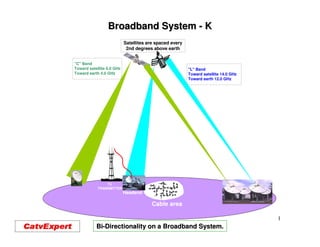
  • 1. Broadband System - K Satellites are spaced every 2nd degrees above earth "C" Band Toward satellite 6.0 GHz "L" Band Toward earth 4.0 GHz Toward satellite 14.0 GHz Toward earth 12.0 GHz TV TRANSMITTER Headend Cable area 1 Bi-Directionality on a Broadband System.
  • 3. Bi-Directionality on a Broadband System. Since a HFC system is a bi-directional operating system, the frequency allocations are: •From Headend to the Subscribers : 50 to 750, 870, or 1,000 MHz •From the Subscribers to the Headend : 5 to 40, 42 or 65 MHz •We now are starting to see: 5 to 65 MHz for return freq. •And forward frequency from: 85 to 870 or 1,000 MHz 3
  • 4. Bi-Directionality on a Broadband System. A Broadband HFC Communication system utilized two types of communications technology: • Fiber optic technology is used to transport signal for the long distance. Usually one fiber transmits forward signal (50-870 MHz from the Headend to a Optical Node and one more fiber transmits return signal (5 - 40 MHz) from a Node to the Headend. • Coaxial cable is used from the NODE and it is transmitting in both directions (50-870 / 5-40 MHz), from the Optical Node to the each subscribers. • The OPTICAL NODE, transfers Light Signal, coming from the Headend, to Electrical Signal (RF and Digital), sending these signals to each subscribers by coaxial cable. • The OPTICAL NODE, also Transfers Electrical Signal (RF and Digital) from all the customers to light signal, sending them to the Headend. 4
  • 5. Bi-Directionality on a Broadband System. All optical NODE must be equipped with a Photo diode on the forward path, a bi-directional filter at each output of the coaxial system to permit an HFC system to operate in a bi-directional way and a return Laser to transmit return signal toward the headend. Photo diode RF Amp. Fibre 50 - 1,000 MHz Bi-Directionnel 5-40 / 50-1,000 MHz 50- Filtrer Fibre 5 - 40 MHz Coaxial Cable LASER 5
  • 6. Bi-Directionality on a Broadband System. All RF amplifier must be equipped with a bi-directional filter at each input and outputs to permit an HFC system to operate in a bi-directional way. Section RF Section RF 50 - 1,000 MHz 50 - 1,000 MHz Bi-Directionnal Bi-Directionnal 5-40 / 50-1,000 MHz 5-40 / 50-1,000 MHz Filter Filter Coaxial Cable Coaxial Câble Section RF Section RF 5 - 40 MHz 5 - 40 MHz 6
  • 7. Optical NODE. Light 50-870 MHz 50- 50-870 MHz 50- Coaxial Cable Light 5-40 MHz 5- 5-40 MHz Fiber Optic RF section Optical receiver Optical Transmitter 50-870 MHz 50- 5-40 MHz 7
  • 8. Determining the Required Operating Level of the Return System. •Because the return path on a Broadband system works on a concept of UNITY GAIN, the system need to determine the required Return Input Level at each active equipment (Amplifier and Node). •That return Input level need to be at the output of the housing. •That Return Input LEVEL is usually between : 15 to 20 dBmV 5-40 50-870 5-40 MHz MHz 5-40 MHz MHz RF Amp. 27 Signal from customer 5 MHz 40 15 or 20 dBmV DOCSIS Signal Return Input 8
  • 9. Operating Level of the Return System. Once the operating level is determine, it is also very important to use the output test point to introduce the signal from the RETURN TRANSMITTING EQUIPMENT used for this operation. The actual level at the input of the return amplifier will change depending on the type of amplifier utilised. These amplifiers can be Line Extender, Mini-Bridger and Distribution amplifiers Return TX Equipment Test Test Point Point 50-870 MHz H H 27 L L Signal from customer 5 MHz 40 Test 15 or 20 dBmV Test Status Point Monitoring Point DOCSIS Signal 5-40 MHz EQ RF Amp. JXP Attenuator Return input level 9
  • 10. Operating Level of the Return System. After the HFC system has been aligned in both direction, each Cablemodem output must be adjusted, to hit a + 15.0 or + 20.0 dBmV at each input housing of all the NODE or RF Amplifiers on the HFC system. This is done automatically by DOCSIS operating system. 10
  • 11. Unity Gain. •Unity Gain, basically means output @ 1 and output @ 2 will have a different gain and slope, to fit in the required Input @ 3 •Each amplifier need to be adjusted locally, to hit the proper level at the node or the amplifier at location @ 3 *= Where return amplifier are adjusted 11
  • 12. The Fiber Optic Section. The fiber optic section, on a HFC system, is a flat operating system, in both, the forward and the reverse section. 12
  • 13. The Coaxial Cable Section. The loss of signal, in the coaxial section, works differently then fiber optic section, as frequency increase, signal loss also increase. The slope response must be constant, The forward and return response slope on on this side of all the amplifier, for the this side of the amplifier, depends on the forward section (50/870 MHz) as for the length of cable and the loss of the passive return section (5/40-42 MHz) (5/40- equipment, placed between the previous amplifier 13
  • 14. Adjusting the Return Signal on a Broadband System. Adjusting the forward section, is something, technician have been doing for year. Adjusting the reverse system is quite different, it either requires: • Two technicians communicating, to properly adjust the return amplifier. • 2 or 4 Modulators to be transported at each amplifier, a Spectrum Analyzer at the Headend, connected to a Modulator, and a TV set at each amplifier. • Or the use specialized equipment, We need to adjust the Gain and Slope of the return amplifier at 1 to have the proper input signal level at: 2 14
  • 15. Adjusting the Return Signal on a Broadband System. Return signal provided by return sweep equipment After you have decided the right RETURN input level (15 dBmV in most cases), you need to add the test point loss and begin adjusting the return system. 15
  • 16. Adjusting the Return Signal on a Broadband System. •When we adjust the return section of a HFC system, you must remember that you need to install a RETUN EQ and RETURN PAD, so you can hit the right return level at the following amplifier or node. •These EQ and PAD goes on the left of the return amplifier, toward the next amplifier or optical node. •The EQ is for setting the proper slope, which should be flat at the next ampifier •The PAD, is for setting right input level at the next amplifier. Return EQ Return 1 PAD Return 2 In some instance this could be a thermal PAD Could be 1, 2 3 or 4 return input 16
  • 17. Adjusting the Return Signal on a Broadband System. 8 Return signals +35 dBmV Between 5 & 42 MHz with a -20 dB test point Optical NODE The amplitude of 8 signals are transmitted in FSK with also the INGRESS level between 50-52 MHz or 72-75 MHz 50- 72- 0 dBm CMTS Carrier Level Headend from Headend 9581-SST 9581- Signal Optical Equipments INGRESS from Headend Optical Interconnection 17
  • 18. Adjusting the Return Signal on a Broadband System. Return RF level at headend INGRESS level at headend Above is the picture of the eight (8) signals been sent from the input of the return signal. The bottom section one show the ingress on the return signal been tested. Both of these information are read in the forward path of the HFC system. 18
  • 19. The Return Signal on a Line Extender. Signal loss between the return input and the input at the Return IC : 1.5 dB for H/L coupler. 1.5 dB thru 20 dB test point 1.5 dB for return input Status monitoring Total : 4.5 dB 19
  • 20. The Return Signal on a Mini-Bridger. Signal loss between the return input and the input at the Return IC : 1.5 dB for H/L coupler. 1.5 dB thru 20 dB test point 4.5 dB for splitter 1.5 dB for return input Status monitoring Total : 9.0 dB 20
  • 21. The Return Signal on a High Gain Amplifier. Signal loss between the return input and the input at the Return IC : 1.5 dB for H/L coupler. 1.5 dB thru 20 dB test point 4.5 dB for splitter 4.5 dB for 2nd splitter 1.5 dB for return input Status monitoring 21 Total : 14.5 dB
  • 22. Difference in Response Between a 20 and 30 dB Test Point. 22
  • 23. Amplifier Equipped with 30 dB High Impedance Test Point. With amplifiers equipped with high impedance, 30 dB test point, I strongly recommend installing a 20 dB multitap, at each output of the amplifiers, that way you will get a truer reading when adjusting the forward and the return path. 23
  • 24. Signal Loss Between 2 Different Return Path. Example of gain required for return signal Cable TX-625 Loss at : 860 MHz 1.94 dB/100' Loss at : 5 MHz 0.13 dB/100' Loss at : 40 MHz 0.38 dB/100' Input amplifier, Input amplifier, Ch : 5 15.00 dBmV Distance amplifier 1 - 2 Ch : 5 15.00 dBmV Ch : 40 15.00 dBmV 1550 ft Ch : 40 15.00 dBmV 31.07 dB / 860 MHz 1 2 Headend -1 dB 5.89 dB / 40 MHz H H H H L L L L Ch : 5 40.00 dBmV -12 dB Ch : 40 40.00 dBmV H Distance amplifier 1 - 3 H L L 800 ft 27.52 dB / 860 MHz Gain at: 5 MHz 29.50 dB 3.04 dB / 40 MHz Gain at: 5 MHz 18.02 dB Gain at: 40 MHz 29.50 dB Gain at: 40 MHz 21.89 dB 3 In général Return Opt. Tx H H Input amplifier, L L requires around + 35 dBmV Ch : 5 15.00 dBmV input for proper operation. H Ch : 40 15.00 dBmV Required output L Level for the next amp. Gain at: 5 MHz 28.04 dB Gain at: 40 MHz 30.04 dB Required output Level for the next amp. 24
  • 25. Sequence for Adjusting the Return Path. For the return path, the system should be adjusted in the following sequence. Return Set-in up sequence; 1. From Node to Headend 2. From Amp. 1 to Node 3. From Amp. 2 to Amp. 1 4. From Amp. 3 to Amp. 2 5. From Amp.4 to Amp. 3 25
  • 26. Multi wavelength return frequencies. Return Return Optic Optic RX TX 8 8 7 7 Single fiber optic with 8 “CWDM” frequencies 6 6 5 5 4 4 3 3 2 2 With CWDM technology, it is now 1 1 possible to have 8 return laser transmitting on one fiber. CWDM CWDM 26
  • 27. Multi wavelength return frequencies. 8 7 6 5 Opt. Return RX 8 4 7 6 5 Each optical coupler will require a 3 different value, so all light levels will 4 be within a 2 dB in level 3 Each return laser will also required the right wavelength frequency. 2 2 1 1 27
  • 28. Multi wavelength return frequencies. -6.44 -6.86 -6.95 dBm CWDM The loss of each return TX will be: 8.0 dB 2.64 dB 3 1= 3.0 -(3.63 - 3.2 - 1.43- 1.8 - 8.0) = -6.95 dBm 6.8 dB 1.8 dB 3 dBm 4.0 km 2= 3.0 -(4.1 - 4.0 - 1.8 - 8.0 ) = 6.86 dBm 1.43 dB loss 4.1 dB 2 3.2 dB 3 dBm 3= 3.0 -(6.8 - 8.0 ) = 6.95 When using CWDM technology, we should 11 km try to keep all of the light level within 1.5 dB 3.63 dB loss from each other. The thru loss of the CWDM is not calculated 1 3 dBm 28
  • 29. Signal Loss Between Two Cable Modem. Loss of signal between Cablemodem and Input of the return amplifier. As we go further away from the amplifier, the signal loss between the Cablemodem and the amplifier get smaller, this will shown in the next presentation. 29
  • 30. Actual Level Required at Each Cable Modem for Proper Operation. Actual level in dBmV, required out of the Cablemodem, to hit proper input at the next amplifier or Optical Node, where the forward signal output is : 14 dBmV at 750 MHz Cable P-III-625 INPUT @ 870 MHz OUTPUT 34 - 46 Forward output + 14.0 dBmV @ 870 MHz 17.95 dVmV dBmV 100' 100' 100' 100' 100' 100' 100' 29 29 26 23 20 15.5 10 15 dBmV - 1.37 - 1.37 - 1.37 dB dB dB QAM TV TV TV Cablemodem - 7.0 Cablemodem Cablemodem - 7.0 - 7.0 5 MHz 40 dB dB Output dB Output Output 52.37 dBmV 48.44 dBmV 43.02 dBmV Signal required out of each Cablemodem, to hit the proper required 15 dBmV at the input at the housing This actually shows why new Cablemodem are now equipped with a output level control. This output level is controlled by the CMTS or the SERVER located in the headend. 30
  • 31. A Bi-Directional Operating System. Fiber optic HE RING Reverse Path from caller From server to call Response from call From server to caller IP Telephone call or Cable modem Start from here. Hi….. 31
  • 32. A Bi-Directional Operating System. •You’ll now see a short PC Video demonstration a HFC return signal. Pattern of the Video Recording of the return signal: •19:30:25 5 to 50 MHz upstream system. •19:30:25 3 active cable modem carriers (3.2 MHz DOCSIS) •19:31:10 Ingress appear between 5 to 18.5 MHz. •19:31:18 Ingress grows substantially stronger. •19:31:30 Ingress disappear. •19:31:33 Common path distortion (CPD) appears. •19:31:41 Common path distortion grows very severely. •19:31:51 Common path distortion goes away. •19:32:15 All traffic is now OK. •19:32:34 Analyzer a ZERO SPAN, centre frequency at 41 MHz •19:32:52 Noise floor rises to about 15 dB C/N. •19:32:52 Interference disappears, Noise floor back to 30 dB C/N •19:33:57 Analyzer is brought back to frequency domain mode. mode. •19:34:27 End of recording. 32
  • 33. A Bi-Directional Operating System. Controlling INGRESS is possible by utilising a device called ClearPath. A ClearPath is a return switch that locate the source of INGRESS in a HFC system. To determine where the ingress is located, the ClearPath selectively switches a 6 dB pad into the return path. In locations where the ingress is severe, the ClearPath can also switch off the entire upstream band until the ingress sources in repaired. Technical specifications: •90 volts, 15 amp power passing •Smooth, non-disturbing switching •Switching time 10 ms •Surge protected •Provides temporary release for severe ingress •Single agile FSK carrier 33
  • 34. A Bi-Directional Operating System. Controlling INGRESS A 1. With INGRESS coming from section A and the return path without ingress control, the return system might not been operational. If ClearPath-4 is installed, and with a ( 6 or 40 dB attenuation Pad ) operating, the rest of the return path becomes fully operational. 2. The ClearPath can be controlled by using a simple software and a spectrum analyzer or a complete software, that will activate the proper ClearPath, activate the attenuation Pad and give the proper location. 34
  • 35. A Bi-Directional Operating System. Controlling INGRESS •TraffiControl is a powerful new feature for Trilithic Reverse Path Maintenance System. Path This system can not only detect INGRESS hiding inside your return services, it can return scan your return system and detect excessive ingress, logs the event, generates event, alarms and takes other programmed actions, like finding where the problem occur by the opening and closing and selecting the proper ClearPath. •TraffiControl can also select the operating section of the return path and forget about return the none occupied section, as shown above. 35
  • 36. A Bi-Directional Operating System. Controlling INGRESS Ingress Switch With newer optical NODE and RF amplifier, it is now possible to install INGRESS Switch inside the amplifier and controls INGRESS. This INGRESS switch is capable of inserting a 6 dB PAD or a 40 dB PAD at distance. The 6 dB PAD help us locate the problem area and the 40 dB PAD remove from the return system the problem area.. 36
  • 37. A Bi-Directional Operating System. Controlling INGRESS •One other way to controlled and look for INGRESS, is by using a 9581-SST and 9581- 9581-SSR. You then go to any amplifier, get the return signal from the 20 dB test 9581- the point and look at the ingress at the 9581-SST at the Headend. By removing 9581- attenuator PAD before the return IC you can actually tell where the INGRESS is coming form. •The problems with this solution, every time you remove a PAD from the return from system, you actually stop the return system to operate and you will also have to will move from amplifier to amplifier, before you can locate the problem area. problem 37
  • 38. A Bi-Directional Operating System. Controlling INGRESS Pressing here will introduces a 6 This return REVERSE TEST PROBE can also help locating dB PAD INGRESS. By pressing a control, a 6 dB pas will be introduce to the return system and let you know if you have located the ingress or if the ingress is coming from somewhere else. 38
  • 39. A Bi-Directional Operating System. It is also possible to read return INGRESS and CPD on the return system with the use of a spectrum analyzer. Return system with INGRESS. Return system without INGRESS. 39
  • 40. A Bi-Directional Operating System. Adjusting a return system in the field. 40
  • 41. A Bi-Directional Operating System. Controlling INGRESS One other good way to removed INGRESS on a bi-directional system, is to install a High Pass Filter at each location where bi-directional signal are not required. 41
  • 42. A Bi-Directional Operating System. Controlling INGRESS With some systems operating a VIDEO on DEMAND or a PAY TV System, you should installed a INGRESS control unit with the capacity of talking to the controls units installed at each customer with these services. These controls units are usually requiring a frequency between 9 to 10 MHz 42
  • 43. A Bi-Directional Operating System. Testing return signal, from the home to the headend. Some equipment can test the quality of the return signal. These equipments send signal to a headend equipment, this equipment does some calculation and send you the result on the forward path. The picture show 8 frequencies from 5 to 42 MHz been sent from the home to the headend. The headend piece does some C/N calculation and let you if the system meet the return requirement. This system send the following frequencies at the headend: 5.5, 13, 18, 24, 27, 30, 34, and 39.6 MHz. The level received at the headend is around 25 dBmV. The highest INGRESS level been around –25 dBmV, where the C/N of each of those frequencies are between; 42 to 36 dB C/N. 43
  • 44. A Bi-Directional Operating System. Controlling INGRESS A High Pass Filter installed at each home, not requiring by-directional communication , will help the system control his ingress problem. 44
  • 45. Test! 45
  • 46. •What is a proper return level at the input of an RF amplifier? _____________________________________________________________ •In what direction do we line-up the return system on a HFC system? line- ______________________________________________________________ •What happen to return RF signal at the NODE? ______________________________________________________________ •How many return signal do we generally combined at the headend? _______________________________________________________________ •Are all the cable modem adjusted at the same level at the customer? customer? _______________________________________________________________ •What type of modulation is generally used for cable modem? _______________________________________________________________ •Where is the return equalizer situated on the RF section of an amplifier? amplifier? _______________________________________________________________ •What is called the none wanted signal, that can actually stop the return system to work? the _______________________________________________________________ 46
  • 47. 47