SlideShare ist ein Scribd-Unternehmen logo
1 von 248
Downloaden Sie, um offline zu lesen
BR 67
                                                            RIGGING AND DECK GEAR


                                      CHAPTER 3

                              RIGGING AND DECK GEAR

                                      CONTENTS

Paragraph
03001.      Introduction to Types of Rope
03002.      Construction, Characteristics and Details of Supply of Natural Fibre Cordage
03003.      Construction, Characteristics and Details of Supply of Man-made Fibre Cordage
03004.      Twines, Lines and Spunyarn
03005.      Junk and Rounding
03006.      Construction, Characteristics and Details of Supply of Steel Wire Rope (SWR)
03007.      Handling of Natural and Man-made Fibre Cordage
03008.      Preparing Natural Fibre and Man-made Fibre Ropes for Use
03009.      Handling of Wire Rope
03010.      General Remarks on Steel Wire Rope
03011.      End Terminals on Wire Rope
03012.      Factors of Safety, Safe Working Loads and Proof Loads
03013.      Orders and Terms Used in Handling Hawsers, Ropes and Cables
03014.      Handling Hawsers
03015.      Bends and Hitches
03016.      Knots
03017.      Whippings
03018.      Mousing
03019.      Seizings
03020.      Worming, Parcelling and Serving
03021.      Lashing
03022.      Splicing Hawser-laid and Multi-plait Cordage
03023.      Splicing Braided Cordage
03024.      Splicing Steel Wire Rope
03025.      Splicing Cordage into Wire
03026.      Mechanical Splicing
03027.      Making a Temporary Eye Using Bulldog Grips
03028.      Nets - Provision and Cargo
03029.      Nets - Brow Safety
03030.      Rigging Shackles
03031.      Roller Blocks
03032.      Swivel Ring Shackles
03033.      Thimbles
03034.      Thimble and Link Assembly for Towing Hawsers
03035.      Common Rings
03036.      Hooks
03037.      Rigging Screws (Also Known as Turn-buckles or Bottlescrews)
03038.      Guardrail Turnbuckle Assemblies
03039.      Eyeplates and Eyebolts
03040.      Union Plates
03041.      Swivels
03042.      Rigging Slips
03043.      Blocks
03044.      Marking and Identifying Portable Rigging Fittings
03045.      Purchases and Tackles - Introduction


                                                                                      3-1
                       ADMIRALTY MANUAL OF SEAMANSHIP
BR 67
RIGGING AND DECK GEAR
                                CONTENTS (Continued)

Paragraph
03046.      Examples of Tackles and Purchases
03047.      Hand Operated Chain Blocks
03048.      Tirfor Pulling and Lifting Machines
03049.      Air-powered Hoist
03050.      Slinging
03051.      Proprietary Lifting Slings
03052.      Special Slinging Precautions
03053.      Slinging and Responsibilities in HM Ships
03054.      Ammunition Secondary Re-supply Equipment
03055.      Estimation of Stresses in Derricks and Cranes
03056.      Derricks
03057.      Cranes
03058.      Winches
03059.      Introduction to Improvised Rigs of Derricks, Sheers, Gyns and Ropeways
03060.      Gear Required and Principles Involved When Rigging Improvised Lifting Gear
03061.      Rigging Derricks, Sheers, Gyns and Ropeways
03062.      Raising Derricks and Sheers
03063.      Plank Stage
03064.      Bosun’s Chair
03065.      Manpower Calculations
03066.      Boat Booms
03067.      Accommodation Ladder
03068.      Mediterranean Ladder
03069.      Pilot Ladder
03070.      Brows
03071.      Scrambling Nets
03072.      Sounding
03073.      Boats Lead and Line
03074.      Hand Lead and Line
03075.      Dress Ship
03076.      Awnings
03077.      Fendering
03078.      Berthing
03079.      Submarine Berthing and Slipping
03080.      Submarine Berthing - Slipping Vessels Alongside - Personnel
03081.      Submarine Docking / Undocking Procedures - Personnel
03082.      Emergency Casing Equipment Bag (EMCEB)
03083.      Ship Movement in Naval Bases
03084.      Designated Tug Lines.
03085.      Seamanship Stowages

                                       Annexes

Annex 3A:     SWL Blocks in Various Tackle Configurations
Annex 3B:     Polyester Roundslings – Production of a Log Book


3-2
                              THE NAUTICAL INSTITUTE
BR 67
                                                                  RIGGING AND DECK GEAR
                                         CHAPTER 3

                                          RIGGING

03001. Introduction to Types of Rope

       a.   Most ropes can be described as belonging to one of three main types:

            Cordage made of natural fibres (NFC)
            Cordage made of man-made fibres (MMFC)
            Steel wire rope (SWR)

       b. In the Royal Navy, ropes are described by reference to the diameter of the rope
       measured in millimetres (mm), the type of construction and the material from which it
       is made - for example, 36mm braidline polyester. However, certain proprietary brand
       ropes contain a mixture of materials, either from two of the three main types, or from
       a mix of materials from one type, e.g. a combination of man-made fibres. These ropes
       are usually referred to by their proprietary name.

03002. Construction, Characteristics and Details of Supply of Natural Fibre Cordage

       a. Use in the Royal Navy of natural fibre cordage has dwindled in recent years,
       primarily because man-made fibre cordage is stronger, harder wearing, more cost
       effective, and in most circumstances, more functional than natural fibre cordage.
       However, natural fibre cordage is still required for certain tasks, and this requirement
       is likely to continue for the foreseeable future. All Natural Fibre Cordage supplied to
       the Royal Navy is supplied with a test certificate, and certificate of conformity, on which
       are listed the date of manufacture, the British standard to which the rope has been
       manufactured, and the guaranteed minimum breaking strength of the rope.

       b.   Construction.

            (1) Natural fibre ropes are made from fibres of varying length dependent upon
            their source, and the first process is to comb out these fibres into a long, even
            ribbon shown in Fig 3-1.

                    Fig 3-1. Fibres of a Natural Fibre Cordage Rope


            (2) The ribbons are then twisted up into yarns, and the twist given binds the
            fibres firmly together so that they hold by friction when the yarn is subjected to
            strain. This process is known as ‛spinning’, and the yarns are said to be spun left-
            handed or right-handed according to the direction of the twist. Next, a certain
            number of yarns are twisted together to form strands. The number and size of
            yarn to make each strand depends on the size of the rope to be made. This stage
            is known as ‛twisting the strands’, and again, the twist can be left-handed or right-
            handed. Three or four strands are now made up into a left-handed or right-handed
            rope. This process is called ‛laying’ or ‛closing’, and is always carried out in the
            direction opposite to that used in the previous stage of twisting the strands; it is,
            moreover, distinct from the simple spin or twist and is two-fold, in that:


                                                                                              3-3
                        ADMIRALTY MANUAL OF SEAMANSHIP
BR 67
RIGGING AND DECK GEAR
                  (a) The strands are twisted up together to form the rope.

                  (b) At the same time the strands are rotated individually in the direction of
                  the original twist.

                       i.   Were this not done, laying the strands up together would tend to
                       untwist the yarns in each strand.

                       ii.  As the rope is laid up, its length contracts like a coiled spring,
                       giving it certain elasticity. The harder the twist given to the strands in
                       laying, the shorter will be the resultant rope and thus a rope is said to be
                       hard-laid, ordinary laid or soft-laid rope. In practice, three strands of
                       275 metres lay up into a rope of about 220 metres in length. Three
                       strands so laid up constitute a hawser-laid rope (Fig 3-2). Right-handed
                       hawser-laid rope is the only type of natural fibre cordage now used in
                       the Royal Navy.

      Fig 3-2. Component Parts of a Natural Fibre Right-handed Hawser-laid Rope


        c. General Characteristics. The strands tend to unlay unless the end of the rope is
        whipped (ie firmly bound) with twine. The rope will stretch under load and will not
        completely recover when the load is removed. The rope acquires a permanent and
        irreversible set; the higher the load in relation to the breaking strength, the greater the
        set. The set may be observed by the extension in length and reduction in diameter
        when the rope is slack and will eventually render the rope unfit for service. The older
        and more worn the rope, the less elasticity it will possess and the weaker it will
        become. Rope under load will tend to twist in the opposite direction to that of its lay
        and thereby tend to unlay itself, but it should regain its normal form when slack. When
        wet, Natural Fibre Cordage will usually shrink in length in proportion to the amount by
        which it swells in diameter, but it will recover its original length when dry and after use.
        Rope which is continually subjected to heat and damp - when in the tropics, for
        example - will lose its elasticity and strength sooner than rope used under normal
        conditions of temperature and humidity.


3-4
                                  THE NAUTICAL INSTITUTE
BR 67
                                                          RIGGING AND DECK GEAR
d. Materials Used. There are now only two natural fibre ropes supplied to the Royal
Navy, Manila and Sisal. The fibres of the rope are treated with a water proofing
solution during the first stage of rope making when the fibres are combed into ribbons.

    (1) Manila Rope. This rope is made from the leaf fibre of the Abaca plant, which
    is grown in the Philippines and shipped from the port of Manila (whence its name),
    and also Sumatra and Borneo. When new and untreated, it is a deep golden-
    brown in colour. The rope is flexible, durable, strong when compared with other
    natural fibre ropes, impervious to salt water and stands up well to wear and tear.
    However, its advantages over man fibre cordage are that it stretches less, will
    surge more readily around a winch or capstan, and does not fuse when heated (ie
    when being surged under strain or used as a check stopper). It is currently used
    as a check stopper for towing operations. Manila rope is marked with one black
    yarn in each of two strands, and supplied in coils of 220 metres.

    (2) Sisal Rope. This rope is made from the Agave Sisalana plant, which is a
    member of the cactus plant. It is grown in Brazil, Malagasay, Kenya, Tanzania,
    Haiti and Java; when new and untreated it is hairy, and of a pale straw colour. New
    sisal is as strong as manila, but is not as flexible, durable or resistant to wear and
    weather. Its principle use is as a slip rope during replenishment at sea, and its
    advantages over man-made fibre ropes are similar to those outlined for manila.
    Sisal rope is marked with one red yarn in one strand, and supplied in coils of 220
    metres.

e. Strength. A method of finding the approximate breaking strength of manila and
sisal cordage is to divide the square of the diameter of the cordage in millimetres by
200, the answer being in tonnes. This allows for a good margin of safety. To estimate
the strength of a rope which is well worn but in good condition, apply the formula as
for new rope, but use the actual and not the nominal diameter. However, the only
really reliable method by which the strength of a rope may be determined is to test a
sample of the worst part of the rope to destruction.


                                                                                      3-5
                 ADMIRALTY MANUAL OF SEAMANSHIP
BR 67
RIGGING AND DECK GEAR
      f. Details of Natural Fibre Cordage Supplied to the Royal Navy. Table 3-1 gives
      details of natural fibre cordage supplied to the Royal Navy.

      Table 3-1. Details of Natural Fibre Cordage Supplied to the Royal Navy

                               Naval Stores         Minimum              Supply
         Type        Size
                                   No             breaking load       denomination
      Manila       8mm       0350/571-3074          0.45 tonnes            220m
                   12mm      0350/125-0228          1.06 tonnes            220m
                   16mm      0350/942-5025          2.03 tonnes            220m
                   20mm      0350/571-3077          3.25 tonnes            220m
                   24mm      0350/942-5026          4.57 tonnes            220m

      Sisal        12mm      0350/942-5042          0.95 tonnes            220m
                   16mm      0350/942-5044          1.80 tonnes            220m
                   20mm      0350/942-5046          2.85 tonnes            220m
                   24mm      0350/942-5048          4.07 tonnes            220m
                   28mm      0350/942-5050          5.33 tonnes            220m
                   72mm      0350/942-5060          32.7 tonnes            220m

      g. Care and Maintenance of Natural Fibre Rope. Natural fibre rope does not have
      a permanent elastic limit. The life of a rope depends on the amount it is used under
      strain, because the fibres tend to slip a small amount under each load in spite of the
      twist given during manufacture. NFC should not be stowed away while it is wet; if this
      is unavoidable the rope must be brought out and dried at the first opportunity. Although
      any rope in good condition can be confidently expected to bear its full working load
      with ease, allowance for wear must be made in assessing the full strength of used
      rope, particularly when it has been subjected to hard conditions. Before estimating the
      strength of such a rope it should be examined for damage, chafe, rot and fatigue.
      Serious damage can be seen when the strands are distorted and bear unequal strain,
      or when the rope becomes opened. Rot can be detected by the smell of the rope and
      by opening out the strands and examining their inner surfaces. Should they be healthy
      and strong, all is well; if they are powdery, discoloured, weak or can be plucked out,
      rot exists and the rope should be condemned. Rope may also be subject to chemical
      attack. Many rust-removal compounds are based on phosphoric acid which has a
      disastrous effect on natural fibre, and for this reason cordage should always be
      protected from contamination. If doubt exists as to the serviceability of a rope, the rope
      should be condemned.


3-6
                               THE NAUTICAL INSTITUTE
BR 67
                                                                  RIGGING AND DECK GEAR
03003. Construction, Characteristics and Details of Supply of Man-made Fibre Cordage

       a. Prior to 1939, natural fibres were the only materials available for cordage
       manufacture. In 1939 a new man-made yarn known as Nylon, invented earlier,
       became available to the cordage industry. From the outset it was evident that this
       synthetic fibre possessed such remarkable qualities that a great advance had been
       made in the cordage industry. The technical name for Nylon is Polyamide. Both
       names are interchangeable but the latter is preferred in the Royal Navy to distinguish
       it from other synthetic materials, which were subsequently developed and are used for
       cordage manufacture. These latter materials are Polyester, Polypropylene,
       Polyethylene, and the three most recently developed, Aramid, a derivative of
       polyamide, polyolefin, a derivative of polypropylene, and High Modulus
       Polyethylene (HMPE). The various man-made fibre ropes have different
       characteristics which make them especially suitable for specific tasks. For example,
       polyamide has greater elasticity than polyester and is therefore very suitable for use
       as towing hawsers and boat anti-shock strops. Polyester, because of its relatively low
       elasticity and excellent weather and abrasion resistance, is suitable for berthing ropes
       and replenishment lines, and staple spun polypropylene is appropriate when light,
       floating, easily handled ropes such as towing hawser messengers and swimmer
       recovery lines are required. Polyethylene in its basic form is used principally in ships’
       diving operations as a swim-line, because it is orange in colour and therefore easily
       visible. It has similar characteristics to, but is weaker than, polypropylene. Aramid is at
       present used only for dressing lines, where, because it is strong, non-inductive and
       has little elasticity, it is replacing steel wire rope. High Modulus Polyethylene (HMPE),
       a very high strength, low stretch fibre, is being introduced as a replacement for steel
       wire rope berthing springs. Polyolefin, introduced as a first generation plaited berthing
       hawser, is being replaced by rope blending polyester and polypropylene. Cordage
       made from man-made fibre is naturally rot-proof and almost impervious to water.
       Unless specially treated, this type of rope, except Aramid and HMPE, will stretch far
       more than natural fibre cordage. This stretch ranges from 25-30% for film-fibre
       polypropylene to 45-50% for polyamide at breaking load. All man-made fibre ropes
       can be considered non-flammable in that they do not readily ignite or burn with a
       flame. In the molten state these materials will burn but only at a temperature
       approximately twice that of their melting point.

       b. Construction. Polyamide, polyester, polypropylene and polyethylene all fall into
       the polymer group. Polyamide is produced from coal whereas the remainder are
       produced from oil. Most man-made fibres are made from either continuous filaments,
       or yarns of staple fibres, but polypropylene ropes can be manufactured from
       multifilament, monofilament, staple or film-fibre. Details are as follows:

           (1) Staple. These fibres vary in length and the processing machine on which
           they are to be used determines this length. For rope-making the staple length
           varies between 150mm and 1300mm. Although weaker than continuous filament
           cordage of equivalent size and material, staple spun cordage is ideal in
           applications where a good grip is required.

           (2) Multifilament. These yarns are composed of a number of very fine filaments
           of circular cross-section twisted together, each filament being continuous
           throughout the yarn length.


                                                                                              3-7
                        ADMIRALTY MANUAL OF SEAMANSHIP
BR 67
RIGGING AND DECK GEAR
        (3) Monofilament. These are usually circular in cross-section and are
        continuous throughout their length. Micrometer-type gauges are used to measure
        their diameter, which, for rope making, can range from 0.125mm upwards.

        (4) Film-fibre. Film-fibre is composed of fibrils produced by longitudinal splitting
        when an extruded tape or ribbon is twisted into a yarn.

        (5) 3 Strand Hawser-laid. Hawser-laid man-made fibre ropes are manufactured
        in the same manner as natural fibre ropes, with three strands laid up and a right-
        hand twist (Fig 3-2). Each strand is composed of a sufficient number of uniform
        filaments of specified polymer to give a rope the required strength. A higher twist
        is imparted to the strands than to those of natural fibre, and the ropes are
        subjected to a form of heat treatment to stabilise the lay and thereby reduce the
        tendency of the strands to separate in service. It is important that the twist and
        balance of the lay should be undisturbed, especially when being spliced.

        (6) Plaited Rope. The rope is constructed of eight strands arranged in four pairs
        (Fig 3-3), two pairs of left-hand lay and two pairs of right-hand lay. This
        arrangement is known commercially as ‛Squareline’ but in naval use is commonly
        referred to as multi-plait. Its properties are very similar to hawser-laid except that
        it is a softer rope and does not kink.

                      Fig 3-3. Construction of Plaited Rope


        (7) Braided Rope. This rope, known commercially as core/cover rope, is
        constructed by crossing and re-crossing the yarns or strands in ‛maypole’ fashion
        such that each yarn or strand passes alternatively over and under one or more of
        the others to form a circular tubular sheath, which may contain a core. The use of
        braided cordage in the Royal Navy is limited to certain specific applications.
        Braided construction gives the following advantages over hawser laid ropes; good
        flexibility and easy handling when wet or dry, new or worn; non-rotating and will
        not kink; more grip on capstans or warping drums because of the greater contact
        area. At present the only categories of braidline in use in the Fleet are a braided
        sheath around a core of either parallel strands, or a three-strand rope, or a
        multiplicity of three strand rope core members. All braided ropes fall into one of
        the following categories:

             (a) A braided sheath around a braided core having a heart of parallel
             strands (Fig 3-4).

             (b) A braided sheath around a hollow braided core (Fig 3-5).


3-8
                            THE NAUTICAL INSTITUTE
BR 67
                                                           RIGGING AND DECK GEAR
             (c) A braided sheath around a core of either parallel strands, or a three-
             strand rope, or a multiplicity of three strand rope core members. (Fig 3-6).

             (d) A braided sheath with no core (hollow-centred rope).

        (8) Guardwire. This type of rope is constructed of a load bearing core of densely
        packed parallel filaments, generally polyester, and encased within a tough durable
        polyethylene sheath. An example of this type of rope is parafil.

        (9) Aramid. This type of rope has a braided polyester sheath around a three-
        stranded Aramid multifilament core. 95% of the strength of this rope comes from
        the Aramid core.

        Note. Unlike other MMF cordage the Aramid core cannot be heat-sealed

   Fig 3-4. A Braided Rope with Braided Core and Heart of Parallel Strands


              Fig 3-5. A Braided Rope with Hollow Braided Core


Fig 3-6. A Braided Rope with a Multiplicity of Three Strand Rope Core Members


                                                                                      3-9
                    ADMIRALTY MANUAL OF SEAMANSHIP
BR 67
RIGGING AND DECK GEAR
       c.   Characteristics.

            (1) Polyamide. This multifilament cordage is approximately two-and-a-half
            times as strong as manila of equivalent size. It stretches by almost half its length
            before parting and gives little, if any, warning that it is about to reach the limit of
            its stretch. Used within its safe working load it will stretch approximately 25% of
            its length and has excellent recovery. It does not float and it loses approximately
            10% of its strength when wet. The melting point is 240-260°C and it is virtually
            unaffected by 80°C of frost. The working temperature range is -40ºC to +100ºC.
            Polyamide has a good weather and abrasion resistance and a high resistance to
            alkalis but low resistance to certain acids. Strong sulphuric acid, for example, will
            dissolve the fibres. The energy absorption qualities are excellent and are retained
            to a significant degree during repeat loading.

            (2) Polyester. This multifilament cordage is nearly twice as strong as manila of
            equivalent size. It stretches approximately 36% before parting. Used within its
            safe working load it will stretch 14% of its length and has excellent recovery. The
            strength is virtually unchanged when wet, it does not float, the melting point is
            240-260°C and it is virtually unaffected by 80°C of frost. The working temperature
            range is -40º to +100ºC. Polyester has excellent weather and abrasion resistance
            and high resistance to acids but not alkalis.

            (3) Polypropylene. This cordage is nearly twice as strong as manila of
            equivalent size and is the lightest in weight of the man-made fibres. It stretches
            up to 44% before parting. Used within its safe working load it will stretch 17% of
            its length. It retains its strength when wet and has a low water absorption. It will
            float indefinitely in water. The melting point is 160-170°C. The working
            temperature range is -40º to +80ºC. Polypropylene has high resistance to acids
            and alkalis. Multifilament and monofilament polypropylene is not normally used
            for load-bearing ropes.

            (4) Polyethylene. This cordage is about one-and-a-half times as strong as
            manila of equivalent size. It stretches 33% before parting, but used within its safe
            working load will stretch 14%. It floats, retains its strength when wet and has low
            water absorption. The melting point is 120-135°C. Because of its low softening
            temperature it is not recommended for load bearing application. High Modulus
            Polyethylene, a recently developed derivative of polyethylene, is size for size as
            strong as conventional steel wire rope.

            (5) Parallel Polyester Covered with Polyethylene Sheath (Guardwire). These
            ropes are light, thin and strong, require little maintenance and are resistant to
            creep and stretch. Tensile properties of parafil are close to those of steel wire
            rope, with the added advantage of electrical insulation and ultra-violet resistance.
            The dimensional and tensile properties are determined directly by the core yarn.
            As the polyethylene sheath is not a load-bearing component it follows that,
            provided the core yarn is undamaged, any damage to the sheath will not result in
            a loss of rope strength. These ropes are not affected by water, will not corrode or
            rot, and have an energy absorption two-and-a-half to three-and-a-half times that
            of steel wire rope of equivalent breaking load. These ropes are not suitable for
            winching or running through blocks because of the likelihood of sheath stripping,
            thereby exposing the core yarn to damage from abrasion. The smooth sheathing
            has excellent ice-shedding properties under severe conditions.


3-10
                                 THE NAUTICAL INSTITUTE
BR 67
                                                            RIGGING AND DECK GEAR
        Note. Because of the requirement accurately to test new guardwires
        manufactured from parallel polyester covered with a polyethylene sheath, they
        can only be produced by shore side authorities. Damaged or broken guardwires
        onboard ship must be temporarily replaced with a spliced 12mm Polyester rope
        Patt No 0350/923-7143. Whenever possible the polyester rope should form the
        lower guardrail, if necessary by swapping guardrails.

        (6) Aramid. These ropes are nearly six times as strong as manila of equivalent
        size. They require no maintenance and are highly resistant to stretch. However,
        Aramid has poor ultraviolet and abrasion resistance so the Aramid core is
        sheathed for protection in a braided polyester cover. Aramid ropes are very
        susceptible to damage if run through block sheaves or around winches that have
        a diameter less than thirty times that of the Aramid core of the rope.

   d. Identification. Like Natural Fibre Cordage, all Man-made Fibre cordage supplied
   to the Royal Navy comes with a test certificate, and certificate of conformity, on which
   are listed the date of manufacture, the British Standard to which the rope has been
   manufactured, and the guaranteed minimum breaking strength of the rope when new.
   To prevent confusion, particularly between polyamide and polyester ropes whose
   external appearance is identical, identification yarns, where possible, are incorporated
   in man-made fibre ropes, in accordance with British Standard BS 6033; Table 3-2
   gives the details. However, with certain smaller ropes it is not possible for the
   manufacturer to include an identification mark, and in the most recently developed
   type of ropes and in certain ropes that contain a mixture of fibre types, no common
   standard of identification exists; therefore the test certificate and certificate of
   conformity supplied with the rope should be regarded as the only reliable guide to the
   breaking strength of the rope.

            Table 3-2. Identification Yarns in Man-made Fibre Cordage

    Material          Identifying colour              Identification marking
Polyamide           Green                     One green yarn in one strand

Polyester           Blue                      One blue yarn in one strand

Polypropylene*      Brown                     One brown yarn in one strand or rope
                                              wholly coloured brown

Polyethylene        Orange                    One orange yarn in one strand or rope
                                              wholly coloured orange


                                                                                      3-11
                     ADMIRALTY MANUAL OF SEAMANSHIP
BR 67
RIGGING AND DECK GEAR
       e. Strength. The rule-of-thumb method of calculating the breaking strain of man-
       made fibre rope is to divide the square of the diameter by a known factor. Table 3-3
       gives the approximate strength of new cordage according to its diameter, d, in
       millimetres. However, it is emphasised that the test certificate supplied with the rope
       is the only accurate guide to the breaking strength.

Table 3-3. Calculation for Approximate Breaking Strength of Man-made Fibre Cordage

                                                 Formula for Calculating Breaking
                         Cordage
                                                             Strength
            High Modulus Polyethylene           d2/18 tonnes
            Aramid                              d2/40 tonnes
            Polyamide (under 32mm)              d2/50 tonnes
            Polyamide (32mm and over)           d2/60 tonnes
            Polyester (under 32mm)              d2/64 tonnes
            Polyester (32mm and over)           d2/66 tonnes
            Polypropylene                       d2/77 tonnes
            Polyethylene                        d2/106 tonnes
            Berthing rope (under 32mm)          d2/60 tonnes
            Berthing rope (32mm and over)       d2/64 tonne

       f.     Uses. The principle service uses of man-made fibre ropes are as follows:

              (1) Polyamide. Because of its elastic properties it is used for towing hawsers
              and anti-shock strops.

              (2) Polyester. Because of its low stretch, high strength, and excellent weather
              and abrasion resistance, these ropes are used as replenishment lines, safety
              nets, signal halyards and picking-up ropes.

              (3) Polypropylene. Being a floating rope it is used in its staple form for
              messengers associated with towing hawsers. It is also used for boat ropes,
              ammunition resupply whips, lifelines, and as the recovery line in Swimmer of the
              Watch rigs.

              (4) Polyolefin. Used to manufacture first generation of multi-plait berthing
              hawsers. See also sub para (8) below.

              (5) Polyethylene. This cordage, also a floating line and easily visible, is used
              principally in ships’ diving operations.

              (6)    Aramid. This cordage is at present used only for dressing lines.


3-12
                                   THE NAUTICAL INSTITUTE
BR 67
                                                         RIGGING AND DECK GEAR
      (7) Parallel Polyester Core with Polyethylene Sheath. This cordage is used for
      standing rigging, principally guardrails.

      (8)    A Polyester/Polypropylene mix now specified for berthing hawsers.

      (9) High Modulus Polyethylene. This cordage is a replacement for steel wire
      berthing springs. Its high cost is likely to limit its use in the Fleet.

  g. Details of Man-made Fibre Cordage Supplied to the Royal Navy. Table 3-4 to
  Table 3-11 gives details of most man-made fibre cordage available through Naval
  stores.

    Table 3-4. Polyamide Ropes and Lines Supplied to the Royal Navy

                                                         Minimum       Supply
                                      Naval Stores
            Type             Size                        breaking      Denom-
                                          No
                                                           load        ination
Polyamide 3 strand          24mm     0350/923-7129     12.0 tonnes    220m
Polyamide 3 strand          28mm     0350/923-7130     15.8 tonnes    220m
Polyamide 3 strand          32mm     0350/923-7131     20.0 tonnes    220m
Polyamide 3 strand          36mm     0350/923-7132     24.8 tonnes    220m
Polyamide 3 strand          40mm     0350/923-7133     30.0 tonnes    220m
Polyamide 3 strand          44mm     0350/923-7134     35.8 tonnes    220m
Polyamide 3 strand          64mm     0350/923-7137     72.0 tonnes    220m

Polyamide braided           21mm     0350/549-1143     8.70 tonnes    220m
Polyamide braided           64mm     0350/251-4431     90.0 tonnes    65m*

Polyamide multi-plait       48mm     0350/794-8239     42.0 tonnes    220m
Polyamide multi-plait       64mm     0350/543-0143     72.0 tonnes    220m
Polyamide multi-plait       80mm     0350/543-0149     110.0 tonnes   220m

Polyamide cord gunline      1.5mm    0350/571-3024     64 kg          860m

  * Braidline Bridle


                                                                                 3-13
                    ADMIRALTY MANUAL OF SEAMANSHIP
BR 67
RIGGING AND DECK GEAR
          Table 3-5. Polyester Ropes and Lines Supplied to the Royal Navy

                                                            Minimum      Supply
             Type             Size      Naval Stores No     Breaking     Denom-
                                                              Load       ination
 Polyester   3 strand        6mm       0350/923-7140      0.56 tonnes    220m
 Polyester   3 strand        8mm       0350/923-7142      1.02 tonnes    220m
 Polyester   3 strand       10mm       0350/879/5226      1.60 tonnes    220m
 Polyester   3 strand       12mm       0350/923-7143      2.27 tonnes    220m
 Polyester   3 strand       16mm       0350/923-7144      4.1 tonnes     220m
 Polyester   3 strand       20mm       0350/923-7145      6.3 tonnes     220m

 Polyester 8 plait blue      8mm       0350/529-7387      0.39 tonnes    220m
 Polyester 16 plait blue    10mm       0350/529-7388      2.25 tonnes    220m
 Polyester 16 plait blue    12mm       0350/529-7389      3.20 tonnes    220m
 Polyester 16 plait blue    14mm       0350/529-7390      4.40 tonnes    220m
 Polyester 16 plait blue    20mm       0350/529-7391      8.10 tonnes    220m
 Polyester 8 plait red       6mm       0350/529-7392      0.30 tonnes    220m
 Polyester 8 plait red       8mm       0350/529-7393      0.39 tonnes    220m
 Polyester 16 plait red     10mm       0350/529-7394      2.25 tonnes    220m
 Polyester 16 plait red     12mm       0350/529-7395      3.20 tonnes    220m
 Polyester 16 plait red     14mm       0350/529-7396      4.40 tonnes    220m
 Polyester 16 plait gold    12mm       0350/529-7397      3.20 tonnes    220m
 Polyester 16 plait gold    14mm       0350/529-7398      4.40 tonnes    220m
 Polyester 8 plait white     6mm       0350/529-7399      0.47 tonnes    220m
 Polyester 8 plait white     8mm       0350/529-7400      0.56 tonnes    220m
 Polyester 16 plait white   10mm       0350/529-7401      2.25 tonnes    220m
 Polyester 16 plait white   12mm       0350/529-7402      3.20 tonnes    220m
 Polyester 16 plait white   14mm       0350/529-7404      4.40 tonnes    220m

 Polyester braided          5mm        0350/120-8768      0.40 tonnes    220m
 Polyester braided          7mm        0350/571-3167      0.70 tonnes    220m
 Polyester braided          9mm        0350/120-8692      0.79 tonnes    220m

 Polyester cord             1.5mm      0350/520-9610      0.14 tonnes    500m

             Table 3-6. Polypropylene Ropes Supplied to the Royal Navy

                                                            Minimum      Supply
             Type             Size      Naval Stores No     Breaking     Denom-
                                                              Load       ination
  Polypropylene 3 strand    24mm       0350/375-2994      7.6 tonnes     220m

  Polypropylene 3 strand     8mm       0350/529-9737      0.96 tonnes    220m
  Polypropylene 3 strand    10mm       0350/447-1147      1.42 tonnes    220m
  Polypropylene 3 strand    12mm       0350/525-6204      2.03 tonnes    220m
  Polypropylene 3 strand    16mm       0350/571-3172      3.5 tonnes     220m


3-14
                             THE NAUTICAL INSTITUTE
BR 67
                                                            RIGGING AND DECK GEAR
             Table 3-7. Polyethylene Lines Supplied to the Royal Navy

                                                               Minimum       Supply
               Type                Size   Naval Stores No      Breaking      Denom-
                                                                 Load        ination
  Polyethylene H/L Orange          4mm    0350/571/3169      0.20 tonnes    220m
  Polyethylene H/L Orange          8mm    0350/543-0141      0.70 tonnes    220m
  Polyethylene H/L Orange         10mm    0350/571-3171      1.08 tonnes    220m

Table 3-8. Polyester/Polypropylene Blend Multiplait Rope Supplied to the Royal Navy

                                                               Minimum       Supply
               Type                Size   Naval Stores No      Breaking      Denom-
                                                                 Load        ination
  Polyester/Polypropylene blend   24mm    0350/605-7959      9.92 tonnes    220m
                                  28mm    0350/807-3997      13.3 tonnes    220m
                                  32mm    0350/168-9190      17.1 tonnes    220m
                                  36mm    0350/810-3975      21.0 tonnes    220m
                                  40mm    0350/396-0753      26.1 tonnes    220m
                                  44mm    0350/244-7033      31.0 tonnes    220m
                                  48mm    0350/083-3184      36.5 tonnes    220m
                                  64mm    0350/513-8184      63.1 tonnes    220m

           Table 3-9. HMPE Multiplait Ropes Supplied to the Royal Navy

                                                      Minimum
                                   Naval Stores                         Supply
        Type             Size                         Breaking
                                       No                            Denomination
                                                         Load
  HMPE Multiplait     22mm        0350/481-9229     25 tonnes      220m
  HMPE Multiplait     28mm        0350/657-6679     44 tonnes      220m

           Table 3-10. Aramid (Kevlar) Ropes Supplied to the Royal Navy

                                                      Minimum
                                   Naval Stores                         Supply
        Type             Size                         Breaking
                                       No                            Denomination
                                                         Load
  Aramid (Kevlar)     10mm        0350/801-0503     2.5 tonnes     500m

               Table 3-11. Guardwire Ropes Supplied to the Royal Navy

                                                      Minimum
                                                                        Supply
        Type            Size      Naval Stores No     Breaking
                                                                     Denomination
                                                         Load
  Guardwire rope      13.5mm      0350/635-1268     3.5 tonnes     300m

      h. Care and Maintenance of Man-made Fibre Rope. The following advice is given
      for the care and maintenance of man-made fibre ropes.

           (1) Exposure to Sunlight. Although earlier experience of deterioration through
           exposure to sunlight, especially with polypropylene, has been mainly overcome
           by the use of inhibitors in the manufacturing process, man-made fibre ropes
           should not be exposed unnecessarily to sunlight.


                                                                                    3-15
                       ADMIRALTY MANUAL OF SEAMANSHIP
BR 67
RIGGING AND DECK GEAR
        (2) Exposure to Chemicals. Avoid contamination by chemicals or fumes. Ropes
        that are inadvertently contaminated must be washed in cold running water.

        (3) Handling. Do not drag ropes over sharp or rough edges. Avoid penetration
        of abrading particles.

        (4) Stowage. Man-made fibre ropes are resistant to bacteriological attack, so
        they can be stowed for long periods without deterioration and may be stowed wet;
        however, when coiled, man-made fibre ropes should be stowed in bins or on
        raised boards in such a way as to allow free circulation of air beneath as well as
        around the rope. Ropes that are to be stowed on reels must be allowed up to six
        hours to recover their normal length before stowing if they have been under
        tension.

        (5) Wear. The presence of a fibre nap or whiskering fuzz distributed uniformly
        on strand surfaces is an indication of normal wear. Some disarrangement or
        breaking of the outside fibre is normally unavoidable, and, if it is not excessive,
        harmless.

        (6) Crowsfooting. Localised distortion of a strand by a back twist is known as
        ‛crowsfooting’ or ‛cockling’. It occurs when the tension in a hawser laid rope is
        suddenly released and the balance of the twist does not recover in time, or when
        kinks are forced out of the line by pulling on the rope. The distortion is often so
        great that the strand is unable to return to its original lay thereby weakening the
        rope. Any section of rope with two or more strands ‛cockled’ must be cut out and
        the rope joined with a short splice.

        (7) Chafing. Chafing appears as a longitudinal line of heavy wear along the
        rope’s surface and can be recognised by the tufted appearance of the rope. Avoid
        unnecessary chafing by protecting the parts concerned.

        (8) Stretching. The resistance of man-made fibre rope to repeated loading is
        good, but localised temporary elongation may occur. Measurement of the
        distance between regularly spaced indelible marks will indicate temporary
        elongation, and a reduction in diameter may be observed after loading.

        (9) Rust. Rope that has been in contact with corroding steel shows signs of
        yellow or brownish black. Stains that can be removed with soapy water have no
        adverse effect and those that persist only detract from the rope’s appearance.

        (10) Heat. Ropes must not be stowed where there is excessive heat.

        (11) Icing. Although man-made fire ropes are virtually unaffected by very low
        temperatures (-800C for polyamide and polyester) when a rope is iced it must be
        thawed at a moderate temperature before stowing.

        (12) Oil and Grease. Oil and grease may be removed with a mild solution of soap
        and water, followed by thorough rinsing in fresh water; strong detergent should
        not be used.


3-16
                            THE NAUTICAL INSTITUTE
BR 67
                                                                 RIGGING AND DECK GEAR
03004. Twines, Lines and Spunyarn

       a. Twines consist of a number of yarns twisted or laid to produce a balanced twisted
       structure of continuous length. Chalk line, used for marking material that is to be cut
       or stitched, is made from cotton. Seaming twine is made from flax and is used for
       whippings and sewing canvas gear; roping twine is also made from flax but is sturdier
       than seaming twine, and is used for whippings and sewing canvas and other heavy
       cloths where seaming twine is insufficiently robust.

       b. Spunyarn consists of a number of yarns twisted (spun) together. Originally it was
       made from any type of vegetable fibre or from yarns unlaid from any kind of old natural
       fibre rope; nowadays only three and six strand sisal spunyarn is available. It is used
       for servings, seizings, stops or any small work, and it has no specific strength.

       c. Details of twines, lines, and spunyarn supplied to the Royal Navy are in Table 3-
       12.

         Table 3-12. Twines Lines and Spunyarn Supplied to the Royal Navy

                                                           Minimum               Supply
        Type and Size              Naval Stores No
                                                         Breaking Load        Denomination
Chalk line (cotton)               0350/571-3260                N/A          250gm Cops

Flax seaming twine                0350/571-3267                N/A          250gm Cops
Flax seaming twine                0350/571-3269                N/A          250gm Cops
Flax roping twine                 0350/571-3270                N/A          250gm Cops

Sisal spunyarn 3 strand           0350/722-2646                N/A          4kg Spools
Sisal spunyarn 6 strand           0350/722-2649                N/A          4kg Spools

03005. Junk and Rounding
        Junk consists of condemned cordage of 32mm size and above; Rounding is
condemned cordage under 32mm in size. Junk and Rounding are used for lashings and other
securing where the use of good rope is not necessary.

03006. Construction, Characteristics and Details of Supply of Steel Wire Rope (SWR)

       a. Improvements in the design and characteristics of man-made fibre cordage and
       slings, and the need in ships to reduce topweight, limit noise, and minimise
       interference to radar equipment has resulted in a reduction in recent years in the use
       of SWR throughout the fleet. However, steel wire rope still has many applications
       aboard warships and this requirement is likely to remain in the foreseeable future.

       b.   Construction.

            (1) A wire rope is constructed of a number of small wires, which extend
            continuously throughout the entire length; these wires are laid up into strands, and
            the strands themselves are laid up to form the rope. With the exception of certain
            special types described later, all wire rope used at sea is preformed, has a
            galvanised finish, and consists of six strands. The wires forming a strand are laid
            up left-handed round a fibre or wire core and the strands forming the rope are laid
            up right-handed round a fibre main core (Fig 3-7).


                                                                                           3-17
                          ADMIRALTY MANUAL OF SEAMANSHIP
BR 67
RIGGING AND DECK GEAR
                          Fig 3-7. Construction of a Wire Rope


           (2) During manufacture the individual strands are preformed to give the exact
           spiral they take up in the completed rope. Therefore the wires and strands lie in
           their true positions free from internal stress and will not spring out of place should
           the rope break or be cut. The main fibre core of a wire rope has two main
           functions:

                 (a) It acts as a cushion into which the strands bed, allowing them to take up
                 their natural positions as the rope is bent or subjected to strain.

                 (b) It absorbs lubricant with which the rope should be periodically dressed,
                 so that as the rope is stretched or flexed the lubricant is squeezed between
                 the wires, thus lubricating them and reducing the friction between them.

           (3)   A wire rope can be made flexible in one of two ways:

                 (a) By replacing the centre wires of each strand with a large fibre core, in
                 which case strength is sacrificed for flexibility,

                 (b) By making up each strand with a large number of small-gauge wires
                 round a wire core, in which case the full strength is retained.

       c. Description. In the Royal Navy the full description of steel wire rope states the
       diameter and construction of the rope followed by the construction of each strand, in
       brackets, eg 24mm 6X26 (15/9/Fibre) fibre-core steel wire rope. This indicates a
       diameter of 24mm, a construction of 6 strands around a central fibre main-core, each
       strand constructed from 26 wires, 15 of which are laid up around 9 which in turn are
       laid up around a fibre core (Fig 3-8). In practice a steel wire rope is identified simply
       by quoting the size and rope construction only and omitting the strand construction, eg
       24mm 6X26 SWR. Ropes supplied to the Royal Navy are manufactured on the
       foregoing principles and fall into the following groups: 6X12, 6X19, 6X24, 6X26, 6X36,
       6X41, 7X7 and 7X19. The degree of flexibility improves as the number of wires in the
       strands increases. Fig 3-8, Fig 3-9 and Fig 3-10 show the constructions of these
       groups. It will be seen that 7X7 and 7X19 constructions (Fig 3-9) can be misleading;
       here the main core is one of the seven strands with the other six strands laid up around
       it.


3-18
                                THE NAUTICAL INSTITUTE
BR 67
                                          RIGGING AND DECK GEAR
    Fig 3-8. Construction of 6 Stranded Wire Rope


    Fig 3-9. Construction of 7 Stranded Wire Rope


Fig 3-10. Construction of 6x36 and 6x41 Steel Wire Rope


                                                            3-19
        ADMIRALTY MANUAL OF SEAMANSHIP
BR 67
RIGGING AND DECK GEAR
       d.   Uses.

            (1) Steel Wire Rope, 7X7 and 7X19 Construction. Suitable for standing rigging
            such as shrouds or guys, where it is not required to be as flexible as the wire rope
            used for running rigging. Its strands are made up of a small number of large-
            gauge wires wound round a wire core and the strands themselves are made up
            around a main core of similar construction to the strands.

            (2) Steel Wire Rope, 6X12 Construction. Suitable for lashings, or temporary
            guardrails on a ship in refit or DRP. To make it flexible necessitates sacrificing a
            certain proportion of its strength and each strand consists of a certain number of
            medium-gauge wires wound round a large fibre core, the strands themselves
            being made up around a fibre main core.

            (3) Steel Wire Rope, 6X19, 6X24, 6X26, 6X36 and 6X41 Construction. This
            range of ropes has greater strength and flexibility, and is used for running rigging,
            mooring, slinging, and towing in certain auxiliary craft. The strands are
            constructed of a number of small-gauge wires made up around a fibre core.

       e. Strength. The rule-of-thumb method of calculating the breaking strain of
       conventional steel wire rope is to divide the square of the diameter by a known factor.
       Table 3-13 gives the approximate strength of new steel wire rope according to its
       construction, and its diameter, d, in millimetres. However, the test certificate supplied
       with the rope is the most accurate guide to the breaking strength.

Table 3-13. Formula for Calculating Approximate Breaking Strength of Conventional
                                      SWR

                    Construction
                                     Range of Sizes       Breaking Load
                      of Rope
                    6X19            3-8mm               d2/17 tonnes
                    6X26            10-12mm             d2/17 tonnes
                    6X36            14-28mm             d2/17 tonnes
                    6X41            32-52mm             d2/17 tonnes
                    6X12            8-16mm              d2/34 tonnes

                    6X24            12-36mm             d2/25 tonnes

                    7X7             5-7mm               d2/15 tonnes

                    7X7             12-28mm             d2/18 tonnes

                    7X19            32mm                d2/19 tonnes


3-20
                                THE NAUTICAL INSTITUTE
BR 67
                                                               RIGGING AND DECK GEAR
        f. Details of Conventional Steel Wire Rope Supplied to the Royal Navy. Details
        of conventional steel wire rope (SWR) supplied to the Royal Navy are given in Table
        3-14 to Table 3-15.

Table 3-14. Details of Conventional SWR 6X12 to 6X36 Available Through Naval Stores

                                       Naval Stores        Minimum             Supply
  Construction           Size
                                           No.           Breaking Load      Denomination
 6X12             8mm                0235/523-8624      1.91 tonnes        250 metres(m)*
 6X12             12mm               0235/523-8625      4.28 tonnes        250m*
 6X12             16mm               0235/523-8626      7.62 tonnes        250m*

 6X19             3mm                0235/523-8627      0.49 tonnes        200m*
 6X19             4mm                0235/523-8628      0.87 tonnes        200m*
 6X19             5mm                0235/523-8629      1.36 tonnes        200m*
 6X19             6mm                0235/523-8630      1.96 tonnes        450m*
 6X19             8mm                0235/523-8631      3.75 tonnes        550m*

 6X24             12mm               0235/523-8633      5.76 tonnes        550m*
 6X24             14mm               0235/523-8634      7.83 tonnes        550m*
 6X24             16mm               0235/523-8635      10.2 tonnes        550m*
 6x24             18mm               0235/523-8636      13.0 tonnes        550m*
 6X24             21mm               0235/523-8637      17.6 tonnes        550m*
 6X24             22mm               0235/523-8638      19.4 tonnes        550m*
 6X24             24mm               0235/523-8639      23.0 tonnes        660m*
 6X24             28mm               0235/523-8640      31.3 tonnes        660m*
 6X24             32mm               0235/523-8641      40.9 tonnes        660m*
 6X24             36mm               0235/523-8642      51.8 tonnes        280m*

 6X26             10mm               0235/523-8643      5.85 tonnes        550m*
 6X26             12mm               0235/523-8644      8.41 tonnes        550m*

 6X36             14mm               0235/523-8645      11.4 tonnes        550m*
 6X36             16mm               0235/523-8646      15.0 tonnes        550m*
 6X36             16mm               0235/523-8647      15.0 tonnes        1100m*
 6X36             18mm               0235/523-8648      18.9 tonnes        550m*
 6X36             20mm               0235/523-8649      23.4 tonnes        550m*
 6X36             22mm               0235/523-7095      28.2 tonnes        310m*
 6X36             24mm               0235/523-8650      33.7 tonnes        280m*
 6X36             26mm               0235/537-0235      39.6 tonnes        280m*
 6X36             28mm               0235/523-8651      45.9 tonnes        280m*

* Refers to length of full coil. Ropes can be demanded to length required in metres


                                                                                       3-21
                         ADMIRALTY MANUAL OF SEAMANSHIP
BR 67
RIGGING AND DECK GEAR
Table 3-15. Details of Conventional SWR 6X41 to 7X19 Available Through Naval Stores

                                      Naval Stores        Minimum              Supply
  Construction          Size
                                          No.           Breaking Load       Denomination
 6X41              32mm             0235/523-8652      59.8 tonnes        280 metres (m)*
 6X41              32mm             0235/523-8653      59.8 tonnes        430m*
 6X41              32mm             0235/523-8654      59.8 tonnes        920m*
 6X41              32mm             0235/523-8655      59.8 tonnes        1010m*
 6X41              36mm             0235/523-8656      75.8 tonnes        280m*
 6X41              36mm             0235/523-8657      75.8 tonnes        450m*
 6X41              36mm             0235/523-8658      75.8 tonnes        550m*
 6X41              36mm             0235/523-8659      75.8 tonnes        1010m*
 6X41              40mm             0235/523-8660      93.5 tonnes        280m*
 6X41              40mm             0235/523-8661      93.5 tonnes        450m*
 6X41              40mm             0235/523-8662      93.5 tonnes        650m*
 6X41              44mm             0235/523-8663      113.0 tonnes       280m*
 6X41              48mm             0235/523-8664      135.0 tonnes       280m*
 6X41              52mm             0235/523-8665      158.0 tonnes       280m*

 7X7               5mm              0235/523-8616      1.72 tonnes        350m*
 7X7               7mm              0235/523-8617      3.38 tonnes        350m*
 7X7               12mm             0235/523-8618      7.92 tonnes        350m*
 7X7               16mm             0235/523-8619      14.2 tonnes        350m*
 7X7               20mm             0235/523-8620      22.0 tonnes        350m*
 7X7               24mm             0235/523-8621      31.8 tonnes        350m*
 7X7               28mm             0235/523-8622      43.3 tonnes        250m*
 7X19              32mm             0235/523-8623      53.0 tonnes        250m*

* Refers to length of full coil. Ropes can be demanded to length required in metres.


3-22
                                THE NAUTICAL INSTITUTE
BR 67
                                                          RIGGING AND DECK GEAR
g. Special Types of Steel Wire Rope. In addition to conventional SWR, there are
certain special types of wire ropes that are supplied to the Fleet. They are:

    (1) Dyform. This is a high tensile, high-grade steel wire rope of 6X36
    construction. The strands are compacted, which gives greater strength size for
    size than a conventional 6X36, but because of its greater density it is more difficult
    to splice. It is used to make berthing springs for certain warships. Dyform is not
    available through Naval Stores and can only be obtained by a local purchase
    order.

    (2) Non-rotating Wire. This type of wire rope (Fig 3-11) has its strands laid up in
    the same direction as that in which their constituent wires are twisted. All the wires
    and strands are small, and the inner strands are arranged so that the tendency of
    the rope to rotate under load is reduced to a minimum. It is very flexible and is
    particularly suitable as a whip for cranes and single point davits, where strength
    and non-unlaying action are essential. The wire requires very careful handling
    before and during installation. It has no tendency to twist either way but it is so
    pliable that turns either way can be imparted. When making fast the plain end to
    the side of the drum or crane structure, ensure that the entire cross-section of the
    rope is firmly secured. At present, non-rotating wire rope whips are supplied as
    made-up items, details of which can be found in the ship’s Rigging Warrant or
    spares documentation on board.

                     Fig 3-11. Non-rotating Wire Rope


    (3) Malleable Stainless Steel Wire. This wire, Pattern No 0258-361-7273, is
    1mm in diameter and supplied in 2 kilogram coils approximately 320 metres in
    length. It is used for mousing stainless steel shackles and slips.


                                                                                     3-23
                 ADMIRALTY MANUAL OF SEAMANSHIP
BR 67
RIGGING AND DECK GEAR
03007. Handling of Natural and Man-made Fibre Cordage

       a. Elementary Rules. The lessons which a seaman must learn before handling a
       rope are explained below:

           (1) The Seaman’s Pocketknife. The seaman’s pocketknife is for issue to the
           Seaman Specialists sub branch only. It is supplied with a lanyard to enable the
           knife to be attached to a belt or belt loop and placed in the side or back pocket.
           The pocketknife is a tool and not a weapon and the edge of the blade should be
           sharpened like a chisel to avoid wearing away the thickness and strength of the
           blade, and the hinge should be kept lightly oiled.

           (2) Safety of Tools. Whenever seaman work aloft, or over the side, they must
           secure whatever tools they may be using with a lanyard secured to a part of the
           rigging or passed round their body. This is a common-sense precaution for
           avoiding possible injury to personnel working below or loss of the tools over the
           side.

           (3) Axe, Maul and Baulk of Timber. When working ropes during seamanship
           evolutions, an axe, maul and baulk of timber should be ready to hand to cut away
           ropes in an emergency.

           (4) Rope Ends. Before a rope is cut a whipping should be applied either side of
           the point at which the cut is to be made to prevent the rope unlaying. The different
           methods of whipping are described later in this chapter.

           (5) Coiling Down Ropes. A heaving-line, or any line or rope, which is being
           hauled in, should be coiled either in the hand or on the deck as it is hauled
           inboard. This is an elementary precaution to ensure that the line or rope is
           immediately ready for further use.

       b. Special Precautions When Handling Man-made Fibre Cordage. Although the
       rules for handling natural fibre cordage and man-made fibre cordage are generally
       similar, the properties and characteristics of man-made fibre necessitate greater care
       in its handling. Many of the advantages of using man-made fibre ropes can become
       serious liabilities if the seaman is not familiar with certain characteristics of these
       ropes. When a man-made fibre rope parts, it immediately tends to regain its original
       length. Polyamide when stretched over 40% is liable to part suddenly without
       audible warning and it then whips back along the line of tension and can kill or
       seriously injure anyone in its path. The following rules must be observed when
       handling man-made fibre ropes:

           (1) Personnel backing-up a man-made fibre rope under tension on a capstan
           drum or any other holding surface must stand well back and out of the line of recoil
           of the rope. Fig 3-12 shows the ideal position of personnel backing-up (B) a man-
           made fibre rope under tension (A), and the approximate angle (C), which is the
           ideal with respect to the line of recoil.


3-24
                               THE NAUTICAL INSTITUTE
BR 67
                                                     RIGGING AND DECK GEAR
 Fig 3-12. Backing-up a Man-made Fibre Rope under Tension


(2) When a man-made fibre rope is turned up on any holding surface, and is in
tension, a certain amount of heat is generated by friction between the rope and
the holding surface. Should this heat approach the melting point of the fibres of
the rope, the outer fibre will melt and create a lubricant, whereupon the rope in
tension may surge violently. It is essential therefore those personnel backing-up
a man-made fibre rope in tension on a capstan drum, bollards or any holding
surface must stand well back. The minimum distance between the first person
backing-up the rope in tension and the holding surface should be two metres (Fig
3-12). Should the rope surge violently, this distance of two metres means that the
first person backing-up will have some warning before being drawn dangerously
close to the holding surface.

(3) Ropes that have been subject to local permanent elongation, eg, towing
hawsers, should be given time to recover to achieve their natural length if they are
to be reeled up. Recovery time may be as long as six hours for a towing hawser
that has been under heavy load for long periods.


                                                                               3-25
            ADMIRALTY MANUAL OF SEAMANSHIP
BR 67
RIGGING AND DECK GEAR
           (4) Do not pass man-made fibre and steel wire ropes through the same fairlead.
           The stretch is incompatible and the resultant chafing of the man-made fibre will
           seriously weaken it.

       c. Handling All Cordage. From the precautions listed above for the safe handling
       of man-made fibre cordage, the following points should always be practised when
       handling any ropes or lines:

           (1) Avoid bad leads and sharp edges. Ensure thimbles or such fittings do not
           chafe or cut a rope.

           (2) As a general rule rope should be veered rather than surged on a capstan or
           winch drum because surging induces friction and damages the surface of the
           rope. However, surging the slip rope during the final stages of a replenishment is
           accepted practice as it enables the Receiving ship to readily match the speed at
           which the Delivering ship is recovering the replenishment rig. A rope should
           never be surged on a capstan or drum which is rotating in the same
           direction (turning to veer). This is a dangerous practice and applies to steel wire
           rope as well as fibre rope.

           (3) Three turns are usually sufficient when hawsers are being hove in on
           capstans or drum ends. However, for heavy loading it may be necessary to take
           an extra one or two turns, giving due regard to the size and strength of the rope
           and equipment involved.

           (4) If surging around bollards is necessary, it should be done before the strain
           on the rope is heavy. Great care must be taken when easing out a rope around
           bollards if it is heavily loaded.

03008. Preparing Natural Fibre and Man-made Fibre Ropes for Use

       a. Coiling and Uncoiling. A rope laid out straight will have no tendency to twist or
       turn either way, whether its lay is left- or right-handed, and from this position it can be
       stowed on a reel or coiled down. When stowed on a reel, or hauled off a reel, a rope
       will not develop any twists or turns in its length. When coiling down a rope however,
       the part of the rope remaining uncoiled will be given one twist or turn as each loop in
       the coil is formed. When coiling down a rope the end should be kept free to allow the
       uncoiled length to rotate and thus keep it free from becoming snarled up with kinks or
       turns. Similarly, a rope which is run off a coil will acquire a twist or turn for every loop
       in the coil, but if the end is kept free the rope will usually free itself of these turns when
       hauled out straight. One method of avoiding these turns, should the end of the rope
       not be free, is to turn the coil round while coiling down the rope, thus turning the coil
       into a reel. Another method, as when coiling direct from a reel, is to allow as long a
       length as possible between reel and coil; this length will absorb the turns until the end
       of the rope is free from the reel, and so can be freed of its turns. Similarly, when coiling
       down a rope which is led through a block, the coil should not be made too near the
       block, otherwise a slight check may cause a kink to develop in the rope as it is running
       through and thus choke the luff (Fig 3-13).


3-26
                                 THE NAUTICAL INSTITUTE
BR 67
                                                        RIGGING AND DECK GEAR
b. Coiling Down (Fig 3-13). Cordage is very resilient and will absorb a number of
turns in its length without becoming snarled if the length is sufficient and the turns
correspond with the lay of the rope; if the turns are against the lay, however, it will
quickly become snarled. For this reason, rope of right-hand lay is always coiled down
right handed, and rope of left-hand lay is always coiled down left-handed.

                   Fig 3-13. Mistakes in Coiling Down


c. To Coil a Rope for Running (Fig 3-14). Lay the rope as straight as possible along
the deck; begin coiling it down close to where the standing part is made fast, and lay
each loop flat upon the other below it until the bare end is reached. The size of the
loops should be as large as stowage space permits. The running part is now
underneath the coil, so turn the coil over and the rope should then run out freely when
required. Remember that the running part or end part should always be on top of any
coil.

                   Fig 3-14. To Coil a Rope for Running


                                                                                  3-27
                 ADMIRALTY MANUAL OF SEAMANSHIP
BR 67
RIGGING AND DECK GEAR
       d. To Coil a Small Line in the Hand (Fig 3-15). When coiling in the right hand the
       rope should be held with the right thumb pointing towards the end; and when coiling
       in the left hand the thumb should point towards the bight. The coil will then form
       correctly.

                                  Fig 3-15. Coiling a Line


       e. To Thoroughfoot a Rope. This is the most effective way of taking a large number
       of turns out of a rope. First determine whether the turns to be removed are left- or right-
       handed. Then, to remove left-hand turns, coil down left-handed, dip the end through
       the coil and haul the coil out straight. To remove right-hand turns, coil down right-
       handed, dip the end through the coil and haul the coil out straight. If the bight of the
       rope is badly snarled, thoroughfoot the end for only a few metres at a time, repeating
       this operation as often as necessary. Thoroughfooting also describes the method of
       joining two ropes by their soft eyes (Fig 3-16). The eye of rope A is passed through the
       eye of rope B, and the bight of B is then hauled through the eye of A, thus joining the
       ropes by their eyes. This method is not used for joining two ropes temporarily, because
       it may take some time to unhitch them.

                                Fig 3-16. Thoroughfooting


3-28
                                THE NAUTICAL INSTITUTE
BR 67
                                                           RIGGING AND DECK GEAR
f. To Fake Down a Rope (Fig 3-17). A rope that may have to be paid out quickly
should be faked down in as long fakes as space allows. When faked, a rope does not
acquire as many turns as when coiled and it will, therefore, run out with less chance
of becoming snarled. Care should be taken that each bight at the end of a fake is laid
under that immediately preceding it to ensure a clear run.

                       Fig 3-17. Faking Down a Rope


g. To Cheese Down a Rope (Fig 3-18). When a neat stow is required for a short end
of rope, it may be cheesed down. This method should never be used when the rope
will be required to render quickly through a block.

                      Fig 3-18. Cheesing Down a Rope


h. Belaying. When a rope will have to be cast off while still under strain it cannot be
secured with a bend or a hitch, except perhaps a slipping one. It is therefore belayed
to a fitting made for the purpose, such as a cleat, staghorn or bollard. The action of
belaying consists of taking sufficient turns round the fitting to hold the rope by friction
when it takes the strain. Generally speaking, four complete turns should be sufficient,
but the number of turns may have to be increased according to the degree of friction
existing between rope and fitting. A wet and slippery rope or bollard, or a smooth cleat
or staghorn and a well-worn rope may require extra turns.

i. To Belay a Rope to a Cleat or Staghorn. Take initial turns as shown in Fig 3-19,
then continue with figure-of-eight turns round the horns of the cleat or staghorn as
many times as required. It will be seen that when the figure-of-eight turns are removed
the rope is ready to be checked under control. A rope belayed to a cleat or a staghorn
must be ready for casting off at a moment’s notice; therefore the turns should not be
completed with a half hitch, because this may jam them. Cleats are not suitable for
belaying wire rope.


                                                                                      3-29
                 ADMIRALTY MANUAL OF SEAMANSHIP
BR 67
RIGGING AND DECK GEAR
                   Fig 3-19. Belaying a Rope to a Cleat or Staghorn


       j. To Hang a Coil on a Belaying Pin or Cleat (Fig 3-20 and Fig 3-21). Whenever
       possible a coil of rope should be hung up clear of the deck so as to keep the deck clear
       and the rope dry.

                   Fig 3-20. Hanging a Small Coil on a Belaying Pin


                       Fig 3-21. Hanging a Large Coil on a Cleat


3-30
                               THE NAUTICAL INSTITUTE
BR 67
                                                           RIGGING AND DECK GEAR
 k.   Making and Throwing a Heaving Line (Fig 3-22).

      (1) As its name implies, a heaving line is a light flexible line that can be thrown.
      It is used as a messenger to pass hawsers from ship to shore, or vice versa.
      Braidline of 8mm is very flexible and makes excellent heaving lines, although any
      similar size cordage can be used. A heaving line consists of approximately 30
      metres of 8mm cordage. One end should be whipped and the other end weighted
      with a monkey’s fist (Fig 3-79), a small sandbag or a heaving line knot.


                                   WARNING

HEAVING LINES MUST NOT BE WEIGHTED BY INSERTING A STEEL NUT
OR LEAD WEIGHT INTO THE MONKEY’S FIST. NEITHER SHOULD THE
MONKEY’S FIST BE PAINTED.

      (2) To prepare a heaving line for throwing, it should be wetted and between 22
      and 24 metres should be coiled carefully in the non-throwing hand, using small
      coils. One third of the line is taken in the throwing hand; the line is then thrown
      with the throwing arm straight, and it must be allowed to run out freely from the
      coil in the non-throwing hand. The most frequent cause of bad casts is failure to
      have this coil properly clear for running. There is more than one method of
      heaving a line and most good throwers have their own variations. Some take
      rather less than half the coil in the throwing hand and throw both halves together,
      letting go with the throwing hand before the non-throwing hand. This method is
      very effective but harder to learn. Before heaving a line the standing end must be
      anchored between the thumb and index finger of the non-throwing hand. Never
      secure the standing end to the wrist or any other part of the body; the turning
      propellers make this a dangerous practice. As soon as the heaving line has been
      caught, the standing end or a bight of the line should be bent with a bowline to the
      eye of the hawser and not before. Every effort should be made to keep the line
      out of the water.

                     Fig 3-22. Throwing a Heaving Line


                                                                                     3-31
                  ADMIRALTY MANUAL OF SEAMANSHIP
BR 67
RIGGING AND DECK GEAR
       l.   Handling New Cordage.

            (1) Opening a New Coil (Fig 3-23). A length of rope is supplied to a ship in a
            compact, machine-wound coil, bound with yarns or strands. To open up a new coil
            of rope of less than 48mm diameter, a seaman should roll it over until the outside
            end of the rope is at the top and pointing directly at him. The user should then turn
            the coil over towards their left and lay it flat on its side. The lashings are now cut
            and the inner end of the rope is pulled out from the centre (Fig 3-23). The rope will
            then leave the coil correctly and can then be coiled down. With rope of 48mm
            diameter or larger, the twisting involved in the preceding method is not acceptable
            and the coil must be unreeled in the opposite way to that in which it was made up.
            The coil should be placed on a turntable, or slung so that it can be revolved (Fig
            3-23). Cut the lashings and haul the rope off from the outside. If this method is not
            possible, stand the coil on its end, and lap the rope off the top of the coil, turn by
            turn. As each turn is removed, revolve the end of the rope to take out twists.

            (2) Cutting off a Length of Rope from a New Coil. The required amount of rope
            is hauled from the coil, as previously described, and then the rope is whipped or
            taped at each side of the position at which it is to be cut. Whenever a length of
            rope is cut off a coil, a label, on which should be clearly stated either the length
            cut off or the length remaining should be attached to the coil.

                               Fig 3-23. Opening a New Coil


3-32
                                THE NAUTICAL INSTITUTE
BR 67
                                                                  RIGGING AND DECK GEAR
        m. Storage of Cordage. Coils of new rope should be stowed clear of the deck, in a
        cool, well-ventilated, dry place, to allow the air to circulate freely around them. Used
        rope should be hung in loose coils if this is practicable. No cordage should be stowed
        in contact with bare steelwork. If cordage has to be stowed in the open it should be
        protected from sunlight because man-made fibres are susceptible to deterioration
        caused by the sun’s rays.

03009. Handling of Wire Rope
         Wire rope is much less resilient, and therefore much less tractable, than cordage. It
resists being bent, does not absorb turns readily, and is therefore much more liable to kinking
and snarling, and tends to spring out of a coil, or off a drum or bollard. If handled correctly
however, it can be used for most of the purposes to which cordage is put, but bends and
hitches should not be made in it.

        a. Kinking and Crippling. Because of its construction and comparative lack of
        flexibility, wire rope requires more care in handling than cordage; if carelessly handled
        it may suffer serious damage through kinking and crippling.

            (1) Kinking. Any loop or turn in a wire rope can all too easily be pulled into a kink,
            which permanently damages it. If a kink is seen to be about to develop it should
            be removed as indicated in Fig 3-24 and no attempt should be made to pull it out
            in the manner shown in Fig 3-25.
                Fig 3-24. The Right Way to Remove a Kink in Wire Rope


                Fig 3-25. The Wrong Way to Remove a Kink in Wire Rope


                                                                                             3-33
                         ADMIRALTY MANUAL OF SEAMANSHIP
BR 67
RIGGING AND DECK GEAR
           (2) Crippling (Bad Nips) (Fig 3-26). If a wire rope is bent at too acute an angle,
           or led over a sharp edge, it will be seriously damaged by distortion of its strands,
           which may result in a permanent kink or even in the rope parting. A rope so led is
           said to form a bad nip and this results in it being crippled. (To freshen the nip is to
           veer or heave in a short length of rope that is under strain so as to bring a fresh
           portion of the rope to take the chafe where it passes through fairleads or around
           bollards). To prevent crippling, a wire rope, which will come under strain, should
           never be led through a shackle or eyeplate to alter the direction of its lead. In
           addition, it should not be round a bollard or drum of a diameter less than thirteen
           times the diameter of the rope; and if it has to run through a block, the diameter
           of the sheaves should be at least twenty times the diameter of the rope.

                        Fig 3-26. Examples of Bad Nips (Leads)


       b. Coiling and Uncoiling. Wire rope, especially long lengths of it, should be stowed
       on reels, but where this is not practicable it must be coiled down. Wire rope is less able
       to absorb turns than fibre rope; when coiling down it is therefore all the more
       necessary to have the uncoiled length free to revolve. Where this is impossible, an
       alternative is to use left-handed loops, called Frenchmen, in the coil (Fig 3-27). These
       Frenchmen serve to counteract the twists put in by coiling down right-handed.
       Frenchmen are also necessary when coiling down a wire rope of which some portions
       have contracted a left-hand set (as will occur when a rope belayed left-handed round
       a bollard has been subjected to strain). Such portions will resist being coiled right-
       handed and each loop must be allowed to become a Frenchman. It is wise to stand
       clear when rope is being hauled off a coil containing Frenchmen; as such turns are
       very likely to jump off. A coil of wire rope should always be well stopped to prevent the
       coils from springing out of place. The best way to run out a coiled down wire is shown
       in Fig 3-28.


3-34
                                THE NAUTICAL INSTITUTE
BR 67
                                                          RIGGING AND DECK GEAR
                           Fig 3-27. A Frenchman


                Fig 3-28. Running Out a Coiled Down Wire


c.   Handling New Steel Wire Rope.

     (1) To Unreel or Uncoil a New Rope. New wire ropes are supplied either in
     machine wound coils or on cable drums (reels). They must be taken off the coils
     or drums in the correct manner, or kinks will quickly develop. A small coil can be
     rolled along the deck, but if space does not permit, or the rope is heavy, place the
     coil on a turntable and lash down two strong battens crosswise on the top of the
     coil (Fig 3-29). This will prevent the rope springing up over the top of the coil and
     kinking. Then cut the stops, and haul the rope off the coil as it rotates on the
     turntable.

                   Fig 3-29. Uncoiling a New Wire Rope


                                                                                     3-35
                 ADMIRALTY MANUAL OF SEAMANSHIP
BR 67
RIGGING AND DECK GEAR
        (2) To unreel the rope from a drum, pass a shaft through the drum and support
        the shaft at either end, thus allowing the drum to revolve; then cut the outer stops
        and unreel the rope off the drum (Fig 3-30). To coil down a small rope from a drum,
        up-end the drum as shown in Fig 3-31, and lap the rope off the top of the drum,
        lapping off each turn anti-clockwise. The twist put in the rope as each turn is
        lapped off is cancelled automatically by coiling the rope down clockwise.

                      Fig 3-30. Unreeling a New Wire Rope


          Fig 3-31. Lapping Off and Coiling Down a Small Wire Rope


        (3) To Cut Off a Length of Wire Rope. The rope should be very firmly whipped
        about 25mm on each side of the position at which it is to be cut, then placed on
        the top of a bollard or similar hard surface. The strands should then be cut with a
        hammer and cold chisel or with a wire-cutter. Whenever a length of rope is cut off
        a coil or a drum, the coil or drum should be clearly marked, indicating either the
        length cut off or the length remaining.


3-36
                            THE NAUTICAL INSTITUTE
BR 67
                                                            RIGGING AND DECK GEAR
d. Care and Maintenance of Steel Wire Rope. Wire ropes have a lubricant
incorporated during manufacture. This serves a dual purpose; it provides corrosion
protection and also minimises internal friction. The protection provided by this
manufacturing lubricant is normally adequate to prevent deterioration due to corrosion
during the early part of a rope’s life. However, the lubricant applied during manufacture
must be supplemented by lubrication in service. This lubrication is termed the
‛dressing’. The kind of dressing used and the frequency of application vary with the
type of rope and its usage. Details of the maintenance of steel wire rope carried by, or
fitted in HM ships are laid down in the Maintenance Management in Ships system
(MMS). Wire hawsers should be stowed on reels under a fitted cover whenever
possible. When being reeled in or otherwise stowed, the surface of a wire hawser
should be washed with fresh water to free it from salt, then dried with cloths and lightly
smeared with the appropriate lubricant.

e. Inspecting Steel Wire Rope. Steel wires ropes carried or fitted in HM ships must
be inspected periodically in accordance with the MMS system. When inspecting, the
indications described below should be sought:

    (1) Distortion of Strands. This is the result of damage by kinking, crushing,
    serious crippling round a bad nip, or other mistreatment. If likely to cause the
    strands to bear unequal stresses, they must be considered as reducing the
    strength of the rope by 30%; and should they be sufficiently serious to cause the
    heart to protrude, the rope must be discarded. A crushed rope may be restored to
    some extent by the careful use of a mallet.

    (2) Flattening of Some of the Outer Wires by Abrasion. These flats are easily
    seen because the abrasion gives the flattened wires a bright and polished
    appearance, but they do not affect the strength of the rope unless they are very
    pronounced. Flats, which extend to three-quarters of the diameter of the wires, will
    reduce their cross-sections - and therefore their individual strengths - by 10%, and
    as only a limited number of wires will be affected the loss in strength of the whole
    rope will be very small. (These flats must not be confused with flattening of the
    whole rope, which indicates distortion of the strands and is therefore much more
    serious).

    (3) Broken Wires. These are usually the result of fatigue and wear, and mostly
    occur in crane wires. It is generally accepted that a wire rope is coming to the end
    of its useful life when one wire of any strand breaks. To deal with a broken wire,
    grip the broken end with a pair of pliers and bend the wire backwards and
    forwards until the wire breaks inside the rope between the strands, where it can
    do no harm. A rope should be discarded if more than 5% of its wires are broken
    in a length equal to ten times the diameter of the rope; for example a 24mm
    diameter, 6X24 wire rope should be discarded if seven broken wires are found in
    a length of 240mm. Because of the danger to handlers, berthing wires should be
    discarded if any broken wires are discovered.

    (4)   Corrosion. Wire rope can be corroded by:

          (a) The action of damp on the wires from which the galvanising has worn
          off; if this occurs to the inner wires first it causes rust to fall out of the rope
          and is therefore easily detected.

          (b) The action of fumes and funnel gases, which attack the outside wires,
          the effect then becomes visible on inspection.


                                                                                       3-37
                 ADMIRALTY MANUAL OF SEAMANSHIP
BR 67
RIGGING AND DECK GEAR
                 (c) Contact with acid, which soaks into the heart and attacks the inside
                 wires; this is not necessarily noticeable on the outside of the rope, and can
                 be the cause of parting without warning.

           (5) Lack of lubrication is a frequent cause of corrosion. When a wire rope is
           under tension it stretches and becomes thinner, and during this process the
           individual wires are compressed and friction is set up; the fibre heart and cores
           are also compressed, releasing oil to overcome the friction. A wire rope of
           outwardly good appearance, but with a dry powdery heart or core, has not been
           properly maintained and should be treated with caution.

           (6) Effect of Extreme Cold. When subjected to extreme cold a wire rope may
           become brittle and lose its flexibility, and an apparently sound rope may part
           without warning. The brittleness is not permanent and the rope will regain its
           resilience in a normal temperature, but the potential danger should be
           remembered when working wires in very cold climates.

       f. Testing of Steel Wire Rope. The wire from which the rope is to be made is tested
       before manufacture of the rope to ensure it complies with the relevant British
       Standards Specification with regard to tensile strength, torsion and galvanising
       properties. After manufacture of each production length of rope, test samples are cut
       from the finished rope and strand. These samples are used for a tensile test to
       destruction, tests of preforming of the rope, and tests on a mixture of the individual
       wires with regard to diameter, tensile strength, torsion and quality of galvanising. A
       certificate of conformity and a test certificate showing the guaranteed minimum
       breaking strength of the wire when new accompany each coil of wire.

03010. General Remarks on Steel Wire Rope

       a. How to Measure the Size of a Rope. The size of a wire rope is the diameter in
       millimetres of a true circle, which will just enclose all the strands (Fig 3-32). Measure
       at each of three places at least two metres apart. The average of these measurements
       is to be taken as the diameter of the rope.

                   Fig 3-32. How to Measure the Diameter of a Rope


3-38
                                THE NAUTICAL INSTITUTE
BR 67
                                                            RIGGING AND DECK GEAR
b.   Sheaves for Wire Rope.

     (1) Size of Sheave Required for a Wire Rope Hoist. The diameter of sheave
     required for each type of six-strand wire rope supplied to the Royal Navy should
     be at least twenty times the diameter of the wire. The diameter of a sheave used
     for any wire rope will considerably affect the life of that rope. As the rope bends
     round a sheave the strands and wires farthest from the centre of curvature move
     apart and those nearest the centre of curvature move closer together. This results
     in the generation of considerable friction between these wires and strands, and
     the smaller the sheave the greater will be the friction. Friction also increases
     rapidly with the speed at which the rope is moving. While the rope is bent round
     a sheave the outer wires are also subjected to a marked additional stress, and the
     smaller the diameter of the sheave the greater will be the stress. For these
     reasons the minimum diameters of sheaves recommended from practical
     experience for various types of ropes at speeds not exceeding 60 metres per
     minute are twenty times the diameters of the ropes. For each increase in speed
     of 30 metres per minute, 5% must be added to these figures; this will give a rope
     a reasonable life, but it is emphasised that its life will be greatly increased if still
     larger sheaves are used. Similarly, if a smaller sheave than that recommended
     has to be accepted, it will shorten the life of the rope, and on no account should a
     sheave be used that is more than 20% smaller than that determined by reference
     to the above criteria.

     (2) Use of Correct Sheave. The life of a rope used for hoisting can also be
     considerably shortened by using the wrong type of sheave. The groove in the
     sheave must fit and support the rope as it travels round the sheave, otherwise
     there will be increased internal friction and external wear. Fig 3-33(i) shows a
     sheave with too wide a groove, which results in a flattening of the rope and
     considerable distortion and internal friction. Fig 3-33(ii) shows a sheave with too
     narrow a groove, which results in the rope not being supported, the wires of the
     strands being subjected to considerable wear, and friction being set up between
     the rope and the sides of the groove. The groove of the correct sheave should be
     shaped in cross-section to the true arc of a circle for a distance equal to one-third
     of the circumference of the rope, and the radius of the groove should be 5-10%
     greater than the specified radius of the rope (Fig 3-34).

         Fig 3-33. Examples of Incorrect Sheaves for Wire Rope


                                                                                        3-39
                  ADMIRALTY MANUAL OF SEAMANSHIP
BR 67
RIGGING AND DECK GEAR
         Fig 3-34. Diagrammatic Example of a Correct Sheave for Wire Rope


03011. End Terminals on Wire Rope

       a. Besides the soft, thimble and hawser eyes, other kinds of terminals are used for
       the ends of wire rope and some of them are explained below.

       b. Sockets. There are several types of socket (Fig 3-35(i)) but a standard method of
       attaching them to the end of a wire. The wires at one end of the rope are fluffed out
       like a shaving brush to fill the hollow conical head of the socket, the ends of the wire
       are then hooked over towards the centre and molten white metal is poured in to make
       the whole head solid. This skilled work is normally done by qualified dockyard
       personnel. A well-made socket should have the strength of the rope but the rope is
       subject to fatigue where it enters the socket because of the abrupt loss of flexibility.
       Frequent examination is essential and if a single broken wire is seen near the socket
       the rope should be recapped without delay.

       c. Swaged Terminals are a modern alternative to the sockets described above, and
       as with the socket there are various types. The end of the wire is inserted in the
       terminal and both are placed in a special swaging machine in which the terminal is
       hydraulically compacted on to the rope. This process, which is carried out cold, does
       not affect the temper or strength of the rope.


3-40
                               THE NAUTICAL INSTITUTE
Rigging and deck gear

Weitere ähnliche Inhalte

Was ist angesagt? (20)

The Splicing Handbook-Chapter 1
The Splicing Handbook-Chapter 1The Splicing Handbook-Chapter 1
The Splicing Handbook-Chapter 1
 
Deck Equipment And Marlinespike Seamanship
Deck Equipment And Marlinespike SeamanshipDeck Equipment And Marlinespike Seamanship
Deck Equipment And Marlinespike Seamanship
 
Intro to basic navigation lrg
Intro to basic navigation lrgIntro to basic navigation lrg
Intro to basic navigation lrg
 
Eidws 104 administration
Eidws 104 administrationEidws 104 administration
Eidws 104 administration
 
69116166 iamsar
69116166 iamsar69116166 iamsar
69116166 iamsar
 
ORALS
ORALSORALS
ORALS
 
Rope and Knots
Rope and KnotsRope and Knots
Rope and Knots
 
anchorage Fondeo
anchorage Fondeoanchorage Fondeo
anchorage Fondeo
 
Sar convention
Sar conventionSar convention
Sar convention
 
Seamanship v2
Seamanship v2Seamanship v2
Seamanship v2
 
Ship Anchor and it's application
Ship Anchor and it's applicationShip Anchor and it's application
Ship Anchor and it's application
 
Loadline
LoadlineLoadline
Loadline
 
COLREGS 1972
COLREGS 1972COLREGS 1972
COLREGS 1972
 
LEGISLAÇÃO MILITAR - SESSÃO 17
LEGISLAÇÃO MILITAR - SESSÃO 17LEGISLAÇÃO MILITAR - SESSÃO 17
LEGISLAÇÃO MILITAR - SESSÃO 17
 
ECDIS - A change in direction
ECDIS - A change in directionECDIS - A change in direction
ECDIS - A change in direction
 
PLANNING AND EXECUTION OF BLIND PILOTAGE.pptx
PLANNING AND EXECUTION OF BLIND PILOTAGE.pptxPLANNING AND EXECUTION OF BLIND PILOTAGE.pptx
PLANNING AND EXECUTION OF BLIND PILOTAGE.pptx
 
ECDIS TEST
ECDIS TESTECDIS TEST
ECDIS TEST
 
Bridge watchkeeping 2 lrg
Bridge watchkeeping 2 lrg Bridge watchkeeping 2 lrg
Bridge watchkeeping 2 lrg
 
Eidws 103 organization
Eidws 103 organizationEidws 103 organization
Eidws 103 organization
 
Planning of the mooring operation
Planning of the mooring operationPlanning of the mooring operation
Planning of the mooring operation
 

Andere mochten auch

Victory rig
Victory rigVictory rig
Victory rigJLRev
 
Advert editing screen print diary
Advert editing screen print diaryAdvert editing screen print diary
Advert editing screen print diaryJChorlton15
 
Publishing apps part-1_slides1_25
Publishing apps part-1_slides1_25Publishing apps part-1_slides1_25
Publishing apps part-1_slides1_25Arms And Legs
 
Facebook report-final2011-farsi
Facebook report-final2011-farsiFacebook report-final2011-farsi
Facebook report-final2011-farsienashr
 
итоги
итогиитоги
итогиlicey76
 
Benefits of a CI/Lean Culture
Benefits of a CI/Lean CultureBenefits of a CI/Lean Culture
Benefits of a CI/Lean CultureFederal Heath
 
Unit 65 ass 1
Unit 65 ass 1Unit 65 ass 1
Unit 65 ass 1inwill12
 
Publishing apps part-2_slides_26_46
Publishing apps part-2_slides_26_46Publishing apps part-2_slides_26_46
Publishing apps part-2_slides_26_46Arms And Legs
 
リーディングマーク(レクミー運営局)アクセスマップ
リーディングマーク(レクミー運営局)アクセスマップリーディングマーク(レクミー運営局)アクセスマップ
リーディングマーク(レクミー運営局)アクセスマップLeadingMark
 
Me, myself, my artwork01
Me, myself, my artwork01Me, myself, my artwork01
Me, myself, my artwork01AMunoz0584
 

Andere mochten auch (20)

Kursus vto 3
Kursus vto  3Kursus vto  3
Kursus vto 3
 
Clove hitch
Clove hitchClove hitch
Clove hitch
 
Clove hitch
Clove hitch Clove hitch
Clove hitch
 
Victory rig
Victory rigVictory rig
Victory rig
 
C1fm5 125-rigging method
C1fm5 125-rigging methodC1fm5 125-rigging method
C1fm5 125-rigging method
 
Advert editing screen print diary
Advert editing screen print diaryAdvert editing screen print diary
Advert editing screen print diary
 
презентация
презентацияпрезентация
презентация
 
Publishing apps part-1_slides1_25
Publishing apps part-1_slides1_25Publishing apps part-1_slides1_25
Publishing apps part-1_slides1_25
 
Al intro
Al introAl intro
Al intro
 
Viruses
VirusesViruses
Viruses
 
Facebook report-final2011-farsi
Facebook report-final2011-farsiFacebook report-final2011-farsi
Facebook report-final2011-farsi
 
итоги
итогиитоги
итоги
 
Benefits of a CI/Lean Culture
Benefits of a CI/Lean CultureBenefits of a CI/Lean Culture
Benefits of a CI/Lean Culture
 
Unit 65 ass 1
Unit 65 ass 1Unit 65 ass 1
Unit 65 ass 1
 
Publishing apps part-2_slides_26_46
Publishing apps part-2_slides_26_46Publishing apps part-2_slides_26_46
Publishing apps part-2_slides_26_46
 
Artigo em inglês sobre adequações curriculares
Artigo em inglês sobre adequações curricularesArtigo em inglês sobre adequações curriculares
Artigo em inglês sobre adequações curriculares
 
Ingage solutions
Ingage solutionsIngage solutions
Ingage solutions
 
リーディングマーク(レクミー運営局)アクセスマップ
リーディングマーク(レクミー運営局)アクセスマップリーディングマーク(レクミー運営局)アクセスマップ
リーディングマーク(レクミー運営局)アクセスマップ
 
Me, myself, my artwork01
Me, myself, my artwork01Me, myself, my artwork01
Me, myself, my artwork01
 
Proj 1 fit
Proj 1 fitProj 1 fit
Proj 1 fit
 

Ähnlich wie Rigging and deck gear

Ähnlich wie Rigging and deck gear (20)

Yarn twist
Yarn twistYarn twist
Yarn twist
 
Dref iii polyester-wool blended friction-spun yarn
Dref iii polyester-wool blended friction-spun yarnDref iii polyester-wool blended friction-spun yarn
Dref iii polyester-wool blended friction-spun yarn
 
Textile uses of ropes in mountaineering & climbing
Textile uses of ropes in mountaineering & climbingTextile uses of ropes in mountaineering & climbing
Textile uses of ropes in mountaineering & climbing
 
Crane wire rope damage and inspection methods
Crane wire rope damage and inspection methodsCrane wire rope damage and inspection methods
Crane wire rope damage and inspection methods
 
Rope drives
Rope drivesRope drives
Rope drives
 
Knots splices and_rope_work
Knots splices and_rope_workKnots splices and_rope_work
Knots splices and_rope_work
 
Optimization improvement in wire rope design
Optimization   improvement in wire rope designOptimization   improvement in wire rope design
Optimization improvement in wire rope design
 
Seam
SeamSeam
Seam
 
Seam Engineering v1F
Seam Engineering v1FSeam Engineering v1F
Seam Engineering v1F
 
V belt and rope drives
V belt and rope drivesV belt and rope drives
V belt and rope drives
 
Aijrstem14 773
Aijrstem14 773Aijrstem14 773
Aijrstem14 773
 
WRAP AND FRICTION SPINNING SYSTEM
WRAP AND FRICTION SPINNING SYSTEMWRAP AND FRICTION SPINNING SYSTEM
WRAP AND FRICTION SPINNING SYSTEM
 
Fabric Manufacturing Technology for Shoe Upper
Fabric Manufacturing Technology for Shoe UpperFabric Manufacturing Technology for Shoe Upper
Fabric Manufacturing Technology for Shoe Upper
 
Wire ropes
Wire ropesWire ropes
Wire ropes
 
Wire rope design
Wire rope design Wire rope design
Wire rope design
 
Mine machinery - Wire ropes
Mine machinery - Wire ropesMine machinery - Wire ropes
Mine machinery - Wire ropes
 
Wire ropes
Wire ropesWire ropes
Wire ropes
 
Frictionspinning
FrictionspinningFrictionspinning
Frictionspinning
 
Basic Knot Tying Course 1 SDA Pathfinder
Basic Knot Tying Course 1 SDA PathfinderBasic Knot Tying Course 1 SDA Pathfinder
Basic Knot Tying Course 1 SDA Pathfinder
 
Basics of Fabric Manufacturing
Basics of Fabric ManufacturingBasics of Fabric Manufacturing
Basics of Fabric Manufacturing
 

Kürzlich hochgeladen

Monte Carlo simulation : Simulation using MCSM
Monte Carlo simulation : Simulation using MCSMMonte Carlo simulation : Simulation using MCSM
Monte Carlo simulation : Simulation using MCSMRavindra Nath Shukla
 
Lucknow 💋 Escorts in Lucknow - 450+ Call Girl Cash Payment 8923113531 Neha Th...
Lucknow 💋 Escorts in Lucknow - 450+ Call Girl Cash Payment 8923113531 Neha Th...Lucknow 💋 Escorts in Lucknow - 450+ Call Girl Cash Payment 8923113531 Neha Th...
Lucknow 💋 Escorts in Lucknow - 450+ Call Girl Cash Payment 8923113531 Neha Th...anilsa9823
 
VIP Call Girl Jamshedpur Aashi 8250192130 Independent Escort Service Jamshedpur
VIP Call Girl Jamshedpur Aashi 8250192130 Independent Escort Service JamshedpurVIP Call Girl Jamshedpur Aashi 8250192130 Independent Escort Service Jamshedpur
VIP Call Girl Jamshedpur Aashi 8250192130 Independent Escort Service JamshedpurSuhani Kapoor
 
Yaroslav Rozhankivskyy: Три складові і три передумови максимальної продуктивн...
Yaroslav Rozhankivskyy: Три складові і три передумови максимальної продуктивн...Yaroslav Rozhankivskyy: Три складові і три передумови максимальної продуктивн...
Yaroslav Rozhankivskyy: Три складові і три передумови максимальної продуктивн...Lviv Startup Club
 
Mondelez State of Snacking and Future Trends 2023
Mondelez State of Snacking and Future Trends 2023Mondelez State of Snacking and Future Trends 2023
Mondelez State of Snacking and Future Trends 2023Neil Kimberley
 
Creating Low-Code Loan Applications using the Trisotech Mortgage Feature Set
Creating Low-Code Loan Applications using the Trisotech Mortgage Feature SetCreating Low-Code Loan Applications using the Trisotech Mortgage Feature Set
Creating Low-Code Loan Applications using the Trisotech Mortgage Feature SetDenis Gagné
 
It will be International Nurses' Day on 12 May
It will be International Nurses' Day on 12 MayIt will be International Nurses' Day on 12 May
It will be International Nurses' Day on 12 MayNZSG
 
Pharma Works Profile of Karan Communications
Pharma Works Profile of Karan CommunicationsPharma Works Profile of Karan Communications
Pharma Works Profile of Karan Communicationskarancommunications
 
Call Girls Pune Just Call 9907093804 Top Class Call Girl Service Available
Call Girls Pune Just Call 9907093804 Top Class Call Girl Service AvailableCall Girls Pune Just Call 9907093804 Top Class Call Girl Service Available
Call Girls Pune Just Call 9907093804 Top Class Call Girl Service AvailableDipal Arora
 
0183760ssssssssssssssssssssssssssss00101011 (27).pdf
0183760ssssssssssssssssssssssssssss00101011 (27).pdf0183760ssssssssssssssssssssssssssss00101011 (27).pdf
0183760ssssssssssssssssssssssssssss00101011 (27).pdfRenandantas16
 
Sales & Marketing Alignment: How to Synergize for Success
Sales & Marketing Alignment: How to Synergize for SuccessSales & Marketing Alignment: How to Synergize for Success
Sales & Marketing Alignment: How to Synergize for SuccessAggregage
 
BEST ✨ Call Girls In Indirapuram Ghaziabad ✔️ 9871031762 ✔️ Escorts Service...
BEST ✨ Call Girls In  Indirapuram Ghaziabad  ✔️ 9871031762 ✔️ Escorts Service...BEST ✨ Call Girls In  Indirapuram Ghaziabad  ✔️ 9871031762 ✔️ Escorts Service...
BEST ✨ Call Girls In Indirapuram Ghaziabad ✔️ 9871031762 ✔️ Escorts Service...noida100girls
 
Insurers' journeys to build a mastery in the IoT usage
Insurers' journeys to build a mastery in the IoT usageInsurers' journeys to build a mastery in the IoT usage
Insurers' journeys to build a mastery in the IoT usageMatteo Carbone
 
The Coffee Bean & Tea Leaf(CBTL), Business strategy case study
The Coffee Bean & Tea Leaf(CBTL), Business strategy case studyThe Coffee Bean & Tea Leaf(CBTL), Business strategy case study
The Coffee Bean & Tea Leaf(CBTL), Business strategy case studyEthan lee
 
VIP Call Girls In Saharaganj ( Lucknow ) 🔝 8923113531 🔝 Cash Payment (COD) 👒
VIP Call Girls In Saharaganj ( Lucknow  ) 🔝 8923113531 🔝  Cash Payment (COD) 👒VIP Call Girls In Saharaganj ( Lucknow  ) 🔝 8923113531 🔝  Cash Payment (COD) 👒
VIP Call Girls In Saharaganj ( Lucknow ) 🔝 8923113531 🔝 Cash Payment (COD) 👒anilsa9823
 
Monthly Social Media Update April 2024 pptx.pptx
Monthly Social Media Update April 2024 pptx.pptxMonthly Social Media Update April 2024 pptx.pptx
Monthly Social Media Update April 2024 pptx.pptxAndy Lambert
 
VIP Kolkata Call Girl Howrah 👉 8250192130 Available With Room
VIP Kolkata Call Girl Howrah 👉 8250192130  Available With RoomVIP Kolkata Call Girl Howrah 👉 8250192130  Available With Room
VIP Kolkata Call Girl Howrah 👉 8250192130 Available With Roomdivyansh0kumar0
 
Mysore Call Girls 8617370543 WhatsApp Number 24x7 Best Services
Mysore Call Girls 8617370543 WhatsApp Number 24x7 Best ServicesMysore Call Girls 8617370543 WhatsApp Number 24x7 Best Services
Mysore Call Girls 8617370543 WhatsApp Number 24x7 Best ServicesDipal Arora
 
Catalogue ONG NUOC PPR DE NHAT .pdf
Catalogue ONG NUOC PPR DE NHAT      .pdfCatalogue ONG NUOC PPR DE NHAT      .pdf
Catalogue ONG NUOC PPR DE NHAT .pdfOrient Homes
 

Kürzlich hochgeladen (20)

Monte Carlo simulation : Simulation using MCSM
Monte Carlo simulation : Simulation using MCSMMonte Carlo simulation : Simulation using MCSM
Monte Carlo simulation : Simulation using MCSM
 
Lucknow 💋 Escorts in Lucknow - 450+ Call Girl Cash Payment 8923113531 Neha Th...
Lucknow 💋 Escorts in Lucknow - 450+ Call Girl Cash Payment 8923113531 Neha Th...Lucknow 💋 Escorts in Lucknow - 450+ Call Girl Cash Payment 8923113531 Neha Th...
Lucknow 💋 Escorts in Lucknow - 450+ Call Girl Cash Payment 8923113531 Neha Th...
 
VIP Call Girl Jamshedpur Aashi 8250192130 Independent Escort Service Jamshedpur
VIP Call Girl Jamshedpur Aashi 8250192130 Independent Escort Service JamshedpurVIP Call Girl Jamshedpur Aashi 8250192130 Independent Escort Service Jamshedpur
VIP Call Girl Jamshedpur Aashi 8250192130 Independent Escort Service Jamshedpur
 
Yaroslav Rozhankivskyy: Три складові і три передумови максимальної продуктивн...
Yaroslav Rozhankivskyy: Три складові і три передумови максимальної продуктивн...Yaroslav Rozhankivskyy: Три складові і три передумови максимальної продуктивн...
Yaroslav Rozhankivskyy: Три складові і три передумови максимальної продуктивн...
 
Mondelez State of Snacking and Future Trends 2023
Mondelez State of Snacking and Future Trends 2023Mondelez State of Snacking and Future Trends 2023
Mondelez State of Snacking and Future Trends 2023
 
Creating Low-Code Loan Applications using the Trisotech Mortgage Feature Set
Creating Low-Code Loan Applications using the Trisotech Mortgage Feature SetCreating Low-Code Loan Applications using the Trisotech Mortgage Feature Set
Creating Low-Code Loan Applications using the Trisotech Mortgage Feature Set
 
It will be International Nurses' Day on 12 May
It will be International Nurses' Day on 12 MayIt will be International Nurses' Day on 12 May
It will be International Nurses' Day on 12 May
 
Pharma Works Profile of Karan Communications
Pharma Works Profile of Karan CommunicationsPharma Works Profile of Karan Communications
Pharma Works Profile of Karan Communications
 
Call Girls Pune Just Call 9907093804 Top Class Call Girl Service Available
Call Girls Pune Just Call 9907093804 Top Class Call Girl Service AvailableCall Girls Pune Just Call 9907093804 Top Class Call Girl Service Available
Call Girls Pune Just Call 9907093804 Top Class Call Girl Service Available
 
0183760ssssssssssssssssssssssssssss00101011 (27).pdf
0183760ssssssssssssssssssssssssssss00101011 (27).pdf0183760ssssssssssssssssssssssssssss00101011 (27).pdf
0183760ssssssssssssssssssssssssssss00101011 (27).pdf
 
Forklift Operations: Safety through Cartoons
Forklift Operations: Safety through CartoonsForklift Operations: Safety through Cartoons
Forklift Operations: Safety through Cartoons
 
Sales & Marketing Alignment: How to Synergize for Success
Sales & Marketing Alignment: How to Synergize for SuccessSales & Marketing Alignment: How to Synergize for Success
Sales & Marketing Alignment: How to Synergize for Success
 
BEST ✨ Call Girls In Indirapuram Ghaziabad ✔️ 9871031762 ✔️ Escorts Service...
BEST ✨ Call Girls In  Indirapuram Ghaziabad  ✔️ 9871031762 ✔️ Escorts Service...BEST ✨ Call Girls In  Indirapuram Ghaziabad  ✔️ 9871031762 ✔️ Escorts Service...
BEST ✨ Call Girls In Indirapuram Ghaziabad ✔️ 9871031762 ✔️ Escorts Service...
 
Insurers' journeys to build a mastery in the IoT usage
Insurers' journeys to build a mastery in the IoT usageInsurers' journeys to build a mastery in the IoT usage
Insurers' journeys to build a mastery in the IoT usage
 
The Coffee Bean & Tea Leaf(CBTL), Business strategy case study
The Coffee Bean & Tea Leaf(CBTL), Business strategy case studyThe Coffee Bean & Tea Leaf(CBTL), Business strategy case study
The Coffee Bean & Tea Leaf(CBTL), Business strategy case study
 
VIP Call Girls In Saharaganj ( Lucknow ) 🔝 8923113531 🔝 Cash Payment (COD) 👒
VIP Call Girls In Saharaganj ( Lucknow  ) 🔝 8923113531 🔝  Cash Payment (COD) 👒VIP Call Girls In Saharaganj ( Lucknow  ) 🔝 8923113531 🔝  Cash Payment (COD) 👒
VIP Call Girls In Saharaganj ( Lucknow ) 🔝 8923113531 🔝 Cash Payment (COD) 👒
 
Monthly Social Media Update April 2024 pptx.pptx
Monthly Social Media Update April 2024 pptx.pptxMonthly Social Media Update April 2024 pptx.pptx
Monthly Social Media Update April 2024 pptx.pptx
 
VIP Kolkata Call Girl Howrah 👉 8250192130 Available With Room
VIP Kolkata Call Girl Howrah 👉 8250192130  Available With RoomVIP Kolkata Call Girl Howrah 👉 8250192130  Available With Room
VIP Kolkata Call Girl Howrah 👉 8250192130 Available With Room
 
Mysore Call Girls 8617370543 WhatsApp Number 24x7 Best Services
Mysore Call Girls 8617370543 WhatsApp Number 24x7 Best ServicesMysore Call Girls 8617370543 WhatsApp Number 24x7 Best Services
Mysore Call Girls 8617370543 WhatsApp Number 24x7 Best Services
 
Catalogue ONG NUOC PPR DE NHAT .pdf
Catalogue ONG NUOC PPR DE NHAT      .pdfCatalogue ONG NUOC PPR DE NHAT      .pdf
Catalogue ONG NUOC PPR DE NHAT .pdf
 

Rigging and deck gear

  • 1. BR 67 RIGGING AND DECK GEAR CHAPTER 3 RIGGING AND DECK GEAR CONTENTS Paragraph 03001. Introduction to Types of Rope 03002. Construction, Characteristics and Details of Supply of Natural Fibre Cordage 03003. Construction, Characteristics and Details of Supply of Man-made Fibre Cordage 03004. Twines, Lines and Spunyarn 03005. Junk and Rounding 03006. Construction, Characteristics and Details of Supply of Steel Wire Rope (SWR) 03007. Handling of Natural and Man-made Fibre Cordage 03008. Preparing Natural Fibre and Man-made Fibre Ropes for Use 03009. Handling of Wire Rope 03010. General Remarks on Steel Wire Rope 03011. End Terminals on Wire Rope 03012. Factors of Safety, Safe Working Loads and Proof Loads 03013. Orders and Terms Used in Handling Hawsers, Ropes and Cables 03014. Handling Hawsers 03015. Bends and Hitches 03016. Knots 03017. Whippings 03018. Mousing 03019. Seizings 03020. Worming, Parcelling and Serving 03021. Lashing 03022. Splicing Hawser-laid and Multi-plait Cordage 03023. Splicing Braided Cordage 03024. Splicing Steel Wire Rope 03025. Splicing Cordage into Wire 03026. Mechanical Splicing 03027. Making a Temporary Eye Using Bulldog Grips 03028. Nets - Provision and Cargo 03029. Nets - Brow Safety 03030. Rigging Shackles 03031. Roller Blocks 03032. Swivel Ring Shackles 03033. Thimbles 03034. Thimble and Link Assembly for Towing Hawsers 03035. Common Rings 03036. Hooks 03037. Rigging Screws (Also Known as Turn-buckles or Bottlescrews) 03038. Guardrail Turnbuckle Assemblies 03039. Eyeplates and Eyebolts 03040. Union Plates 03041. Swivels 03042. Rigging Slips 03043. Blocks 03044. Marking and Identifying Portable Rigging Fittings 03045. Purchases and Tackles - Introduction 3-1 ADMIRALTY MANUAL OF SEAMANSHIP
  • 2. BR 67 RIGGING AND DECK GEAR CONTENTS (Continued) Paragraph 03046. Examples of Tackles and Purchases 03047. Hand Operated Chain Blocks 03048. Tirfor Pulling and Lifting Machines 03049. Air-powered Hoist 03050. Slinging 03051. Proprietary Lifting Slings 03052. Special Slinging Precautions 03053. Slinging and Responsibilities in HM Ships 03054. Ammunition Secondary Re-supply Equipment 03055. Estimation of Stresses in Derricks and Cranes 03056. Derricks 03057. Cranes 03058. Winches 03059. Introduction to Improvised Rigs of Derricks, Sheers, Gyns and Ropeways 03060. Gear Required and Principles Involved When Rigging Improvised Lifting Gear 03061. Rigging Derricks, Sheers, Gyns and Ropeways 03062. Raising Derricks and Sheers 03063. Plank Stage 03064. Bosun’s Chair 03065. Manpower Calculations 03066. Boat Booms 03067. Accommodation Ladder 03068. Mediterranean Ladder 03069. Pilot Ladder 03070. Brows 03071. Scrambling Nets 03072. Sounding 03073. Boats Lead and Line 03074. Hand Lead and Line 03075. Dress Ship 03076. Awnings 03077. Fendering 03078. Berthing 03079. Submarine Berthing and Slipping 03080. Submarine Berthing - Slipping Vessels Alongside - Personnel 03081. Submarine Docking / Undocking Procedures - Personnel 03082. Emergency Casing Equipment Bag (EMCEB) 03083. Ship Movement in Naval Bases 03084. Designated Tug Lines. 03085. Seamanship Stowages Annexes Annex 3A: SWL Blocks in Various Tackle Configurations Annex 3B: Polyester Roundslings – Production of a Log Book 3-2 THE NAUTICAL INSTITUTE
  • 3. BR 67 RIGGING AND DECK GEAR CHAPTER 3 RIGGING 03001. Introduction to Types of Rope a. Most ropes can be described as belonging to one of three main types: Cordage made of natural fibres (NFC) Cordage made of man-made fibres (MMFC) Steel wire rope (SWR) b. In the Royal Navy, ropes are described by reference to the diameter of the rope measured in millimetres (mm), the type of construction and the material from which it is made - for example, 36mm braidline polyester. However, certain proprietary brand ropes contain a mixture of materials, either from two of the three main types, or from a mix of materials from one type, e.g. a combination of man-made fibres. These ropes are usually referred to by their proprietary name. 03002. Construction, Characteristics and Details of Supply of Natural Fibre Cordage a. Use in the Royal Navy of natural fibre cordage has dwindled in recent years, primarily because man-made fibre cordage is stronger, harder wearing, more cost effective, and in most circumstances, more functional than natural fibre cordage. However, natural fibre cordage is still required for certain tasks, and this requirement is likely to continue for the foreseeable future. All Natural Fibre Cordage supplied to the Royal Navy is supplied with a test certificate, and certificate of conformity, on which are listed the date of manufacture, the British standard to which the rope has been manufactured, and the guaranteed minimum breaking strength of the rope. b. Construction. (1) Natural fibre ropes are made from fibres of varying length dependent upon their source, and the first process is to comb out these fibres into a long, even ribbon shown in Fig 3-1. Fig 3-1. Fibres of a Natural Fibre Cordage Rope (2) The ribbons are then twisted up into yarns, and the twist given binds the fibres firmly together so that they hold by friction when the yarn is subjected to strain. This process is known as ‛spinning’, and the yarns are said to be spun left- handed or right-handed according to the direction of the twist. Next, a certain number of yarns are twisted together to form strands. The number and size of yarn to make each strand depends on the size of the rope to be made. This stage is known as ‛twisting the strands’, and again, the twist can be left-handed or right- handed. Three or four strands are now made up into a left-handed or right-handed rope. This process is called ‛laying’ or ‛closing’, and is always carried out in the direction opposite to that used in the previous stage of twisting the strands; it is, moreover, distinct from the simple spin or twist and is two-fold, in that: 3-3 ADMIRALTY MANUAL OF SEAMANSHIP
  • 4. BR 67 RIGGING AND DECK GEAR (a) The strands are twisted up together to form the rope. (b) At the same time the strands are rotated individually in the direction of the original twist. i. Were this not done, laying the strands up together would tend to untwist the yarns in each strand. ii. As the rope is laid up, its length contracts like a coiled spring, giving it certain elasticity. The harder the twist given to the strands in laying, the shorter will be the resultant rope and thus a rope is said to be hard-laid, ordinary laid or soft-laid rope. In practice, three strands of 275 metres lay up into a rope of about 220 metres in length. Three strands so laid up constitute a hawser-laid rope (Fig 3-2). Right-handed hawser-laid rope is the only type of natural fibre cordage now used in the Royal Navy. Fig 3-2. Component Parts of a Natural Fibre Right-handed Hawser-laid Rope c. General Characteristics. The strands tend to unlay unless the end of the rope is whipped (ie firmly bound) with twine. The rope will stretch under load and will not completely recover when the load is removed. The rope acquires a permanent and irreversible set; the higher the load in relation to the breaking strength, the greater the set. The set may be observed by the extension in length and reduction in diameter when the rope is slack and will eventually render the rope unfit for service. The older and more worn the rope, the less elasticity it will possess and the weaker it will become. Rope under load will tend to twist in the opposite direction to that of its lay and thereby tend to unlay itself, but it should regain its normal form when slack. When wet, Natural Fibre Cordage will usually shrink in length in proportion to the amount by which it swells in diameter, but it will recover its original length when dry and after use. Rope which is continually subjected to heat and damp - when in the tropics, for example - will lose its elasticity and strength sooner than rope used under normal conditions of temperature and humidity. 3-4 THE NAUTICAL INSTITUTE
  • 5. BR 67 RIGGING AND DECK GEAR d. Materials Used. There are now only two natural fibre ropes supplied to the Royal Navy, Manila and Sisal. The fibres of the rope are treated with a water proofing solution during the first stage of rope making when the fibres are combed into ribbons. (1) Manila Rope. This rope is made from the leaf fibre of the Abaca plant, which is grown in the Philippines and shipped from the port of Manila (whence its name), and also Sumatra and Borneo. When new and untreated, it is a deep golden- brown in colour. The rope is flexible, durable, strong when compared with other natural fibre ropes, impervious to salt water and stands up well to wear and tear. However, its advantages over man fibre cordage are that it stretches less, will surge more readily around a winch or capstan, and does not fuse when heated (ie when being surged under strain or used as a check stopper). It is currently used as a check stopper for towing operations. Manila rope is marked with one black yarn in each of two strands, and supplied in coils of 220 metres. (2) Sisal Rope. This rope is made from the Agave Sisalana plant, which is a member of the cactus plant. It is grown in Brazil, Malagasay, Kenya, Tanzania, Haiti and Java; when new and untreated it is hairy, and of a pale straw colour. New sisal is as strong as manila, but is not as flexible, durable or resistant to wear and weather. Its principle use is as a slip rope during replenishment at sea, and its advantages over man-made fibre ropes are similar to those outlined for manila. Sisal rope is marked with one red yarn in one strand, and supplied in coils of 220 metres. e. Strength. A method of finding the approximate breaking strength of manila and sisal cordage is to divide the square of the diameter of the cordage in millimetres by 200, the answer being in tonnes. This allows for a good margin of safety. To estimate the strength of a rope which is well worn but in good condition, apply the formula as for new rope, but use the actual and not the nominal diameter. However, the only really reliable method by which the strength of a rope may be determined is to test a sample of the worst part of the rope to destruction. 3-5 ADMIRALTY MANUAL OF SEAMANSHIP
  • 6. BR 67 RIGGING AND DECK GEAR f. Details of Natural Fibre Cordage Supplied to the Royal Navy. Table 3-1 gives details of natural fibre cordage supplied to the Royal Navy. Table 3-1. Details of Natural Fibre Cordage Supplied to the Royal Navy Naval Stores Minimum Supply Type Size No breaking load denomination Manila 8mm 0350/571-3074 0.45 tonnes 220m 12mm 0350/125-0228 1.06 tonnes 220m 16mm 0350/942-5025 2.03 tonnes 220m 20mm 0350/571-3077 3.25 tonnes 220m 24mm 0350/942-5026 4.57 tonnes 220m Sisal 12mm 0350/942-5042 0.95 tonnes 220m 16mm 0350/942-5044 1.80 tonnes 220m 20mm 0350/942-5046 2.85 tonnes 220m 24mm 0350/942-5048 4.07 tonnes 220m 28mm 0350/942-5050 5.33 tonnes 220m 72mm 0350/942-5060 32.7 tonnes 220m g. Care and Maintenance of Natural Fibre Rope. Natural fibre rope does not have a permanent elastic limit. The life of a rope depends on the amount it is used under strain, because the fibres tend to slip a small amount under each load in spite of the twist given during manufacture. NFC should not be stowed away while it is wet; if this is unavoidable the rope must be brought out and dried at the first opportunity. Although any rope in good condition can be confidently expected to bear its full working load with ease, allowance for wear must be made in assessing the full strength of used rope, particularly when it has been subjected to hard conditions. Before estimating the strength of such a rope it should be examined for damage, chafe, rot and fatigue. Serious damage can be seen when the strands are distorted and bear unequal strain, or when the rope becomes opened. Rot can be detected by the smell of the rope and by opening out the strands and examining their inner surfaces. Should they be healthy and strong, all is well; if they are powdery, discoloured, weak or can be plucked out, rot exists and the rope should be condemned. Rope may also be subject to chemical attack. Many rust-removal compounds are based on phosphoric acid which has a disastrous effect on natural fibre, and for this reason cordage should always be protected from contamination. If doubt exists as to the serviceability of a rope, the rope should be condemned. 3-6 THE NAUTICAL INSTITUTE
  • 7. BR 67 RIGGING AND DECK GEAR 03003. Construction, Characteristics and Details of Supply of Man-made Fibre Cordage a. Prior to 1939, natural fibres were the only materials available for cordage manufacture. In 1939 a new man-made yarn known as Nylon, invented earlier, became available to the cordage industry. From the outset it was evident that this synthetic fibre possessed such remarkable qualities that a great advance had been made in the cordage industry. The technical name for Nylon is Polyamide. Both names are interchangeable but the latter is preferred in the Royal Navy to distinguish it from other synthetic materials, which were subsequently developed and are used for cordage manufacture. These latter materials are Polyester, Polypropylene, Polyethylene, and the three most recently developed, Aramid, a derivative of polyamide, polyolefin, a derivative of polypropylene, and High Modulus Polyethylene (HMPE). The various man-made fibre ropes have different characteristics which make them especially suitable for specific tasks. For example, polyamide has greater elasticity than polyester and is therefore very suitable for use as towing hawsers and boat anti-shock strops. Polyester, because of its relatively low elasticity and excellent weather and abrasion resistance, is suitable for berthing ropes and replenishment lines, and staple spun polypropylene is appropriate when light, floating, easily handled ropes such as towing hawser messengers and swimmer recovery lines are required. Polyethylene in its basic form is used principally in ships’ diving operations as a swim-line, because it is orange in colour and therefore easily visible. It has similar characteristics to, but is weaker than, polypropylene. Aramid is at present used only for dressing lines, where, because it is strong, non-inductive and has little elasticity, it is replacing steel wire rope. High Modulus Polyethylene (HMPE), a very high strength, low stretch fibre, is being introduced as a replacement for steel wire rope berthing springs. Polyolefin, introduced as a first generation plaited berthing hawser, is being replaced by rope blending polyester and polypropylene. Cordage made from man-made fibre is naturally rot-proof and almost impervious to water. Unless specially treated, this type of rope, except Aramid and HMPE, will stretch far more than natural fibre cordage. This stretch ranges from 25-30% for film-fibre polypropylene to 45-50% for polyamide at breaking load. All man-made fibre ropes can be considered non-flammable in that they do not readily ignite or burn with a flame. In the molten state these materials will burn but only at a temperature approximately twice that of their melting point. b. Construction. Polyamide, polyester, polypropylene and polyethylene all fall into the polymer group. Polyamide is produced from coal whereas the remainder are produced from oil. Most man-made fibres are made from either continuous filaments, or yarns of staple fibres, but polypropylene ropes can be manufactured from multifilament, monofilament, staple or film-fibre. Details are as follows: (1) Staple. These fibres vary in length and the processing machine on which they are to be used determines this length. For rope-making the staple length varies between 150mm and 1300mm. Although weaker than continuous filament cordage of equivalent size and material, staple spun cordage is ideal in applications where a good grip is required. (2) Multifilament. These yarns are composed of a number of very fine filaments of circular cross-section twisted together, each filament being continuous throughout the yarn length. 3-7 ADMIRALTY MANUAL OF SEAMANSHIP
  • 8. BR 67 RIGGING AND DECK GEAR (3) Monofilament. These are usually circular in cross-section and are continuous throughout their length. Micrometer-type gauges are used to measure their diameter, which, for rope making, can range from 0.125mm upwards. (4) Film-fibre. Film-fibre is composed of fibrils produced by longitudinal splitting when an extruded tape or ribbon is twisted into a yarn. (5) 3 Strand Hawser-laid. Hawser-laid man-made fibre ropes are manufactured in the same manner as natural fibre ropes, with three strands laid up and a right- hand twist (Fig 3-2). Each strand is composed of a sufficient number of uniform filaments of specified polymer to give a rope the required strength. A higher twist is imparted to the strands than to those of natural fibre, and the ropes are subjected to a form of heat treatment to stabilise the lay and thereby reduce the tendency of the strands to separate in service. It is important that the twist and balance of the lay should be undisturbed, especially when being spliced. (6) Plaited Rope. The rope is constructed of eight strands arranged in four pairs (Fig 3-3), two pairs of left-hand lay and two pairs of right-hand lay. This arrangement is known commercially as ‛Squareline’ but in naval use is commonly referred to as multi-plait. Its properties are very similar to hawser-laid except that it is a softer rope and does not kink. Fig 3-3. Construction of Plaited Rope (7) Braided Rope. This rope, known commercially as core/cover rope, is constructed by crossing and re-crossing the yarns or strands in ‛maypole’ fashion such that each yarn or strand passes alternatively over and under one or more of the others to form a circular tubular sheath, which may contain a core. The use of braided cordage in the Royal Navy is limited to certain specific applications. Braided construction gives the following advantages over hawser laid ropes; good flexibility and easy handling when wet or dry, new or worn; non-rotating and will not kink; more grip on capstans or warping drums because of the greater contact area. At present the only categories of braidline in use in the Fleet are a braided sheath around a core of either parallel strands, or a three-strand rope, or a multiplicity of three strand rope core members. All braided ropes fall into one of the following categories: (a) A braided sheath around a braided core having a heart of parallel strands (Fig 3-4). (b) A braided sheath around a hollow braided core (Fig 3-5). 3-8 THE NAUTICAL INSTITUTE
  • 9. BR 67 RIGGING AND DECK GEAR (c) A braided sheath around a core of either parallel strands, or a three- strand rope, or a multiplicity of three strand rope core members. (Fig 3-6). (d) A braided sheath with no core (hollow-centred rope). (8) Guardwire. This type of rope is constructed of a load bearing core of densely packed parallel filaments, generally polyester, and encased within a tough durable polyethylene sheath. An example of this type of rope is parafil. (9) Aramid. This type of rope has a braided polyester sheath around a three- stranded Aramid multifilament core. 95% of the strength of this rope comes from the Aramid core. Note. Unlike other MMF cordage the Aramid core cannot be heat-sealed Fig 3-4. A Braided Rope with Braided Core and Heart of Parallel Strands Fig 3-5. A Braided Rope with Hollow Braided Core Fig 3-6. A Braided Rope with a Multiplicity of Three Strand Rope Core Members 3-9 ADMIRALTY MANUAL OF SEAMANSHIP
  • 10. BR 67 RIGGING AND DECK GEAR c. Characteristics. (1) Polyamide. This multifilament cordage is approximately two-and-a-half times as strong as manila of equivalent size. It stretches by almost half its length before parting and gives little, if any, warning that it is about to reach the limit of its stretch. Used within its safe working load it will stretch approximately 25% of its length and has excellent recovery. It does not float and it loses approximately 10% of its strength when wet. The melting point is 240-260°C and it is virtually unaffected by 80°C of frost. The working temperature range is -40ºC to +100ºC. Polyamide has a good weather and abrasion resistance and a high resistance to alkalis but low resistance to certain acids. Strong sulphuric acid, for example, will dissolve the fibres. The energy absorption qualities are excellent and are retained to a significant degree during repeat loading. (2) Polyester. This multifilament cordage is nearly twice as strong as manila of equivalent size. It stretches approximately 36% before parting. Used within its safe working load it will stretch 14% of its length and has excellent recovery. The strength is virtually unchanged when wet, it does not float, the melting point is 240-260°C and it is virtually unaffected by 80°C of frost. The working temperature range is -40º to +100ºC. Polyester has excellent weather and abrasion resistance and high resistance to acids but not alkalis. (3) Polypropylene. This cordage is nearly twice as strong as manila of equivalent size and is the lightest in weight of the man-made fibres. It stretches up to 44% before parting. Used within its safe working load it will stretch 17% of its length. It retains its strength when wet and has a low water absorption. It will float indefinitely in water. The melting point is 160-170°C. The working temperature range is -40º to +80ºC. Polypropylene has high resistance to acids and alkalis. Multifilament and monofilament polypropylene is not normally used for load-bearing ropes. (4) Polyethylene. This cordage is about one-and-a-half times as strong as manila of equivalent size. It stretches 33% before parting, but used within its safe working load will stretch 14%. It floats, retains its strength when wet and has low water absorption. The melting point is 120-135°C. Because of its low softening temperature it is not recommended for load bearing application. High Modulus Polyethylene, a recently developed derivative of polyethylene, is size for size as strong as conventional steel wire rope. (5) Parallel Polyester Covered with Polyethylene Sheath (Guardwire). These ropes are light, thin and strong, require little maintenance and are resistant to creep and stretch. Tensile properties of parafil are close to those of steel wire rope, with the added advantage of electrical insulation and ultra-violet resistance. The dimensional and tensile properties are determined directly by the core yarn. As the polyethylene sheath is not a load-bearing component it follows that, provided the core yarn is undamaged, any damage to the sheath will not result in a loss of rope strength. These ropes are not affected by water, will not corrode or rot, and have an energy absorption two-and-a-half to three-and-a-half times that of steel wire rope of equivalent breaking load. These ropes are not suitable for winching or running through blocks because of the likelihood of sheath stripping, thereby exposing the core yarn to damage from abrasion. The smooth sheathing has excellent ice-shedding properties under severe conditions. 3-10 THE NAUTICAL INSTITUTE
  • 11. BR 67 RIGGING AND DECK GEAR Note. Because of the requirement accurately to test new guardwires manufactured from parallel polyester covered with a polyethylene sheath, they can only be produced by shore side authorities. Damaged or broken guardwires onboard ship must be temporarily replaced with a spliced 12mm Polyester rope Patt No 0350/923-7143. Whenever possible the polyester rope should form the lower guardrail, if necessary by swapping guardrails. (6) Aramid. These ropes are nearly six times as strong as manila of equivalent size. They require no maintenance and are highly resistant to stretch. However, Aramid has poor ultraviolet and abrasion resistance so the Aramid core is sheathed for protection in a braided polyester cover. Aramid ropes are very susceptible to damage if run through block sheaves or around winches that have a diameter less than thirty times that of the Aramid core of the rope. d. Identification. Like Natural Fibre Cordage, all Man-made Fibre cordage supplied to the Royal Navy comes with a test certificate, and certificate of conformity, on which are listed the date of manufacture, the British Standard to which the rope has been manufactured, and the guaranteed minimum breaking strength of the rope when new. To prevent confusion, particularly between polyamide and polyester ropes whose external appearance is identical, identification yarns, where possible, are incorporated in man-made fibre ropes, in accordance with British Standard BS 6033; Table 3-2 gives the details. However, with certain smaller ropes it is not possible for the manufacturer to include an identification mark, and in the most recently developed type of ropes and in certain ropes that contain a mixture of fibre types, no common standard of identification exists; therefore the test certificate and certificate of conformity supplied with the rope should be regarded as the only reliable guide to the breaking strength of the rope. Table 3-2. Identification Yarns in Man-made Fibre Cordage Material Identifying colour Identification marking Polyamide Green One green yarn in one strand Polyester Blue One blue yarn in one strand Polypropylene* Brown One brown yarn in one strand or rope wholly coloured brown Polyethylene Orange One orange yarn in one strand or rope wholly coloured orange 3-11 ADMIRALTY MANUAL OF SEAMANSHIP
  • 12. BR 67 RIGGING AND DECK GEAR e. Strength. The rule-of-thumb method of calculating the breaking strain of man- made fibre rope is to divide the square of the diameter by a known factor. Table 3-3 gives the approximate strength of new cordage according to its diameter, d, in millimetres. However, it is emphasised that the test certificate supplied with the rope is the only accurate guide to the breaking strength. Table 3-3. Calculation for Approximate Breaking Strength of Man-made Fibre Cordage Formula for Calculating Breaking Cordage Strength High Modulus Polyethylene d2/18 tonnes Aramid d2/40 tonnes Polyamide (under 32mm) d2/50 tonnes Polyamide (32mm and over) d2/60 tonnes Polyester (under 32mm) d2/64 tonnes Polyester (32mm and over) d2/66 tonnes Polypropylene d2/77 tonnes Polyethylene d2/106 tonnes Berthing rope (under 32mm) d2/60 tonnes Berthing rope (32mm and over) d2/64 tonne f. Uses. The principle service uses of man-made fibre ropes are as follows: (1) Polyamide. Because of its elastic properties it is used for towing hawsers and anti-shock strops. (2) Polyester. Because of its low stretch, high strength, and excellent weather and abrasion resistance, these ropes are used as replenishment lines, safety nets, signal halyards and picking-up ropes. (3) Polypropylene. Being a floating rope it is used in its staple form for messengers associated with towing hawsers. It is also used for boat ropes, ammunition resupply whips, lifelines, and as the recovery line in Swimmer of the Watch rigs. (4) Polyolefin. Used to manufacture first generation of multi-plait berthing hawsers. See also sub para (8) below. (5) Polyethylene. This cordage, also a floating line and easily visible, is used principally in ships’ diving operations. (6) Aramid. This cordage is at present used only for dressing lines. 3-12 THE NAUTICAL INSTITUTE
  • 13. BR 67 RIGGING AND DECK GEAR (7) Parallel Polyester Core with Polyethylene Sheath. This cordage is used for standing rigging, principally guardrails. (8) A Polyester/Polypropylene mix now specified for berthing hawsers. (9) High Modulus Polyethylene. This cordage is a replacement for steel wire berthing springs. Its high cost is likely to limit its use in the Fleet. g. Details of Man-made Fibre Cordage Supplied to the Royal Navy. Table 3-4 to Table 3-11 gives details of most man-made fibre cordage available through Naval stores. Table 3-4. Polyamide Ropes and Lines Supplied to the Royal Navy Minimum Supply Naval Stores Type Size breaking Denom- No load ination Polyamide 3 strand 24mm 0350/923-7129 12.0 tonnes 220m Polyamide 3 strand 28mm 0350/923-7130 15.8 tonnes 220m Polyamide 3 strand 32mm 0350/923-7131 20.0 tonnes 220m Polyamide 3 strand 36mm 0350/923-7132 24.8 tonnes 220m Polyamide 3 strand 40mm 0350/923-7133 30.0 tonnes 220m Polyamide 3 strand 44mm 0350/923-7134 35.8 tonnes 220m Polyamide 3 strand 64mm 0350/923-7137 72.0 tonnes 220m Polyamide braided 21mm 0350/549-1143 8.70 tonnes 220m Polyamide braided 64mm 0350/251-4431 90.0 tonnes 65m* Polyamide multi-plait 48mm 0350/794-8239 42.0 tonnes 220m Polyamide multi-plait 64mm 0350/543-0143 72.0 tonnes 220m Polyamide multi-plait 80mm 0350/543-0149 110.0 tonnes 220m Polyamide cord gunline 1.5mm 0350/571-3024 64 kg 860m * Braidline Bridle 3-13 ADMIRALTY MANUAL OF SEAMANSHIP
  • 14. BR 67 RIGGING AND DECK GEAR Table 3-5. Polyester Ropes and Lines Supplied to the Royal Navy Minimum Supply Type Size Naval Stores No Breaking Denom- Load ination Polyester 3 strand 6mm 0350/923-7140 0.56 tonnes 220m Polyester 3 strand 8mm 0350/923-7142 1.02 tonnes 220m Polyester 3 strand 10mm 0350/879/5226 1.60 tonnes 220m Polyester 3 strand 12mm 0350/923-7143 2.27 tonnes 220m Polyester 3 strand 16mm 0350/923-7144 4.1 tonnes 220m Polyester 3 strand 20mm 0350/923-7145 6.3 tonnes 220m Polyester 8 plait blue 8mm 0350/529-7387 0.39 tonnes 220m Polyester 16 plait blue 10mm 0350/529-7388 2.25 tonnes 220m Polyester 16 plait blue 12mm 0350/529-7389 3.20 tonnes 220m Polyester 16 plait blue 14mm 0350/529-7390 4.40 tonnes 220m Polyester 16 plait blue 20mm 0350/529-7391 8.10 tonnes 220m Polyester 8 plait red 6mm 0350/529-7392 0.30 tonnes 220m Polyester 8 plait red 8mm 0350/529-7393 0.39 tonnes 220m Polyester 16 plait red 10mm 0350/529-7394 2.25 tonnes 220m Polyester 16 plait red 12mm 0350/529-7395 3.20 tonnes 220m Polyester 16 plait red 14mm 0350/529-7396 4.40 tonnes 220m Polyester 16 plait gold 12mm 0350/529-7397 3.20 tonnes 220m Polyester 16 plait gold 14mm 0350/529-7398 4.40 tonnes 220m Polyester 8 plait white 6mm 0350/529-7399 0.47 tonnes 220m Polyester 8 plait white 8mm 0350/529-7400 0.56 tonnes 220m Polyester 16 plait white 10mm 0350/529-7401 2.25 tonnes 220m Polyester 16 plait white 12mm 0350/529-7402 3.20 tonnes 220m Polyester 16 plait white 14mm 0350/529-7404 4.40 tonnes 220m Polyester braided 5mm 0350/120-8768 0.40 tonnes 220m Polyester braided 7mm 0350/571-3167 0.70 tonnes 220m Polyester braided 9mm 0350/120-8692 0.79 tonnes 220m Polyester cord 1.5mm 0350/520-9610 0.14 tonnes 500m Table 3-6. Polypropylene Ropes Supplied to the Royal Navy Minimum Supply Type Size Naval Stores No Breaking Denom- Load ination Polypropylene 3 strand 24mm 0350/375-2994 7.6 tonnes 220m Polypropylene 3 strand 8mm 0350/529-9737 0.96 tonnes 220m Polypropylene 3 strand 10mm 0350/447-1147 1.42 tonnes 220m Polypropylene 3 strand 12mm 0350/525-6204 2.03 tonnes 220m Polypropylene 3 strand 16mm 0350/571-3172 3.5 tonnes 220m 3-14 THE NAUTICAL INSTITUTE
  • 15. BR 67 RIGGING AND DECK GEAR Table 3-7. Polyethylene Lines Supplied to the Royal Navy Minimum Supply Type Size Naval Stores No Breaking Denom- Load ination Polyethylene H/L Orange 4mm 0350/571/3169 0.20 tonnes 220m Polyethylene H/L Orange 8mm 0350/543-0141 0.70 tonnes 220m Polyethylene H/L Orange 10mm 0350/571-3171 1.08 tonnes 220m Table 3-8. Polyester/Polypropylene Blend Multiplait Rope Supplied to the Royal Navy Minimum Supply Type Size Naval Stores No Breaking Denom- Load ination Polyester/Polypropylene blend 24mm 0350/605-7959 9.92 tonnes 220m 28mm 0350/807-3997 13.3 tonnes 220m 32mm 0350/168-9190 17.1 tonnes 220m 36mm 0350/810-3975 21.0 tonnes 220m 40mm 0350/396-0753 26.1 tonnes 220m 44mm 0350/244-7033 31.0 tonnes 220m 48mm 0350/083-3184 36.5 tonnes 220m 64mm 0350/513-8184 63.1 tonnes 220m Table 3-9. HMPE Multiplait Ropes Supplied to the Royal Navy Minimum Naval Stores Supply Type Size Breaking No Denomination Load HMPE Multiplait 22mm 0350/481-9229 25 tonnes 220m HMPE Multiplait 28mm 0350/657-6679 44 tonnes 220m Table 3-10. Aramid (Kevlar) Ropes Supplied to the Royal Navy Minimum Naval Stores Supply Type Size Breaking No Denomination Load Aramid (Kevlar) 10mm 0350/801-0503 2.5 tonnes 500m Table 3-11. Guardwire Ropes Supplied to the Royal Navy Minimum Supply Type Size Naval Stores No Breaking Denomination Load Guardwire rope 13.5mm 0350/635-1268 3.5 tonnes 300m h. Care and Maintenance of Man-made Fibre Rope. The following advice is given for the care and maintenance of man-made fibre ropes. (1) Exposure to Sunlight. Although earlier experience of deterioration through exposure to sunlight, especially with polypropylene, has been mainly overcome by the use of inhibitors in the manufacturing process, man-made fibre ropes should not be exposed unnecessarily to sunlight. 3-15 ADMIRALTY MANUAL OF SEAMANSHIP
  • 16. BR 67 RIGGING AND DECK GEAR (2) Exposure to Chemicals. Avoid contamination by chemicals or fumes. Ropes that are inadvertently contaminated must be washed in cold running water. (3) Handling. Do not drag ropes over sharp or rough edges. Avoid penetration of abrading particles. (4) Stowage. Man-made fibre ropes are resistant to bacteriological attack, so they can be stowed for long periods without deterioration and may be stowed wet; however, when coiled, man-made fibre ropes should be stowed in bins or on raised boards in such a way as to allow free circulation of air beneath as well as around the rope. Ropes that are to be stowed on reels must be allowed up to six hours to recover their normal length before stowing if they have been under tension. (5) Wear. The presence of a fibre nap or whiskering fuzz distributed uniformly on strand surfaces is an indication of normal wear. Some disarrangement or breaking of the outside fibre is normally unavoidable, and, if it is not excessive, harmless. (6) Crowsfooting. Localised distortion of a strand by a back twist is known as ‛crowsfooting’ or ‛cockling’. It occurs when the tension in a hawser laid rope is suddenly released and the balance of the twist does not recover in time, or when kinks are forced out of the line by pulling on the rope. The distortion is often so great that the strand is unable to return to its original lay thereby weakening the rope. Any section of rope with two or more strands ‛cockled’ must be cut out and the rope joined with a short splice. (7) Chafing. Chafing appears as a longitudinal line of heavy wear along the rope’s surface and can be recognised by the tufted appearance of the rope. Avoid unnecessary chafing by protecting the parts concerned. (8) Stretching. The resistance of man-made fibre rope to repeated loading is good, but localised temporary elongation may occur. Measurement of the distance between regularly spaced indelible marks will indicate temporary elongation, and a reduction in diameter may be observed after loading. (9) Rust. Rope that has been in contact with corroding steel shows signs of yellow or brownish black. Stains that can be removed with soapy water have no adverse effect and those that persist only detract from the rope’s appearance. (10) Heat. Ropes must not be stowed where there is excessive heat. (11) Icing. Although man-made fire ropes are virtually unaffected by very low temperatures (-800C for polyamide and polyester) when a rope is iced it must be thawed at a moderate temperature before stowing. (12) Oil and Grease. Oil and grease may be removed with a mild solution of soap and water, followed by thorough rinsing in fresh water; strong detergent should not be used. 3-16 THE NAUTICAL INSTITUTE
  • 17. BR 67 RIGGING AND DECK GEAR 03004. Twines, Lines and Spunyarn a. Twines consist of a number of yarns twisted or laid to produce a balanced twisted structure of continuous length. Chalk line, used for marking material that is to be cut or stitched, is made from cotton. Seaming twine is made from flax and is used for whippings and sewing canvas gear; roping twine is also made from flax but is sturdier than seaming twine, and is used for whippings and sewing canvas and other heavy cloths where seaming twine is insufficiently robust. b. Spunyarn consists of a number of yarns twisted (spun) together. Originally it was made from any type of vegetable fibre or from yarns unlaid from any kind of old natural fibre rope; nowadays only three and six strand sisal spunyarn is available. It is used for servings, seizings, stops or any small work, and it has no specific strength. c. Details of twines, lines, and spunyarn supplied to the Royal Navy are in Table 3- 12. Table 3-12. Twines Lines and Spunyarn Supplied to the Royal Navy Minimum Supply Type and Size Naval Stores No Breaking Load Denomination Chalk line (cotton) 0350/571-3260 N/A 250gm Cops Flax seaming twine 0350/571-3267 N/A 250gm Cops Flax seaming twine 0350/571-3269 N/A 250gm Cops Flax roping twine 0350/571-3270 N/A 250gm Cops Sisal spunyarn 3 strand 0350/722-2646 N/A 4kg Spools Sisal spunyarn 6 strand 0350/722-2649 N/A 4kg Spools 03005. Junk and Rounding Junk consists of condemned cordage of 32mm size and above; Rounding is condemned cordage under 32mm in size. Junk and Rounding are used for lashings and other securing where the use of good rope is not necessary. 03006. Construction, Characteristics and Details of Supply of Steel Wire Rope (SWR) a. Improvements in the design and characteristics of man-made fibre cordage and slings, and the need in ships to reduce topweight, limit noise, and minimise interference to radar equipment has resulted in a reduction in recent years in the use of SWR throughout the fleet. However, steel wire rope still has many applications aboard warships and this requirement is likely to remain in the foreseeable future. b. Construction. (1) A wire rope is constructed of a number of small wires, which extend continuously throughout the entire length; these wires are laid up into strands, and the strands themselves are laid up to form the rope. With the exception of certain special types described later, all wire rope used at sea is preformed, has a galvanised finish, and consists of six strands. The wires forming a strand are laid up left-handed round a fibre or wire core and the strands forming the rope are laid up right-handed round a fibre main core (Fig 3-7). 3-17 ADMIRALTY MANUAL OF SEAMANSHIP
  • 18. BR 67 RIGGING AND DECK GEAR Fig 3-7. Construction of a Wire Rope (2) During manufacture the individual strands are preformed to give the exact spiral they take up in the completed rope. Therefore the wires and strands lie in their true positions free from internal stress and will not spring out of place should the rope break or be cut. The main fibre core of a wire rope has two main functions: (a) It acts as a cushion into which the strands bed, allowing them to take up their natural positions as the rope is bent or subjected to strain. (b) It absorbs lubricant with which the rope should be periodically dressed, so that as the rope is stretched or flexed the lubricant is squeezed between the wires, thus lubricating them and reducing the friction between them. (3) A wire rope can be made flexible in one of two ways: (a) By replacing the centre wires of each strand with a large fibre core, in which case strength is sacrificed for flexibility, (b) By making up each strand with a large number of small-gauge wires round a wire core, in which case the full strength is retained. c. Description. In the Royal Navy the full description of steel wire rope states the diameter and construction of the rope followed by the construction of each strand, in brackets, eg 24mm 6X26 (15/9/Fibre) fibre-core steel wire rope. This indicates a diameter of 24mm, a construction of 6 strands around a central fibre main-core, each strand constructed from 26 wires, 15 of which are laid up around 9 which in turn are laid up around a fibre core (Fig 3-8). In practice a steel wire rope is identified simply by quoting the size and rope construction only and omitting the strand construction, eg 24mm 6X26 SWR. Ropes supplied to the Royal Navy are manufactured on the foregoing principles and fall into the following groups: 6X12, 6X19, 6X24, 6X26, 6X36, 6X41, 7X7 and 7X19. The degree of flexibility improves as the number of wires in the strands increases. Fig 3-8, Fig 3-9 and Fig 3-10 show the constructions of these groups. It will be seen that 7X7 and 7X19 constructions (Fig 3-9) can be misleading; here the main core is one of the seven strands with the other six strands laid up around it. 3-18 THE NAUTICAL INSTITUTE
  • 19. BR 67 RIGGING AND DECK GEAR Fig 3-8. Construction of 6 Stranded Wire Rope Fig 3-9. Construction of 7 Stranded Wire Rope Fig 3-10. Construction of 6x36 and 6x41 Steel Wire Rope 3-19 ADMIRALTY MANUAL OF SEAMANSHIP
  • 20. BR 67 RIGGING AND DECK GEAR d. Uses. (1) Steel Wire Rope, 7X7 and 7X19 Construction. Suitable for standing rigging such as shrouds or guys, where it is not required to be as flexible as the wire rope used for running rigging. Its strands are made up of a small number of large- gauge wires wound round a wire core and the strands themselves are made up around a main core of similar construction to the strands. (2) Steel Wire Rope, 6X12 Construction. Suitable for lashings, or temporary guardrails on a ship in refit or DRP. To make it flexible necessitates sacrificing a certain proportion of its strength and each strand consists of a certain number of medium-gauge wires wound round a large fibre core, the strands themselves being made up around a fibre main core. (3) Steel Wire Rope, 6X19, 6X24, 6X26, 6X36 and 6X41 Construction. This range of ropes has greater strength and flexibility, and is used for running rigging, mooring, slinging, and towing in certain auxiliary craft. The strands are constructed of a number of small-gauge wires made up around a fibre core. e. Strength. The rule-of-thumb method of calculating the breaking strain of conventional steel wire rope is to divide the square of the diameter by a known factor. Table 3-13 gives the approximate strength of new steel wire rope according to its construction, and its diameter, d, in millimetres. However, the test certificate supplied with the rope is the most accurate guide to the breaking strength. Table 3-13. Formula for Calculating Approximate Breaking Strength of Conventional SWR Construction Range of Sizes Breaking Load of Rope 6X19 3-8mm d2/17 tonnes 6X26 10-12mm d2/17 tonnes 6X36 14-28mm d2/17 tonnes 6X41 32-52mm d2/17 tonnes 6X12 8-16mm d2/34 tonnes 6X24 12-36mm d2/25 tonnes 7X7 5-7mm d2/15 tonnes 7X7 12-28mm d2/18 tonnes 7X19 32mm d2/19 tonnes 3-20 THE NAUTICAL INSTITUTE
  • 21. BR 67 RIGGING AND DECK GEAR f. Details of Conventional Steel Wire Rope Supplied to the Royal Navy. Details of conventional steel wire rope (SWR) supplied to the Royal Navy are given in Table 3-14 to Table 3-15. Table 3-14. Details of Conventional SWR 6X12 to 6X36 Available Through Naval Stores Naval Stores Minimum Supply Construction Size No. Breaking Load Denomination 6X12 8mm 0235/523-8624 1.91 tonnes 250 metres(m)* 6X12 12mm 0235/523-8625 4.28 tonnes 250m* 6X12 16mm 0235/523-8626 7.62 tonnes 250m* 6X19 3mm 0235/523-8627 0.49 tonnes 200m* 6X19 4mm 0235/523-8628 0.87 tonnes 200m* 6X19 5mm 0235/523-8629 1.36 tonnes 200m* 6X19 6mm 0235/523-8630 1.96 tonnes 450m* 6X19 8mm 0235/523-8631 3.75 tonnes 550m* 6X24 12mm 0235/523-8633 5.76 tonnes 550m* 6X24 14mm 0235/523-8634 7.83 tonnes 550m* 6X24 16mm 0235/523-8635 10.2 tonnes 550m* 6x24 18mm 0235/523-8636 13.0 tonnes 550m* 6X24 21mm 0235/523-8637 17.6 tonnes 550m* 6X24 22mm 0235/523-8638 19.4 tonnes 550m* 6X24 24mm 0235/523-8639 23.0 tonnes 660m* 6X24 28mm 0235/523-8640 31.3 tonnes 660m* 6X24 32mm 0235/523-8641 40.9 tonnes 660m* 6X24 36mm 0235/523-8642 51.8 tonnes 280m* 6X26 10mm 0235/523-8643 5.85 tonnes 550m* 6X26 12mm 0235/523-8644 8.41 tonnes 550m* 6X36 14mm 0235/523-8645 11.4 tonnes 550m* 6X36 16mm 0235/523-8646 15.0 tonnes 550m* 6X36 16mm 0235/523-8647 15.0 tonnes 1100m* 6X36 18mm 0235/523-8648 18.9 tonnes 550m* 6X36 20mm 0235/523-8649 23.4 tonnes 550m* 6X36 22mm 0235/523-7095 28.2 tonnes 310m* 6X36 24mm 0235/523-8650 33.7 tonnes 280m* 6X36 26mm 0235/537-0235 39.6 tonnes 280m* 6X36 28mm 0235/523-8651 45.9 tonnes 280m* * Refers to length of full coil. Ropes can be demanded to length required in metres 3-21 ADMIRALTY MANUAL OF SEAMANSHIP
  • 22. BR 67 RIGGING AND DECK GEAR Table 3-15. Details of Conventional SWR 6X41 to 7X19 Available Through Naval Stores Naval Stores Minimum Supply Construction Size No. Breaking Load Denomination 6X41 32mm 0235/523-8652 59.8 tonnes 280 metres (m)* 6X41 32mm 0235/523-8653 59.8 tonnes 430m* 6X41 32mm 0235/523-8654 59.8 tonnes 920m* 6X41 32mm 0235/523-8655 59.8 tonnes 1010m* 6X41 36mm 0235/523-8656 75.8 tonnes 280m* 6X41 36mm 0235/523-8657 75.8 tonnes 450m* 6X41 36mm 0235/523-8658 75.8 tonnes 550m* 6X41 36mm 0235/523-8659 75.8 tonnes 1010m* 6X41 40mm 0235/523-8660 93.5 tonnes 280m* 6X41 40mm 0235/523-8661 93.5 tonnes 450m* 6X41 40mm 0235/523-8662 93.5 tonnes 650m* 6X41 44mm 0235/523-8663 113.0 tonnes 280m* 6X41 48mm 0235/523-8664 135.0 tonnes 280m* 6X41 52mm 0235/523-8665 158.0 tonnes 280m* 7X7 5mm 0235/523-8616 1.72 tonnes 350m* 7X7 7mm 0235/523-8617 3.38 tonnes 350m* 7X7 12mm 0235/523-8618 7.92 tonnes 350m* 7X7 16mm 0235/523-8619 14.2 tonnes 350m* 7X7 20mm 0235/523-8620 22.0 tonnes 350m* 7X7 24mm 0235/523-8621 31.8 tonnes 350m* 7X7 28mm 0235/523-8622 43.3 tonnes 250m* 7X19 32mm 0235/523-8623 53.0 tonnes 250m* * Refers to length of full coil. Ropes can be demanded to length required in metres. 3-22 THE NAUTICAL INSTITUTE
  • 23. BR 67 RIGGING AND DECK GEAR g. Special Types of Steel Wire Rope. In addition to conventional SWR, there are certain special types of wire ropes that are supplied to the Fleet. They are: (1) Dyform. This is a high tensile, high-grade steel wire rope of 6X36 construction. The strands are compacted, which gives greater strength size for size than a conventional 6X36, but because of its greater density it is more difficult to splice. It is used to make berthing springs for certain warships. Dyform is not available through Naval Stores and can only be obtained by a local purchase order. (2) Non-rotating Wire. This type of wire rope (Fig 3-11) has its strands laid up in the same direction as that in which their constituent wires are twisted. All the wires and strands are small, and the inner strands are arranged so that the tendency of the rope to rotate under load is reduced to a minimum. It is very flexible and is particularly suitable as a whip for cranes and single point davits, where strength and non-unlaying action are essential. The wire requires very careful handling before and during installation. It has no tendency to twist either way but it is so pliable that turns either way can be imparted. When making fast the plain end to the side of the drum or crane structure, ensure that the entire cross-section of the rope is firmly secured. At present, non-rotating wire rope whips are supplied as made-up items, details of which can be found in the ship’s Rigging Warrant or spares documentation on board. Fig 3-11. Non-rotating Wire Rope (3) Malleable Stainless Steel Wire. This wire, Pattern No 0258-361-7273, is 1mm in diameter and supplied in 2 kilogram coils approximately 320 metres in length. It is used for mousing stainless steel shackles and slips. 3-23 ADMIRALTY MANUAL OF SEAMANSHIP
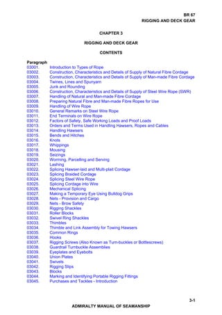
  • 24. BR 67 RIGGING AND DECK GEAR 03007. Handling of Natural and Man-made Fibre Cordage a. Elementary Rules. The lessons which a seaman must learn before handling a rope are explained below: (1) The Seaman’s Pocketknife. The seaman’s pocketknife is for issue to the Seaman Specialists sub branch only. It is supplied with a lanyard to enable the knife to be attached to a belt or belt loop and placed in the side or back pocket. The pocketknife is a tool and not a weapon and the edge of the blade should be sharpened like a chisel to avoid wearing away the thickness and strength of the blade, and the hinge should be kept lightly oiled. (2) Safety of Tools. Whenever seaman work aloft, or over the side, they must secure whatever tools they may be using with a lanyard secured to a part of the rigging or passed round their body. This is a common-sense precaution for avoiding possible injury to personnel working below or loss of the tools over the side. (3) Axe, Maul and Baulk of Timber. When working ropes during seamanship evolutions, an axe, maul and baulk of timber should be ready to hand to cut away ropes in an emergency. (4) Rope Ends. Before a rope is cut a whipping should be applied either side of the point at which the cut is to be made to prevent the rope unlaying. The different methods of whipping are described later in this chapter. (5) Coiling Down Ropes. A heaving-line, or any line or rope, which is being hauled in, should be coiled either in the hand or on the deck as it is hauled inboard. This is an elementary precaution to ensure that the line or rope is immediately ready for further use. b. Special Precautions When Handling Man-made Fibre Cordage. Although the rules for handling natural fibre cordage and man-made fibre cordage are generally similar, the properties and characteristics of man-made fibre necessitate greater care in its handling. Many of the advantages of using man-made fibre ropes can become serious liabilities if the seaman is not familiar with certain characteristics of these ropes. When a man-made fibre rope parts, it immediately tends to regain its original length. Polyamide when stretched over 40% is liable to part suddenly without audible warning and it then whips back along the line of tension and can kill or seriously injure anyone in its path. The following rules must be observed when handling man-made fibre ropes: (1) Personnel backing-up a man-made fibre rope under tension on a capstan drum or any other holding surface must stand well back and out of the line of recoil of the rope. Fig 3-12 shows the ideal position of personnel backing-up (B) a man- made fibre rope under tension (A), and the approximate angle (C), which is the ideal with respect to the line of recoil. 3-24 THE NAUTICAL INSTITUTE
  • 25. BR 67 RIGGING AND DECK GEAR Fig 3-12. Backing-up a Man-made Fibre Rope under Tension (2) When a man-made fibre rope is turned up on any holding surface, and is in tension, a certain amount of heat is generated by friction between the rope and the holding surface. Should this heat approach the melting point of the fibres of the rope, the outer fibre will melt and create a lubricant, whereupon the rope in tension may surge violently. It is essential therefore those personnel backing-up a man-made fibre rope in tension on a capstan drum, bollards or any holding surface must stand well back. The minimum distance between the first person backing-up the rope in tension and the holding surface should be two metres (Fig 3-12). Should the rope surge violently, this distance of two metres means that the first person backing-up will have some warning before being drawn dangerously close to the holding surface. (3) Ropes that have been subject to local permanent elongation, eg, towing hawsers, should be given time to recover to achieve their natural length if they are to be reeled up. Recovery time may be as long as six hours for a towing hawser that has been under heavy load for long periods. 3-25 ADMIRALTY MANUAL OF SEAMANSHIP
  • 26. BR 67 RIGGING AND DECK GEAR (4) Do not pass man-made fibre and steel wire ropes through the same fairlead. The stretch is incompatible and the resultant chafing of the man-made fibre will seriously weaken it. c. Handling All Cordage. From the precautions listed above for the safe handling of man-made fibre cordage, the following points should always be practised when handling any ropes or lines: (1) Avoid bad leads and sharp edges. Ensure thimbles or such fittings do not chafe or cut a rope. (2) As a general rule rope should be veered rather than surged on a capstan or winch drum because surging induces friction and damages the surface of the rope. However, surging the slip rope during the final stages of a replenishment is accepted practice as it enables the Receiving ship to readily match the speed at which the Delivering ship is recovering the replenishment rig. A rope should never be surged on a capstan or drum which is rotating in the same direction (turning to veer). This is a dangerous practice and applies to steel wire rope as well as fibre rope. (3) Three turns are usually sufficient when hawsers are being hove in on capstans or drum ends. However, for heavy loading it may be necessary to take an extra one or two turns, giving due regard to the size and strength of the rope and equipment involved. (4) If surging around bollards is necessary, it should be done before the strain on the rope is heavy. Great care must be taken when easing out a rope around bollards if it is heavily loaded. 03008. Preparing Natural Fibre and Man-made Fibre Ropes for Use a. Coiling and Uncoiling. A rope laid out straight will have no tendency to twist or turn either way, whether its lay is left- or right-handed, and from this position it can be stowed on a reel or coiled down. When stowed on a reel, or hauled off a reel, a rope will not develop any twists or turns in its length. When coiling down a rope however, the part of the rope remaining uncoiled will be given one twist or turn as each loop in the coil is formed. When coiling down a rope the end should be kept free to allow the uncoiled length to rotate and thus keep it free from becoming snarled up with kinks or turns. Similarly, a rope which is run off a coil will acquire a twist or turn for every loop in the coil, but if the end is kept free the rope will usually free itself of these turns when hauled out straight. One method of avoiding these turns, should the end of the rope not be free, is to turn the coil round while coiling down the rope, thus turning the coil into a reel. Another method, as when coiling direct from a reel, is to allow as long a length as possible between reel and coil; this length will absorb the turns until the end of the rope is free from the reel, and so can be freed of its turns. Similarly, when coiling down a rope which is led through a block, the coil should not be made too near the block, otherwise a slight check may cause a kink to develop in the rope as it is running through and thus choke the luff (Fig 3-13). 3-26 THE NAUTICAL INSTITUTE
  • 27. BR 67 RIGGING AND DECK GEAR b. Coiling Down (Fig 3-13). Cordage is very resilient and will absorb a number of turns in its length without becoming snarled if the length is sufficient and the turns correspond with the lay of the rope; if the turns are against the lay, however, it will quickly become snarled. For this reason, rope of right-hand lay is always coiled down right handed, and rope of left-hand lay is always coiled down left-handed. Fig 3-13. Mistakes in Coiling Down c. To Coil a Rope for Running (Fig 3-14). Lay the rope as straight as possible along the deck; begin coiling it down close to where the standing part is made fast, and lay each loop flat upon the other below it until the bare end is reached. The size of the loops should be as large as stowage space permits. The running part is now underneath the coil, so turn the coil over and the rope should then run out freely when required. Remember that the running part or end part should always be on top of any coil. Fig 3-14. To Coil a Rope for Running 3-27 ADMIRALTY MANUAL OF SEAMANSHIP
  • 28. BR 67 RIGGING AND DECK GEAR d. To Coil a Small Line in the Hand (Fig 3-15). When coiling in the right hand the rope should be held with the right thumb pointing towards the end; and when coiling in the left hand the thumb should point towards the bight. The coil will then form correctly. Fig 3-15. Coiling a Line e. To Thoroughfoot a Rope. This is the most effective way of taking a large number of turns out of a rope. First determine whether the turns to be removed are left- or right- handed. Then, to remove left-hand turns, coil down left-handed, dip the end through the coil and haul the coil out straight. To remove right-hand turns, coil down right- handed, dip the end through the coil and haul the coil out straight. If the bight of the rope is badly snarled, thoroughfoot the end for only a few metres at a time, repeating this operation as often as necessary. Thoroughfooting also describes the method of joining two ropes by their soft eyes (Fig 3-16). The eye of rope A is passed through the eye of rope B, and the bight of B is then hauled through the eye of A, thus joining the ropes by their eyes. This method is not used for joining two ropes temporarily, because it may take some time to unhitch them. Fig 3-16. Thoroughfooting 3-28 THE NAUTICAL INSTITUTE
  • 29. BR 67 RIGGING AND DECK GEAR f. To Fake Down a Rope (Fig 3-17). A rope that may have to be paid out quickly should be faked down in as long fakes as space allows. When faked, a rope does not acquire as many turns as when coiled and it will, therefore, run out with less chance of becoming snarled. Care should be taken that each bight at the end of a fake is laid under that immediately preceding it to ensure a clear run. Fig 3-17. Faking Down a Rope g. To Cheese Down a Rope (Fig 3-18). When a neat stow is required for a short end of rope, it may be cheesed down. This method should never be used when the rope will be required to render quickly through a block. Fig 3-18. Cheesing Down a Rope h. Belaying. When a rope will have to be cast off while still under strain it cannot be secured with a bend or a hitch, except perhaps a slipping one. It is therefore belayed to a fitting made for the purpose, such as a cleat, staghorn or bollard. The action of belaying consists of taking sufficient turns round the fitting to hold the rope by friction when it takes the strain. Generally speaking, four complete turns should be sufficient, but the number of turns may have to be increased according to the degree of friction existing between rope and fitting. A wet and slippery rope or bollard, or a smooth cleat or staghorn and a well-worn rope may require extra turns. i. To Belay a Rope to a Cleat or Staghorn. Take initial turns as shown in Fig 3-19, then continue with figure-of-eight turns round the horns of the cleat or staghorn as many times as required. It will be seen that when the figure-of-eight turns are removed the rope is ready to be checked under control. A rope belayed to a cleat or a staghorn must be ready for casting off at a moment’s notice; therefore the turns should not be completed with a half hitch, because this may jam them. Cleats are not suitable for belaying wire rope. 3-29 ADMIRALTY MANUAL OF SEAMANSHIP
  • 30. BR 67 RIGGING AND DECK GEAR Fig 3-19. Belaying a Rope to a Cleat or Staghorn j. To Hang a Coil on a Belaying Pin or Cleat (Fig 3-20 and Fig 3-21). Whenever possible a coil of rope should be hung up clear of the deck so as to keep the deck clear and the rope dry. Fig 3-20. Hanging a Small Coil on a Belaying Pin Fig 3-21. Hanging a Large Coil on a Cleat 3-30 THE NAUTICAL INSTITUTE
  • 31. BR 67 RIGGING AND DECK GEAR k. Making and Throwing a Heaving Line (Fig 3-22). (1) As its name implies, a heaving line is a light flexible line that can be thrown. It is used as a messenger to pass hawsers from ship to shore, or vice versa. Braidline of 8mm is very flexible and makes excellent heaving lines, although any similar size cordage can be used. A heaving line consists of approximately 30 metres of 8mm cordage. One end should be whipped and the other end weighted with a monkey’s fist (Fig 3-79), a small sandbag or a heaving line knot. WARNING HEAVING LINES MUST NOT BE WEIGHTED BY INSERTING A STEEL NUT OR LEAD WEIGHT INTO THE MONKEY’S FIST. NEITHER SHOULD THE MONKEY’S FIST BE PAINTED. (2) To prepare a heaving line for throwing, it should be wetted and between 22 and 24 metres should be coiled carefully in the non-throwing hand, using small coils. One third of the line is taken in the throwing hand; the line is then thrown with the throwing arm straight, and it must be allowed to run out freely from the coil in the non-throwing hand. The most frequent cause of bad casts is failure to have this coil properly clear for running. There is more than one method of heaving a line and most good throwers have their own variations. Some take rather less than half the coil in the throwing hand and throw both halves together, letting go with the throwing hand before the non-throwing hand. This method is very effective but harder to learn. Before heaving a line the standing end must be anchored between the thumb and index finger of the non-throwing hand. Never secure the standing end to the wrist or any other part of the body; the turning propellers make this a dangerous practice. As soon as the heaving line has been caught, the standing end or a bight of the line should be bent with a bowline to the eye of the hawser and not before. Every effort should be made to keep the line out of the water. Fig 3-22. Throwing a Heaving Line 3-31 ADMIRALTY MANUAL OF SEAMANSHIP
  • 32. BR 67 RIGGING AND DECK GEAR l. Handling New Cordage. (1) Opening a New Coil (Fig 3-23). A length of rope is supplied to a ship in a compact, machine-wound coil, bound with yarns or strands. To open up a new coil of rope of less than 48mm diameter, a seaman should roll it over until the outside end of the rope is at the top and pointing directly at him. The user should then turn the coil over towards their left and lay it flat on its side. The lashings are now cut and the inner end of the rope is pulled out from the centre (Fig 3-23). The rope will then leave the coil correctly and can then be coiled down. With rope of 48mm diameter or larger, the twisting involved in the preceding method is not acceptable and the coil must be unreeled in the opposite way to that in which it was made up. The coil should be placed on a turntable, or slung so that it can be revolved (Fig 3-23). Cut the lashings and haul the rope off from the outside. If this method is not possible, stand the coil on its end, and lap the rope off the top of the coil, turn by turn. As each turn is removed, revolve the end of the rope to take out twists. (2) Cutting off a Length of Rope from a New Coil. The required amount of rope is hauled from the coil, as previously described, and then the rope is whipped or taped at each side of the position at which it is to be cut. Whenever a length of rope is cut off a coil, a label, on which should be clearly stated either the length cut off or the length remaining should be attached to the coil. Fig 3-23. Opening a New Coil 3-32 THE NAUTICAL INSTITUTE
  • 33. BR 67 RIGGING AND DECK GEAR m. Storage of Cordage. Coils of new rope should be stowed clear of the deck, in a cool, well-ventilated, dry place, to allow the air to circulate freely around them. Used rope should be hung in loose coils if this is practicable. No cordage should be stowed in contact with bare steelwork. If cordage has to be stowed in the open it should be protected from sunlight because man-made fibres are susceptible to deterioration caused by the sun’s rays. 03009. Handling of Wire Rope Wire rope is much less resilient, and therefore much less tractable, than cordage. It resists being bent, does not absorb turns readily, and is therefore much more liable to kinking and snarling, and tends to spring out of a coil, or off a drum or bollard. If handled correctly however, it can be used for most of the purposes to which cordage is put, but bends and hitches should not be made in it. a. Kinking and Crippling. Because of its construction and comparative lack of flexibility, wire rope requires more care in handling than cordage; if carelessly handled it may suffer serious damage through kinking and crippling. (1) Kinking. Any loop or turn in a wire rope can all too easily be pulled into a kink, which permanently damages it. If a kink is seen to be about to develop it should be removed as indicated in Fig 3-24 and no attempt should be made to pull it out in the manner shown in Fig 3-25. Fig 3-24. The Right Way to Remove a Kink in Wire Rope Fig 3-25. The Wrong Way to Remove a Kink in Wire Rope 3-33 ADMIRALTY MANUAL OF SEAMANSHIP
  • 34. BR 67 RIGGING AND DECK GEAR (2) Crippling (Bad Nips) (Fig 3-26). If a wire rope is bent at too acute an angle, or led over a sharp edge, it will be seriously damaged by distortion of its strands, which may result in a permanent kink or even in the rope parting. A rope so led is said to form a bad nip and this results in it being crippled. (To freshen the nip is to veer or heave in a short length of rope that is under strain so as to bring a fresh portion of the rope to take the chafe where it passes through fairleads or around bollards). To prevent crippling, a wire rope, which will come under strain, should never be led through a shackle or eyeplate to alter the direction of its lead. In addition, it should not be round a bollard or drum of a diameter less than thirteen times the diameter of the rope; and if it has to run through a block, the diameter of the sheaves should be at least twenty times the diameter of the rope. Fig 3-26. Examples of Bad Nips (Leads) b. Coiling and Uncoiling. Wire rope, especially long lengths of it, should be stowed on reels, but where this is not practicable it must be coiled down. Wire rope is less able to absorb turns than fibre rope; when coiling down it is therefore all the more necessary to have the uncoiled length free to revolve. Where this is impossible, an alternative is to use left-handed loops, called Frenchmen, in the coil (Fig 3-27). These Frenchmen serve to counteract the twists put in by coiling down right-handed. Frenchmen are also necessary when coiling down a wire rope of which some portions have contracted a left-hand set (as will occur when a rope belayed left-handed round a bollard has been subjected to strain). Such portions will resist being coiled right- handed and each loop must be allowed to become a Frenchman. It is wise to stand clear when rope is being hauled off a coil containing Frenchmen; as such turns are very likely to jump off. A coil of wire rope should always be well stopped to prevent the coils from springing out of place. The best way to run out a coiled down wire is shown in Fig 3-28. 3-34 THE NAUTICAL INSTITUTE
  • 35. BR 67 RIGGING AND DECK GEAR Fig 3-27. A Frenchman Fig 3-28. Running Out a Coiled Down Wire c. Handling New Steel Wire Rope. (1) To Unreel or Uncoil a New Rope. New wire ropes are supplied either in machine wound coils or on cable drums (reels). They must be taken off the coils or drums in the correct manner, or kinks will quickly develop. A small coil can be rolled along the deck, but if space does not permit, or the rope is heavy, place the coil on a turntable and lash down two strong battens crosswise on the top of the coil (Fig 3-29). This will prevent the rope springing up over the top of the coil and kinking. Then cut the stops, and haul the rope off the coil as it rotates on the turntable. Fig 3-29. Uncoiling a New Wire Rope 3-35 ADMIRALTY MANUAL OF SEAMANSHIP
  • 36. BR 67 RIGGING AND DECK GEAR (2) To unreel the rope from a drum, pass a shaft through the drum and support the shaft at either end, thus allowing the drum to revolve; then cut the outer stops and unreel the rope off the drum (Fig 3-30). To coil down a small rope from a drum, up-end the drum as shown in Fig 3-31, and lap the rope off the top of the drum, lapping off each turn anti-clockwise. The twist put in the rope as each turn is lapped off is cancelled automatically by coiling the rope down clockwise. Fig 3-30. Unreeling a New Wire Rope Fig 3-31. Lapping Off and Coiling Down a Small Wire Rope (3) To Cut Off a Length of Wire Rope. The rope should be very firmly whipped about 25mm on each side of the position at which it is to be cut, then placed on the top of a bollard or similar hard surface. The strands should then be cut with a hammer and cold chisel or with a wire-cutter. Whenever a length of rope is cut off a coil or a drum, the coil or drum should be clearly marked, indicating either the length cut off or the length remaining. 3-36 THE NAUTICAL INSTITUTE
  • 37. BR 67 RIGGING AND DECK GEAR d. Care and Maintenance of Steel Wire Rope. Wire ropes have a lubricant incorporated during manufacture. This serves a dual purpose; it provides corrosion protection and also minimises internal friction. The protection provided by this manufacturing lubricant is normally adequate to prevent deterioration due to corrosion during the early part of a rope’s life. However, the lubricant applied during manufacture must be supplemented by lubrication in service. This lubrication is termed the ‛dressing’. The kind of dressing used and the frequency of application vary with the type of rope and its usage. Details of the maintenance of steel wire rope carried by, or fitted in HM ships are laid down in the Maintenance Management in Ships system (MMS). Wire hawsers should be stowed on reels under a fitted cover whenever possible. When being reeled in or otherwise stowed, the surface of a wire hawser should be washed with fresh water to free it from salt, then dried with cloths and lightly smeared with the appropriate lubricant. e. Inspecting Steel Wire Rope. Steel wires ropes carried or fitted in HM ships must be inspected periodically in accordance with the MMS system. When inspecting, the indications described below should be sought: (1) Distortion of Strands. This is the result of damage by kinking, crushing, serious crippling round a bad nip, or other mistreatment. If likely to cause the strands to bear unequal stresses, they must be considered as reducing the strength of the rope by 30%; and should they be sufficiently serious to cause the heart to protrude, the rope must be discarded. A crushed rope may be restored to some extent by the careful use of a mallet. (2) Flattening of Some of the Outer Wires by Abrasion. These flats are easily seen because the abrasion gives the flattened wires a bright and polished appearance, but they do not affect the strength of the rope unless they are very pronounced. Flats, which extend to three-quarters of the diameter of the wires, will reduce their cross-sections - and therefore their individual strengths - by 10%, and as only a limited number of wires will be affected the loss in strength of the whole rope will be very small. (These flats must not be confused with flattening of the whole rope, which indicates distortion of the strands and is therefore much more serious). (3) Broken Wires. These are usually the result of fatigue and wear, and mostly occur in crane wires. It is generally accepted that a wire rope is coming to the end of its useful life when one wire of any strand breaks. To deal with a broken wire, grip the broken end with a pair of pliers and bend the wire backwards and forwards until the wire breaks inside the rope between the strands, where it can do no harm. A rope should be discarded if more than 5% of its wires are broken in a length equal to ten times the diameter of the rope; for example a 24mm diameter, 6X24 wire rope should be discarded if seven broken wires are found in a length of 240mm. Because of the danger to handlers, berthing wires should be discarded if any broken wires are discovered. (4) Corrosion. Wire rope can be corroded by: (a) The action of damp on the wires from which the galvanising has worn off; if this occurs to the inner wires first it causes rust to fall out of the rope and is therefore easily detected. (b) The action of fumes and funnel gases, which attack the outside wires, the effect then becomes visible on inspection. 3-37 ADMIRALTY MANUAL OF SEAMANSHIP
  • 38. BR 67 RIGGING AND DECK GEAR (c) Contact with acid, which soaks into the heart and attacks the inside wires; this is not necessarily noticeable on the outside of the rope, and can be the cause of parting without warning. (5) Lack of lubrication is a frequent cause of corrosion. When a wire rope is under tension it stretches and becomes thinner, and during this process the individual wires are compressed and friction is set up; the fibre heart and cores are also compressed, releasing oil to overcome the friction. A wire rope of outwardly good appearance, but with a dry powdery heart or core, has not been properly maintained and should be treated with caution. (6) Effect of Extreme Cold. When subjected to extreme cold a wire rope may become brittle and lose its flexibility, and an apparently sound rope may part without warning. The brittleness is not permanent and the rope will regain its resilience in a normal temperature, but the potential danger should be remembered when working wires in very cold climates. f. Testing of Steel Wire Rope. The wire from which the rope is to be made is tested before manufacture of the rope to ensure it complies with the relevant British Standards Specification with regard to tensile strength, torsion and galvanising properties. After manufacture of each production length of rope, test samples are cut from the finished rope and strand. These samples are used for a tensile test to destruction, tests of preforming of the rope, and tests on a mixture of the individual wires with regard to diameter, tensile strength, torsion and quality of galvanising. A certificate of conformity and a test certificate showing the guaranteed minimum breaking strength of the wire when new accompany each coil of wire. 03010. General Remarks on Steel Wire Rope a. How to Measure the Size of a Rope. The size of a wire rope is the diameter in millimetres of a true circle, which will just enclose all the strands (Fig 3-32). Measure at each of three places at least two metres apart. The average of these measurements is to be taken as the diameter of the rope. Fig 3-32. How to Measure the Diameter of a Rope 3-38 THE NAUTICAL INSTITUTE
  • 39. BR 67 RIGGING AND DECK GEAR b. Sheaves for Wire Rope. (1) Size of Sheave Required for a Wire Rope Hoist. The diameter of sheave required for each type of six-strand wire rope supplied to the Royal Navy should be at least twenty times the diameter of the wire. The diameter of a sheave used for any wire rope will considerably affect the life of that rope. As the rope bends round a sheave the strands and wires farthest from the centre of curvature move apart and those nearest the centre of curvature move closer together. This results in the generation of considerable friction between these wires and strands, and the smaller the sheave the greater will be the friction. Friction also increases rapidly with the speed at which the rope is moving. While the rope is bent round a sheave the outer wires are also subjected to a marked additional stress, and the smaller the diameter of the sheave the greater will be the stress. For these reasons the minimum diameters of sheaves recommended from practical experience for various types of ropes at speeds not exceeding 60 metres per minute are twenty times the diameters of the ropes. For each increase in speed of 30 metres per minute, 5% must be added to these figures; this will give a rope a reasonable life, but it is emphasised that its life will be greatly increased if still larger sheaves are used. Similarly, if a smaller sheave than that recommended has to be accepted, it will shorten the life of the rope, and on no account should a sheave be used that is more than 20% smaller than that determined by reference to the above criteria. (2) Use of Correct Sheave. The life of a rope used for hoisting can also be considerably shortened by using the wrong type of sheave. The groove in the sheave must fit and support the rope as it travels round the sheave, otherwise there will be increased internal friction and external wear. Fig 3-33(i) shows a sheave with too wide a groove, which results in a flattening of the rope and considerable distortion and internal friction. Fig 3-33(ii) shows a sheave with too narrow a groove, which results in the rope not being supported, the wires of the strands being subjected to considerable wear, and friction being set up between the rope and the sides of the groove. The groove of the correct sheave should be shaped in cross-section to the true arc of a circle for a distance equal to one-third of the circumference of the rope, and the radius of the groove should be 5-10% greater than the specified radius of the rope (Fig 3-34). Fig 3-33. Examples of Incorrect Sheaves for Wire Rope 3-39 ADMIRALTY MANUAL OF SEAMANSHIP
  • 40. BR 67 RIGGING AND DECK GEAR Fig 3-34. Diagrammatic Example of a Correct Sheave for Wire Rope 03011. End Terminals on Wire Rope a. Besides the soft, thimble and hawser eyes, other kinds of terminals are used for the ends of wire rope and some of them are explained below. b. Sockets. There are several types of socket (Fig 3-35(i)) but a standard method of attaching them to the end of a wire. The wires at one end of the rope are fluffed out like a shaving brush to fill the hollow conical head of the socket, the ends of the wire are then hooked over towards the centre and molten white metal is poured in to make the whole head solid. This skilled work is normally done by qualified dockyard personnel. A well-made socket should have the strength of the rope but the rope is subject to fatigue where it enters the socket because of the abrupt loss of flexibility. Frequent examination is essential and if a single broken wire is seen near the socket the rope should be recapped without delay. c. Swaged Terminals are a modern alternative to the sockets described above, and as with the socket there are various types. The end of the wire is inserted in the terminal and both are placed in a special swaging machine in which the terminal is hydraulically compacted on to the rope. This process, which is carried out cold, does not affect the temper or strength of the rope. 3-40 THE NAUTICAL INSTITUTE