Difference b/w STP RSTP PVST & MSTP
•
11 gefällt mir•30,641 views

Difference between Spanning Tree Protocol (STP) and Rapid Spanning Tree Protocol (RSTP) 1. The main difference between Rapid Spanning Tree Protocol (RSTP IEEE 802.1W) and Spanning Tree Protocol (STP IEEE 802.1D) is that Rapid Spanning Tree Protocol (RSTP IEEE 802.1W) assumes the three Spanning Tree Protocol (STP) ports states Listening, Blocking, and Disabled are same (these states do not forward Ethernet frames and they do not learn MAC addresses). Hence Rapid Spanning Tree Protocol (RSTP IEEE 802.1W) places them all into a new called Discarding state. Learning and forwarding ports remain more or less the same.

Empfohlen
Weitere ähnliche Inhalte
Was ist angesagt?
Was ist angesagt? (20)
Ähnlich wie Difference b/w STP RSTP PVST & MSTP
Ähnlich wie Difference b/w STP RSTP PVST & MSTP (20)
Mehr von Netwax Lab
Mehr von Netwax Lab (20)
Kürzlich hochgeladen
Kürzlich hochgeladen (20)
Difference b/w STP RSTP PVST & MSTP
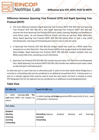
- 1. Difference b/w STP, RSTP, PVST & MSTP Difference between Spanning Tree Protocol (STP) and Rapid Spanning Tree Protocol (RSTP) 1. The main difference between Rapid Spanning Tree Protocol (RSTP IEEE 802.1W) and Spanning Tree Protocol (STP IEEE 802.1D) is that Rapid Spanning Tree Protocol (RSTP IEEE 802.1W) assumes the three Spanning Tree Protocol (STP) ports states Listening, Blocking, and Disabled are same (these states do not forward Ethernet frames and they do not learn MAC addresses). Hence Rapid Spanning Tree Protocol (RSTP IEEE 802.1W) places them all into a new called Discarding state. Learning and forwarding ports remain more or less the same. 2. In Spanning Tree Protocol (STP IEEE 802.1D), bridges would only send out a BPDU when they received one on their Root Port. They only forward BPDUs that are generated by the Root Switch (Root Bridge). Rapid Spanning Tree Protocol (RSTP IEEE 802.1W) enabled switches send out BPDUs every hello time, containing current information. 3. Spanning Tree Protocol (STP IEEE 802.1D) includes two port types; STP Root Port and Designated Port. Rapid Spanning Tree Protocol (RSTP IEEE 802.1W) includes two additional port types called as alternate ports and backup ports. An alternate port is a port that has an alternative path or paths to the Root Switch (Root Bridge) but is currently in a discarding state (can be considered as an additional unused Root Port). A backup port is a port on a network segment that could be used to reach the root switch, but there is already an active STP Designated Port for the segment (can be considered as an additional unused designated port). Table View STP (802.1d) Rapid STP (802.1w) In stable topology only the root sends BPDU and relayed by others. In stable topology all bridges generate BPDU every Hello (2 sec) : used as“keepalives” mechanism. Port states Disabled Blocking Listening Learning Forwarding Discarding (replaces disabled, blocking and listening) Learning Forwarding
- 2. Difference b/w STP, RSTP, PVST & MSTP To avoid flapping, it takes 3 seconds for a port to migrate from one protocol to another (STP / RSTP) in a mixed segment. Port roles Root (Forwarding) Designated (Forwarding) Non-Designated (Blocking) Root (Forwarding) Designated (Forwarding) Alternate(Discarding)Backup (Discarding) Additional configuration to make an end node port aport fast (in case a BPDU is received). - An edge port (end node port) is an integrated Link type which depends on the duplex : Point-to-point for full duplex & shared for half duplex). Topology changes and convergence Use timers for convergence (advertised by the root): Hello(2 sec) Max Age(20 sec = 10 missed hellos) Forward delay timer (15 sec) - Introduce proposal and agreement process for synchronization (< 1 sec).- Hello, Max Age and Forward delay timer used only for backward compatibility with standard STP Only RSTP port receiving STP (802.1d) messages will behaves as standard STP. Slow transition (50sec): Blocking (20s) =>Listening (15s) =>Learning (15s) =>Forwarding Faster transition on point-to-point and edge ports only:Less states – No learning state, doesn’t wait to be informed by others, instead, actively looks for possible failure by RLQ (Request Link Query) a feedback mechanism. Use only 2 bits from the flag octet:Bit 7 : Topology Change Acknowledgment.Bit 0 : Topology Change Use other 6 bits of the flag octet (BPDU type 2/version 2): Bit 1 : ProposalBit 2, 3 : Port roleBit 4 : LearningBit 5 : ForwardingBit 6 : AgreementBit 0, 7 : TCA & TCN for backward compatibility The bridge that discover a change in the network inform the root, that in turns informs all others by sending BPDU with TCA bit set and instruct them to clear their DB entries after “short timer” (~Forward delay) expire. TC is flooded through the network, every bridge generate TC (Topology change) and inform its neighbors when it is aware of a topology change andimmediately delete old DB entries.
- 3. Difference b/w STP, RSTP, PVST & MSTP If a non-root bridge doesn’t receive Hello for 10*Hello (advertised from the root), start claiming the root role by generating its own Hello. Wait for 3*Hello on a root port (advertised from the root) before deciding to act. Wait until TC reach the root + short timer (~Forward delay) expires, then flash all root DB entries Delete immediately local DB except MAC of the port receiving the topology changes (proposal) Difference between PVST+ (Per VLan Spanning Tree) & MST (Multiple Spanning Tree) 1. PVST+ (Per VLan Spanning Tree)- It's difference from 802.1Q CST because instead of having a single root switch for all VLAN, The PVST+ mean STP is run in each VLAN. 2. MST (Multiple Spanning Tree)- MST maps multiple VLANs into a spanning tree instance, with each instance having a spanning tree topology independent of other spanning tree instances.This architecture provides multiple forwarding paths for data traffic, enables load balancing, and reduces the number of STP instances required to support a large number of VLANs. MST improves the fault tolerance of the network because a failure in one instance (forwarding path) does not affect other instances (forwarding paths).