SlideShare ist ein Scribd-Unternehmen logo
1 von 12
1
Rice Transporter Robot
Project Report
By Kristopher Brown
CAD/CAM
Dr. Michael Greminger
Spring Semester 2015
2
Table of Contents
Design Summary.........................................................................................3
Hopper .............................................................................................3
Motor plates......................................................................................3-4
Rack and Stilt Assembly....................................................................4
Rollers ..............................................................................................5
Bill of Materials ..........................................................................................6
Finite Element Analysis Setup.....................................................................7
Determining Volume and Load..........................................................7
Applying Loads and Constraints ........................................................7
Remote Load/Mass..................................................................7-8
Reaction Force........................................................................8
Finite Element Analysis Results ..................................................................9
Uniform Thickness............................................................................9
Multiple Thicknesses.........................................................................9-10
Confirming Finite Element Analysis...................................................11
Conclusion .................................................................................................12
3
Design Summary
The main goal for the project was to maximize the carrying capacity of the hopper and minimize the material
needed to structurally survive the required load with a displacement less than 0.5 mm. My design includes
features that cater to both of these requirements while also considering the ease for assembly by the assembler.
Hopper:
The hopper is printed with multiple different thicknesses that optimize the displacement when under load. In
order to reduce the unsymmetrical deformation the hopper experiences at max load, the thickness of the walls
range from 2.28mm to 2.49 mm thick seen in figure 1.
Figure 1: Top View of Hopper with Thicknesses
Motor Plates:
The upper and lower motor plates are of simple design. They are CNC threaded, and are machined from only
one side which can be seen in figures 2 and 2.1. The blue circles on figure 2 represent where the plates fasten to
the hopper and the red circles represent the threaded holes that are used to attach the motor to the plates.
Figure 2 (left): Front View of Motor Plates Figure 2.1 (right): Top View of Motor Plates
4
The grooves machined into the plates allow for a snug fit with the motor. The design intends that the motor will
be first fastened to the upper and lower plates before both plates are attached to the hopper.
Rack and Stilt Assembly:
Figure 3 (left): Front View of Rack and Stilt
Figure 3.1 (center): Side View of Rack and Stilt
Figure 3.2 (right): T-shape end attaching HUB-ee Wheels to Rack and Stilt
The rack and stilt assembly are fastened together by two hex nuts represented by the green circles in figure 3.
The stilt is threaded allowing for a tight assembly. To convert the rotational work done by the motor to linear
motion of the rack and stilt, the motor pinion gear is tangent to the rack. The HUB-ee Wheels are fastened to the
rack by pegs that are designed specifically for the ‘cross’ extrusion cut in the wheels. These pegs are made out
of aluminum and will need to be CNC machined due to their groove radius of 0.5mm.
Included in the hopper design are sliding brackets that support the upper and lower parts of the rack and stilt
assemblies. They have clearances for the rack addendum and help resist rotational and bending deformations of
the racks and stilts that may occur during loading.
Figure 4: Top View of Bracket Figure 4.1: Isometric View of Upper Brackets
5
Figure 4.2: Front View of Lower Brackets
Rollers:
The transporter robot has rollers that help support its center of gravity when transitioning from the ground to the
top of the 20 centimeter clearance. My design, which can be seen in figures 5 and 5.1, consists of a tri-sectioned
roller design that is held and secured by 1.50 mm tabs. The reason I went with this tri-section design was
because I wanted to have multiple support points in the middle as well as on ends of the hopper.
Figure 5: Bottom View of Rollers Figure 5.1: Isometric View of Rollers and E-style ring
6
Bill Of Materials (BOM)
Item
#
Part Name Manufacture Method Material
Quanti
ty
1 Hopper 3D Printed ABS 1
2 GW370 Motor Provided by Sumotor Zinc Alloy 2
3 Pinion Gear Provided by Manufacturer Aluminum 6
4 Teflon roller Provided by Manufacturer PTFE 12
5 Roller Shaft Provided by Manufacturer Steel 4
6 Reinforced E-style Retaining Ring SolidWorks Design Library Alloy Steel 8
8 Lower Motor Plate CNC (threaded) Aluminum 2
9 Upper Motor Plate CNC (threaded) Aluminum 2
10 B18.6.7M - M3 x 0.5 x 10 Indented HMS --10N SolidWorks Design Library SolidWorks Design Library 19
11 B18.6.7M - M3 x 0.5 x 13 Indented HMS --13S SolidWorks Design Library SolidWorks Design Library 17
12 B18.6.7M - M3 x 0.5 x 4 Indented HHMS --4N SolidWorks Design Library SolidWorks Design Library 8
13 B18.6.7M - M3 x 0.5 x 8 Indented HHMS --8N SolidWorks Design Library SolidWorks Design Library 16
14 Upper Sliding Bracket CNC (threaded) Plastic 8
15 Clamping Sliding Bracket CNC (threaded) Plastic 8
16 Pinion Shaft CNC Steel 2
17 B18.2.4.1M - Hex nut, Style 1, M3 x 0.5 --D-N SolidWorks Design Library SolidWorks Design Library 28
18 Rack Waterjet cut Plastic 4
19 Stilt Waterjet cut Aluminum 4
20 HUB-ee Wheels Provided by Manufacturer Provided by Manufacturer 4
21 HUB-ee Pegs CNC Aluminum 4
Table 1: Rice Transporter Robot Bill of Materials
7
Finite Element Analysis Setup
Determining Volume and Load:
After completing the assembly of the rice transporter robot, I isolated the hopper component to calculate the
internal volume. This internal volume is the deciding factor on the rice carrying capacity of the hopper. To do
this, I suppressed all the holes, and created a surface to cover the hopper. The hopper was then broken into two
regions, creating default and volume configurations that can be found in the SolidWorks hopper part. Using the
mass properties solver in SolidWorks, I found the initial volume before optimization to be 11,335,724.44 mm3.
The density value used for dry rice (7.82x10⁻⁷ kg/m3) was obtained from aqua-calc.com. From these two values,
I was able to find the weight by multiplying the mass of 8.8645 kg by gravity (9.81 m/s2). This calculation can
be seen in figure 7 below.
Figure 7: Calculating the Load
Applying Loads and Constraints:
I opened a static analysis in SolidWorks and began applying loads and constraints to the hopper. The total rice
load of 86.961 N was applied uniformly to the bottom faces of the hopper, which can be seen in figure 7.1
below. All thickness trials were performed without the change of this load respective to the volume of the
hopper, reducing the amount of iterations needed in order to optimize the design.
Figure 7.1: Findingthe
Load
8
Remote Load/Mass:
To represent the force of each motor, a remote load was applied to the holes used for fastening the upper and
lower motor plates to the hopper, see figure 8 and 8.1 below. In order to properly define this load, global
coordinates were made at the contact point between the motor powered pinion gear and the rack. In my
assembly, the y-axis is up, the z-axis is normal to the face of the hopper, and the x-axis is adjacent to the
hopper. For one motor, all translation axes were set to zero. The opposing motor only had the x-and-y
translations set to zero, because I wanted to restrict the rotation displacement without over constraining the
analysis.
Figure 8 (left): All three axes (x,y,z) translations set to zero
Figure 8.1 (right): Two axes (y,z) translations set to zero
Reaction Force:
A ‘fixed geometry fixture’ constraint was placed on the two concentric shaft bearing holes that connect the
motorized pinions to their opposing counterparts. This constraint simulates the reaction force of the connecting
shaft acting on the hopper when load is applied. To do this, I applied a split line to the bearing holes shown in
figure 9 below.
Figure 9: Pinion Shaft Reaction Force Surface
9
Finite Element Analysis Results
Uniform Thickness:
Before performing the static analysis, I created a 7 mm fine curved base so the hopper could run properly. The
first trial analyzed the initial uniform hopper thickness of 2mm and obtained a displacement result of 0.686 mm
that can be seen in figure 10 and 10.1 below.
Figure 10: 0.686 mm displacement Figure 10.1: 3.905 MPa Max annotation
The max annotation stress shown in figure 10.2 is 3.905 MPa. The tensile strength of ABS is 13 MPa, which
means that the factor of safety of my design is around 3.329. This is more than twice the design requirement of
a 1.5 factor of safety.
Multiple Thicknesses:
With the displacement result of the uniform thickness trial being 0.186mm over the threshold of the 0.5 mm
displacement design constraint, I decided to use the multiple thickness shell feature to reinforce specific
sections of my hopper. I selected four faces. I set a thickness of 2.28mm for the top face, 2.41mm to the max
displaced face, 2.4mm to the one adjacent to it, and 2.35 mm to the bottom face.
Figures 11 and 11.1: Views of multi-thickness faces
10
The result from the multi-thickness hopper was a displacement of 0.5144 mm which can be seen from figure 12.
This showed that the multi-thickness feature helped in reducing the displacement experienced by the whole
hopper.
Figure 12: Multiple Thickness Trial 1
With this data, I was able to better determine the increase of thicknesses needed to reinforce the hopper. I
decided to increase the thicknesses as follows: top face maintained at 2.28 mm, the max displaced face from
2.41 to 2.49 mm, adjacent face from 2.4 to 2.46 mm, and maintained the bottom face at 2.40 mm. The change in
thickness size resulted in a displacement of 0.4997 mm which is below the design threshold of 0.5 mm
displacement seen in figure 13. The stress plot max annotation resulted in 3.425 MPa, which is a factor of safety
of 3.796, more than twice the design requirement seen in figure 13.1.
Figure 13: Displacement of 0.4997 mm Figure 13.1: 3.425 MPa stress max annotation
This optimized design resulted in a volume of 11,238,169.27 cubic millimeters.
11
Confirming Finite Element Analysis:
To confirm the reaction force on the pinion shaft holes, I performed a stress hand calculation that can be seen in
figure 14. For the calculation, it was assumed that the reaction force of 63.7 N is distributed between the two
holes, so 31.851 N was used for the force of one bearing hole.
Figure 14: Stress at Shaft Hole
Using the probe feature in the stress plot, I selected the split line plane for the hole and received a stress result
of 2.344 MPa. This value is very similar to the hand calculation, solidifying the bearing holes were set up
correctly.
Figure 14.1: Reaction Stress
To determine if the whole finite element analysis was correct, I confirmed the force applied by the remote
load/mass of the motors and the upward reaction force from the pinion shaft bearing holes by adding them
together. Their total equaled the initial load of 86.961 N which can be seen in figures 15 and 15.1 below.
Figure 13 (left): Reaction Force Values Figure 15.1 (right): Remote Load/Mass Force
12
Conclusion:
My final design resulted in a displacement of 0.4997 mm when under an 86.931 N load and holds
11,238,169.27 of dry rice. The design is simplistic, and easy to assemble. If I was able to lift some of the
manufacturing constraints, I would design a hopper that was made up of multiple sections instead of one part.
This way, I could create each section of the hopper using the current envelope size of 8x8x12 inches. It could
potentially increase the carrying capacity by about four times the current volume. Also, if the 250 mm wide
envelope design constraint would be waived, I would’ve not created the wheel wells.
If I was able to work on the design further, I would create the brackets to push the stilts out a bit a more. When
designing, I was cautious on how wide my final design would be. I ended up being 4.8 mm short of the 250 mm
constraint. This was a missed opportunity in maximizing the volume. I would also make the brackets more
supportive and robust in order to support the stilt/rack assemblies in this change. Along with this, I would
increase the thickness of the motor plates to allow the motor to be fastened farther away from the hopper. This
would reduce the displaced volume of the motor relative to the hopper. As far as the multi-thickness changes
go, I did a lot of guess and check for this design. I would take more time or perform a design study next time to
make sure that every thickness addition to the hopper was optimal.

Weitere ähnliche Inhalte

Was ist angesagt?

Ts 17 halfshafts-and-tripods
Ts 17 halfshafts-and-tripodsTs 17 halfshafts-and-tripods
Ts 17 halfshafts-and-tripodsStefan Radulovic
 
IRJET- Design Analysis and Optimization of Two-Wheeler Chassis for Weight Red...
IRJET- Design Analysis and Optimization of Two-Wheeler Chassis for Weight Red...IRJET- Design Analysis and Optimization of Two-Wheeler Chassis for Weight Red...
IRJET- Design Analysis and Optimization of Two-Wheeler Chassis for Weight Red...IRJET Journal
 
weight optimization of lathe bed using FEA
weight optimization of lathe bed using FEAweight optimization of lathe bed using FEA
weight optimization of lathe bed using FEACollege
 
Design, Development & Analysis of Loopwheel Technology
Design, Development & Analysis of Loopwheel TechnologyDesign, Development & Analysis of Loopwheel Technology
Design, Development & Analysis of Loopwheel TechnologyABHISHEKPUND
 
BAJA 2013 final year project report
BAJA 2013 final year project reportBAJA 2013 final year project report
BAJA 2013 final year project reportKalyan Potukuchi
 
Formula 1000 Frame Design
Formula 1000 Frame DesignFormula 1000 Frame Design
Formula 1000 Frame Designdmcmah0n
 
6.2 dd-guest room 1
6.2 dd-guest room 16.2 dd-guest room 1
6.2 dd-guest room 1VOBAOTOAN
 
NMSU_Design_Report_2016
NMSU_Design_Report_2016NMSU_Design_Report_2016
NMSU_Design_Report_2016Arthur Cox
 
5)structural performance analysis of formula sae car
5)structural performance analysis of formula sae car5)structural performance analysis of formula sae car
5)structural performance analysis of formula sae carAnkit Singh
 
Micro headroom JIB CRANE
Micro headroom JIB CRANEMicro headroom JIB CRANE
Micro headroom JIB CRANEDouble Gear
 
Conveyor handbook-pdf
Conveyor handbook-pdfConveyor handbook-pdf
Conveyor handbook-pdfmkpq pasha
 
4 simple, cheap tools for Africa
4 simple, cheap tools for Africa 4 simple, cheap tools for Africa
4 simple, cheap tools for Africa Emeka_Okafor
 
Design & Construction of a Connecting rod
Design & Construction of a Connecting rodDesign & Construction of a Connecting rod
Design & Construction of a Connecting rodFaisal Niloy
 
Design of half shaft and wheel hub assembly for racing car
Design of half shaft and wheel hub assembly for racing carDesign of half shaft and wheel hub assembly for racing car
Design of half shaft and wheel hub assembly for racing carRavi Shekhar
 
base plate in bending and anchor bolts in tension
base plate in bending and anchor bolts in tensionbase plate in bending and anchor bolts in tension
base plate in bending and anchor bolts in tensionabdul latief
 

Was ist angesagt? (20)

MVS1A
MVS1AMVS1A
MVS1A
 
Ibc ball screw support bearings
Ibc ball screw support bearingsIbc ball screw support bearings
Ibc ball screw support bearings
 
Ts 17 halfshafts-and-tripods
Ts 17 halfshafts-and-tripodsTs 17 halfshafts-and-tripods
Ts 17 halfshafts-and-tripods
 
Chassis design for baja sae
Chassis design for baja saeChassis design for baja sae
Chassis design for baja sae
 
IRJET- Design Analysis and Optimization of Two-Wheeler Chassis for Weight Red...
IRJET- Design Analysis and Optimization of Two-Wheeler Chassis for Weight Red...IRJET- Design Analysis and Optimization of Two-Wheeler Chassis for Weight Red...
IRJET- Design Analysis and Optimization of Two-Wheeler Chassis for Weight Red...
 
weight optimization of lathe bed using FEA
weight optimization of lathe bed using FEAweight optimization of lathe bed using FEA
weight optimization of lathe bed using FEA
 
Design, Development & Analysis of Loopwheel Technology
Design, Development & Analysis of Loopwheel TechnologyDesign, Development & Analysis of Loopwheel Technology
Design, Development & Analysis of Loopwheel Technology
 
BAJA 2013 final year project report
BAJA 2013 final year project reportBAJA 2013 final year project report
BAJA 2013 final year project report
 
Formula 1000 Frame Design
Formula 1000 Frame DesignFormula 1000 Frame Design
Formula 1000 Frame Design
 
6.2 dd-guest room 1
6.2 dd-guest room 16.2 dd-guest room 1
6.2 dd-guest room 1
 
NMSU_Design_Report_2016
NMSU_Design_Report_2016NMSU_Design_Report_2016
NMSU_Design_Report_2016
 
5)structural performance analysis of formula sae car
5)structural performance analysis of formula sae car5)structural performance analysis of formula sae car
5)structural performance analysis of formula sae car
 
Micro headroom JIB CRANE
Micro headroom JIB CRANEMicro headroom JIB CRANE
Micro headroom JIB CRANE
 
Conveyor handbook-pdf
Conveyor handbook-pdfConveyor handbook-pdf
Conveyor handbook-pdf
 
4 simple, cheap tools for Africa
4 simple, cheap tools for Africa 4 simple, cheap tools for Africa
4 simple, cheap tools for Africa
 
Design & Construction of a Connecting rod
Design & Construction of a Connecting rodDesign & Construction of a Connecting rod
Design & Construction of a Connecting rod
 
Design of half shaft and wheel hub assembly for racing car
Design of half shaft and wheel hub assembly for racing carDesign of half shaft and wheel hub assembly for racing car
Design of half shaft and wheel hub assembly for racing car
 
base plate in bending and anchor bolts in tension
base plate in bending and anchor bolts in tensionbase plate in bending and anchor bolts in tension
base plate in bending and anchor bolts in tension
 
780059
780059780059
780059
 
780059
780059780059
780059
 

Andere mochten auch

Ficha de antecipação da história (ilustração) um pé de vento
Ficha de antecipação da história (ilustração)   um pé de ventoFicha de antecipação da história (ilustração)   um pé de vento
Ficha de antecipação da história (ilustração) um pé de ventolidiacosta
 
Orpheus Looks Back
Orpheus Looks BackOrpheus Looks Back
Orpheus Looks BackSam Ryan
 
contoh Rph kepelbagaian pelajar
contoh Rph kepelbagaian pelajarcontoh Rph kepelbagaian pelajar
contoh Rph kepelbagaian pelajarfarhana86
 
Plant meristem temperatures
Plant meristem temperaturesPlant meristem temperatures
Plant meristem temperaturesAndreas Savvides
 
Personal value of literature for children
Personal value of literature for childrenPersonal value of literature for children
Personal value of literature for childrenMercy Bitgue
 
Peta Konsep, Aras Taksonomi Bloom, JPK, RPH Model Hunter, Jadual Banding Beza
Peta Konsep, Aras Taksonomi Bloom, JPK, RPH Model Hunter, Jadual Banding Beza Peta Konsep, Aras Taksonomi Bloom, JPK, RPH Model Hunter, Jadual Banding Beza
Peta Konsep, Aras Taksonomi Bloom, JPK, RPH Model Hunter, Jadual Banding Beza Zuzan Michael Japang
 
Cad cam report-final (mechanical workshop)
Cad cam report-final (mechanical workshop)Cad cam report-final (mechanical workshop)
Cad cam report-final (mechanical workshop)Parthibanraj Selvaraj
 
Panduan penulisan rph
Panduan penulisan rphPanduan penulisan rph
Panduan penulisan rphalif aqwa
 

Andere mochten auch (12)

Ficha de antecipação da história (ilustração) um pé de vento
Ficha de antecipação da história (ilustração)   um pé de ventoFicha de antecipação da história (ilustração)   um pé de vento
Ficha de antecipação da história (ilustração) um pé de vento
 
Ola ke ace
Ola ke aceOla ke ace
Ola ke ace
 
Orpheus Looks Back
Orpheus Looks BackOrpheus Looks Back
Orpheus Looks Back
 
Updated Resume
Updated ResumeUpdated Resume
Updated Resume
 
contoh Rph kepelbagaian pelajar
contoh Rph kepelbagaian pelajarcontoh Rph kepelbagaian pelajar
contoh Rph kepelbagaian pelajar
 
Question 3
Question 3Question 3
Question 3
 
Plant meristem temperatures
Plant meristem temperaturesPlant meristem temperatures
Plant meristem temperatures
 
Personal value of literature for children
Personal value of literature for childrenPersonal value of literature for children
Personal value of literature for children
 
Peta Konsep, Aras Taksonomi Bloom, JPK, RPH Model Hunter, Jadual Banding Beza
Peta Konsep, Aras Taksonomi Bloom, JPK, RPH Model Hunter, Jadual Banding Beza Peta Konsep, Aras Taksonomi Bloom, JPK, RPH Model Hunter, Jadual Banding Beza
Peta Konsep, Aras Taksonomi Bloom, JPK, RPH Model Hunter, Jadual Banding Beza
 
Cad cam report-final (mechanical workshop)
Cad cam report-final (mechanical workshop)Cad cam report-final (mechanical workshop)
Cad cam report-final (mechanical workshop)
 
Panduan penulisan rph
Panduan penulisan rphPanduan penulisan rph
Panduan penulisan rph
 
Carlos Vives
Carlos VivesCarlos Vives
Carlos Vives
 

Ähnlich wie Rice Transporter Robot Project Report

Landing Gear Project Final Report
Landing Gear Project Final ReportLanding Gear Project Final Report
Landing Gear Project Final ReportKevin Osman
 
Matt Baum Design Engineer Portfolio
Matt Baum Design Engineer PortfolioMatt Baum Design Engineer Portfolio
Matt Baum Design Engineer PortfolioMatthew Baum
 
Design and Construction of a Connecting rod
Design and Construction of a Connecting rodDesign and Construction of a Connecting rod
Design and Construction of a Connecting rodFaisal Niloy
 
Zero Turn Radius Presentation - Team Panache
Zero Turn Radius Presentation - Team PanacheZero Turn Radius Presentation - Team Panache
Zero Turn Radius Presentation - Team PanacheSiddhesh Ozarkar
 
Design of a Gear Reducer for a Tractor
Design of a Gear Reducer for a TractorDesign of a Gear Reducer for a Tractor
Design of a Gear Reducer for a Tractorfodork6
 
Gearbox Design and Bearing Selection
Gearbox Design and Bearing SelectionGearbox Design and Bearing Selection
Gearbox Design and Bearing SelectionSamet Baykul
 
Designing Engineers, Lmtd.A Pseudonym for ME 154 A divi.docx
Designing Engineers, Lmtd.A Pseudonym for ME 154  A divi.docxDesigning Engineers, Lmtd.A Pseudonym for ME 154  A divi.docx
Designing Engineers, Lmtd.A Pseudonym for ME 154 A divi.docxsimonithomas47935
 
Final Robot Report
Final Robot ReportFinal Robot Report
Final Robot ReportYuji Heid
 
Solid_Modeling_Project_#2_ Reverse engineering of a connecting rod and docume...
Solid_Modeling_Project_#2_ Reverse engineering of a connecting rod and docume...Solid_Modeling_Project_#2_ Reverse engineering of a connecting rod and docume...
Solid_Modeling_Project_#2_ Reverse engineering of a connecting rod and docume...Mehmet Bariskan
 
Jaw crusher kinematics simulation and analysis
Jaw crusher kinematics simulation and analysisJaw crusher kinematics simulation and analysis
Jaw crusher kinematics simulation and analysisIJRES Journal
 
Radica RXC chassis report
Radica RXC chassis reportRadica RXC chassis report
Radica RXC chassis reportPulkit Sharma
 
2532773 suitcase-powercycle v2
2532773 suitcase-powercycle v22532773 suitcase-powercycle v2
2532773 suitcase-powercycle v2zebratwo
 
GEOMETRIC OPTIMIZATION AND MANUFACTURING PROCESS OF SIX CYLINDER DIESEL ENGIN...
GEOMETRIC OPTIMIZATION AND MANUFACTURING PROCESS OF SIX CYLINDER DIESEL ENGIN...GEOMETRIC OPTIMIZATION AND MANUFACTURING PROCESS OF SIX CYLINDER DIESEL ENGIN...
GEOMETRIC OPTIMIZATION AND MANUFACTURING PROCESS OF SIX CYLINDER DIESEL ENGIN...Ijripublishers Ijri
 
Design and Analysis of a Brake Caliper
Design and Analysis of a Brake CaliperDesign and Analysis of a Brake Caliper
Design and Analysis of a Brake Calipertheijes
 
A checking fixture design of corrugated pieces in Clutch assembly of automobi...
A checking fixture design of corrugated pieces in Clutch assembly of automobi...A checking fixture design of corrugated pieces in Clutch assembly of automobi...
A checking fixture design of corrugated pieces in Clutch assembly of automobi...IJRES Journal
 
Design, Analysis and Manufacturing of Hydro-pneumatic Press Machine
Design, Analysis and Manufacturing of Hydro-pneumatic Press MachineDesign, Analysis and Manufacturing of Hydro-pneumatic Press Machine
Design, Analysis and Manufacturing of Hydro-pneumatic Press Machineijceronline
 

Ähnlich wie Rice Transporter Robot Project Report (20)

Landing Gear Project Final Report
Landing Gear Project Final ReportLanding Gear Project Final Report
Landing Gear Project Final Report
 
Matt Baum Design Engineer Portfolio
Matt Baum Design Engineer PortfolioMatt Baum Design Engineer Portfolio
Matt Baum Design Engineer Portfolio
 
Design and Construction of a Connecting rod
Design and Construction of a Connecting rodDesign and Construction of a Connecting rod
Design and Construction of a Connecting rod
 
Zero Turn Radius Presentation - Team Panache
Zero Turn Radius Presentation - Team PanacheZero Turn Radius Presentation - Team Panache
Zero Turn Radius Presentation - Team Panache
 
connecting rod
connecting rodconnecting rod
connecting rod
 
Design of a Gear Reducer for a Tractor
Design of a Gear Reducer for a TractorDesign of a Gear Reducer for a Tractor
Design of a Gear Reducer for a Tractor
 
Gearbox Design and Bearing Selection
Gearbox Design and Bearing SelectionGearbox Design and Bearing Selection
Gearbox Design and Bearing Selection
 
Designing Engineers, Lmtd.A Pseudonym for ME 154 A divi.docx
Designing Engineers, Lmtd.A Pseudonym for ME 154  A divi.docxDesigning Engineers, Lmtd.A Pseudonym for ME 154  A divi.docx
Designing Engineers, Lmtd.A Pseudonym for ME 154 A divi.docx
 
B029010016
B029010016B029010016
B029010016
 
Final Robot Report
Final Robot ReportFinal Robot Report
Final Robot Report
 
Solid_Modeling_Project_#2_ Reverse engineering of a connecting rod and docume...
Solid_Modeling_Project_#2_ Reverse engineering of a connecting rod and docume...Solid_Modeling_Project_#2_ Reverse engineering of a connecting rod and docume...
Solid_Modeling_Project_#2_ Reverse engineering of a connecting rod and docume...
 
Jaw crusher kinematics simulation and analysis
Jaw crusher kinematics simulation and analysisJaw crusher kinematics simulation and analysis
Jaw crusher kinematics simulation and analysis
 
Finite Element Analysis of Disk brake assembly.
Finite Element Analysis of Disk brake assembly.Finite Element Analysis of Disk brake assembly.
Finite Element Analysis of Disk brake assembly.
 
Radica RXC chassis report
Radica RXC chassis reportRadica RXC chassis report
Radica RXC chassis report
 
MEMS1029FinalDesign
MEMS1029FinalDesignMEMS1029FinalDesign
MEMS1029FinalDesign
 
2532773 suitcase-powercycle v2
2532773 suitcase-powercycle v22532773 suitcase-powercycle v2
2532773 suitcase-powercycle v2
 
GEOMETRIC OPTIMIZATION AND MANUFACTURING PROCESS OF SIX CYLINDER DIESEL ENGIN...
GEOMETRIC OPTIMIZATION AND MANUFACTURING PROCESS OF SIX CYLINDER DIESEL ENGIN...GEOMETRIC OPTIMIZATION AND MANUFACTURING PROCESS OF SIX CYLINDER DIESEL ENGIN...
GEOMETRIC OPTIMIZATION AND MANUFACTURING PROCESS OF SIX CYLINDER DIESEL ENGIN...
 
Design and Analysis of a Brake Caliper
Design and Analysis of a Brake CaliperDesign and Analysis of a Brake Caliper
Design and Analysis of a Brake Caliper
 
A checking fixture design of corrugated pieces in Clutch assembly of automobi...
A checking fixture design of corrugated pieces in Clutch assembly of automobi...A checking fixture design of corrugated pieces in Clutch assembly of automobi...
A checking fixture design of corrugated pieces in Clutch assembly of automobi...
 
Design, Analysis and Manufacturing of Hydro-pneumatic Press Machine
Design, Analysis and Manufacturing of Hydro-pneumatic Press MachineDesign, Analysis and Manufacturing of Hydro-pneumatic Press Machine
Design, Analysis and Manufacturing of Hydro-pneumatic Press Machine
 

Rice Transporter Robot Project Report

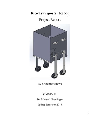
  • 1. 1 Rice Transporter Robot Project Report By Kristopher Brown CAD/CAM Dr. Michael Greminger Spring Semester 2015
  • 2. 2 Table of Contents Design Summary.........................................................................................3 Hopper .............................................................................................3 Motor plates......................................................................................3-4 Rack and Stilt Assembly....................................................................4 Rollers ..............................................................................................5 Bill of Materials ..........................................................................................6 Finite Element Analysis Setup.....................................................................7 Determining Volume and Load..........................................................7 Applying Loads and Constraints ........................................................7 Remote Load/Mass..................................................................7-8 Reaction Force........................................................................8 Finite Element Analysis Results ..................................................................9 Uniform Thickness............................................................................9 Multiple Thicknesses.........................................................................9-10 Confirming Finite Element Analysis...................................................11 Conclusion .................................................................................................12
  • 3. 3 Design Summary The main goal for the project was to maximize the carrying capacity of the hopper and minimize the material needed to structurally survive the required load with a displacement less than 0.5 mm. My design includes features that cater to both of these requirements while also considering the ease for assembly by the assembler. Hopper: The hopper is printed with multiple different thicknesses that optimize the displacement when under load. In order to reduce the unsymmetrical deformation the hopper experiences at max load, the thickness of the walls range from 2.28mm to 2.49 mm thick seen in figure 1. Figure 1: Top View of Hopper with Thicknesses Motor Plates: The upper and lower motor plates are of simple design. They are CNC threaded, and are machined from only one side which can be seen in figures 2 and 2.1. The blue circles on figure 2 represent where the plates fasten to the hopper and the red circles represent the threaded holes that are used to attach the motor to the plates. Figure 2 (left): Front View of Motor Plates Figure 2.1 (right): Top View of Motor Plates
  • 4. 4 The grooves machined into the plates allow for a snug fit with the motor. The design intends that the motor will be first fastened to the upper and lower plates before both plates are attached to the hopper. Rack and Stilt Assembly: Figure 3 (left): Front View of Rack and Stilt Figure 3.1 (center): Side View of Rack and Stilt Figure 3.2 (right): T-shape end attaching HUB-ee Wheels to Rack and Stilt The rack and stilt assembly are fastened together by two hex nuts represented by the green circles in figure 3. The stilt is threaded allowing for a tight assembly. To convert the rotational work done by the motor to linear motion of the rack and stilt, the motor pinion gear is tangent to the rack. The HUB-ee Wheels are fastened to the rack by pegs that are designed specifically for the ‘cross’ extrusion cut in the wheels. These pegs are made out of aluminum and will need to be CNC machined due to their groove radius of 0.5mm. Included in the hopper design are sliding brackets that support the upper and lower parts of the rack and stilt assemblies. They have clearances for the rack addendum and help resist rotational and bending deformations of the racks and stilts that may occur during loading. Figure 4: Top View of Bracket Figure 4.1: Isometric View of Upper Brackets
  • 5. 5 Figure 4.2: Front View of Lower Brackets Rollers: The transporter robot has rollers that help support its center of gravity when transitioning from the ground to the top of the 20 centimeter clearance. My design, which can be seen in figures 5 and 5.1, consists of a tri-sectioned roller design that is held and secured by 1.50 mm tabs. The reason I went with this tri-section design was because I wanted to have multiple support points in the middle as well as on ends of the hopper. Figure 5: Bottom View of Rollers Figure 5.1: Isometric View of Rollers and E-style ring
  • 6. 6 Bill Of Materials (BOM) Item # Part Name Manufacture Method Material Quanti ty 1 Hopper 3D Printed ABS 1 2 GW370 Motor Provided by Sumotor Zinc Alloy 2 3 Pinion Gear Provided by Manufacturer Aluminum 6 4 Teflon roller Provided by Manufacturer PTFE 12 5 Roller Shaft Provided by Manufacturer Steel 4 6 Reinforced E-style Retaining Ring SolidWorks Design Library Alloy Steel 8 8 Lower Motor Plate CNC (threaded) Aluminum 2 9 Upper Motor Plate CNC (threaded) Aluminum 2 10 B18.6.7M - M3 x 0.5 x 10 Indented HMS --10N SolidWorks Design Library SolidWorks Design Library 19 11 B18.6.7M - M3 x 0.5 x 13 Indented HMS --13S SolidWorks Design Library SolidWorks Design Library 17 12 B18.6.7M - M3 x 0.5 x 4 Indented HHMS --4N SolidWorks Design Library SolidWorks Design Library 8 13 B18.6.7M - M3 x 0.5 x 8 Indented HHMS --8N SolidWorks Design Library SolidWorks Design Library 16 14 Upper Sliding Bracket CNC (threaded) Plastic 8 15 Clamping Sliding Bracket CNC (threaded) Plastic 8 16 Pinion Shaft CNC Steel 2 17 B18.2.4.1M - Hex nut, Style 1, M3 x 0.5 --D-N SolidWorks Design Library SolidWorks Design Library 28 18 Rack Waterjet cut Plastic 4 19 Stilt Waterjet cut Aluminum 4 20 HUB-ee Wheels Provided by Manufacturer Provided by Manufacturer 4 21 HUB-ee Pegs CNC Aluminum 4 Table 1: Rice Transporter Robot Bill of Materials
  • 7. 7 Finite Element Analysis Setup Determining Volume and Load: After completing the assembly of the rice transporter robot, I isolated the hopper component to calculate the internal volume. This internal volume is the deciding factor on the rice carrying capacity of the hopper. To do this, I suppressed all the holes, and created a surface to cover the hopper. The hopper was then broken into two regions, creating default and volume configurations that can be found in the SolidWorks hopper part. Using the mass properties solver in SolidWorks, I found the initial volume before optimization to be 11,335,724.44 mm3. The density value used for dry rice (7.82x10⁻⁷ kg/m3) was obtained from aqua-calc.com. From these two values, I was able to find the weight by multiplying the mass of 8.8645 kg by gravity (9.81 m/s2). This calculation can be seen in figure 7 below. Figure 7: Calculating the Load Applying Loads and Constraints: I opened a static analysis in SolidWorks and began applying loads and constraints to the hopper. The total rice load of 86.961 N was applied uniformly to the bottom faces of the hopper, which can be seen in figure 7.1 below. All thickness trials were performed without the change of this load respective to the volume of the hopper, reducing the amount of iterations needed in order to optimize the design. Figure 7.1: Findingthe Load
  • 8. 8 Remote Load/Mass: To represent the force of each motor, a remote load was applied to the holes used for fastening the upper and lower motor plates to the hopper, see figure 8 and 8.1 below. In order to properly define this load, global coordinates were made at the contact point between the motor powered pinion gear and the rack. In my assembly, the y-axis is up, the z-axis is normal to the face of the hopper, and the x-axis is adjacent to the hopper. For one motor, all translation axes were set to zero. The opposing motor only had the x-and-y translations set to zero, because I wanted to restrict the rotation displacement without over constraining the analysis. Figure 8 (left): All three axes (x,y,z) translations set to zero Figure 8.1 (right): Two axes (y,z) translations set to zero Reaction Force: A ‘fixed geometry fixture’ constraint was placed on the two concentric shaft bearing holes that connect the motorized pinions to their opposing counterparts. This constraint simulates the reaction force of the connecting shaft acting on the hopper when load is applied. To do this, I applied a split line to the bearing holes shown in figure 9 below. Figure 9: Pinion Shaft Reaction Force Surface
  • 9. 9 Finite Element Analysis Results Uniform Thickness: Before performing the static analysis, I created a 7 mm fine curved base so the hopper could run properly. The first trial analyzed the initial uniform hopper thickness of 2mm and obtained a displacement result of 0.686 mm that can be seen in figure 10 and 10.1 below. Figure 10: 0.686 mm displacement Figure 10.1: 3.905 MPa Max annotation The max annotation stress shown in figure 10.2 is 3.905 MPa. The tensile strength of ABS is 13 MPa, which means that the factor of safety of my design is around 3.329. This is more than twice the design requirement of a 1.5 factor of safety. Multiple Thicknesses: With the displacement result of the uniform thickness trial being 0.186mm over the threshold of the 0.5 mm displacement design constraint, I decided to use the multiple thickness shell feature to reinforce specific sections of my hopper. I selected four faces. I set a thickness of 2.28mm for the top face, 2.41mm to the max displaced face, 2.4mm to the one adjacent to it, and 2.35 mm to the bottom face. Figures 11 and 11.1: Views of multi-thickness faces
  • 10. 10 The result from the multi-thickness hopper was a displacement of 0.5144 mm which can be seen from figure 12. This showed that the multi-thickness feature helped in reducing the displacement experienced by the whole hopper. Figure 12: Multiple Thickness Trial 1 With this data, I was able to better determine the increase of thicknesses needed to reinforce the hopper. I decided to increase the thicknesses as follows: top face maintained at 2.28 mm, the max displaced face from 2.41 to 2.49 mm, adjacent face from 2.4 to 2.46 mm, and maintained the bottom face at 2.40 mm. The change in thickness size resulted in a displacement of 0.4997 mm which is below the design threshold of 0.5 mm displacement seen in figure 13. The stress plot max annotation resulted in 3.425 MPa, which is a factor of safety of 3.796, more than twice the design requirement seen in figure 13.1. Figure 13: Displacement of 0.4997 mm Figure 13.1: 3.425 MPa stress max annotation This optimized design resulted in a volume of 11,238,169.27 cubic millimeters.
  • 11. 11 Confirming Finite Element Analysis: To confirm the reaction force on the pinion shaft holes, I performed a stress hand calculation that can be seen in figure 14. For the calculation, it was assumed that the reaction force of 63.7 N is distributed between the two holes, so 31.851 N was used for the force of one bearing hole. Figure 14: Stress at Shaft Hole Using the probe feature in the stress plot, I selected the split line plane for the hole and received a stress result of 2.344 MPa. This value is very similar to the hand calculation, solidifying the bearing holes were set up correctly. Figure 14.1: Reaction Stress To determine if the whole finite element analysis was correct, I confirmed the force applied by the remote load/mass of the motors and the upward reaction force from the pinion shaft bearing holes by adding them together. Their total equaled the initial load of 86.961 N which can be seen in figures 15 and 15.1 below. Figure 13 (left): Reaction Force Values Figure 15.1 (right): Remote Load/Mass Force
  • 12. 12 Conclusion: My final design resulted in a displacement of 0.4997 mm when under an 86.931 N load and holds 11,238,169.27 of dry rice. The design is simplistic, and easy to assemble. If I was able to lift some of the manufacturing constraints, I would design a hopper that was made up of multiple sections instead of one part. This way, I could create each section of the hopper using the current envelope size of 8x8x12 inches. It could potentially increase the carrying capacity by about four times the current volume. Also, if the 250 mm wide envelope design constraint would be waived, I would’ve not created the wheel wells. If I was able to work on the design further, I would create the brackets to push the stilts out a bit a more. When designing, I was cautious on how wide my final design would be. I ended up being 4.8 mm short of the 250 mm constraint. This was a missed opportunity in maximizing the volume. I would also make the brackets more supportive and robust in order to support the stilt/rack assemblies in this change. Along with this, I would increase the thickness of the motor plates to allow the motor to be fastened farther away from the hopper. This would reduce the displaced volume of the motor relative to the hopper. As far as the multi-thickness changes go, I did a lot of guess and check for this design. I would take more time or perform a design study next time to make sure that every thickness addition to the hopper was optimal.