Call Girls Electronic City Just Call 👗 7737669865 👗 Top Class Call Girl Servi...
General condition-relating-to-electricity new
1. General Conditions Relating To Supply
And Use Of Electrical Energy
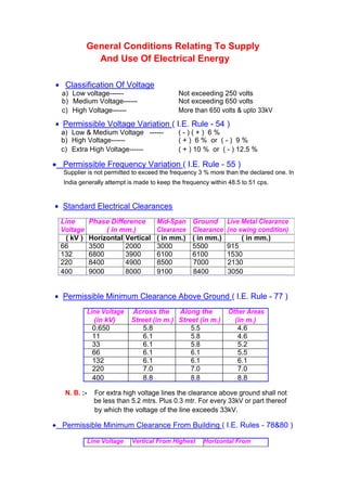
Classification Of Voltage
a) Low voltage------ Not exceeding 250 volts
b) Medium Voltage------ Not exceeding 650 volts
c) High Voltage------ More than 650 volts & upto 33kV
Permissible Voltage Variation ( I.E. Rule - 54 )
a) Low & Medium Voltage ------ ( - ) ( + ) 6 %
b) High Voltage------ ( + ) 6 % or ( - ) 9 %
c) Extra High Voltage------ ( + ) 10 % or ( - ) 12.5 %
Permissible Frequency Variation ( I.E. Rule - 55 )
Supplier is not permitted to exceed the frequency 3 % more than the declared one. In
India generally attempt is made to keep the frequency within 48.5 to 51 cps.
Standard Electrical Clearances
Line Phase Difference Mid-Span Ground Live Metal Clearance
Voltage ( in mm.) Clearance Clearance (no swing condition)
( kV ) Horizontal Vertical ( in mm.) ( in mm.) ( in mm.)
66 3500 2000 3000 5500 915
132 6800 3900 6100 6100 1530
220 8400 4900 8500 7000 2130
400 9000 8000 9100 8400 3050
Permissible Minimum Clearance Above Ground ( I.E. Rule - 77 )
Line Voltage Across the Along the Other Areas
(in kV) Street (in m.) Street (in m.) (in m.)
0.650 5.8 5.5 4.6
11 6.1 5.8 4.6
33 6.1 5.8 5.2
66 6.1 6.1 5.5
132 6.1 6.1 6.1
220 7.0 7.0 7.0
400 8.8 8.8 8.8
N. B. :- For extra high voltage lines the clearance above ground shall not
be less than 5.2 mtrs. Plus 0.3 mtr. For every 33kV or part thereof
by which the voltage of the line exceeds 33kV.
Permissible Minimum Clearance From Building ( I.E. Rules - 78&80 )
Line Voltage Vertical From Highest Horizontal From
2. (in kV) Object (in m.) Nearest Point
(in m.)
0.650 2.5 1.2
11 3.7 1.2
33 3.7 2.0
66 4.0 2.3
132 4.6 2.9
220 5.5 3.8
400 7.3 5.6
Clearance Of Overhead Lines Crossing Each Other ( I.E. Rule - 87 )
Line 11kV 33kV 66kV 132kV 220kV 400kV
Voltage (in m.) (in m.) (in m.) (in m.) (in m.) (in m.)
(in kV)
0.250 2.44 2.44 2.44 3.05 4.58 6.00
0.650 2.44 2.44 2.44 3.05 4.58 6.00
11 2.44 2.44 2.44 3.05 4.58 6.00
33 2.44 2.44 2.44 3.05 4.58 6.00
66 2.44 2.44 2.44 3.05 4.58 6.00
132 3.05 3.05 3.05 3.05 4.58 6.00
220 4.58 4.58 4.58 4.58 4.58 6.00
400 6.00 6.00 6.00 6.00 6.00 6.00
N. B. :- # Suitable guarding arrangement should be provided to guard against
possibility of coming in contact with each other.
# No guarding is required when an extra high voltage line crosses
over another extra high voltage / high voltage / medium voltage line.
# Crossing shall be made as nearly at right angles, as near the
support of the upper line. Support of the lower line shall not be
erected below the upper line.
Railway Crossing Clearances
Line Voltage Broad Gauge & Narrow Gauge
( in mtrs. )
Up to and including 11kV Normally by Cable
Above 11kV and up to 66kV 14.10
Above 66kV and up to 132kV 14.60
Above 132kV and up to 220kV 15.40
Above 220kV and up to 400kV 17.90
En-route Tree Clearance From Over Head Lines
Line On Either Side Of The Line
( in mtrs. )
Extra High Voltage Line 12.19
High Voltage Line 6.095
3. Low & Medium Voltage Line 0.914
Clearance Over The River
Clearance must be minimum of 3.048 metres over highest flood level ( in
case of non-navigable river ). In case of navigable river clearance must be
decided in relation to the tallest mast of the ship passing through the river.
Clearance Between Power And Communication Lines
a) Low and medium voltage line ----- 1380 mm ( 4’6” )
b) H.V. lines up to & including 7.2 kV ----- 1525 mm ( 5’0” )
c) H.V. lines up to 12 kV ----- 2130 mm ( 7’0” )
Clearance between communication and ground wires will not be less
than 1070 mm ( 3’6” ). The minimum clearance between the guard wires and
telecommunication lines shall be 600 mm. If the guards are fastened to the
same supports as the power line, then the minimum distance will be 900 mm.
Line Clearance In WBSEB System
Line Voltage Ph - Ph Ph - E Ground Clearance
( kV ) (mts.) (mts.) (mts.)
Single Double Single Double Single Double
Circuit Circuit Circuit Circuit Circuit Circuit
400 11 8 9.26 9.30 8.84 8.84
220 7.55 7.8 4.9 4.9 7.015 7.015
132 5.37 5.63 4.0 4.0 6.10 6.10
66 4.8 3.44 5.49
Total Number Of Disc Insulators In A String
Line Voltage ( kV ) Suspension String Tension String
66 5 6
132 9 10
220 14 15
400 22 23
Switchyard Parameters
Phase Clearance (Outdoor) Bus
Bus Voltage (kV) Ph - Ph (mts.) Ph - E (mts.) Bay Width (mts.)
33 1.3 1.9 6.1
4.
5. 66 1.7 2.2 7.7
132 2.8 3.4 12.2
220 4.5 4 17
400 7 6.5 27
Bus Height
Bus Voltage (kV) Low Bus (mts.) Main Bus (mts.) Jack Bus (mts.)
132 5.5 8.42 12.85
220 6.25 10.95 16.5
400 8.2 15.5 23
Earthing Resistance (Ideal Value)
Generating Station and Big Sub-Station : 0.5
132 kV Sub-Station : 1
66 kV Sub-Station : 2 - 4
33 kV Sub-Station : 4 - 6
Current Carrying Capacity Of Underground Cable
Conductor 6.6 & 11 kV 6.6 & 11 kV insulated 6.6 & 11 kV XLPE
Size P.I.L.C. armoured, armoured, screen Cable Aluminium
(sq. mm) served belted, 3 sheathed, Aluminium Conductor
core Aluminium Conductor (Amps) (Amps)
Conductor (Amps)
Single Core Three Core Single Core Three Core
In In Air In In In In In In In In
Ground Grou Air Grou Air Grou Air Grou Air
nd nd nd nd
16 58 50 - - - - - - - -
7. Important Data Of All Aluminium Conductor ( A.A.C. )
Code Ward Strand Size Cu. Eq. Nominal Nominal Max. Current Resistance at Approx. ultimate Approx. Weight
(mm.) SWG Copper Area Aluminium Carrying 20
0
C Tensile Strength (Kg/KM)
No. (sq. mm) Area Capacity At (Ohms/KM) (Kg)
(sq. mm) 40
0
C Ambient
(Amp.)
Canops 7 / 1.96 8 13 20 105 1.362 385 58
Gnat 7 / 2.21 7 16 25 125 1.071 485 73
Weevil 7 / 2.44 6 20 30 145 0.879 580 89
Ant 7 / 3.10 3 30 50 200 0.544 892 144
Important Data Of Aluminium Conductor Steel Reinforced ( A.C.S.R. )
Code Ward Nominal Calculated No. Of Dia. Of Overall Max. Current Resistance at Approx. Approx.
Copper Eq. Area Of Wires Wires Dia Of Carrying 20
0
C ultimate Weight
Area (sq. Aluminium (mm) Conducto Capacity At (Ohms/KM) Tensile (Kg/KM)
mm (sq. mm) r (mm) 40
0
C Ambient Strength
Al. St. Al. St. (Amp.) (Kg)
Squirrel 13 20.71 6 1 2.11 2.11 6.33 115 1.374 771 85
Weasel 20 31.21 6 1 2.59 2.59 7.77 150 0.9116 1136 128
Rabbit 30 52.21 6 1 3.35 3.35 10.05 200 0.5449 1860 214
Raccoon 48 77.83 6 1 4.09 4.09 12.27 270 0.3656 2746 318
Dog 65 103.6 6 7 4.72 1.57 14.15 324 0.2745 3299 394
Panther 130 207.0 30 7 3.00 3.00 21.00 520 0.1375 9127 976
Deer 260 419.3 30 7 4.27 4.27 29.89 806 0.06786 18230 1977
Zebra 260 418.6 54 7 3.18 3.18 28.62 795 0.0680 13316 1623
Moose 325 515.7 54 7 3.53 3.53 31.77 900 0.05517 16250 2002
8. Recommended Size Of Fuses
Fuses are overcurrent devices and must have ratings well above the maximum
transformer load current in order to carry without ‘blowing’ during the short duration
overloads that may occur because of motor starting. Also the fuses must able to withstand
the magnetising inrush current drawn when the power transformers are energised.
POWER TRANSFORMER
Sl. Transformer Voltage High Voltage Side Low Voltage Side
No. Capacity Ratio (33 kV) (11 0r 6.6 kV)
(MVA) (kV) Full load Size of Full load Size of
current fuse wire current fuse wire
(amps.) (SWG) (amps.) (SWG)
1. 0.50 33/6.6 8.75 28 48 18
2. 1.00 33/6.6 17.5 23 96 14
3. 3.00 33/6.6 52.5 17 288.7 OCB
4. 0.50 33/11 8.75 28 26.3 21
5. 0.63 33/11 11.0 24 33.0 21
6. 1.00 33/11 17.5 23 52.5 15
7. 1.60 33/11 28.0 21 84.0 14
8. 3.15 33/11 55.0 17 165.3 2 X 14
9. 5.00 33/11 87.5 OCB 262.4 OCB
10. 6.30 33/11 110.2 OCB 330.6 OCB
DISTRIBUTION TRANSFORMER
Sl. Transformer Voltage High Voltage Side Low Voltage Side
No. Capacity Ratio (11 0r 6.6 kV)
(MVA) (kV) Full load Size of Full load Size of
current fuse wire current fuse wire
(amps.) (SWG) (amps.) (SWG)
1. 25 6.6/0.4 2.4 38 36 22
2. 63 6.6/0.4 6.0 35 91 17
3. 100 6.6/0.4 9.6 28 149 12
4. 25 11/0.433 1.31 39 33.3 22
5. 63 11/0.433 3.30 38 84.0 17
6. 100 11/0.433 5.25 35 133.3 1 X 14
7. 200 11/0.433 10.5 28 266.6 HRC 250
8. 250 11/0.433 13.12 25 333.3 HRC 320
Construction Of Transmission And Distribution Lines
9. Transmission means conveyance of electrical power at Extra High Voltage
from the generating stations to the grid Sub-stations or between Grid Sub-Stations.
Distribution is the term used for conveyance of electrical power from the Sub-
stations to the actual consumers at high or medium or low voltage.
Transmission & distribution of power can be done with the help of -
i) Overhead lines
ii) Underground cables.
Type Of Power Advantages Disadvantages
Transmission
Overhead lines Cheaper Prone to disturbances from
Easy to maintain weather, lightning strokes
etc.
Underground cables Easy for power Takes longer time for
distribution in congested
breakdown repair.
urban areas, factories, Costlier
residences, power houses,
Sub-stations etc.
1. The main items in an over head line are :
a) Conductor, b) Supports, c) Insulators, d) Metal Hardware
a) Conductor
The principal materials used as conductors in construction of overhead lines are -
i) Hard drawn copper,
ii) All Aluminium Conductor (AAC)
iii) Aluminium Conductor Steel Reinforced (ACSR)
iv) Cadmium Copper
i) Steel
v) All Aluminium Alloy Conductor (AAAC)
i) Aluminium Conductor Alloy Reinforced (ACAR)
vi) Aluminium Alloy Conductor Steel Reinforced (AACSR)
b) Supports
i) Wood poles
ii) Steel Tubular poles
iii) Rails and R.S. Joists
iv) Lattice type poles
v) Steel Towers
vi) Reinforced cement concrete poles (RCC)
vii) Pre-stressed cement concrete poles (PCC)
c) Insulators
i) Pin insulators
ii) Shackle insulators
iii) Disc insulators
iv) Strain insulators
10. i) Post insulators
d) Metal Hardware
i) Strain clamp
ii) Suspension clamp
iii) Twisting joint sleeve
iv) Repair sleeve
v) Bolted clip
vi) Tubular compression joint
vii) Parallel Groove clamp (P.G.)
viii) Vibration damper
2. Other Factors For Line Construction
i) Bracket or cross arm
ii) Earthing system
iii) Stay and struts
iv) Foundation
v) Jointing
vi) Armoring
vii) Dumper
viii) Guard and safety device
ix) Anti climbing device
x) Danger notice
xi) Pole numbering
Functions Of Transmission (O&M) Sub-Division
1. Attending breakdown of lines and Sub-Stations.
2. Preventive maintenance work
i) Winter maintenance program.
11. ii) Pre-puja maintenance work.
iii) Pre-norwester maintenance work.
3. Procurement of spare equipment and equipment’s spares for both
breakdown replacement and preventive maintenance work.
4. Up-keepment of control room building switchyard by periodical
maintenance through annual maintenance program.
5. Ensuring round the clock vigilance for maintenance of power system.
a) Through the duty roaster of operational staff, arrangement of
necessary availability of maintenance staff, vehicle for attending
breakdown jobs at the shortest possible time.
b) Maintaining proper communication system with other Sub-station from which
power is drawn and other distribution Sub-Stations and bulk consumer
through which power is distributed.
6. Means of communication :
i) P & T telephone
ii) VHF communication
iii) PLCC ( power line carrier communication )
iv) Future communication - VSAT communication
i) Maintaining walkie-talkie sets for small distance communication.
v) Allotment of staff quarters for emergency maintenance & operational staff.
7. Operation of the Sub-station :
Switching instruction are displayed in all Sub-stations for switching
operation of different equipment during faulty condition or shutdown
operation or interchanging of source of supply, shedding of power in case
of scarcity in availability as directed by Central Load Despatch and also to
save the system from total disaster.
Functions Of Transmission Construction Sub-Division
Construction Of Sub-Station :-
1. Selection of site and acquisition process of the land through land acquisition
department, Govt. of West Bengal with the assistance of the land acquisition cell
of WBSEB, after issuance of work order by the CP & ED wing.
2. Soil testing work to facilitate CP & ED wing to prepare the design of foundation of
structures and equipment and also control room building, staff quarters etc.
3. Preparation of estimate for boundary wall, foundation of equipment and
structures, control room building on the basis of soil testing report for tender call.
4. Preparation of estimate for erection of structures and equipment as per lay out
drawing submitted by CP & ED wing.
12. 5. Preparation of list of materials and equipment like - isolators, C.Ts., L.As., OCBs
etc. are to be prepared and requisition of materials are to be placed to CP & ED
wing through proper channel for procurement action.
6. Estimate for -
a) earthmat arrangement for earthing of equipment.
b) cable trenches are also to be prepared as per layout drawing.
c) similar estimate for land filling work, surface drain work, construction of store
shed, staff quarters, children park, recreation room etc. should also be
prepared for inviting tenders for construction work.
7. List of equipment to be installed for inside the control room like control pannel,
battery charger pannels and control cable for connecting equipment in the switchyard
with the control pannel should also be prepared for procurement action by the CP &
ED / Central purchase wing.
Construction Of Over head Transmission Line:-
1. By preliminary route survey, alternative routes or alignment are to be prepared
avoiding congested areas, railway crossings, roads, rivers, as far as practicable.
2. Gazette notification & newspaper publication will be necessary mentioning the
names of Mouzas through which the line will pass for general information of
public in terms of section 29 & 42 of I.E. Act, 1948.
3. Soil resistivity test is to be conducted along the route alignment and after that,
schedule of towers involving the angle at different points are to be prepared.
i) ‘A’ type tangent tower tolerable angle up to 2
0
ii) ‘B’ type tower tolerable angle 2
0
to 30
0
iii) ‘C’ type tower tolerable angle 30
0
to 60
0
iv) ‘D’ type tower above 60
0
and dead-end tower.
The foundation of the towers are designed according to the condition of the soil
over which the route alignment is drawn -
i) dry soil
ii) semi-submerged soil
iii) fully submerged soil.
4. After getting the preliminary survey report, specification for supply of different
kind of towers and required foundation are to be prepared for tendering purpose.
5. Permission for Rly. Crossing & forest deptt. & clearance for environment deptt. &
Airport Authority, National High way Authority are to be taken.
TRANSFORMER PROTECTION
Protection Is Provided To Minimise -
a) Cost of repair of damage.
b) Possibility of spreading & involving other equipment.
c) Timely out of service of the equipment.
d) Loss in revenue and of course the strained public relations.
Protection System Should Be -
13. a) Very fast - Operate with correct speed i.e. fast clearance of fault to minimise damage
and increase power system stability.
b) Selective - Able to discriminate between faulty & healthy equipment.
c) Sensitive - Can operate under minimum generating condition and
d) Stable - Stabilise under external fault condition and should not result in
undesired tripping when there is no fault in the equipment protected.
TRANSFORMER IS VIRTUALLY AN IMPEDANCE CONNECTED TO THE SYSTEM.
Faults In Transformer
Sl. Fault Causes Effect Occurrence
No.
1. Phase Fault Mostly ground faults in High current, Rare
(Phase to 2 phases, flashover, Mechanical Stress.
Phase) insulation failures.
2. Ground Fault Insulation failure. High current in grounded Common
neutral operation.
3. Inter Turn Insulation failure. Short circuit current is Common
Fault high but line terminal
current is low.
4. Inter Winding Insulation failure Over voltage leading to Rare
Fault between windings - developing ground fault.
primary to secondary.
5. Core Fault Laminations getting Eddy current heating Common
bridged, core bolt
increases,
insulation failure. Increase of noise.
6. Radiator Choking of pipes by Abnormal heating, Common
Fault, sludge in oil, cooling Winding damage,
Cooling duct ducts also may be Oil break down and gas
Fault affected. formation.
In our system transformer ratings up to 3 MVA are generally protected only by fuse.
Fuses are over-current devices and must have ratings well above the maximum
transformer load current in order to carry, without blowing, the short duration over loads
that may occur because of such as motor starting, also the fuses must withstand the
magnetising inrush current drawn when power transformers are energised.
The protection provided for large capacity transformers are described hereunder –
1) Temperature Relay :
The temperature indicator is fitted with mercury switches fixed on the pointer, so that
on temperature rise, the switch tilts and makes contact through mercury between two
electrodes which are connected to electric to initiate proper action. Detection of over-
heating is normally done by –
a) Oil Temperature Indicator (OTI)
b) Winding Temperature Indicator (WTI) – The winding temperature is indirectly
obtained by measuring the top oil temperature by a Bourdon liquid expansion
indicator mounted in a pocket, which also contains a heater element energised
from a phase CT. The thermometer thus measures top oil temperature plus an
increment proportional to load current.
14. Settings of WTI & OTI in WBSEB for several actions –
Protection System Cooling System
Alarm Trip Fan ON Fan OFF Pump ON Pump OFF
O.T.I. 80
o
C 90
o
C - - - -
W.T.I. 90
o
C 95
o
C 65
o
C 55
o
C 70
o
C 60
o
C
2) Oil and Gas Devices :
a) Boucholz Relay / Protective Surge Relay – When a transformer is fitted with conservator,
the formed gas within the transformer, flows towards the conservator where atmospheric
pressure exists. Boucholz Relay is mounted in the pipe which has a slope between main
tank and conservator. If the fault is of very minor nature, gases are liberated slowly and
stream of gas bubbles flow towards conservator. But if there is violent evolution of gas, a
sudden surge of oil flow towards the conservator followed by the gaseous products.
Bucholz relay has two floats with mercury switches attached –
i) The upper float (for alarm) moves down when gas slowly accumulates on the
upper part of the chamber (result of incipient fault, failure of lamination insulation /
core bolt insulation / interturn fault).
ii) A surge of oil however deflects the lower float (for trip) and closes mercury switch
(indicating heavy fault / short circuits). In this case gas may not accumulate in relay.
For a loss of oil condition also, both the floats make contacts of the corresponding
mercury switch (low oil level condition).
I.S.S. (Indian Standard Specification) 3637 – 1966 sets down the following figures
relating to a Bucholz relay –
Nominal Pipe Bore (mm.) Gas volume for alarm at 5 Steady oil flow for trip at
o
pipe angle (cc) 1-9
o
pipe angle (cm/sec)
25 90 – 165 70 – 130
50 175 – 225 75 – 140
80 200 – 300 90 – 160
N.B. – 1. Often after initial energisation of transformer, the trapped air get released
by vibration & warming up of the oil and operate the Bucholz Relay. To prevent this
proper release of air from bushing turrets, radiators, tank-tops are required.
2. Oil surges also occur when the transformer feeds external short circuits and
there is dynamic stress in the windings. Thus if Bucholz Relay is made very
sensitive, there is chance of operation for fault outside the transformer.
Type of Relay -
Relay No. Name Of The Relay
2 Time delay relay
3 Checking or interlocking relay
21 Distance protection relay
25 Synchronising / Syn. Check relay
27 Under voltage check relay
15. 30 Annunciation relay
32 Directional power relay
37 Under current or under power relay
40 Field failure relay
46 Reverse phase or phase balance current relay
49 Machine or transformer thermal relay
50 Instantaneous over-current relay
50 N Instantaneous earth-fault relay
51 IDMT (Inverse Definite Minimum Time) O/C relay
51 N IDMT (Inverse Definite Minimum Time) E/F relay
52 Circuit Breaker
52 a Circuit Breaker auxiliary contact N/O
52 b Circuit Breaker auxiliary contact N/C
55 Power factor relay
56 Field application relay
59 Over voltage relay
60 V / I balance relay
64 REF (Restricted Earth Fault) Relay
67 Directional O/C & E/F relay
68 Blocking relay
74 Supervision relay
79 AC reclosing relay
80 DC fail relay
86 Lock out / Trip
87 Differential relay
Protective Relays
Over Current Relay
Excessive current flow through an electrical circuit due to a fault in any part of the
network or due to abnormal operating condition in the system, is most conveniently
detected by overcurrent relays which operate when the magnitude of current through
it exceeds a set value. These are again of the following types -
16. i) Instantaneous - time a few cycles only
ii) Definite time - fixed intentional time delay independent of current magnitude
iii) Inverse time - operating time decreases as actuating current increases.
According to the characteristics, these are classified as
- a) Inverse, b) Very Inverse, c) Extremely Inverse.
The most commonly used type of relays work on induction (electromagnetic)
principle and develop torque proportional to I
2
. Hence the torque increases rapidly
with current, but beyond a certain value of current depending on the core
construction, saturation sets-in and the induction decreases so that further increase
of current does not increase the torque and the relay operating time levels out to a
definite time. Such characteristic is known as Inverse Definite Minimum Time (IDMT).
Fault Calculation
For determining the settings of relays a knowledge of the fault current that can
flow through the network into the fault is necessary. Hence the data required for the
setting study are :
a) Single line diagram of the system with ratings and impedance of Generators,
Transformers, Feeders with details of CTs and protective relays shown.
b) Maximum and minimum of short circuit current expected to flow through each
protective device.
c) Characteristic curve of relays.
d) Maximum peak load current through the protective device including starting
current of motors, if supplied.
The basic principle followed in relay settings is to allow shortest operating time for
maximum fault current and then recheck the time co-ordination at minimum fault current.
For the calculation of the fault current, the data of %IZ or the line impedance in ohms
must refer to a common base MVA and base voltage level. With the above the network may
be reduced to a single source with series impedance for ease in fault current calculation.
Base MVA is the 3-phase power
Base voltage is line voltage in kV
We know, MVA = 1000 . kV . I = 1000 . kV . ( V / Z )
= 1000 . kV . { ( kV / 1000 ) / Z } = ( kV )
2
/ Z
So, Base Impedance = ( kV )
2
/ MVA
Per unit impedance = (Actual Impedance) / (Base Impedance)
= Z / {( kV )
2
/ MVA } = Z . (Base MVA) / (Base kV )
2
Z p.u. (new base MVA) = Z p.u. (given base MVA) X [(new base MVA) / (given base MVA)]
Z p.u. (new base kV) = Z p.u. (given base kV) X [(new base kV) / (given base kV)]
2
Example :
10 Miles 5 Miles
132 kV 0.6 / m 0.6 / m
Source
17.
18. 33 / 11 kV
A B C 10 MVA, 7% % D
132 / 33 kV
50 MVA, 10%
The h.v. source is assumed to have negligible source impedance. Converting all the
impedance to a common base MVA of say 100 MVA,
Tr. at D, % impedance on 100 MVA = 7 x (100 / 10) = 70 % = 0.7 p.u.
Line BC, % impedance = (5 x 0.6 x 100) / 33
2
= 0.2754 p.u.
Line AB, % impedance= (10 x 0.6 x 100) / 33
2
= 0.55 p.u.
50 MVA Tr., % impedance on 100 MVA = 10 x (100 / 50) = 20 % = 0.2 p.u.
2 x 50 MVA Tr. in parallel, % impedance on 100 MVA = 10 % = 0.1 p.u
Fault Levels
At Bus D = 100 / (0.7 + 0.2754 + 0.55 + 0.1) = 61.35 MVA
At Bus C = 100 / (0.2754 + 0.55 + 0.1) = 107.53 MVA
At Bus B = 100 / (0.55 + 0.1) = 153.85 MVA
At Bus A, Maximum = 100 / 0.1 = 1000 MVA
Minimum = 100 / 0.2 = 500 MVA
Considering only one 50 MVA Tr. in service, the minimum fault levels are -
At Bus D = 57.9 MVA
At Bus B = 97.5 MVA
At Bus C = 133.3 MVA
At Bus A = 500 MVA
Location Fault MVA Fault Current, Amps.
Maximum Minimum Maximum Minimum
A 1000 500 17540 8770
B 154 133.3 2700 2340
C 108 97.5 1900 1710
D 61.5 57.9 1080 1010
Alternative Method :
The same calculation of fault current could as well be done from ohmic values of the
impedance in the circuit.
Z in ohm = Z p.u. x kV
2
/ MVA
2.18 For 50 MVA Tr. at 33 kV, Z = 0.1 x 33
2
/ 50 =
For the transformers in parrel at 33 kV side, Z s = 1.09
Line AB, ZAB = 6
Line BC, ZBC = 3
7.623 For 10 MVA Tr. at 33 kV, Z T = .07 x 33
2
/ 10 =
Fault at A at 33 kV side, I FA = (33 / 3) / 1.09 = 17480 amps.
Fault at B, I FB = (33 / 3) / (6 + 1.09) = 2687 amps.
Fault at C, I FC = (33 / 3) / (3 + 6 + 1.09) = 1888 amps.
Fault at D at 33 kV side, I FD = (33 / 3) / (7.623 + 3 + 6 + 1.09) = 1075 amps.
at 11 kV side, I FD = (11 / 3) / (7.623 + 3 + 6 + 1.09) = 3225 amps.
Selection Of CT Ratios :
The CT ratios for each section of the feeders are selected from the data of maximum
load current flowing into the section. The settings of the protective relays should be safely