SlideShare ist ein Scribd-Unternehmen logo
1 von 155
Downloaden Sie, um offline zu lesen
TRAINING MATERIAL
Heat Exchangers:
Design, Operation, Maintenance and Enhancement
2 Table of contents
Table of contents
1 Introduction 8
1.1 Programm outline . . . . . . . . . . . . . . . . . . . . . . . . . . . . . . . . 8
1.2 Instructor . . . . . . . . . . . . . . . . . . . . . . . . . . . . . . . . . . . . 10
2 Classification of heat exchangers 12
2.1 Classification by construction . . . . . . . . . . . . . . . . . . . . . . . . . 14
2.1.1 Tubular heat exchanger . . . . . . . . . . . . . . . . . . . . . . . . 14
2.2 Double pipe heat exchanger . . . . . . . . . . . . . . . . . . . . . . . . . . 15
2.3 Spiral tube heat exchanger . . . . . . . . . . . . . . . . . . . . . . . . . . . 16
2.4 Shell and tube heat exchanger . . . . . . . . . . . . . . . . . . . . . . . . . 16
2.4.1 Fixed tubesheet . . . . . . . . . . . . . . . . . . . . . . . . . . . . . 17
2.4.2 U-tube . . . . . . . . . . . . . . . . . . . . . . . . . . . . . . . . . 17
2.4.3 Floating head . . . . . . . . . . . . . . . . . . . . . . . . . . . . . . 18
2.5 Plate heat exchangers . . . . . . . . . . . . . . . . . . . . . . . . . . . . . 19
2.5.1 Gasketed plate heat exchanger . . . . . . . . . . . . . . . . . . . . 20
2.5.2 Welded- and Brazed-Plate exchanger (W. PHE and BHE) . . . . . 22
2.5.3 Spiral Plate Exchanger (SPHE) . . . . . . . . . . . . . . . . . . . . 23
2.6 Extended surface . . . . . . . . . . . . . . . . . . . . . . . . . . . . . . . . 26
2.6.1 Plate fin . . . . . . . . . . . . . . . . . . . . . . . . . . . . . . . . . 26
2.6.2 Tube fin . . . . . . . . . . . . . . . . . . . . . . . . . . . . . . . . . 27
3 Code and standards 28
3.1 TEMA Designations . . . . . . . . . . . . . . . . . . . . . . . . . . . . . . 28
3.2 Classification by construction STHE . . . . . . . . . . . . . . . . . . . . . 33
3.2.1 Fixed tube sheet . . . . . . . . . . . . . . . . . . . . . . . . . . . . 33
3.2.2 U-Tube Heat Exchanger . . . . . . . . . . . . . . . . . . . . . . . . 35
3.2.3 Floating Head Designs . . . . . . . . . . . . . . . . . . . . . . . . . 37
3.3 Shell Constructions . . . . . . . . . . . . . . . . . . . . . . . . . . . . . . . 41
3.4 Tube side construction . . . . . . . . . . . . . . . . . . . . . . . . . . . . . 42
3.4.1 Tube-Side Header: . . . . . . . . . . . . . . . . . . . . . . . . . . . 42
3.4.2 Tube-Side Passes . . . . . . . . . . . . . . . . . . . . . . . . . . . . 42
3.4.3 Tubes Type . . . . . . . . . . . . . . . . . . . . . . . . . . . . . . . 43
3.4.4 Tube arrangement . . . . . . . . . . . . . . . . . . . . . . . . . . . 46
3.4.5 Tube side passes . . . . . . . . . . . . . . . . . . . . . . . . . . . . 47
3.5 Shell side construction . . . . . . . . . . . . . . . . . . . . . . . . . . . . . 47
3.5.1 Shell Sizes . . . . . . . . . . . . . . . . . . . . . . . . . . . . . . . . 47
3.5.2 Shell-Side Arrangements . . . . . . . . . . . . . . . . . . . . . . . . 48
3.6 Baffles and tube bundles . . . . . . . . . . . . . . . . . . . . . . . . . . . . 48
3.6.1 The tube bundle . . . . . . . . . . . . . . . . . . . . . . . . . . . . 48
Dr. Ali A. Rabah, Dept of Chemeng, U of K, Email : rabahss@hotamil.com
Table of contents 3
3.6.2 Baffle . . . . . . . . . . . . . . . . . . . . . . . . . . . . . . . . . . 48
3.6.3 Vapor Distribution . . . . . . . . . . . . . . . . . . . . . . . . . . . 51
3.6.4 Tube-Bundle Bypassing . . . . . . . . . . . . . . . . . . . . . . . . 51
3.6.5 Tie Rods and Spacers . . . . . . . . . . . . . . . . . . . . . . . . . . 52
3.6.6 Tubesheets . . . . . . . . . . . . . . . . . . . . . . . . . . . . . . . 52
4 Basic Design Equations of Heat Exchangers 55
4.1 LMTD-Method . . . . . . . . . . . . . . . . . . . . . . . . . . . . . . . . . 55
4.1.1 Logarithmic mean temperature different . . . . . . . . . . . . . . . 56
4.1.2 Correction Factor . . . . . . . . . . . . . . . . . . . . . . . . . . . . 57
4.1.3 Overall heat transfer coefficient . . . . . . . . . . . . . . . . . . . . 59
4.1.4 Heat transfer coefficient . . . . . . . . . . . . . . . . . . . . . . . . 61
4.1.5 Fouling factor (hid, hod) . . . . . . . . . . . . . . . . . . . . . . . . . 61
4.2 ε- NTU . . . . . . . . . . . . . . . . . . . . . . . . . . . . . . . . . . . . . 61
4.3 Link between LMTD and NTU . . . . . . . . . . . . . . . . . . . . . . . . 64
4.4 The Theta Method . . . . . . . . . . . . . . . . . . . . . . . . . . . . . . . 64
5 Thermal Design 66
5.1 Design Consideration . . . . . . . . . . . . . . . . . . . . . . . . . . . . . . 66
5.1.1 Fluid Stream Allocations . . . . . . . . . . . . . . . . . . . . . . . . 66
5.1.2 Shell and tube velocity . . . . . . . . . . . . . . . . . . . . . . . . . 66
5.1.3 Stream temperature . . . . . . . . . . . . . . . . . . . . . . . . . . 67
5.1.4 Pressure drop . . . . . . . . . . . . . . . . . . . . . . . . . . . . . . 67
5.1.5 Fluid physical properties . . . . . . . . . . . . . . . . . . . . . . . . 67
5.2 Design data . . . . . . . . . . . . . . . . . . . . . . . . . . . . . . . . . . . 68
5.3 Tubeside design . . . . . . . . . . . . . . . . . . . . . . . . . . . . . . . . . 69
5.3.1 Heat-transfer coefficient . . . . . . . . . . . . . . . . . . . . . . . . 69
5.3.2 Pressure drop . . . . . . . . . . . . . . . . . . . . . . . . . . . . . . 70
5.4 Shell side design . . . . . . . . . . . . . . . . . . . . . . . . . . . . . . . . . 72
5.4.1 Shell configuration . . . . . . . . . . . . . . . . . . . . . . . . . . . 72
5.4.2 Tube layout patterns . . . . . . . . . . . . . . . . . . . . . . . . . . 73
5.4.3 Tube pitch . . . . . . . . . . . . . . . . . . . . . . . . . . . . . . . . 73
5.4.4 Baffling . . . . . . . . . . . . . . . . . . . . . . . . . . . . . . . . . 74
5.4.5 Equalize cross-flow and window velocities . . . . . . . . . . . . . . . 76
5.4.6 Shellside stream analysis (Flow pattern) . . . . . . . . . . . . . . . 76
5.4.7 Heat transfer coefficient and pressure drop . . . . . . . . . . . . . . 77
5.4.8 Heat transfer coefficient . . . . . . . . . . . . . . . . . . . . . . . . 78
5.4.9 Pressure drop . . . . . . . . . . . . . . . . . . . . . . . . . . . . . . 78
5.5 Design Algorithm . . . . . . . . . . . . . . . . . . . . . . . . . . . . . . . . 79
6 Specification sheet 80
Dr. Ali A. Rabah, Dept of Chemeng, U of K, Email : rabahss@hotamil.com
4 Table of contents
6.1 Information included . . . . . . . . . . . . . . . . . . . . . . . . . . . . . . 80
6.2 Information not included . . . . . . . . . . . . . . . . . . . . . . . . . . . . 80
6.3 Operation conditions . . . . . . . . . . . . . . . . . . . . . . . . . . . . . . 80
6.4 Bid evaluation . . . . . . . . . . . . . . . . . . . . . . . . . . . . . . . . . . 81
6.4.1 Factor to be consider . . . . . . . . . . . . . . . . . . . . . . . . . . 81
7 Storage, Installation, Operation and Maintenance 83
7.1 Storage . . . . . . . . . . . . . . . . . . . . . . . . . . . . . . . . . . . . . . 83
7.2 Installation . . . . . . . . . . . . . . . . . . . . . . . . . . . . . . . . . . . 85
7.2.1 Installation Planning . . . . . . . . . . . . . . . . . . . . . . . . . . 85
7.2.2 Installation at Jobsite . . . . . . . . . . . . . . . . . . . . . . . . . 86
7.3 Operation . . . . . . . . . . . . . . . . . . . . . . . . . . . . . . . . . . . . 87
8 Heat exchanger tube side mainenance (Repair vs replacement 91
8.1 Introduction . . . . . . . . . . . . . . . . . . . . . . . . . . . . . . . . . . . 91
8.2 Repair vs. Replace - Factors To Consider . . . . . . . . . . . . . . . . . . . 92
8.3 Heat Exchanger maintenance Options . . . . . . . . . . . . . . . . . . . . . 93
8.4 Repair option . . . . . . . . . . . . . . . . . . . . . . . . . . . . . . . . . . 94
8.4.1 Plug . . . . . . . . . . . . . . . . . . . . . . . . . . . . . . . . . . . 94
8.4.2 Sleeving . . . . . . . . . . . . . . . . . . . . . . . . . . . . . . . . . 95
8.4.3 Tube Expansion . . . . . . . . . . . . . . . . . . . . . . . . . . . . . 100
8.5 Replacement option . . . . . . . . . . . . . . . . . . . . . . . . . . . . . . . 103
8.5.1 Retubing . . . . . . . . . . . . . . . . . . . . . . . . . . . . . . . . . 103
8.5.2 Rebundling . . . . . . . . . . . . . . . . . . . . . . . . . . . . . . . 104
8.5.3 Complete replacement (New unit) . . . . . . . . . . . . . . . . . . . 104
8.6 Conclusions . . . . . . . . . . . . . . . . . . . . . . . . . . . . . . . . . . . 105
9 Troubleshooting 106
9.1 Heat exchangers’ problems . . . . . . . . . . . . . . . . . . . . . . . . . . . 106
9.2 Fouling . . . . . . . . . . . . . . . . . . . . . . . . . . . . . . . . . . . . . . 106
9.2.1 Costs of fouling . . . . . . . . . . . . . . . . . . . . . . . . . . . . . 106
9.2.2 Facts about fouling . . . . . . . . . . . . . . . . . . . . . . . . . . . 107
9.2.3 Types of Fouling . . . . . . . . . . . . . . . . . . . . . . . . . . . . 107
9.2.4 Fouling Mechanisms . . . . . . . . . . . . . . . . . . . . . . . . . . 107
9.2.5 Conditions Influencing Fouling . . . . . . . . . . . . . . . . . . . . . 107
9.2.6 Fouling control . . . . . . . . . . . . . . . . . . . . . . . . . . . . . 108
9.2.7 Fouling cleaning methods . . . . . . . . . . . . . . . . . . . . . . . 108
9.3 Leakage/Rupture of the Heat Transfer Surface . . . . . . . . . . . . . . . . 109
9.3.1 Cost of leakage . . . . . . . . . . . . . . . . . . . . . . . . . . . . . 109
9.3.2 Cause of differential thermal expansion . . . . . . . . . . . . . . . . 109
9.4 Corrosion . . . . . . . . . . . . . . . . . . . . . . . . . . . . . . . . . . . . 110
Dr. Ali A. Rabah, Dept of Chemeng, U of K, Email : rabahss@hotamil.com
Table of contents 5
9.4.1 Corrosion effects . . . . . . . . . . . . . . . . . . . . . . . . . . . . 110
9.4.2 Causes of corrosion . . . . . . . . . . . . . . . . . . . . . . . . . . . 110
9.4.3 Type of corrosion . . . . . . . . . . . . . . . . . . . . . . . . . . . . 110
9.4.4 Stress corrosion . . . . . . . . . . . . . . . . . . . . . . . . . . . . . 110
9.4.5 Galvanic corrosion . . . . . . . . . . . . . . . . . . . . . . . . . . . 110
9.4.6 Pitting . . . . . . . . . . . . . . . . . . . . . . . . . . . . . . . . . . 111
9.4.7 Uniform or rust corrosion . . . . . . . . . . . . . . . . . . . . . . . 111
9.4.8 Crevice corrosion . . . . . . . . . . . . . . . . . . . . . . . . . . . . 111
9.4.9 Materials of Construction . . . . . . . . . . . . . . . . . . . . . . . 112
9.4.10 Fabrication . . . . . . . . . . . . . . . . . . . . . . . . . . . . . . . 112
9.5 Troubleshooting . . . . . . . . . . . . . . . . . . . . . . . . . . . . . . . . . 112
9.6 Past failure incidents . . . . . . . . . . . . . . . . . . . . . . . . . . . . . . 113
9.6.1 Ethylene Oxide Redistillation Column Explosion: . . . . . . . . . . 113
9.6.2 Brittle Fracture of a Heat Exchanger . . . . . . . . . . . . . . . . . 113
9.6.3 Cold Box Explosion . . . . . . . . . . . . . . . . . . . . . . . . . . . 114
9.7 Failure scenarios and design solutions . . . . . . . . . . . . . . . . . . . . . 114
9.8 Discussion . . . . . . . . . . . . . . . . . . . . . . . . . . . . . . . . . . . . 116
9.8.1 Use of Potential Design Solutions Table . . . . . . . . . . . . . . . . 116
9.8.2 Special Considerations . . . . . . . . . . . . . . . . . . . . . . . . . 117
9.9 Troubleshooting Examples . . . . . . . . . . . . . . . . . . . . . . . . . . . 118
9.9.1 Shell side temperature uncontrolled . . . . . . . . . . . . . . . . . . 118
9.9.2 Shell assumed banana-shape . . . . . . . . . . . . . . . . . . . . . . 118
9.9.3 Steam condenser performing below design capacity . . . . . . . . . 119
9.9.4 Steam heat exchanger flooded . . . . . . . . . . . . . . . . . . . . . 119
10 Unresolved problems in the heat exchangers design 120
10.1 Future trend . . . . . . . . . . . . . . . . . . . . . . . . . . . . . . . . . . . 120
Bibliography 121
A Heat transfer coefficient 131
A.1 Single phase . . . . . . . . . . . . . . . . . . . . . . . . . . . . . . . . . . . 131
A.1.1 Inside tube: Turbulent flow . . . . . . . . . . . . . . . . . . . . . . 131
A.1.2 Inside tube: Laminar flow . . . . . . . . . . . . . . . . . . . . . . . 131
A.1.3 Shell side . . . . . . . . . . . . . . . . . . . . . . . . . . . . . . . . 131
A.1.4 Plate heat exchanger . . . . . . . . . . . . . . . . . . . . . . . . . . 133
A.2 Condensation . . . . . . . . . . . . . . . . . . . . . . . . . . . . . . . . . . 133
A.2.1 Condensation on vertical plate or outside vertical tube . . . . . . . 133
A.2.2 Condensation on external horizontal tube . . . . . . . . . . . . . . 133
A.2.3 Condensation on banks of horizontal tube . . . . . . . . . . . . . . 133
A.2.4 Condensation inside horizontal tube . . . . . . . . . . . . . . . . . . 134
Dr. Ali A. Rabah, Dept of Chemeng, U of K, Email : rabahss@hotamil.com
6 Table of contents
A.3 Two phase flow: Pure fluid . . . . . . . . . . . . . . . . . . . . . . . . . . . 134
A.3.1 Steiner [140] correlation . . . . . . . . . . . . . . . . . . . . . . . . 134
A.3.2 Kattan et al. [77] correlation . . . . . . . . . . . . . . . . . . . . . . 137
A.3.3 Kandlikar [70] correlation . . . . . . . . . . . . . . . . . . . . . . . 138
A.3.4 Chen [19] correlation . . . . . . . . . . . . . . . . . . . . . . . . . . 139
A.3.5 Gungor and Winterton [52] correlation . . . . . . . . . . . . . . . . 140
A.3.6 Shah [130] correlation . . . . . . . . . . . . . . . . . . . . . . . . . . 140
A.3.7 Schrock and Grossman [129] correlation . . . . . . . . . . . . . . . . 141
A.3.8 Dembi et al. [30] correlation . . . . . . . . . . . . . . . . . . . . . . 141
A.3.9 Klimenko [84] correlation . . . . . . . . . . . . . . . . . . . . . . . . 141
A.3.10 Jung et al. [64] correlation . . . . . . . . . . . . . . . . . . . . . . . 142
A.4 Two phase flow: Mixture . . . . . . . . . . . . . . . . . . . . . . . . . . . . 142
A.4.1 Steiner [140] correlation . . . . . . . . . . . . . . . . . . . . . . . . 142
A.4.2 Kandlikar [71] correlation . . . . . . . . . . . . . . . . . . . . . . . 143
A.4.3 Bennett and Chen [8] correlation . . . . . . . . . . . . . . . . . . . 143
A.4.4 Palen [111] correlation . . . . . . . . . . . . . . . . . . . . . . . . . 143
A.4.5 Jung et al. [64] correlation . . . . . . . . . . . . . . . . . . . . . . . 144
B Pressure drop 145
B.1 Single phase . . . . . . . . . . . . . . . . . . . . . . . . . . . . . . . . . . . 145
B.2 Two phase . . . . . . . . . . . . . . . . . . . . . . . . . . . . . . . . . . . . 145
B.2.1 Friedel [42] model . . . . . . . . . . . . . . . . . . . . . . . . . . . 147
B.2.2 Lockhart and Martinelli [91] model . . . . . . . . . . . . . . . . . . 147
B.2.3 Chisholm [22] model . . . . . . . . . . . . . . . . . . . . . . . . . . 148
C Physical properties 149
C.1 Physical properties: Pure fluid . . . . . . . . . . . . . . . . . . . . . . . . . 149
C.1.1 Specific heat . . . . . . . . . . . . . . . . . . . . . . . . . . . . . . . 149
C.1.2 Vapor pressure . . . . . . . . . . . . . . . . . . . . . . . . . . . . . 149
C.1.3 Liquid viscosity . . . . . . . . . . . . . . . . . . . . . . . . . . . . . 149
C.1.4 Vapor dynamic viscosity VDI-W¨armeatlas [157] . . . . . . . . . . . 149
C.1.5 Dynamic viscosity of Fenghour et al. [40] . . . . . . . . . . . . . . . 151
C.1.6 Surface tension . . . . . . . . . . . . . . . . . . . . . . . . . . . . . 152
C.1.7 Thermal conductivity for liquids . . . . . . . . . . . . . . . . . . . . 152
C.1.8 Thermal conductivity for gases . . . . . . . . . . . . . . . . . . . . 152
C.1.9 Specific enthalpy . . . . . . . . . . . . . . . . . . . . . . . . . . . . 153
C.2 Physical properties: Mixture . . . . . . . . . . . . . . . . . . . . . . . . . . 153
C.2.1 Liquid dynamic viscosity of mixtures . . . . . . . . . . . . . . . . . 153
C.2.2 Vapor dynamic viscosity of mixtures . . . . . . . . . . . . . . . . . 153
C.2.3 Liquid thermal conductivity of mixtures . . . . . . . . . . . . . . . 154
Dr. Ali A. Rabah, Dept of Chemeng, U of K, Email : rabahss@hotamil.com
Table of contents 7
C.2.4 Vapor thermal conductivity of mixtures . . . . . . . . . . . . . . . . 154
C.2.5 Surface tension of mixtures . . . . . . . . . . . . . . . . . . . . . . 155
C.3 Software packages . . . . . . . . . . . . . . . . . . . . . . . . . . . . . . . . 155
Dr. Ali A. Rabah, Dept of Chemeng, U of K, Email : rabahss@hotamil.com
8 1 Introduction
1 Introduction
Heat exchanger is an important and expensive item of equipment that is used almost in
every industry (oil and petrochemical, sugar, food, pharmaceutical and power industry).
A better understanding of the basic principles of heat transfer and fluid flow and their
application to the design and operation of heat exchangers that you gain from this course
will enable you to improve their efficiency and extend their life. You understand how to use
the applicable API, TEMA and ASME recommended practices, standards and codes for
heat exchangers. This will enable you to communicate with the designers, manufacturers
and bidders of heat exchangers. You will understand how to avoid fouling, corrosion and
failure and leak problems by your design. You will also be able to survey and troubleshoot
heat exchangers and assist in performing inspection, cleaning, and maintenance. You will
be exposed to recent development and future trend in heat exchangers.
The course includes worked examples to reinforce the key learning as well as a demon-
stration of mechanical design and challenging problems encountered in the operation of
heat exchangers.
Objectives
• To learn the classification, code and standards (API, TEMA,...) and selection pro-
cedure for heat exchangers.
• To review the thermal and mechanical design of heat exchangers.
• To learn the installation, operation and maintenance procedure for heat exchanger.
• To acquire information that will enable decisions to be made on the repair and
refurbishment of aging equipment as well as repair vs. replacement options.
• To learn techniques of failure elimination and appropriate maintenance and trou-
bleshooting procedures.
• To delineate the factors that lead to overall economically advantageous decisions.
Who should attend: Project engineers, process engineers and plant engineers in the oil,
chemical, sugar, power, and other industries who requires a wider and deeper appreciation
of heat exchangers design, performance and operation. The detailed review of thermal
and mechanical design is particularly useful to plant and maintenance engineers as well
as to those generally knowledgeable in the subject, but who require a refresher or up-
date. Codes and standards are useful for project engineer to help him communicate with
manufacturers, designers and bidders of heat exchangers. Troubleshooting procedures are
important for process engineers. Participants will be taken through an intensive primer
of heat transfer principles as applicable to heat exchangers.
1.1 Programm outline
1. DAY I: HEAT EXCHANGERS CLASSIFICATION APPLICATION, CODE
AND STANDARDS
• Classification according to construction (tubular, plate, finned, enhanced)
• Classification according to service (cooler, heater, condenser, reboiler, etc..)
• Construction, applications, range and limitations and sizes
• Code and standards (TEMA, API,...)
• TEMA nomenclature: rear end head types, shell types, font end types
• TEMA standards: shell size, tube size, baffle, selection of materials, component
design, nozzle loadings, supports, lifting features, high pressure, low tempera-
ture, specials designs
Dr. Ali A. Rabah, Dept of Chemeng, U of K, Email : rabahss@hotamil.com
1.1 Programm outline 9
2. DAY II HEAT TRANSFER FUNDAMENTALS AND THERMAL DE-
SIGN
• Heat transfer mechanisms: conduction and convection as related to heat ex-
changers
• Temperature difference in heat exchanger:
– LMTD Method
– ε-NTU Method
– θ-Method
• Overall heat transfer coefficient
• Heat transfer coefficient and pressure drop for single phase and multiphase
(evaporation and condensation)
• Resistances to fouling
• Illustration examples using the software CHEMCAD
3. DAY III MECHANICAL DESIGN OF HE
• Mechanical design: shells, channels and heads, tubesheets, bundles, tubes-
tubesheet attachment
• Design strategy, design algorithm
• Heat exchanger:
– Selection procedure
– Specification sheet
– Bid evaluation
• Worked example (USING CHEMCAD)
4. DAY IV Storage, Installation, Operation, Maintenance
• Storage
• Installation procedure
• Operation
• start up
• shut down
• Maintenance
• Cleaning
• Repair
– Plug
– Sleeving
– Expansion
• Replacement
– Retubing
– Rebundling
– Replacement (new unit)
5. DAY V Troubleshooting
• Heat exchangers’ problem
Dr. Ali A. Rabah, Dept of Chemeng, U of K, Email : rabahss@hotamil.com
10 1 Introduction
– Fouling: causes, mechanisms, design considerations and exchanger selec-
tion, remedies, cleaning
– Leakage: Location (tube sheet, tube failure), causes (differential thermal
expansion, flow-induced vibration),
– Corrosion: Type, causes, material of construction, fabrication
– Vibration: causes (velocity), design procedure to avoid vibration including
baffle selection, rod baffles, impingement baffles
• Past incidents failure.
• Examples of common problems encountered in heat exchangers (low rate, un-
controlled outlet temperature, failure of tubes near the inlet nozzles)
Achieve the learning outcomes to:
Understand the principles of heat transfer and fluid flow, application of industry prac-
tices and a substantial amount of supporting data needed for design, performance and
operation of modern heat exchangers.
Gain insight not only into shell and tube heat exchangers but also heat transfer funda-
mentals as applied to heat exchangers, the types of heat exchangers and their application,
and recent advance in heat exchanger technologies
Become familiar with the practical aspects and receive tips on shell and tube heat
exchanger thermal design and rating: mechanical design and rating using the applicable
API, TEMA and ASME recommended practices, standards and codes, troubleshooting,
and performance improvement and enhancement
Avoid future problems by gaining insight into vibration forcing mechanisms
Enhance your awareness of causes of failure and learn practical ways for determining
and correcting them
Daily Schedule: 8:00 Registration and Coffee (1st day only) 8:30 Session begins 4:30
Adjournment
There will be a forty-minute lunch break each day in addition to refreshment and net-
working break of 20 minutes during each morning and afternoon session.
1.2 Instructor
Faculty: Ali. Rabah, BSc. MSc., PhD., MSES., Assistant professor, De-
partment of Chemical Engineering University of Khartoum
Dr. Rabah holds a BSc. degree (Chemical Engineering) from the University of Khartoum,
MSc. degree from university of Nairobi, Kenya, and PhD. degree from University of
Hannover, Germany. He has a wide professional experience in teaching heat and mass
transfer and engineering thermodynamics to BSc and MSc Chemical, Mechanical and
Petroleum Engineering students.
Dr. Rabah is a consultant engineer to a number of chemical industries and factories.
He has developed and delivered numerous designs of heat exchangers, evaporators and
boilers. He designed, for example, a 5 ton/hr (10 bar) fired tube boiler. His design is
under fabrication.
Dr. Rabah has designed and manufactured double pipe heat exchangers for education
proposes to a number of chemical engineering departments country-wide e.g. University
of Nileen.
Dr. Rabah assumed engineering design positions with responsibilities covering design,
construction and inspection of heat transfer equipments. The design projects are spon-
sored by the federal ministry of research and technology and the University of Khartoum
consultancy cooperation.
Dr. Ali A. Rabah, Dept of Chemeng, U of K, Email : rabahss@hotamil.com
1.2 Instructor 11
Dr. Rabah is a member of the Sudan Engineering Society (SES) and serving as a member
of editorial board of SES Journal. He is a reviewer to a number of world wide soft-
ware packages for chemical engineering simulations and the prediction of thermodynamic
properties.
Dr. Rabah has a number of publications in field of heat transfer and thermodynamics.
Dr. Ali A. Rabah, Dept of Chemeng, U of K, Email : rabahss@hotamil.com
12 2 Classification of heat exchangers
2 Classification of heat exchangers
The word exchanger really applies to all types of equipment in which heat is exchanged but
is often used specially to denote equipment in which heat is exchanged between two process
streams. Exchangers in which a process fluid is heated or cooled by a plant service stream
are referred to as heatsers and coolers. If the process stream is vaporized the exchanger is
called a vaporizer if the the stream is essentially completely vaporized: called a reboiled
if associated with a distillation column: and evaporator if used to concentrate a solution.
If the process fluid is condensed the exchanger is called a condenser. The term fired
exchanger is used for exchangers heated by combustion gases, such as boiler. In heat
exchanger the heat transfer between the fluid takes place through a separating wall. The
wall may a solid wall or interface. Heat exchangers are used in
• Oil and petrochemical Industry (upstream and down stream)
• Sugar industry
• Power generation industry
• Air-cooling and refrigeration industry
These heat exchanger may be classified according to:
• Transfer process
1. Direct contact
2. indirect contact
(a) Direct transfer type
(b) Storage type
(c) Fluidized bed
• Surface compactness
1. Compact (surface area density ≥ 700m2
/m3
)
2. non-compact (surface area density < 700m2
/m3
)
• Construction
1. Tubular
(a) Double pipe
(b) Shell and tube
(c) Spiral tube
2. Plate
(a) Gasketed
(b) Spiral plate
(c) Welded plate
3. Extended surface
(a) Plate fin
(b) Tube fin
4. Regenerative
(a) Rotory
i. Disc-type
Dr. Ali A. Rabah, Dept of Chemeng, U of K, Email : rabahss@hotamil.com
13
ii. Drum-type
(b) Fixed-matrix
• Flow arrangement
1. Single pass
(a) Parallel flow
(b) Counter flow
(c) Cross flow
2. Multipass
(a) Extended surface H.E.
i. Cross counter flow
ii. Cross parallel flow
(b) Shell and tube H.E.
i. Parallel counter flow (Shell and fluid mixed, M shell pass, N Tube pass)
ii. Split flow
iii. Divided flow
(c) Plate H.E. (N-parallel plate multipass)
• Number of fluids
1. Two-fluid
2. Three fluid
3. N-fluid (N > 3)
• Transfer mechanisms
1. Single phase convection on both sides
2. Single phase convection on one side, two-phase convection on the other side
3. Two-phase convection on both sides
4. Combined convection and radiative heat transfer
• Classification based on service: Basically, a service may be single phase (such as the
cooling or heating of a liquid or gas) or two-phase (such as condensing or vaporizing).
Since there are two sides to an STHE, this can lead to several combinations of ser-
vices. Broadly, services can be classified as follows: single-phase (both shellside and
tubeside); condensing (one side condensing and the other single-phase); vaporizing
(one side vaporizing and the other side single-phase); and condensing/vaporizing
(one side condensing and the other side vaporizing). The following nomenclature is
usually used:
– Heat exchanger: both sides singlephase and process streams (that is, not a
utility).
– Cooler: one stream a process fluid and the other cooling water or air. Dirty
water can be used as the cooling medium. The top of the cooler is open to the
atmosphere for access to tubes. These can be cleaned without shutting down
the cooler by removing the distributors one at a time and scrubbing the tubes.
– Heater: one stream a process fluid and the other a hot utility, such as steam
or hot oil.
– Condenser: one stream a condensing vapor and the other cooling water or air.
Dr. Ali A. Rabah, Dept of Chemeng, U of K, Email : rabahss@hotamil.com
14 2 Classification of heat exchangers
– Chiller: one stream a process fluid being condensed at sub-atmospheric tem-
peratures and the other a boiling refrigerant or process stream. By cooling the
falling film to its freezing point, these exchangers convert a variety of chemicals
to the solid phase. The most common application is the production of sized ice
and paradichlorobenzene. Selective freezing is used for isolating isomers. By
melting the solid material and refreezing in several stages, a higher degree of
purity of product can be obtained.
– Reboiler: one stream a bottoms stream from a distillation column and the
other a hot utility (steam or hot oil) or a process stream.
– Evaporators:These are used extensively for the concentration of ammonium
nitrate, urea, and other chemicals sensitive to heat when minimum contact
time is desirable. Air is sometimes introduced in the tubes to lower the partial
pressure of liquids whose boiling points are high. These evaporators are built
for pressure or vacuum and with top or bottom vapor removal.
– Absorbers: These have a two-phase flow system. The absorbing medium is
put in film flow during its fall downward on the tubes as it is cooled by a cooling
medium outside the tubes. The film absorbs the gas which is introduced into
the tubes. This operation can be cocurrent or countercurrent.
– Falling-Film Exchangers: Falling-film shell-and-tube heat exchangers have
been developed for a wide variety of services and are described by Sack [Chem.
Eng. Prog., 63, 55 (July 1967)]. The fluid enters at the top of the vertical
tubes. Distributors or slotted tubes put the liquid in film flow in the inside
surface of the tubes, and the film adheres to the tube surface while falling
to the bottom of the tubes. The film can be cooled, heated, evaporated, or
frozen by means of the proper heat-transfer medium outside the tubes. Tube
distributors have been developed for a wide range of applications. Fixed tube
sheets, with or without expansion joints, and outside-packed-head designs are
used. Principal advantages are high rate of heat transfer, no internal pressure
drop, short time of contact (very important for heat-sensitive materials), easy
accessibility to tubes for cleaning, and, in some cases, prevention of leakage
from one side to another. These falling-film exchangers are used in various
services as described in the following paragraphs.
Among these classifications the classification by construction is the most widely used one.
2.1 Classification by construction
The principal types of heat exchanger are listed again as
1. Tubular exchanger
2. Plate exchanger
3. Extended surface
4. Regenerative
2.1.1 Tubular heat exchanger
Tubular heat exchanger are generally built of circular tubes. Tubular heat exchanger is
further classified into:
• Double pipe heat exchanger
• Spiral tube heat exchanger
• Shell and tube heat exchanger
Dr. Ali A. Rabah, Dept of Chemeng, U of K, Email : rabahss@hotamil.com
2.2 Double pipe heat exchanger 15
2.2 Double pipe heat exchanger
This is usually consists of concentric pipes. One fluid flow in the inner pipe and the other
fluid flow in the annulus between pipes. The two fluid may flow concurrent (parallel) or
in counter current flow configuration; hence the heat exchanger are classified as:
• counter current double pipe heat exchanger (see Fig. 4.1and Fig. 2.2)and
• cocurrent double pipe heat exchanger
Figure 2.1. Double pipe heat exchanger. Courtesy of Perry, Chemical engineering hand book
Flowmeter
Bypass
pump
Tee 2"x1/2"
Union 2"
Galv. pipe 2"
Cu pipe 3/4"
Tee 3/4"x1/2"
Elbew 3/4"
Flanged Gland 2"
Part B
Double Pipe Heat Exchanger
Scale: None Sheet No.1 Date: 08.12.2003
Designed by: Dr.-Ing. Ali A. Rabah
Part A
Specification Sheet
Item Qty Item Qty
Tee 2"x3/4" 6 Tee 3/4"x1/2" 14
Union 2" 6 Cu Bush 1/2" 8
Valve 3/4" 4 Elbew 3/4" 10
Galv. pipe 2"x3ft 3 Cu pipe 3/4"x4ft 3
Galv. pipe 3/4"x1ft Selector
(Threaded) 24 (20 Channel) 1
Cu Flange 2" 8 Flow meter 3/4" 2
Pump 0-40 l/min 2 Union 3/4" 30
Amplifier 1 Microvoltmeter 1
Thermocouples Elbew 1/2" 4
(NiCr-Ni) 10 Union 1/2" 8
Valve3/4"
Galv. pipe
Threaded 3/4"
Bypass
Figure 2.2. Double pipe heat exchanger (Counter current)
Double pipe heat exchanger is perhaps the simplest of all heat exchanger types. The
advantages of this type are:
Dr. Ali A. Rabah, Dept of Chemeng, U of K, Email : rabahss@hotamil.com
16 2 Classification of heat exchangers
i Easily by disassembly, no cleaning problem
ii Suitable for high pressure fluid, (the pressure containment in the small diameter pipe
or tubing is a less costly method compared to a large diameter shell.)
Limitation: The double pipe heat exchanger is generally used for the application where
the total heat transfer surface area required is less than or equal to 20 m2
(215 ft2
) because
it is expensive on a cost per square meter (foot) basis.
2.3 Spiral tube heat exchanger
Spiral tube heat exchanger consists of one or more spirally wound coils fitted in a shell
(Fig. 2.3). Heat transfer associated with spiral tube is higher than than that for a straight
tube . In addition, considerable amount of surface area can be accommodated in a given
space by spiralling. Thermal expansion is no problem but cleaning is almost impossible.
Figure 2.3. Spiral tube heat exchanger. Courtesy of The German Atlas
2.4 Shell and tube heat exchanger
Shell and tube heat exchanger is built of round tubes mounted in a cylindrical shell with
the tube axis parallel to that of the shell. One fluid flow inside the tube, the other flow
across and along the tubes. The major components of the shell and tube heat exchanger
are tube bundle, shell, front end head, rear end head, baffles and tube sheets (Fig.2.4).
Figure 2.4. Shell and tube heat exchanger
Dr. Ali A. Rabah, Dept of Chemeng, U of K, Email : rabahss@hotamil.com
2.4 Shell and tube heat exchanger 17
The shell and tube heat exchanger is further divided into three catogaries as
1. Fixed tube sheet
2. U tube
3. Floating head
2.4.1 Fixed tubesheet
A fixed-tubesheet heat exchanger (Figure 2.5) has straight tubes that are secured at both
ends to tubesheets welded to the shell. The construction may have removable channel
covers , bonnet-type channel covers , or integral tubesheets. The principal advantage of
the fixedtubesheet construction is its low cost because of its simple construction. In fact,
the fixed tubesheet is the least expensive construction type, as long as no expansion joint
is required.
Figure 2.5. Fixed-tubesheet heat exchanger.
Other advantages are that the tubes can be cleaned mechanically after removal of the
channel cover or bonnet, and that leakage of the shellside fluid is minimized since there
are no flanged joints.
A disadvantage of this design is that since the bundle is fixed to the shell and cannot be
removed, the outsides of the tubes cannot be cleaned mechanically. Thus, its application
is limited to clean services on the shellside. However, if a satisfactory chemical clean-
ing program can be employed, fixed-tubesheet construction may be selected for fouling
services on the shellside.
In the event of a large differential temperature between the tubes and the shell, the
tubesheets will be unable to absorb the differential stress, thereby making it necessary to
incorporate an expansion joint. This takes away the advantage of low cost to a significant
extent.
2.4.2 U-tube
As the name implies, the tubes of a U-tube heat exchanger (Figure 2.6) are bent in
the shape of a U. There is only one tubesheet in a Utube heat exchanger. However,
the lower cost for the single tubesheet is offset by the additional costs incurred for the
bending of the tubes and the somewhat larger shell diameter (due to the minimum U-bend
radius), making the cost of a U-tube heat exchanger comparable to that of a fixedtubesheet
exchanger.
Dr. Ali A. Rabah, Dept of Chemeng, U of K, Email : rabahss@hotamil.com
18 2 Classification of heat exchangers
The advantage of a U-tube heat exchanger is that because one end is free, the bundle
can expand or contract in response to stress differentials. In addition, the outsides of the
tubes can be cleaned, as the tube bundle can be removed.
The disadvantage of the U-tube construction is that the insides of the tubes cannot be
cleaned effectively, since the U-bends would require flexible- end drill shafts for cleaning.
Thus, U-tube heat exchangers should not be used for services with a dirty fluid inside
tubes.
Figure 2.6. U-tube heat exchanger.
2.4.3 Floating head
The floating-head heat exchanger is the most versatile type of STHE, and also the costliest.
In this design, one tubesheet is fixed relative to the shell, and the other is free to ”float”
within the shell. This permits free expansion of the tube bundle, as well as cleaning
of both the insides and outsides of the tubes. Thus, floating-head SHTEs can be used
for services where both the shellside and the tubeside fluids are dirty-making this the
standard construction type used in dirty services, such as in petroleum refineries.
There are various types of floating- head construction. The two most common are the
pull-through with backing device and pullthrough without backing service designs. The
design (Figure 2.7) with backing service is the most common configuration in the chemical
process industries (CPI). The floating-head cover is secured against the floating tubesheet
by bolting it to an ingenious split backing ring. This floating-head closure is located
beyond the end of the shell and contained by a shell cover of a larger diameter. To
dismantle the heat exchanger, the shell cover is removed first, then the split backing ring,
and then the floating-head cover, after which the tube bundle can be removed from the
stationary end.
Dr. Ali A. Rabah, Dept of Chemeng, U of K, Email : rabahss@hotamil.com
2.5 Plate heat exchangers 19
Figure 2.7. Floating head with packing service.
In the design without packing service construction (Figure 2.8), the entire tube bundle,
including the floating-head assembly, can be removed from the stationary end, since the
shell diameter is larger than the floating-head flange. The floatinghead cover is bolted
directly to the floating tubesheet so that a split backing ring is not required. The advan-
tage of this construction is that the tube bundle may be removed from the shell without
removing either the shell or the floatinghead cover, thus reducing maintenance time. This
design is particularly suited to kettle reboilers having a dirty heating medium where U-
tubes cannot be employed. Due to the enlarged shell, this construction has the highest
cost of all exchanger types.
Figure 2.8. Floating head without packing service.
2.5 Plate heat exchangers
These exchangers are generally built of thin plates. The plate are either smooth or have
some form of corrugations and they are either flat or wound in exchanger. Generally
Dr. Ali A. Rabah, Dept of Chemeng, U of K, Email : rabahss@hotamil.com
20 2 Classification of heat exchangers
theses exchanger cannot accomodate high pressure/temperature differential relative the
tubular exchanger. This type of exchanger is further classified as:
• Gasketed plate
• Fixed plate
• Spiral plate
2.5.1 Gasketed plate heat exchanger
Gasketed plate heat exchanger (see Fig. 2.9) consists of a series of corrugated alloy
material channel plates, bounded by elastomeric gaskets are hung off and guided by lon-
gitudinal carrying bars, then compressed by large-diameter tightening bolts between two
pressure retaining frame plates (cover plates).
Figure 2.9. Plate heat exchanger
The frame and channel plates have portholes which allow the process fluids to enter alter-
nating flow passages (the space between two adjacent-channel plates) Fig.2.10. Gaskets
around the periphery of the channel plate prevent leakage to the atmosphere and also pre-
vent process fluids from coming in contact with the frame plates. No inter fluid leakage
is possible in the port area due to a dual-gasket seal. Fig.2.11 shows the plate profiles.
Expansion of the initial unit is easily performed in the field without special considerations.
The original frame length typically has an additional capacity of 15-20 percent more
channel plates (i.e. surface area). In fact, if a known future capacity is available during
fabrication stages, a longer carrying bar could be installed, and later, increasing the
surface area would be easily handled. When the expansion is needed, simply untighten
the carrying bolts, pull back the frame plate, add the additional channel plates, and
tighten the frame plate.
Dr. Ali A. Rabah, Dept of Chemeng, U of K, Email : rabahss@hotamil.com
2.5 Plate heat exchangers 21
Figure 2.10. Plate heat exchanger flow configuration
Applications: Most PHE applications are liquid-liquid services but there are numerous
steam heater and evaporator uses from their heritage in the food industry. Industrial users
typically have chevron style channel plates while some food applications are washboard
style.
Fine particulate slurries in concentrations up to 70 percent by weight are possible with
standard channel spacings. Wide-gap units are used with larger particle sizes. Typical
particle size should not exceed 75 percent of the single plate (not total channel) gap.
Close temperature approaches and tight temperature control possible with PHE’s and the
ability to sanitize the entire heat transfer surface easily were a major benefit in the food
and pharmaceutical industry.
Advantages: -
• Easily assembled and dismantled
• Easily cleaned both chemically and mechanically
• Flexible (the heat transfer can be changed as required)
• Can be used for multiple service as required
• Leak is immediately deteced since all plates are vented to the atmosphere, and the
fluid split on the floor rather than mixing with other fluid
• Heat transfer coefficient is larger and hence small heat transfer area is required than
STHE
• The space required is less than that for STHE for the same duty
• Less fouling due to high turbulent flow
Dr. Ali A. Rabah, Dept of Chemeng, U of K, Email : rabahss@hotamil.com
22 2 Classification of heat exchangers
Figure 2.11. Plate and frame of a plate heat exchanger
• Very close temperature approach can be obtained
• low hold up volume
• LMTD is fully utilized
• More economical when material cost are high
Disadvantages: -
• Low pressure <30 bar (plate deformation)
• Working temperature of < (500 F) [250 o
C] (maximum gasket temperature) see
table 2.1.
Table 2.1. Plate Heat Exchanger Gasket Materials
Material Common name Temperature limit (F)
Styrene-Butadiene Buna-S 185
Neoprene Neoprene 250
Acrylonitrile- Butadiene Buna-N 275
Ethylene/Propylene EPDM 300
Fluorocarbon Viton 300
Resin-Cured Butyl Resin-Cured Butyl 300
Compressed Asbestos Compressed Asbestos 500
2.5.2 Welded- and Brazed-Plate exchanger (W. PHE and BHE)
To overcome the gasket limitations, PHE manufacturers have developed welded-plate
exchangers. There are numerous approaches to this solution: weld plate pairs together
with the other fluid-side conventionally gasketed, weld up both sides but use a horizonal
Dr. Ali A. Rabah, Dept of Chemeng, U of K, Email : rabahss@hotamil.com
2.5 Plate heat exchangers 23
stacking of plates method of assembly, entirely braze the plates together with copper or
nickel brazing, diffusion bond then pressure form plates and bond etched, passage plates
Fig. 2.12 and Fig. 2.13.
Typical applications include district heating where the low cost and minimal maintenance
have made this type of heat exchanger especially attractive.
Figure 2.12. Welded or blazed plate heat exchanger
Figure 2.13. Fin-Plate heat exchanger
Most methods of welded-plate manufacturing do not allow for inspection of the heat-
transfer surface, mechanical cleaning of that surface, and have limited ability to repair
or plug off damage channels. Consider these limitations when the fluid is heavily fouling,
has solids, or in general the repair or plugging ability for severe services.
2.5.3 Spiral Plate Exchanger (SPHE)
The spiral-plate heat exchanger (SHE) may be one exchanger selected primarily on its
virtues and not on its initial cost. SPHEs offer high reliability and on-line performance in
many severely fouling services such as slurries. The SHE is formed by rolling two strips
Dr. Ali A. Rabah, Dept of Chemeng, U of K, Email : rabahss@hotamil.com
24 2 Classification of heat exchangers
of plate, with welded-on spacer studs, upon each other into clock-spring shape Fig.2.14
and Fig.2.15. This forms two passages. Passages are sealed off on one end of the SHE by
welding a bar to the plates; hot and cold fluid passages are sealed off on opposite ends of
the SHE. A single rectangular flow passage is now formed for each fluid, producing very
high shear rates compared to tubular designs. Removable covers are provided on each
end to access and clean the entire heat transfer surface.
Figure 2.14. Spiral Plate heat exchanger
Pure countercurrent flow is achieved and LMTD correction factor is essentially = 1.0.
Since there are no dead spaces in a SHE, the helical flow pattern combines to entrain
any solids and create high turbulence creating a self-cleaning flow passage. There are
no thermal-expansion problems in spirals. Since the center of the unit is not fixed, it
can torque to relieve stress. The SHE can be expensive when only one fluid requires a
Dr. Ali A. Rabah, Dept of Chemeng, U of K, Email : rabahss@hotamil.com
2.5 Plate heat exchangers 25
high alloy material. Since the heat-transfer plate contacts both fluids, it is required to be
fabricated out of the higher alloy. SHEs can be fabricated out of any material that can be
cold-worked and welded. The channel spacings can be different on each side to match the
flow rates and pressure drops of the process design. The spacer studs are also adjusted in
their pitch to match the fluid characteristics. As the coiled plate spirals outward, the plate
thickness increases from a minimum of 2 mm to a maximum (as required by pressure)
up to 10 mm. This means relatively thick material separates the two fluids compared to
tubing of conventional exchangers.
a) Spiral flow in both channels b) Flow are both spiral and axial
Figure 2.15. Spiral Plate heat exchanger
Applications: The most common applications that fit SHE are slurries. The rectan-
gular channel provides high shear and turbulence to sweep the surface clear of blockage
and causes no distribution problems associated with other exchanger types. A localized
restriction causes an increase in local velocity which aids in keeping the unit free flowing.
Only fibers that are long and stringy cause SHE to have a blockage it cannot clear itself.
As an additional antifoulant measure, SHEs have been coated with a phenolic lining. This
provides some degree of corrosion protection as well, but this is not guaranteed due to
pinholes in the lining process.
There are three types of SHE to fit different applications:
• Type I is the spiral-spiral flow pattern (Fig. 2.15a). It is used for all heating and
cooling services and can accommodate temperature crosses such as lean/rich services
in one unit. The removable covers on each end allow access to one side at a time to
perform maintenance on that fluid side. Never remove a cover with one side under
pressure as the unit will telescope out like a collapsible cup.
Dr. Ali A. Rabah, Dept of Chemeng, U of K, Email : rabahss@hotamil.com
26 2 Classification of heat exchangers
• Type II units are the condenser and reboiler designs (Fig. 2.15b). One side is spiral
flow and the other side is in cross flow. These SHEs provide very stable designs
for vacuum condensing and reboiling services. A SHE can be fitted with special
mounting connections for reflux-type ventcondenser applications. The vertically
mounted SHE directly attaches on the column or tank.
• Type III units are a combination of the Type I and Type II where part is in spiral
flow and part is in cross flow. This SHE can condense and subcool in a single
unit. The unique channel arrangement has been used to provide on-line cleaning,
by switching fluid sides to clean the fouling (caused by the fluid that previously
flowed there) off the surface. Phosphoric acid coolers use pond water for cooling
and both sides foul; water, as you expect, and phosphoric acid deposit crystals. By
reversing the flow sides, the water dissolves the acid crystals and the acid clears up
the organic fouling. SHEs are also used as oleum coolers, sludge coolers/ heaters,
slop oil heaters, and in other services where multiple flow- passage designs have not
performed well.
2.6 Extended surface
The tubular and plate exchangers described previously are all prime surface heat exchang-
ers. The design thermal effectiveness is usually 60 % and below and the heat transfer area
density is usually less than 300 m2
m3
. In many application an effectiveness of up to 90
% is essential and the box volume and mass are limited so that a much more compact
surface is mandated. Usually either a gas or a liquid having a low heat transfer coefficient
is the fluid on one or both sides. This results in a large heat transfer area requirements.
for low density fluid (gases), pressure drop constraints tend to require a large flow area.
so a question arises how can we increase both the surface area and flow area together in
a reasonably shaped configuration.
The surface area may be increased by the fins. The flow area is increased by the use of
thin gauge material and sizing the core property. There are two most common types of
extended surface heat exchangers. These are
• Plate-fin
• Tube-fin
2.6.1 Plate fin
Plate -fin heat exchanger has fins or spacers sandwiched between parallel plates (refereed
to as parting plates or parting sheets) or formed tubes as shown in fig. 2.16(left). While
the plates separate the two fluid streams, the fins form the individual flow passages. Fins
are used on both sides in a gas-gas heat exchanger. In gas-liquid applications fins are
used in the gas side.
Figure 2.17. Finned tube heat exchanger
Dr. Ali A. Rabah, Dept of Chemeng, U of K, Email : rabahss@hotamil.com
2.6 Extended surface 27
Figure 2.16. Examples of extended surfaces on one or both sides. Plate fins on both sides
(left) and Tubes and plate fins (right).
2.6.2 Tube fin
In tube fin heat exchanger, tubes of round, rectangular, or elliptical shape are generally
used. Fins are generally used on the outside and also used inside the tubes in some
applications. they are attached to the tube by tight mechanical fit, tension wound, gluing,
soldering, brazing, welding or extrusion. Tube fin exchanger is shown in Fig. 2.16(right)
and Fig.2.17
Dr. Ali A. Rabah, Dept of Chemeng, U of K, Email : rabahss@hotamil.com
28 3 Code and standards
3 Code and standards
The objective of codes and standards are best described by ASME: The objectives of
code rules and standards (apart from fixing dimensional values) is to achieve minimum
requirements for safe construction, in other words, to provide public protection by defining
those materials, design, fabrication and inspection requirements; whose omission may
radically increase operating hazards.... Experience with code rules has demonstrated that
the probability of disastrous failure can be reduced to the extremely low level necessary to
protect life and property by suitable minimum requirements and safety factors. Obviously,
it is impossible for general rules to anticipate other than conventional service,.... Suitable
precautions are therefore entirely the responsibility of the design engineer guided by the
needs and specifications of the user.
Over years a number of standardization bodies have been developed by individual country,
manufacturers and designers to lay down nomenclatures for the size and type of shell and
tube heat exchangers. These include among other
• TEMA standards (Tubular Exchanger Manufacturer Association., 1998)[147]
• HEI standards (Heat Exchanger Institute, 1980),
• API (American Petroleum Institute).
• Other national standards include the German (DIN), Japan, India, to mention a
few.
In this work, being most widely used one, the TEMA standard is presented.
3.1 TEMA Designations
In order to understand the design and operation of the shell and tube heat exchanger, it
is important to know the nomenclature and terminology used to describe them and the
various parts that go to their construction. Only then we can understand the design and
reports given by the researchers, designers, manufacturer and users.
It is essential for the designer to have a good working knowledge of the mechanical features
of STHEs and how they influence thermal design. The principal components of an STHE
are:
• shell;
• shell cover;
• tubes;
• channel;
• channel cover;
• tubesheet;
• baffles; and
• nozzles.
Other components include tie-rods and spacers, pass partition plates, impingement plate,
longitudinal baffle, sealing strips, supports, and foundation. Table 3.1 shows the nomen-
clature used for different parts of shell and tube exchanger in accordance with TEMA
standards; the numbers refer to the feature shown in Fig. 3.2 to Fig. 3.8.
Dr. Ali A. Rabah, Dept of Chemeng, U of K, Email : rabahss@hotamil.com
3.1 TEMA Designations 29
Table 3.1. TEAM notations
Index Notation Index Notation
1 stationary head- channel 20 slip on backing flange
2 stationary head- bonnet 21 floating head cover-external
3 stationary head flange-chennel or bonnet 22 floating tube sheet skirt
4 channel cover 23 packing box
5 stationary head - nozzle 24 packing
6 stationary tube sheet 25 packing gland
7 tubes 26 latern ring
8 shell 27 tie rods and spacers
9 shell cover 28 traverse baffle or support plate
10 shell flange-stationary head end 29 impingement plate
11 shell flange-rear head end 30 longitudinal baffle
12 shell nozzle 31 pass partition
13 shell cover flange 32 vent connection
14 expansion joint 33 drain connection
15 floating tube sheet 34 instrument connection
16 floating head cover 35 support saddle
17 floating head flange 36 lifting lug
18 floating head backing device 37 support bracket
19 split shear ring 38 weir
39 liquid level connection
Because of the number of variations in mechanical designs for front and rear heads and
shells, and for commercial reasons, TEMA has divided STHE into main three components:
front head, shell and rear head. Fig. 3.1 illustrates TEMA nomenclature for the various
construction possibilities. TEMA has classified the front head channel and bonnet types as
given the letters (A,B,C,N,D) and the shell is classified according to the nozzles locations
for the inlet and outlet. There are type of shell configuration ( E,F,G,H,J,K,X). Similarly
the rear head is classified ( M,N,P,S,T,U,W).
Exchangers are described by the letter codes of the three sections. The first letter stands
for the front head, the second letter for the shell type and the third letter for the rear head
type. For example a BFL exchanger has a bonnet cover, two-shell pass with longitudinal
baffles and a fixed tube sheet rear head.
In addition to these the size of the exchanger is required to be identified with the notation.
The size is identified by the shell inside diameter (nominal) and tube length (both are
rounded to the nearest integer in inch or mm). Demonstration examples are shown below:
• Type AES size 23-192 in (590-4880): This exchanger has a removable channel
cover (A), single pass shell (E) and Split ring floating front head (S) it has , 23 in
(590 mm) inside diameter with tubes of 16 ft (4880 mm) long.
• Type BGU Size 19-84 (480-2130)This exchanger has a bonnet-type stationary
front head (B), split flow shell (G) and U-tube bundle rear head(U) with 19 in (480)
inside diameter and 7 ft (2130 mm) tube length.
• Type AFM size 33-96 (840-2440): This exchanger has a removable channel and cover
front head (A), two-pass shell (F) and fixed tube sheet bonnet-type rear head (M)
with 331/8
in (840 mm) inside diameter and 8ft (2440 mm) tube length.
Dr. Ali A. Rabah, Dept of Chemeng, U of K, Email : rabahss@hotamil.com
30 3 Code and standards
Figure 3.1. TEMA-type designations for shell-and-tube heat exchangers. (Standards of Tubu-
lar Exchanger Manufacturers Association, 6th ed., 1978.)
In the above illustration the term single pass and two pass shell have been used. This
mean that the shell side fluid travels only one through the shell (single pass) or twice (two
pass shell). Two pass shell mean that the fluid enters at one end, travel to other end and
back to the end where it entered (making U-turn). Similarly there are multiple pases. To
be remembered is that the number of tube passes is equal to or greater than the number
of shell passes. Generally the multi shell and tube passes are usually designated by two
numerals separated by a hyphen, with the first numeral indication the number of shell
pass and the other stands for the tube passes. For example a one-shell pass and two tube
pass AEL exchanger will be written as 1-2 AEL. To be remembered is that this not an
TEMA standards. TEMA requires the number of shell and tube passes to be spelled out
Dr. Ali A. Rabah, Dept of Chemeng, U of K, Email : rabahss@hotamil.com
3.1 TEMA Designations 31
as in the pervious examples. In a heat exchanger specification sheet there is a space for
indicating the number of shell and tube passes. Another identification of the shell and
tube heat exchanger is the number of shell passes. 1 shell pass, 2 shell pass, etc. This is
not a TEMA standardization. The tube passes can be equal to or greater than the shell
pass.
Dr. Ali A. Rabah, Dept of Chemeng, U of K, Email : rabahss@hotamil.com
32 3 Code and standards
Table3.2.FeaturesofTEMAShell-and-Tube-TypeExchangers.
PackedInternalOutside
TypeFixedlantern-ringfloatingheadpackedPull-through
ofdesigntubesheetU-tubefloatinghead(splitbackingring)floatingheadfloatinghead
T.E.M.A.rear
-headtypeLorMorNUWSPT
Relativecostincreases
fromA(least
expensive)through
E(mostexpensive)BACEDE
Provisionfor
differentialexpansionExpansionIndividualtubesFloatingheadFloatingheadFloatingheadFloatinghead
jointinfreetoexpand
shell
RemovablebundleNoYesYesYesYesYes
Replacementbundle
possibleNoYesYesYesYesYes
Individualtubes
replaceableYesOnlythoseinYesYesYesYes
outsiderow
Tubecleaningby
chemicalsinside
andoutsideYesYesYesYesYesYes
Interiortube
cleaningmechanicallyYesSpecialtoolsrequiredYesYesYesYes
Exteriortube
cleaningmechanically:
TriangularpitchNoNoNoNoNoNo
SquarepitchNoYesYesYesYesYes
Hydraulic-jet
cleaning:
TubeinteriorYesSpecialtoolsrequiredYesYesYesYes
TubeexteriorNoYesYesYesYesYes
Doubletube
sheetfeasibleYesYesNoNoYesNo
NumberoftubepassesNopracticalAnyevenLimitedtooneNopracticalNopracticalNopractical
limitationsnumberpossibleortwopasseslimitationslimitationslimitations
Internalgaskets
eliminatedYesYesYesNoYesNo
Dr. Ali A. Rabah, Dept of Chemeng, U of K, Email : rabahss@hotamil.com
3.2 Classification by construction STHE 33
3.2 Classification by construction STHE
Fig. 3.2 to Fig. 3.8 show details of the construction of the TEMA types of shell-and-tube
heat exchangers. These types are:
• Fixed tube sheet
• U-tube
• Floating head
3.2.1 Fixed tube sheet
Fixed-tube-sheet exchangers (Fig. 3.2) are used more often than any other type, and
the frequency of use has been increasing in recent years. The tube sheets are welded
to the shell. Usually these extend beyond the shell and serve as flanges to which the
tube-side headers are bolted. This construction requires that the shell and tube-sheet
materials be weldable to each other. When such welding is not possible, a blind-gasket
type of construction is utilized. The blind gasket is not accessible for maintenance or
replacement once the unit has been constructed. This construction is used for steam
surface condensers, which operate under vacuum.
Figure 3.2. Heat-exchanger-component nomenclature. Fixed tube heat sheet shell and tube
heat exchanger. (Standard of Tubular Exchanger Manufacturers Association, 6th ed., 1978.)
The tube-side header (or channel) may be welded to the tube sheet, as shown in Fig. 3.1
for type C and N heads. This type of construction is less costly than types B and M or
A and L and still offers the advantage that tubes may be examined and replaced without
disturbing the tube-side piping connections. There is no limitation on the number of
tube-side passes. Shell-side passes can be one or more, although shells with more than
two shell side passes are rarely used. Tubes can completely fill the heat-exchanger shell.
Clearance between the outermost tubes and the shell is only the minimum necessary
for fabrication. Between the inside of the shell and the baffles some clearance must be
provided so that baffles can slide into the shell. Fabrication tolerances then require some
additional clearance between the outside of the baffles and the outermost tubes. The edge
distance between the outer tube limit (OTL) and the baffle diameter must be sufficient
to prevent vibration of the tubes from breaking through the baffle holes. The outermost
tube must be contained within the OTL.
Clearances between the inside shell diameter and OTL are 13 mm (1/2 in) for 635-mm-
(25-in-) inside-diameter shells and up, 11 mm for 254- through 610-mm (10- through
24-in) pipe shells, and slightly less for smaller-diameter pipe shells.
Dr. Ali A. Rabah, Dept of Chemeng, U of K, Email : rabahss@hotamil.com
34 3 Code and standards
Tubes can be replaced. Tube-side headers, channel covers, gaskets, etc., are accessible for
maintenance and replacement. Neither the shell-side baffle structure nor the blind gasket
is accessible. During tube removal, a tube may break within the shell. When this occurs,
it is most difficult to remove or to replace the tube. The usual procedure is to plug the
appropriate holes in the tube sheets.
Differential expansion between the shell and the tubes can develop because of differences
in length caused by thermal expansion. Various types of expansion joints are used to
eliminate excessive stresses caused by expansion. The need for an expansion joint is a
function of both the amount of differential expansion and the cycling conditions to be
expected during operation. A number of types of expansion joints are available (Fig. 3.3)
Figure 3.3. Expansion joints.
.
a Flat plates. Two concentric flat plates with a bar at the outer edges. The flat plates
can flex to make some allowance for differential expansion. This design is generally
used for vacuum service and gauge pressures below 103 kPa (15 lbf/in2). All welds
are subject to severe stress during differential expansion.
b Flanged-only heads. The flat plates are flanged (or curved). The diameter of these
heads is generally 203 mm (8 in) or more greater than the shell diameter. The
welded joint at the shell is subject to the stress referred to before, but the joint
Dr. Ali A. Rabah, Dept of Chemeng, U of K, Email : rabahss@hotamil.com
3.2 Classification by construction STHE 35
connecting the heads is subjected to less stress during expansion because of the
curved shape.
c Flared shell or pipe segments. The shell may be flared to connect with a pipe
section, or a pipe may be halved and quartered to produce a ring.
d Formed heads. A pair of dished-only or elliptical or flanged and dished heads can
be used. These are welded together or connected by a ring. This type of joint is
similar to the flanged-only-head type but apparently is subject to less stress.
e Flanged and flued heads. A pair of flanged-only heads is provided with concentric
reverse flue holes. These heads are relatively expensive because of the cost of the
fluing operation. The curved shape of the heads reduces the amount of stress at the
welds to the shell and also connecting the heads.
f Toroidal. The toroidal joint has a mathematically predictable smooth stress pat-
tern of low magnitude, with maximum stresses at sidewalls of the corrugation and
minimum stresses at top and bottom. The foregoing designs were discussed as ring
expansion joints by Kopp and Sayre, Expansion Joints for Heat Exchangers (ASME
Misc. Pap., vol. 6, no. 211). All are statically indeterminate but are subjected
to analysis by introducing various simplifying assumptions. Some joints in current
industrial use are of lighter wall construction than is indicated by the method of
this paper.
g Bellows. Thin-wall bellows joints are produced by various manufacturers. These are
designed for differential expansion and are tested for axial and transverse movement
as well as for cyclical life. Bellows may be of stainless steel, nickel alloys, or copper.
(Aluminum, Monel, phosphor bronze, and titanium bellows have been manufac-
tured.) Welding nipples of the same composition as the heat-exchanger shell are
generally furnished. The bellows may be hydraulically formed from a single piece
of metal or may consist of welded pieces. External insulation covers of carbon steel
are often provided to protect the light-gauge bellows from damage. The cover also
prevents insulation from interfering with movement of the bellows (see h).
h Toroidal bellows. For high-pressure service the bellows type of joint has been modi-
fied so that movement is taken up by thin-wall small-diameter bellows of a toroidal
shape. Thickness of parts under high pressure is reduced considerably (see f ).
Improper handling during manufacture, transit, installation, or maintenance of the heat
exchanger equipped with the thin-wallbellows type or toroidal type of expansion joint can
damage the joint. In larger units these light-wall joints are particularly susceptible to
damage, and some designers prefer the use of the heavier walls of formed heads.
Chemical-plant exchangers requiring expansion joints most commonly have used the
flanged-and-flued-head type. There is a trend toward more common use of the light-
wall-bellows type.
3.2.2 U-Tube Heat Exchanger
Fig. 3.4 shows U-tube heat exchanger Type CFU. The tube bundle consists of a stationary
tube sheet, U tubes (or hairpin tubes), baffles or support plates, and appropriate tie rods
and spacers. The tube bundle can be removed from the heat-exchanger shell. A tube-side
header (stationary head) and a shell with integral shell cover, which is welded to the
shell, are provided. Each tube is free to expand or contract without any limitation being
placed upon it by the other tubes. The U-tube bundle has the advantage of providing
minimum clearance between the outer tube limit and the inside of the shell for any of
the removable-tube-bundle constructions. Clearances are of the same magnitude as for
fixed-tube-sheet heat exchangers. The number of tube holes in a given shell is less than
Dr. Ali A. Rabah, Dept of Chemeng, U of K, Email : rabahss@hotamil.com
36 3 Code and standards
that for a fixed-tube-sheet exchanger because of limitations on bending tubes of a very
short radius.
Figure 3.4. Heat-exchanger-component nomenclature. U-tube heat exchanger. Type CFU.
(Standard of Tubular Exchanger Manufacturers Association, 6th ed., 1978.)
The U-tube design offers the advantage of reducing the number of joints. In high-pressure
construction this feature becomes of considerable importance in reducing both initial and
maintenance costs. The use of U-tube construction has increased significantly with the
development of hydraulic tube cleaners, which can remove fouling residues from both the
straight and the U-bend portions of the tubes. Rods and conventional mechanical tube
cleaners cannot pass from one end of the U tube to the other. Power-driven tube cleaners,
which can clean both the straight legs of the tubes and the bends, are available. Hydraulic
jetting with water forced through spray nozzles at high pressure for cleaning tube interiors
and exteriors of removal bundles is reported in the recent ASME publications.
U-tube can be used for high pressure and high temperature application like kettle reboiler,
evaporator, tank section heaters ,etc.
The tank suction heater, as illustrated in Fig. 3.5, contains a U-tube bundle. This design
is often used with outdoor storage tanks for heavy fuel oils, tar, molasses, and similar
fluids whose viscosity must be lowered to permit easy pumping. Uusally the tube-side
heating medium is steam. One end of the heater shell is open, and the liquid being heated
passes across the outside of the tubes. Pumping costs can be reduced without heating the
entire contents of the tank. Bare tube and integral low-fin tubes are provided with baffles.
Longitudinal fin-tube heaters are not baffled. Fins are most often used to minimize the
fouling potential in these fluids.
Dr. Ali A. Rabah, Dept of Chemeng, U of K, Email : rabahss@hotamil.com
3.2 Classification by construction STHE 37
Figure 3.5. Heat-exchanger-component nomenclature. U-tube heat exchanger. Type CFU.
(Standard of Tubular Exchanger Manufacturers Association, 6th ed., 1978.)
Kettle-type reboilers, evaporators, etc. , are often U-tube exchangers with enlarged shell
sections for vapor-liquid separation (Fig.3.6). The U-tube bundle replaces the floating-
heat bundle of Fig. 3.4.
Figure 3.6. Kettle reboiler
The U-tube exchanger with copper tubes, cast-iron header, and other parts of carbon
steel is used for water and steam services in office buildings, schools, hospitals, hotels, etc.
Nonferrous tube sheets and admiralty or 90-10 copper-nickel tubes are the most frequently
used substitute materials. These standard exchangers are available from a number of
manufacturers at costs far below those of custombuilt process-industry equipment.
3.2.3 Floating Head Designs
In an effort to reduce thermal stresses and provide a means to remove the tube bundle
for cleaning, several floating rear head designs have been established. The simplest is a
Dr. Ali A. Rabah, Dept of Chemeng, U of K, Email : rabahss@hotamil.com
38 3 Code and standards
Internal floating head (pull- through design) Fig3.9 design which allows the tube bundle to
be pulled entirely through the shell for service or replacement. In order to accommodate
the rear head bolt circle, tubes must be removed resulting in a less efficient use of shell
size. In addition, the missing tubes result in larger annular spaces and can contribute to
reduced flow across the effective tube surface, resulting in reduced thermal performance.
Some designs include sealing strips installed in the shell to help block the bypass steam.
Another floating head design that partially addresses the above disadvantages is a split-
ring floating head. Here the floating head bonnet is bolted to a split backing ring instead
of the tube sheet. This eliminates the bolt circle diameter and allows a full complement
of tubes to fill the shell. This construction is more expensive than a common pull through
design, but is in wide use in petrochemical applications. For applications with high
pressures or temperatures, or where more positive sealing between the fluids is desired,
the pull-through design should be specified.
Two other types, the outside packed lantern ring and the outside packed stuffing box
designs offer less positive sealing against leakage to the atmosphere than the pull though
or split ring designs, but can be configured for single tube pass duty. More details about
the various types of floating head shell and tube heat exchanger is given the following
sections
Packed-Lantern-Ring Exchanger: (Fig. 3.7 ) This construction is the least costly
of the straight-tube removable bundle types. The shell- and tube-side fluids are each
contained by separate rings of packing separated by a lantern ring and are installed at the
floating tube sheet. The lantern ring is provided with weep holes. Any leakage passing
the packing goes through the weep holes and then drops to the ground. Leakage at the
packing will not result in mixing within the exchanger of the two fluids. The width of the
floating tube sheet must be great enough to allow for the packings, the lantern ring, and
differential expansion. Sometimes a small skirt is attached to a thin tube sheet to provide
the required bearing surface for packings and lantern ring. The clearance between the
outer tube limit and the inside of the shell is slightly larger than that for fixed-tube-sheet
and U-tube exchangers.
The use of a floating-tube-sheet skirt increases this clearance. Without the skirt the
clearance must make allowance for tubehole distortion during tube rolling near the outside
edge of the tube sheet or for tube-end welding at the floating tube sheet.
The packed-lantern-ring construction is generally limited to design temperatures below
191◦
C (375◦
F) and to the mild services of water, steam, air, lubricating oil, etc. Design
gauge pressure does not exceed 2068 kPa (300 lbf/in2
) for pipe shell exchangers and is
limited to 1034 kPa (150 lbf/in2
) for 610- to 1067-mm- (24- to 42-in-) diameter shells.
Dr. Ali A. Rabah, Dept of Chemeng, U of K, Email : rabahss@hotamil.com
3.2 Classification by construction STHE 39
Figure 3.7. Heat-exchanger-component nomenclature. Exchanger with packed floating tube
sheet and lantern ring. Type AJW. External floating head design. (Standard of Tubular Ex-
changer Manufacturers Association, 6th ed., 1978.)
Outside-Packed Floating-Head Exchanger: (Fig. 3.8) The shell-side fluid is con-
tained by rings of packing, which are compressed within a stuffing box by a packing
follower ring. This construction was frequently used in the chemical industry, but in
recent years usage has decreased. The removable-bundle construction accommodates dif-
ferential expansion between shell and tubes and is used for shell-side service up to 4137
kPa gauge pressure (600 lbf/in2) at 316◦
C (600◦
F).
Figure 3.8. Heat-exchanger-component nomenclature. Outside-packed floating-head ex-
changer. Type AEP. (Standard of Tubular Exchanger Manufacturers Association, 6th ed., 1978.)
There are no limitations upon the number of tube-side passes or upon the tube-side
design pressure and temperature. The outside-packed floating-head exchanger was the
most commonly used type of removable- bundle construction in chemical-plant service.
The floating-tube-sheet skirt, where in contact with the rings of packing, has fine machine
finish. A split shear ring is inserted into a groove in the floating-tube-sheet skirt. A slip-
on backing flange, which in service is held in place by the shear ring, bolts to the external
floating- head cover. The floating-head cover is usually a circular disk. With an odd
number of tube-side passes, an axial nozzle can be installed in such a floating- head cover.
If a side nozzle is required, the circular disk is replaced by either a dished head or a channel
barrel (similar to Fig. 11-36f ) bolted between floating-head cover and floating-tube-sheet
skirt. The outer tube limit approaches the inside of the skirt but is farther removed from
the inside of the shell than for any of the previously discussed constructions. Clearances
Dr. Ali A. Rabah, Dept of Chemeng, U of K, Email : rabahss@hotamil.com
40 3 Code and standards
between shell diameter and bundle OTL are 22 mm (7.8 in) for small-diameter pipe shells,
44 mm (1e in) for large-diameter pipe shells, and 58 mm (2g in) for moderatediameter
plate shells.
Internal Floating-Head Exchanger: (Fig. 3.9) The internal floating-head design
is used extensively in petroleum-refinery service, but in recent years there has been a
decline in usage. The tube bundle is removable, and the floating tube sheet moves (or
floats) to accommodate differential expansion between shell and tubes. The outer tube
limit approaches the inside diameter of the gasket at the floating tube sheet. Clearances
(between shell and OTL) are 29 mm for pipe shells and 37 mm for moderatediameter plate
shells. A split backing ring and bolting usually hold the floating-head cover at the floating
tube sheet. These are located beyond the end of the shell and within the larger-diameter
shell cover. Shell cover, split backing ring, and floating-head cover must be removed before
the tube bundle can pass through the exchanger shell. With an even number of tube-side
passes the floating-head cover serves as return cover for the tube-side fluid. With an odd
number of passes a nozzle pipe must extend from the floating-head cover through the shell
cover. Provision for both differential expansion and tube-bundle removal must be made.
Figure 3.9. Heat-exchanger-component nomenclature. Internal floating head (pull- through
design). Type AES. (Standard of Tubular Exchanger Manufacturers Association, 6th ed., 1978.)
Figure 3.10. Heat-exchanger-component nomenclature. Exchanger with packed floating tube
sheet and lantern ring. Type AES. (Standard of Tubular Exchanger Manufacturers Association,
6th ed., 1978.)
Pull-Through Floating-Head Exchanger: (Fig. 3.12) Construction is similar to that
of the internal-floating-head split-backing ring exchanger except that the floating-head
Dr. Ali A. Rabah, Dept of Chemeng, U of K, Email : rabahss@hotamil.com
3.3 Shell Constructions 41
cover bolts directly to the floating tube sheet. The tube bundle can be withdrawn from
the shell without removing either shell cover or floating-head cover. This feature reduces
maintenance time during inspection and repair.
The large clearance between the tubes and the shell must provide for both the gasket
and the bolting at the floating-head cover. This clearance is about 2 to 2.5 times that
required by the split-ring design. Sealing strips or dummy tubes are often installed to
reduce bypassing of the tube bundle.
Figure 3.11. Heat-exchanger-component nomenclature. Kettle-type floating-head reboiler.
Type AKT. (Standard of Tubular Exchanger Manufacturers Association, 6th ed., 1978.)
3.3 Shell Constructions
• The most common TEMA shell type is the E shell as it is most suitable for most
industrial process cooling applications. However, for certain applications, other
shells offer distinct advantages. For example, the TEMA-F shell design provides
for a longitudinal flow plate to be installed inside the tube bundle assembly. This
plate causes the shell fluid to travel down one half of the tube bundle, then down
the other half, in effect producing a counter-current flow pattern which is best for
heat transfer. This type of construction can be specified where a close approach
temperature is required and when the flow rate permits the use of one half of the
shell at a time. In heat recovery applications, or where the application calls for
increased thermal length to achieve effective overall heat transfer, shells can be
installed with the flows in series. Up to six shorter shells in series is common and
results in counter-current flow close to performance as if one long shell in a single
pass design were used.
• TEMA G and H shell designs are most suitable for phase change applications where
the bypass around the longitudinal plate and counter-current flow is less impor-
tant than even flow distribution. In this type of shell, the longitudinal plate offers
better flow distribution in vapor streams and helps to flush out non-condensable.
They are frequently specified for use in horizontal thermosiphon reboilers and total
condensers.
• TEMA J Shells are typically specified for phase change duties where significantly
reduced shell side pressure drops are required. They are commonly used in stacked
sets with the single nozzles used as the inlet and outlet. A special type of J-shell
is used for flooded evaporation of shell side fluids. A separate vapor disengagement
vessel without tubes is installed above the main J shell with the vapor outlet at the
top of this vessel. The
Dr. Ali A. Rabah, Dept of Chemeng, U of K, Email : rabahss@hotamil.com
42 3 Code and standards
• TEMA K shell, also termed a kettle reboiler, is specified when the shell side stream
will undergo vaporization. The liquid level of a K shell design should just cover the
tube bundle, which fills the smaller diameter end of the shell. This liquid level is
controlled by the liquid flowing over a weir at the far end of the entrance nozzle. The
expanded shell area serves to facilitate vapor disengagement for boiling liquid in the
bottom of the shell. To insure against excessive liquid carry-though with the vapor
stream, a separate vessel as described above is specified. Liquid carry-through can
also be minimized by installing a mesh demister at the vapor exit nozzle. U-bundles
are typically used with K shell designs. K shells are expensive for high pressure
vaporization due to shell diameter and the required wall thickness.
• The TEMA X shell, or crossflow shell is most commonly used in vapor condensing
applications, though it can also be used effectively in low pressure gas cooling or
heating. It produces a very low shell side pressure drop, and is therefore most
suitable for vacuum service condensing. In order to assure adequate distribution
of vapors, X-shell designs typically feature an area free of tubes along the top of
the exchanger. It is also typical to design X shell condensers with a flow area at
the bottom of the tube bundle to allow free condensate flow to the exit nozzle.
Careful attention to the effective removal of non-condensables is vital to X-shell
constructions.
3.4 Tube side construction
3.4.1 Tube-Side Header:
The tube-side header (or stationary head) contains one or more flow nozzles.
• The bonnet (Fig. 3.1B) bolts to the shell. It is necessary to remove the bonnet in
order to examine the tube ends. The fixed-tubesheet exchanger of Fig. 3.1b has
bonnets at both ends of the shell.
• The channel (Fig. 3.1A) has a removable channel cover. The tube ends can be
examined by removing this cover without disturbing the piping connections to the
channel nozzles. The channel can bolt to the shell as shown in Fig. 3.1a and c.
The Type C and Type N channels of Fig. 3.1 are welded to the tube sheet. This
design is comparable in cost with the bonnet but has the advantages of permitting
access to the tubes without disturbing the piping connections and of eliminating a
gasketed joint.
• Special High-Pressure Closures (Fig. 3.1D) The channel barrel and the tube sheet
are generally forged. The removable channel cover is seated in place by hydrostatic
pressure, while a shear ring subjected to shearing stress absorbs the end force. For
pressures above 6205 kPa (900 lbf/in2) these designs are generally more economical
than bolted constructions, which require larger flanges and bolting as pressure in-
creases in order to contain the end force with bolts in tension. Relatively light-gauge
internal pass partitions are provided to direct the flow of tube-side fluids but are
designed only for the differential pressure across the tube bundle.
3.4.2 Tube-Side Passes
Most exchangers have an even number of tube-side passes. The fixed-tube-sheet exchanger
(which has no shell cover) usually has a return cover without any flow nozzles as shown in
Fig. 3.1M; Types L and N are also used. All removable-bundle designs (except for the U
tube) have a floating-head cover directing the flow of tube-side fluid at the floating tube
sheet.
Dr. Ali A. Rabah, Dept of Chemeng, U of K, Email : rabahss@hotamil.com
3.4 Tube side construction 43
3.4.3 Tubes Type
There are different type of tubes used in heat exchangers. These are
1. Plain tube
(a) Straight tube
(b) U-tube with a U-bend
(c) Coiled tubes
2. Finned tube
3. Duplex or bimetallic tube. These tube are in reality two tube of different materials,
one closely fitted over the other with no gap between them. They are made by
drawing the outer tube onto the inner one or by shrink fitting. These are used
where corrosive nature of the tube side fluid is such that no one metal or alloy is
compatible with fluids.
4. Enhanced surface tube
1. Plain tube
Standard heat-exchanger tubing is (1/4, 3/8, 1/2, 5/8, 3/4, 1, 1 1/4, 1 1/2 inch in
outside diameter (1 inch= 25.4 mm). Wall thickness is measured in Birmingham
wire gauge (BWG) units. The most commonly used tubes in chemical plants and
petroleum refineries are 19- and 25-mm (3/4- and 1-in) outside diameter. Standard
tube lengths are 8, 10, 12, 16, and 20 ft, with 20 ft now the most common ( 1 ft=
0.3048 m).
Manufacturing tolerances for steel, stainless-steel, and nickel alloy tubes are such
that the tubing is produced to either average or minimum wall thickness. Seamless
carbon steel tube of minimum wall thickness may vary from 0 to 20 percent above the
nominal wall thickness. Average-wall seamless tubing has an allowable variation of
plus or minus 10 percent. Welded carbon steel tube is produced to closer tolerances
(0 to plus 18 percent on minimum wall; plus or minus 9 percent on average wall).
Tubing of aluminum, copper, and their alloys can be drawn easily and usually is
made to minimum wall specifications.
Common practice is to specify exchanger surface in terms of total external square
feet of tubing. The effective outside heat-transfer surface is based on the length of
tubes measured between the inner faces of tube sheets. In most heat exchangers
there is little difference between the total and the effective surface. Significant
differences are usually found in high-pressure and double-tube-sheet designs.
Tube thickness The tube should be able to stand:
(a) pressure on the inside and out side of the tube
(b) temperature on both the sides
(c) thermal stress due to the differential expansion of the shell and the tube bundle
(d) corrosive nature of both the shell-side and the tube side fluid
The tube thickness is given a function of the tube out side diameter in accordance
with B.W.G.
Dr. Ali A. Rabah, Dept of Chemeng, U of K, Email : rabahss@hotamil.com
44 3 Code and standards
Figure 3.12. Tube thickness
2. Finned tube: As the name implies, finned tube have fins to the tubular surface.
Fins can be longtiudinal, radial or helical and may be on the outside or inside or on
both sides of the tube. Fig. 5.7shows some of the commonly used fins. The fins are
generally used when at least one of the fluid is gas.
Dr. Ali A. Rabah, Dept of Chemeng, U of K, Email : rabahss@hotamil.com
3.4 Tube side construction 45
Figure 3.13. Examples of extended surfaces on one or both sides. (a) Radial fins. (b) Serrated
radial fins. (c) Studded surface. (d) Joint between tubesheet and low fin tube with three times
bare surface. (e) External axial fins. ( f ) Internal axial fins. (9) Finned surface with internal
spiral to promote turbulence. (h) Plate fins on both sides. (i) Tubes and plate fins.
(a) Integrally finned tube, which is available in a variety of alloys and sizes, is
being used in shell-and-tube heat exchangers. The fins are radially extruded
from thick-walled tube to a height of 1.6 mm (1/16 in) spaced at 1.33 mm (19
fins per inch) or to a height of 3.2 mm (1/8 in) spaced at 2.3 mm (11 fins per
inch). External surface is approximately 2 1/2 times the outside surface of a
bare tube with the same outside diameter. Also available are 0.93-mm- (0.037-
in-) high fins spaced 0.91 mm (28 fins per inch) with an external surface about
3.5 times the surface of the bare tube. Bare ends of nominal tube diameter are
provided, while the fin height is slightly less than this diameter. The tube can
be inserted into a conventional tube bundle and rolled or welded to the tube
sheet by the same means, used for bare tubes. An integrally finned tube rolled
Dr. Ali A. Rabah, Dept of Chemeng, U of K, Email : rabahss@hotamil.com
46 3 Code and standards
into a tube sheet with double serrations and flared at the inlet is shown in
Fig. 11-39. Internally finned tubes have been manufactured but have limited
application.
(b) Longitudinal fins are commonly used in double-pipe exchangers upon the
outside of the inner tube. U-tube and conventional removable tube bundles
are also made from such tubing. The ratio of external to internal surface
generally is about 10 or 15:1.
(c) Transverse fins upon tubes are used in low-pressure gas services. The primary
application is in air-cooled heat exchangers (as discussed under that heading),
but shell-and-tube exchangers with these tubes are in service.
3. Bimetallic Tubes When corrosive requirements or temperature conditions do not
permit the use of a single alloy for the tubes, bimetallic (or duplex) tubes may be
used. These can be made from almost any possible combination of metals. Tube
sizes and gauges can be varied. For thin gauges the wall thickness is generally
divided equally between the two components. In heavier gauges the more expensive
component may comprise from a fifth to a third of the total thickness.
The component materials comply with applicable ASTM specifications, but after
manufacture the outer component may increase in hardness beyond specification
limits, and special care is required during the tube-rolling operation. When the
harder material is on the outside, precautions must be exercised to expand the
tube properly. When the inner material is considerably softer, rolling may not be
practical unless ferrules of the soft material are used.
In order to eliminate galvanic action the outer tube material may be stripped from
the tube ends and replaced with ferrules of the inner tube material. When the end
of a tube with a ferrule is expanded or welded to a tube sheet, the tube-side fluid
can contact only the inner tube material, while the outer material is exposed to the
shell-side fluid. Bimetallic tubes are available from a small number of tube mills
and are manufactured only on special order and in large quantities.
4. Enhance surface These kind of tubes enhance the heat transfer coefficient (Fig.
5.7h,i). This may be achieved by two techniques.
(a) The surface is contoured or grooved in a variety of ways forming valley and
ridges. These are applicable in condenser and.
(b) The surface is prepared with special coating to provide a large number of
nucleation sites for use in boiling operations.
3.4.4 Tube arrangement
The tubes in an exchanger are usually arranged in an equilateral triangular, aquare or
rotated square pattern see fig.3.14.
The triangular and rotated square pattern give higher heat transfer rates, but at the
expenses of higher pressure drop than the the square pattern. Square or rotated square
are used for hihger fouling fluid, where it is necessary to mechanically clean the outside
of the tubes. The recommend tube pitch is Pt = 1.25do. Where square pattern is used
for easer of cleaning, the recommended minimum clearance between the tubes is 0.25 in
(6.4 mm)
Dr. Ali A. Rabah, Dept of Chemeng, U of K, Email : rabahss@hotamil.com
3.5 Shell side construction 47
pt
do
Square pitch
pt
Equilateral triangular pitch
pt
d
o
Rotaed square
Flow
Figure 3.14. Tube patterns.
3.4.5 Tube side passes
The fluid in the tube is usually directed to flow back and forth in a number of passes
through groups of tube arranged in parallel to increase the length of the flow path. The
number of passes is selected to give the required side design velocity. Exchangers are built
form one to up to 16 passes. The tube are arranged into the number of passes required by
dividing up the exchanger headers (channels) with partition plates (pass partition) The
arrangement of the pass partition for 2,4 and 6 are shown in fig.3.19
1
2
1
2
3
4
1
2 3
45
6
Two tube passes
Four tube passes
Six tube passes
1
2 3
45
6
Figure 3.15. Tube arrangement: showing pass-partitions in headers.
3.5 Shell side construction
3.5.1 Shell Sizes
Heat-exchanger shells are generally made from standard- wall steel pipe in sizes up to
305-mm (12-in) diameter; from 9.5-mm (3/8 in) wall pipe in sizes from 356 to 610 mm
(14 to 24 in); and from steel plate rolled at discrete intervals in larger sizes. Clearances
between the outer tube limit and the shell are discussed elsewhere in connection with the
different types of construction.
Dr. Ali A. Rabah, Dept of Chemeng, U of K, Email : rabahss@hotamil.com
48 3 Code and standards
3.5.2 Shell-Side Arrangements
1. The one-pass shell (Fig. 3.1E) is the most commonly used arrangement. Con-
densers from single component vapors often have the nozzles moved to the center
of the shell for vacuum and steam services. Solid longitudinal baffle is provided to
form a two-pass shell (Fig. 3.1F). It may be insulated to improve thermal efficiency.
(See further discussion on baffles).
2. A two-pass shell can improve thermal effectiveness at a cost lower than for two
shells in series.
3. For split flow (Fig. 3.1G), the longitudinal baffle may be solid or perforated. The
latter feature is used with condensing vapors.
4. double-split-flow design is shown in Fig. 3.1H. The longitudinal baffles may be
solid or perforated.
5. The divided flow design (Fig. 3.1J), mechanically is like the one-pass shell ex-
cept for the addition of a nozzle. Divided flow is used to meet low-pressure-drop
requirements. The kettle reboiler is shown in Fig. 3.1K. When nucleate boiling is
to be done on the shell-side, this common design provides adequate dome space for
separation of vapor and liquid above the tube bundle and surge capacity beyond
the weir near the shell cover.
3.6 Baffles and tube bundles
3.6.1 The tube bundle
Tube bundle is the most important part of a tubular heat exchanger. The tubes generally
constitute the most expensive component of the exchanger and are the one most likely to
corrode. Tube sheets, baffles, or support plates, tie rods, and usually spacers complete
the bundle.
3.6.2 Baffle
Baffles are used to direct the side and tube side flows so that the fluid velocity is increased
to obtain higher heat transfer rate and reduce fouling deposits. In horizontal units baffle
are used to provide support against sagging and vibration damage. There are different
types of baffles:
1. segemntal
2. disc and doughnut
3. orifice
4. rod type
5. nest type
6. longitudinal
7. impingment
1. Segmental Baffles Segmental or cross-flow baffles are standard. Single, double,
and triple segmental baffles are used. Baffle cuts are illustrated in Fig. 3.16a. The
double segmental baffle reduces crossflow velocity for a given baffle spacing. The
triple segmental baffle reduces both cross-flow and long-flow velocities and has been
identified as the window-cut baffle.
Dr. Ali A. Rabah, Dept of Chemeng, U of K, Email : rabahss@hotamil.com
3.6 Baffles and tube bundles 49
a
b
c
d
Figure 3.16. Types of baffle used in shell and tube heat exchanger. (a) Segmental. (b)
Segmental and strip. (c) Disc and doughnut. (d) Oriffice.
Minimum baffle spacing is generally one-fifth of the shell diameter and not less
than 50.8 mm (2 in). Maximum baffle spacing is limited by the requirement to
provide adequate support for the tubes. The maximum unsupported tube span
in inches equals 74d0.75
(where d is the outside tube diameter in inches). The
unsupported tube span is reduced by about 12 percent for aluminum, copper, and
their alloys.
Baffles are provided for heat-transfer purposes. When shell-side baffles are not
required for heat-transfer purposes, as may be the case in condensers or reboilers,
tube supports are installed.
Maximum baffle cut is limited to about 45 percent for single segmental baffles so
that every pair of baffles will support each tube. Tube bundles are generally pro-
vided with baffles cut so that at least one row of tubes passes through all the baffles
or support plates. These tubes hold the entire bundle together. In pipe-shell ex-
changers with a horizontal baffle cut and a horizontal pass rib for directing tube
Dr. Ali A. Rabah, Dept of Chemeng, U of K, Email : rabahss@hotamil.com
50 3 Code and standards
side flow in the channel, the maximum baffle cut, which permits a minimum of one
row of tubes to pass through all baffles, is approximately 33 percent in small shells
and 40 percent in larger pipe shells.
Maximum shell-side heat-transfer rates in forced convection are apparently obtained
by cross-flow of the fluid at right angles to the tubes. In order to maximize this
type of flow some heat exchangers are built with segmental-cut baffles and with no
tubes in the window (or the baffle cutout). Maximum baffle spacing may thus equal
maximum unsupported-tube span, while conventional baffle spacing is limited to
one-half of this span.
The maximum baffle spacing for no tubes in the window of single segmental baffles
is unlimited when intermediate supports are provided. These are cut on both sides
of the baffle and therefore do not affect the flow of the shell-side fluid. Each support
engages all the tubes; the supports are spaced to provide adequate support for the
tubes.
2. Rod Baffles Rod or bar baffles (fig. 3.17) have either rods or bars extending
through the lanes between rows of tubes. A baffle set can consist of a baffle with
rods in all the vertical lanes and another baffle with rods in all the horizontal lanes
between the tubes. The shell-side flow is uniform and parallel to the tubes. Stagnant
areas do not exist.
One device uses four baffles in a baffle set. Only half of either the vertical or the
horizontal tube lanes in a baffle have rods. The new design apparently provides a
maximum shell-side heat-transfer coefficient for a given pressure drop.
Figure 3.17. Rod baffles.
3. Impingement Baffle The tube bundle is customarily protected against impinge-
ment by the incoming fluid at the shell inlet nozzle when the shell-side fluid is at a
high velocity, is condensing, or is a twophase fluid. Minimum entrance area about
the nozzle is generally equal to the inlet nozzle area. Exit nozzles also require ade-
quate area between the tubes and the nozzles. A full bundle without any provision
for shell inlet nozzle area can increase the velocity of the inlet fluid by as much as
300 percent with a consequent loss in pressure.
Impingement baffles are generally made of rectangular plate, although circular plates
(Fig. 3.18) are more desirable. Rods and other devices are sometimes used to
protect the tubes from impingement. In order to maintain a maximum tube count
Dr. Ali A. Rabah, Dept of Chemeng, U of K, Email : rabahss@hotamil.com
3.6 Baffles and tube bundles 51
the impingement plate is often placed in a conical nozzle opening or in a dome cap
above the shell.
Impingement baffles or flow-distribution devices are recommended for axial tube-
side nozzles when entrance velocity is high.
(a)
(B)
(c) (d)
Figure 3.18. Impingment baffless;(a)Flat plate (b)curved plate (c)expanded or flared nozzle
(d) jacket type.
4. Longitudinal Flow Baffles In fixed-tube-sheet construction with multipass shells,
the baffle is usually welded to the shell and positive assurance against bypassing
results. Removable tube bundles have a sealing device between the shell and the
longitudinal baffle. Flexible light-gauge sealing strips and various packing devices
have been used. Removable U-tube bundles with four tube-side passes and two
shell-side passes can be installed in shells with the longitudinal baffle welded in
place.
In split-flow shells the longitudinal baffle may be installed without a positive seal
at the edges if design conditions are not seriously affected by a limited amount of
bypassing.
Fouling in petroleum-refinery service has necessitated rough treatment of tube bun-
dles during cleaning operations. Many refineries avoid the use of longitudinal baffles,
since the sealing devices are subject to damage during cleaning and maintenance
operations.
3.6.3 Vapor Distribution
Relatively large shell inlet nozzles, which may be used in condensers under low pressure
or vacuum, require provision for uniform vapor distribution.
3.6.4 Tube-Bundle Bypassing
Shell-side heat-transfer rates are maximized when bypassing of the tube bundle is at a
minimum. The most significant bypass stream is generally between the outer tube limit
and the inside of the shell. The clearance between tubes and shell is at a minimum for
fixed-tube-sheet construction and is greatest for straight-tube removable bundles. Ar-
rangements to reduce tube-bundle bypassing include:
Dr. Ali A. Rabah, Dept of Chemeng, U of K, Email : rabahss@hotamil.com
Heat exchanger - Training course material

Weitere ähnliche Inhalte

Was ist angesagt?

Fundamentals of Centrifugal Compressor - Head (revised)
Fundamentals of Centrifugal Compressor - Head (revised)Fundamentals of Centrifugal Compressor - Head (revised)
Fundamentals of Centrifugal Compressor - Head (revised)Sudhindra Tiwari
 
Selection and Design of Condensers
Selection and Design of CondensersSelection and Design of Condensers
Selection and Design of CondensersGerard B. Hawkins
 
Shell and Tube Heat Exchanger in heat Transfer
Shell and Tube Heat Exchanger in heat TransferShell and Tube Heat Exchanger in heat Transfer
Shell and Tube Heat Exchanger in heat TransferUsman Shah
 
Process design of heat exchanger
Process design of heat exchangerProcess design of heat exchanger
Process design of heat exchangerDila Shah
 
Design of heat exchanger
Design of heat exchangerDesign of heat exchanger
Design of heat exchangerRana Abdul Rauf
 
Plate and frame Heat Exchanger Sizing
Plate and frame Heat Exchanger SizingPlate and frame Heat Exchanger Sizing
Plate and frame Heat Exchanger SizingSyed Waqas Haider
 
Design Considerations for Plate Type Heat Exchanger
Design Considerations for Plate Type Heat ExchangerDesign Considerations for Plate Type Heat Exchanger
Design Considerations for Plate Type Heat ExchangerArun Sarasan
 
heat exchanger
heat exchangerheat exchanger
heat exchangerShanu Jp
 
Parts of shell and tube heat exchanger
Parts of shell and tube heat exchangerParts of shell and tube heat exchanger
Parts of shell and tube heat exchangerKarnav Rana
 
VARIOUS METHODS OF CENTRIFUGAL COMPRESSOR SURGE CONTROL
VARIOUS METHODS OF CENTRIFUGAL COMPRESSOR SURGE CONTROLVARIOUS METHODS OF CENTRIFUGAL COMPRESSOR SURGE CONTROL
VARIOUS METHODS OF CENTRIFUGAL COMPRESSOR SURGE CONTROLVijay Sarathy
 
Heat Exchanger - Design, Construction and Working
Heat Exchanger - Design, Construction and WorkingHeat Exchanger - Design, Construction and Working
Heat Exchanger - Design, Construction and WorkingAbhishek Srivastav
 
Burner handbook-pdf
Burner handbook-pdfBurner handbook-pdf
Burner handbook-pdfmkpq pasha
 
Floating head heat exchanger - Maintainance
Floating head heat exchanger - MaintainanceFloating head heat exchanger - Maintainance
Floating head heat exchanger - MaintainanceAbhishek Srivastav
 
Mechanical Design of a Heat Exchanger.pdf
Mechanical Design of a Heat Exchanger.pdfMechanical Design of a Heat Exchanger.pdf
Mechanical Design of a Heat Exchanger.pdfsarhanfarook
 
Functional Design of Heat Exchanger
Functional Design of Heat ExchangerFunctional Design of Heat Exchanger
Functional Design of Heat ExchangerShubhajit Sarkhel
 

Was ist angesagt? (20)

Fundamentals of Centrifugal Compressor - Head (revised)
Fundamentals of Centrifugal Compressor - Head (revised)Fundamentals of Centrifugal Compressor - Head (revised)
Fundamentals of Centrifugal Compressor - Head (revised)
 
Chapter 7: Heat Exchanger
Chapter 7: Heat ExchangerChapter 7: Heat Exchanger
Chapter 7: Heat Exchanger
 
Heat Exchanger
Heat ExchangerHeat Exchanger
Heat Exchanger
 
Heat Exchangers
Heat ExchangersHeat Exchangers
Heat Exchangers
 
Selection and Design of Condensers
Selection and Design of CondensersSelection and Design of Condensers
Selection and Design of Condensers
 
Shell and Tube Heat Exchanger in heat Transfer
Shell and Tube Heat Exchanger in heat TransferShell and Tube Heat Exchanger in heat Transfer
Shell and Tube Heat Exchanger in heat Transfer
 
Process design of heat exchanger
Process design of heat exchangerProcess design of heat exchanger
Process design of heat exchanger
 
Design of heat exchanger
Design of heat exchangerDesign of heat exchanger
Design of heat exchanger
 
Plate and frame Heat Exchanger Sizing
Plate and frame Heat Exchanger SizingPlate and frame Heat Exchanger Sizing
Plate and frame Heat Exchanger Sizing
 
Design Considerations for Plate Type Heat Exchanger
Design Considerations for Plate Type Heat ExchangerDesign Considerations for Plate Type Heat Exchanger
Design Considerations for Plate Type Heat Exchanger
 
heat exchanger
heat exchangerheat exchanger
heat exchanger
 
Parts of shell and tube heat exchanger
Parts of shell and tube heat exchangerParts of shell and tube heat exchanger
Parts of shell and tube heat exchanger
 
Heat exchangers
Heat exchangersHeat exchangers
Heat exchangers
 
VARIOUS METHODS OF CENTRIFUGAL COMPRESSOR SURGE CONTROL
VARIOUS METHODS OF CENTRIFUGAL COMPRESSOR SURGE CONTROLVARIOUS METHODS OF CENTRIFUGAL COMPRESSOR SURGE CONTROL
VARIOUS METHODS OF CENTRIFUGAL COMPRESSOR SURGE CONTROL
 
Heat Exchanger - Design, Construction and Working
Heat Exchanger - Design, Construction and WorkingHeat Exchanger - Design, Construction and Working
Heat Exchanger - Design, Construction and Working
 
Burner handbook-pdf
Burner handbook-pdfBurner handbook-pdf
Burner handbook-pdf
 
Floating head heat exchanger - Maintainance
Floating head heat exchanger - MaintainanceFloating head heat exchanger - Maintainance
Floating head heat exchanger - Maintainance
 
Condenser design
Condenser designCondenser design
Condenser design
 
Mechanical Design of a Heat Exchanger.pdf
Mechanical Design of a Heat Exchanger.pdfMechanical Design of a Heat Exchanger.pdf
Mechanical Design of a Heat Exchanger.pdf
 
Functional Design of Heat Exchanger
Functional Design of Heat ExchangerFunctional Design of Heat Exchanger
Functional Design of Heat Exchanger
 

Ähnlich wie Heat exchanger - Training course material

guide to offshore structures design for engineers
guide to offshore structures design for engineersguide to offshore structures design for engineers
guide to offshore structures design for engineersProfSNallayarasu
 
Water-Resources-Engineering-Chin.pdf
Water-Resources-Engineering-Chin.pdfWater-Resources-Engineering-Chin.pdf
Water-Resources-Engineering-Chin.pdfRajeshMahana2
 
Drilling engineering
Drilling engineeringDrilling engineering
Drilling engineeringSteffones K
 
82937107 iiw-recommendations-for-fatigue-design-of-welded-joints-and-componen...
82937107 iiw-recommendations-for-fatigue-design-of-welded-joints-and-componen...82937107 iiw-recommendations-for-fatigue-design-of-welded-joints-and-componen...
82937107 iiw-recommendations-for-fatigue-design-of-welded-joints-and-componen...restinho
 
Martin_Ness_Bachelor_Thesis
Martin_Ness_Bachelor_ThesisMartin_Ness_Bachelor_Thesis
Martin_Ness_Bachelor_ThesisMartín Ness
 
Lessons%20in%20 industrial%20instrumentation
Lessons%20in%20 industrial%20instrumentationLessons%20in%20 industrial%20instrumentation
Lessons%20in%20 industrial%20instrumentationMasab Qadir
 
[A. hobbacher] fatigue_design_of_welded_joints_and
[A. hobbacher] fatigue_design_of_welded_joints_and[A. hobbacher] fatigue_design_of_welded_joints_and
[A. hobbacher] fatigue_design_of_welded_joints_andIlham Ilham
 
Prassl w l_-_drilling_engineer
Prassl w l_-_drilling_engineerPrassl w l_-_drilling_engineer
Prassl w l_-_drilling_engineerDaniel Cordoba
 
Manual for the design of pipe systems and pumps
Manual for the design of pipe systems and pumpsManual for the design of pipe systems and pumps
Manual for the design of pipe systems and pumpsSandro Marques Solidario
 
The gage block handbook
The gage block handbookThe gage block handbook
The gage block handbookgoyito13
 
Analysis and control of an in situ hydrogen generation and fuel cell power sy...
Analysis and control of an in situ hydrogen generation and fuel cell power sy...Analysis and control of an in situ hydrogen generation and fuel cell power sy...
Analysis and control of an in situ hydrogen generation and fuel cell power sy...Jupira Silva
 
iv2.3.2 Bourdon Gage . . . . . . . . . . . . . . . . . . ..docx
iv2.3.2 Bourdon Gage . . . . . . . . . . . . . . . . . . ..docxiv2.3.2 Bourdon Gage . . . . . . . . . . . . . . . . . . ..docx
iv2.3.2 Bourdon Gage . . . . . . . . . . . . . . . . . . ..docxpriestmanmable
 
2016.10.24 halvledere - pdf v.01 - DIODE TRANSISTOR SEMICONDUCTOR - Sven ...
2016.10.24   halvledere - pdf v.01  -  DIODE TRANSISTOR SEMICONDUCTOR - Sven ...2016.10.24   halvledere - pdf v.01  -  DIODE TRANSISTOR SEMICONDUCTOR - Sven ...
2016.10.24 halvledere - pdf v.01 - DIODE TRANSISTOR SEMICONDUCTOR - Sven ...Sven Åge Eriksen
 

Ähnlich wie Heat exchanger - Training course material (20)

guide to offshore structures design for engineers
guide to offshore structures design for engineersguide to offshore structures design for engineers
guide to offshore structures design for engineers
 
Offshore structures
Offshore structuresOffshore structures
Offshore structures
 
Water-Resources-Engineering-Chin.pdf
Water-Resources-Engineering-Chin.pdfWater-Resources-Engineering-Chin.pdf
Water-Resources-Engineering-Chin.pdf
 
Drilling engineering
Drilling engineeringDrilling engineering
Drilling engineering
 
82937107 iiw-recommendations-for-fatigue-design-of-welded-joints-and-componen...
82937107 iiw-recommendations-for-fatigue-design-of-welded-joints-and-componen...82937107 iiw-recommendations-for-fatigue-design-of-welded-joints-and-componen...
82937107 iiw-recommendations-for-fatigue-design-of-welded-joints-and-componen...
 
Martin_Ness_Bachelor_Thesis
Martin_Ness_Bachelor_ThesisMartin_Ness_Bachelor_Thesis
Martin_Ness_Bachelor_Thesis
 
Lessons%20in%20 industrial%20instrumentation
Lessons%20in%20 industrial%20instrumentationLessons%20in%20 industrial%20instrumentation
Lessons%20in%20 industrial%20instrumentation
 
MH - FINAL - CS
MH - FINAL - CSMH - FINAL - CS
MH - FINAL - CS
 
[A. hobbacher] fatigue_design_of_welded_joints_and
[A. hobbacher] fatigue_design_of_welded_joints_and[A. hobbacher] fatigue_design_of_welded_joints_and
[A. hobbacher] fatigue_design_of_welded_joints_and
 
Mech_Project
Mech_ProjectMech_Project
Mech_Project
 
Die casting2
Die casting2Die casting2
Die casting2
 
Solvay pocket manual
Solvay pocket manualSolvay pocket manual
Solvay pocket manual
 
Prassl w l_-_drilling_engineer
Prassl w l_-_drilling_engineerPrassl w l_-_drilling_engineer
Prassl w l_-_drilling_engineer
 
Manual for the design of pipe systems and pumps
Manual for the design of pipe systems and pumpsManual for the design of pipe systems and pumps
Manual for the design of pipe systems and pumps
 
The gage block handbook
The gage block handbookThe gage block handbook
The gage block handbook
 
Analysis and control of an in situ hydrogen generation and fuel cell power sy...
Analysis and control of an in situ hydrogen generation and fuel cell power sy...Analysis and control of an in situ hydrogen generation and fuel cell power sy...
Analysis and control of an in situ hydrogen generation and fuel cell power sy...
 
iv2.3.2 Bourdon Gage . . . . . . . . . . . . . . . . . . ..docx
iv2.3.2 Bourdon Gage . . . . . . . . . . . . . . . . . . ..docxiv2.3.2 Bourdon Gage . . . . . . . . . . . . . . . . . . ..docx
iv2.3.2 Bourdon Gage . . . . . . . . . . . . . . . . . . ..docx
 
2016.10.24 halvledere - pdf v.01 - DIODE TRANSISTOR SEMICONDUCTOR - Sven ...
2016.10.24   halvledere - pdf v.01  -  DIODE TRANSISTOR SEMICONDUCTOR - Sven ...2016.10.24   halvledere - pdf v.01  -  DIODE TRANSISTOR SEMICONDUCTOR - Sven ...
2016.10.24 halvledere - pdf v.01 - DIODE TRANSISTOR SEMICONDUCTOR - Sven ...
 
HASMasterThesis
HASMasterThesisHASMasterThesis
HASMasterThesis
 
Tesi master Giulia Lanza
Tesi master Giulia LanzaTesi master Giulia Lanza
Tesi master Giulia Lanza
 

Kürzlich hochgeladen

(RIA) Call Girls Bhosari ( 7001035870 ) HI-Fi Pune Escorts Service
(RIA) Call Girls Bhosari ( 7001035870 ) HI-Fi Pune Escorts Service(RIA) Call Girls Bhosari ( 7001035870 ) HI-Fi Pune Escorts Service
(RIA) Call Girls Bhosari ( 7001035870 ) HI-Fi Pune Escorts Serviceranjana rawat
 
CCS335 _ Neural Networks and Deep Learning Laboratory_Lab Complete Record
CCS335 _ Neural Networks and Deep Learning Laboratory_Lab Complete RecordCCS335 _ Neural Networks and Deep Learning Laboratory_Lab Complete Record
CCS335 _ Neural Networks and Deep Learning Laboratory_Lab Complete RecordAsst.prof M.Gokilavani
 
MANUFACTURING PROCESS-II UNIT-5 NC MACHINE TOOLS
MANUFACTURING PROCESS-II UNIT-5 NC MACHINE TOOLSMANUFACTURING PROCESS-II UNIT-5 NC MACHINE TOOLS
MANUFACTURING PROCESS-II UNIT-5 NC MACHINE TOOLSSIVASHANKAR N
 
VIP Call Girls Service Hitech City Hyderabad Call +91-8250192130
VIP Call Girls Service Hitech City Hyderabad Call +91-8250192130VIP Call Girls Service Hitech City Hyderabad Call +91-8250192130
VIP Call Girls Service Hitech City Hyderabad Call +91-8250192130Suhani Kapoor
 
Call for Papers - African Journal of Biological Sciences, E-ISSN: 2663-2187, ...
Call for Papers - African Journal of Biological Sciences, E-ISSN: 2663-2187, ...Call for Papers - African Journal of Biological Sciences, E-ISSN: 2663-2187, ...
Call for Papers - African Journal of Biological Sciences, E-ISSN: 2663-2187, ...Christo Ananth
 
VIP Call Girls Service Kondapur Hyderabad Call +91-8250192130
VIP Call Girls Service Kondapur Hyderabad Call +91-8250192130VIP Call Girls Service Kondapur Hyderabad Call +91-8250192130
VIP Call Girls Service Kondapur Hyderabad Call +91-8250192130Suhani Kapoor
 
High Profile Call Girls Nagpur Meera Call 7001035870 Meet With Nagpur Escorts
High Profile Call Girls Nagpur Meera Call 7001035870 Meet With Nagpur EscortsHigh Profile Call Girls Nagpur Meera Call 7001035870 Meet With Nagpur Escorts
High Profile Call Girls Nagpur Meera Call 7001035870 Meet With Nagpur EscortsCall Girls in Nagpur High Profile
 
(SHREYA) Chakan Call Girls Just Call 7001035870 [ Cash on Delivery ] Pune Esc...
(SHREYA) Chakan Call Girls Just Call 7001035870 [ Cash on Delivery ] Pune Esc...(SHREYA) Chakan Call Girls Just Call 7001035870 [ Cash on Delivery ] Pune Esc...
(SHREYA) Chakan Call Girls Just Call 7001035870 [ Cash on Delivery ] Pune Esc...ranjana rawat
 
Call Girls Service Nashik Vaishnavi 7001305949 Independent Escort Service Nashik
Call Girls Service Nashik Vaishnavi 7001305949 Independent Escort Service NashikCall Girls Service Nashik Vaishnavi 7001305949 Independent Escort Service Nashik
Call Girls Service Nashik Vaishnavi 7001305949 Independent Escort Service NashikCall Girls in Nagpur High Profile
 
Introduction and different types of Ethernet.pptx
Introduction and different types of Ethernet.pptxIntroduction and different types of Ethernet.pptx
Introduction and different types of Ethernet.pptxupamatechverse
 
result management system report for college project
result management system report for college projectresult management system report for college project
result management system report for college projectTonystark477637
 
Software Development Life Cycle By Team Orange (Dept. of Pharmacy)
Software Development Life Cycle By  Team Orange (Dept. of Pharmacy)Software Development Life Cycle By  Team Orange (Dept. of Pharmacy)
Software Development Life Cycle By Team Orange (Dept. of Pharmacy)Suman Mia
 
HARMONY IN THE NATURE AND EXISTENCE - Unit-IV
HARMONY IN THE NATURE AND EXISTENCE - Unit-IVHARMONY IN THE NATURE AND EXISTENCE - Unit-IV
HARMONY IN THE NATURE AND EXISTENCE - Unit-IVRajaP95
 
UNIT-II FMM-Flow Through Circular Conduits
UNIT-II FMM-Flow Through Circular ConduitsUNIT-II FMM-Flow Through Circular Conduits
UNIT-II FMM-Flow Through Circular Conduitsrknatarajan
 
MANUFACTURING PROCESS-II UNIT-2 LATHE MACHINE
MANUFACTURING PROCESS-II UNIT-2 LATHE MACHINEMANUFACTURING PROCESS-II UNIT-2 LATHE MACHINE
MANUFACTURING PROCESS-II UNIT-2 LATHE MACHINESIVASHANKAR N
 
Call Girls Service Nagpur Tanvi Call 7001035870 Meet With Nagpur Escorts
Call Girls Service Nagpur Tanvi Call 7001035870 Meet With Nagpur EscortsCall Girls Service Nagpur Tanvi Call 7001035870 Meet With Nagpur Escorts
Call Girls Service Nagpur Tanvi Call 7001035870 Meet With Nagpur EscortsCall Girls in Nagpur High Profile
 
(ANJALI) Dange Chowk Call Girls Just Call 7001035870 [ Cash on Delivery ] Pun...
(ANJALI) Dange Chowk Call Girls Just Call 7001035870 [ Cash on Delivery ] Pun...(ANJALI) Dange Chowk Call Girls Just Call 7001035870 [ Cash on Delivery ] Pun...
(ANJALI) Dange Chowk Call Girls Just Call 7001035870 [ Cash on Delivery ] Pun...ranjana rawat
 
Extrusion Processes and Their Limitations
Extrusion Processes and Their LimitationsExtrusion Processes and Their Limitations
Extrusion Processes and Their Limitations120cr0395
 
Call for Papers - Educational Administration: Theory and Practice, E-ISSN: 21...
Call for Papers - Educational Administration: Theory and Practice, E-ISSN: 21...Call for Papers - Educational Administration: Theory and Practice, E-ISSN: 21...
Call for Papers - Educational Administration: Theory and Practice, E-ISSN: 21...Christo Ananth
 

Kürzlich hochgeladen (20)

(RIA) Call Girls Bhosari ( 7001035870 ) HI-Fi Pune Escorts Service
(RIA) Call Girls Bhosari ( 7001035870 ) HI-Fi Pune Escorts Service(RIA) Call Girls Bhosari ( 7001035870 ) HI-Fi Pune Escorts Service
(RIA) Call Girls Bhosari ( 7001035870 ) HI-Fi Pune Escorts Service
 
CCS335 _ Neural Networks and Deep Learning Laboratory_Lab Complete Record
CCS335 _ Neural Networks and Deep Learning Laboratory_Lab Complete RecordCCS335 _ Neural Networks and Deep Learning Laboratory_Lab Complete Record
CCS335 _ Neural Networks and Deep Learning Laboratory_Lab Complete Record
 
MANUFACTURING PROCESS-II UNIT-5 NC MACHINE TOOLS
MANUFACTURING PROCESS-II UNIT-5 NC MACHINE TOOLSMANUFACTURING PROCESS-II UNIT-5 NC MACHINE TOOLS
MANUFACTURING PROCESS-II UNIT-5 NC MACHINE TOOLS
 
VIP Call Girls Service Hitech City Hyderabad Call +91-8250192130
VIP Call Girls Service Hitech City Hyderabad Call +91-8250192130VIP Call Girls Service Hitech City Hyderabad Call +91-8250192130
VIP Call Girls Service Hitech City Hyderabad Call +91-8250192130
 
Call for Papers - African Journal of Biological Sciences, E-ISSN: 2663-2187, ...
Call for Papers - African Journal of Biological Sciences, E-ISSN: 2663-2187, ...Call for Papers - African Journal of Biological Sciences, E-ISSN: 2663-2187, ...
Call for Papers - African Journal of Biological Sciences, E-ISSN: 2663-2187, ...
 
VIP Call Girls Service Kondapur Hyderabad Call +91-8250192130
VIP Call Girls Service Kondapur Hyderabad Call +91-8250192130VIP Call Girls Service Kondapur Hyderabad Call +91-8250192130
VIP Call Girls Service Kondapur Hyderabad Call +91-8250192130
 
High Profile Call Girls Nagpur Meera Call 7001035870 Meet With Nagpur Escorts
High Profile Call Girls Nagpur Meera Call 7001035870 Meet With Nagpur EscortsHigh Profile Call Girls Nagpur Meera Call 7001035870 Meet With Nagpur Escorts
High Profile Call Girls Nagpur Meera Call 7001035870 Meet With Nagpur Escorts
 
(SHREYA) Chakan Call Girls Just Call 7001035870 [ Cash on Delivery ] Pune Esc...
(SHREYA) Chakan Call Girls Just Call 7001035870 [ Cash on Delivery ] Pune Esc...(SHREYA) Chakan Call Girls Just Call 7001035870 [ Cash on Delivery ] Pune Esc...
(SHREYA) Chakan Call Girls Just Call 7001035870 [ Cash on Delivery ] Pune Esc...
 
Call Girls Service Nashik Vaishnavi 7001305949 Independent Escort Service Nashik
Call Girls Service Nashik Vaishnavi 7001305949 Independent Escort Service NashikCall Girls Service Nashik Vaishnavi 7001305949 Independent Escort Service Nashik
Call Girls Service Nashik Vaishnavi 7001305949 Independent Escort Service Nashik
 
Introduction and different types of Ethernet.pptx
Introduction and different types of Ethernet.pptxIntroduction and different types of Ethernet.pptx
Introduction and different types of Ethernet.pptx
 
result management system report for college project
result management system report for college projectresult management system report for college project
result management system report for college project
 
Software Development Life Cycle By Team Orange (Dept. of Pharmacy)
Software Development Life Cycle By  Team Orange (Dept. of Pharmacy)Software Development Life Cycle By  Team Orange (Dept. of Pharmacy)
Software Development Life Cycle By Team Orange (Dept. of Pharmacy)
 
★ CALL US 9953330565 ( HOT Young Call Girls In Badarpur delhi NCR
★ CALL US 9953330565 ( HOT Young Call Girls In Badarpur delhi NCR★ CALL US 9953330565 ( HOT Young Call Girls In Badarpur delhi NCR
★ CALL US 9953330565 ( HOT Young Call Girls In Badarpur delhi NCR
 
HARMONY IN THE NATURE AND EXISTENCE - Unit-IV
HARMONY IN THE NATURE AND EXISTENCE - Unit-IVHARMONY IN THE NATURE AND EXISTENCE - Unit-IV
HARMONY IN THE NATURE AND EXISTENCE - Unit-IV
 
UNIT-II FMM-Flow Through Circular Conduits
UNIT-II FMM-Flow Through Circular ConduitsUNIT-II FMM-Flow Through Circular Conduits
UNIT-II FMM-Flow Through Circular Conduits
 
MANUFACTURING PROCESS-II UNIT-2 LATHE MACHINE
MANUFACTURING PROCESS-II UNIT-2 LATHE MACHINEMANUFACTURING PROCESS-II UNIT-2 LATHE MACHINE
MANUFACTURING PROCESS-II UNIT-2 LATHE MACHINE
 
Call Girls Service Nagpur Tanvi Call 7001035870 Meet With Nagpur Escorts
Call Girls Service Nagpur Tanvi Call 7001035870 Meet With Nagpur EscortsCall Girls Service Nagpur Tanvi Call 7001035870 Meet With Nagpur Escorts
Call Girls Service Nagpur Tanvi Call 7001035870 Meet With Nagpur Escorts
 
(ANJALI) Dange Chowk Call Girls Just Call 7001035870 [ Cash on Delivery ] Pun...
(ANJALI) Dange Chowk Call Girls Just Call 7001035870 [ Cash on Delivery ] Pun...(ANJALI) Dange Chowk Call Girls Just Call 7001035870 [ Cash on Delivery ] Pun...
(ANJALI) Dange Chowk Call Girls Just Call 7001035870 [ Cash on Delivery ] Pun...
 
Extrusion Processes and Their Limitations
Extrusion Processes and Their LimitationsExtrusion Processes and Their Limitations
Extrusion Processes and Their Limitations
 
Call for Papers - Educational Administration: Theory and Practice, E-ISSN: 21...
Call for Papers - Educational Administration: Theory and Practice, E-ISSN: 21...Call for Papers - Educational Administration: Theory and Practice, E-ISSN: 21...
Call for Papers - Educational Administration: Theory and Practice, E-ISSN: 21...
 

Heat exchanger - Training course material

  • 1. TRAINING MATERIAL Heat Exchangers: Design, Operation, Maintenance and Enhancement
  • 2. 2 Table of contents Table of contents 1 Introduction 8 1.1 Programm outline . . . . . . . . . . . . . . . . . . . . . . . . . . . . . . . . 8 1.2 Instructor . . . . . . . . . . . . . . . . . . . . . . . . . . . . . . . . . . . . 10 2 Classification of heat exchangers 12 2.1 Classification by construction . . . . . . . . . . . . . . . . . . . . . . . . . 14 2.1.1 Tubular heat exchanger . . . . . . . . . . . . . . . . . . . . . . . . 14 2.2 Double pipe heat exchanger . . . . . . . . . . . . . . . . . . . . . . . . . . 15 2.3 Spiral tube heat exchanger . . . . . . . . . . . . . . . . . . . . . . . . . . . 16 2.4 Shell and tube heat exchanger . . . . . . . . . . . . . . . . . . . . . . . . . 16 2.4.1 Fixed tubesheet . . . . . . . . . . . . . . . . . . . . . . . . . . . . . 17 2.4.2 U-tube . . . . . . . . . . . . . . . . . . . . . . . . . . . . . . . . . 17 2.4.3 Floating head . . . . . . . . . . . . . . . . . . . . . . . . . . . . . . 18 2.5 Plate heat exchangers . . . . . . . . . . . . . . . . . . . . . . . . . . . . . 19 2.5.1 Gasketed plate heat exchanger . . . . . . . . . . . . . . . . . . . . 20 2.5.2 Welded- and Brazed-Plate exchanger (W. PHE and BHE) . . . . . 22 2.5.3 Spiral Plate Exchanger (SPHE) . . . . . . . . . . . . . . . . . . . . 23 2.6 Extended surface . . . . . . . . . . . . . . . . . . . . . . . . . . . . . . . . 26 2.6.1 Plate fin . . . . . . . . . . . . . . . . . . . . . . . . . . . . . . . . . 26 2.6.2 Tube fin . . . . . . . . . . . . . . . . . . . . . . . . . . . . . . . . . 27 3 Code and standards 28 3.1 TEMA Designations . . . . . . . . . . . . . . . . . . . . . . . . . . . . . . 28 3.2 Classification by construction STHE . . . . . . . . . . . . . . . . . . . . . 33 3.2.1 Fixed tube sheet . . . . . . . . . . . . . . . . . . . . . . . . . . . . 33 3.2.2 U-Tube Heat Exchanger . . . . . . . . . . . . . . . . . . . . . . . . 35 3.2.3 Floating Head Designs . . . . . . . . . . . . . . . . . . . . . . . . . 37 3.3 Shell Constructions . . . . . . . . . . . . . . . . . . . . . . . . . . . . . . . 41 3.4 Tube side construction . . . . . . . . . . . . . . . . . . . . . . . . . . . . . 42 3.4.1 Tube-Side Header: . . . . . . . . . . . . . . . . . . . . . . . . . . . 42 3.4.2 Tube-Side Passes . . . . . . . . . . . . . . . . . . . . . . . . . . . . 42 3.4.3 Tubes Type . . . . . . . . . . . . . . . . . . . . . . . . . . . . . . . 43 3.4.4 Tube arrangement . . . . . . . . . . . . . . . . . . . . . . . . . . . 46 3.4.5 Tube side passes . . . . . . . . . . . . . . . . . . . . . . . . . . . . 47 3.5 Shell side construction . . . . . . . . . . . . . . . . . . . . . . . . . . . . . 47 3.5.1 Shell Sizes . . . . . . . . . . . . . . . . . . . . . . . . . . . . . . . . 47 3.5.2 Shell-Side Arrangements . . . . . . . . . . . . . . . . . . . . . . . . 48 3.6 Baffles and tube bundles . . . . . . . . . . . . . . . . . . . . . . . . . . . . 48 3.6.1 The tube bundle . . . . . . . . . . . . . . . . . . . . . . . . . . . . 48 Dr. Ali A. Rabah, Dept of Chemeng, U of K, Email : rabahss@hotamil.com
  • 3. Table of contents 3 3.6.2 Baffle . . . . . . . . . . . . . . . . . . . . . . . . . . . . . . . . . . 48 3.6.3 Vapor Distribution . . . . . . . . . . . . . . . . . . . . . . . . . . . 51 3.6.4 Tube-Bundle Bypassing . . . . . . . . . . . . . . . . . . . . . . . . 51 3.6.5 Tie Rods and Spacers . . . . . . . . . . . . . . . . . . . . . . . . . . 52 3.6.6 Tubesheets . . . . . . . . . . . . . . . . . . . . . . . . . . . . . . . 52 4 Basic Design Equations of Heat Exchangers 55 4.1 LMTD-Method . . . . . . . . . . . . . . . . . . . . . . . . . . . . . . . . . 55 4.1.1 Logarithmic mean temperature different . . . . . . . . . . . . . . . 56 4.1.2 Correction Factor . . . . . . . . . . . . . . . . . . . . . . . . . . . . 57 4.1.3 Overall heat transfer coefficient . . . . . . . . . . . . . . . . . . . . 59 4.1.4 Heat transfer coefficient . . . . . . . . . . . . . . . . . . . . . . . . 61 4.1.5 Fouling factor (hid, hod) . . . . . . . . . . . . . . . . . . . . . . . . . 61 4.2 ε- NTU . . . . . . . . . . . . . . . . . . . . . . . . . . . . . . . . . . . . . 61 4.3 Link between LMTD and NTU . . . . . . . . . . . . . . . . . . . . . . . . 64 4.4 The Theta Method . . . . . . . . . . . . . . . . . . . . . . . . . . . . . . . 64 5 Thermal Design 66 5.1 Design Consideration . . . . . . . . . . . . . . . . . . . . . . . . . . . . . . 66 5.1.1 Fluid Stream Allocations . . . . . . . . . . . . . . . . . . . . . . . . 66 5.1.2 Shell and tube velocity . . . . . . . . . . . . . . . . . . . . . . . . . 66 5.1.3 Stream temperature . . . . . . . . . . . . . . . . . . . . . . . . . . 67 5.1.4 Pressure drop . . . . . . . . . . . . . . . . . . . . . . . . . . . . . . 67 5.1.5 Fluid physical properties . . . . . . . . . . . . . . . . . . . . . . . . 67 5.2 Design data . . . . . . . . . . . . . . . . . . . . . . . . . . . . . . . . . . . 68 5.3 Tubeside design . . . . . . . . . . . . . . . . . . . . . . . . . . . . . . . . . 69 5.3.1 Heat-transfer coefficient . . . . . . . . . . . . . . . . . . . . . . . . 69 5.3.2 Pressure drop . . . . . . . . . . . . . . . . . . . . . . . . . . . . . . 70 5.4 Shell side design . . . . . . . . . . . . . . . . . . . . . . . . . . . . . . . . . 72 5.4.1 Shell configuration . . . . . . . . . . . . . . . . . . . . . . . . . . . 72 5.4.2 Tube layout patterns . . . . . . . . . . . . . . . . . . . . . . . . . . 73 5.4.3 Tube pitch . . . . . . . . . . . . . . . . . . . . . . . . . . . . . . . . 73 5.4.4 Baffling . . . . . . . . . . . . . . . . . . . . . . . . . . . . . . . . . 74 5.4.5 Equalize cross-flow and window velocities . . . . . . . . . . . . . . . 76 5.4.6 Shellside stream analysis (Flow pattern) . . . . . . . . . . . . . . . 76 5.4.7 Heat transfer coefficient and pressure drop . . . . . . . . . . . . . . 77 5.4.8 Heat transfer coefficient . . . . . . . . . . . . . . . . . . . . . . . . 78 5.4.9 Pressure drop . . . . . . . . . . . . . . . . . . . . . . . . . . . . . . 78 5.5 Design Algorithm . . . . . . . . . . . . . . . . . . . . . . . . . . . . . . . . 79 6 Specification sheet 80 Dr. Ali A. Rabah, Dept of Chemeng, U of K, Email : rabahss@hotamil.com
  • 4. 4 Table of contents 6.1 Information included . . . . . . . . . . . . . . . . . . . . . . . . . . . . . . 80 6.2 Information not included . . . . . . . . . . . . . . . . . . . . . . . . . . . . 80 6.3 Operation conditions . . . . . . . . . . . . . . . . . . . . . . . . . . . . . . 80 6.4 Bid evaluation . . . . . . . . . . . . . . . . . . . . . . . . . . . . . . . . . . 81 6.4.1 Factor to be consider . . . . . . . . . . . . . . . . . . . . . . . . . . 81 7 Storage, Installation, Operation and Maintenance 83 7.1 Storage . . . . . . . . . . . . . . . . . . . . . . . . . . . . . . . . . . . . . . 83 7.2 Installation . . . . . . . . . . . . . . . . . . . . . . . . . . . . . . . . . . . 85 7.2.1 Installation Planning . . . . . . . . . . . . . . . . . . . . . . . . . . 85 7.2.2 Installation at Jobsite . . . . . . . . . . . . . . . . . . . . . . . . . 86 7.3 Operation . . . . . . . . . . . . . . . . . . . . . . . . . . . . . . . . . . . . 87 8 Heat exchanger tube side mainenance (Repair vs replacement 91 8.1 Introduction . . . . . . . . . . . . . . . . . . . . . . . . . . . . . . . . . . . 91 8.2 Repair vs. Replace - Factors To Consider . . . . . . . . . . . . . . . . . . . 92 8.3 Heat Exchanger maintenance Options . . . . . . . . . . . . . . . . . . . . . 93 8.4 Repair option . . . . . . . . . . . . . . . . . . . . . . . . . . . . . . . . . . 94 8.4.1 Plug . . . . . . . . . . . . . . . . . . . . . . . . . . . . . . . . . . . 94 8.4.2 Sleeving . . . . . . . . . . . . . . . . . . . . . . . . . . . . . . . . . 95 8.4.3 Tube Expansion . . . . . . . . . . . . . . . . . . . . . . . . . . . . . 100 8.5 Replacement option . . . . . . . . . . . . . . . . . . . . . . . . . . . . . . . 103 8.5.1 Retubing . . . . . . . . . . . . . . . . . . . . . . . . . . . . . . . . . 103 8.5.2 Rebundling . . . . . . . . . . . . . . . . . . . . . . . . . . . . . . . 104 8.5.3 Complete replacement (New unit) . . . . . . . . . . . . . . . . . . . 104 8.6 Conclusions . . . . . . . . . . . . . . . . . . . . . . . . . . . . . . . . . . . 105 9 Troubleshooting 106 9.1 Heat exchangers’ problems . . . . . . . . . . . . . . . . . . . . . . . . . . . 106 9.2 Fouling . . . . . . . . . . . . . . . . . . . . . . . . . . . . . . . . . . . . . . 106 9.2.1 Costs of fouling . . . . . . . . . . . . . . . . . . . . . . . . . . . . . 106 9.2.2 Facts about fouling . . . . . . . . . . . . . . . . . . . . . . . . . . . 107 9.2.3 Types of Fouling . . . . . . . . . . . . . . . . . . . . . . . . . . . . 107 9.2.4 Fouling Mechanisms . . . . . . . . . . . . . . . . . . . . . . . . . . 107 9.2.5 Conditions Influencing Fouling . . . . . . . . . . . . . . . . . . . . . 107 9.2.6 Fouling control . . . . . . . . . . . . . . . . . . . . . . . . . . . . . 108 9.2.7 Fouling cleaning methods . . . . . . . . . . . . . . . . . . . . . . . 108 9.3 Leakage/Rupture of the Heat Transfer Surface . . . . . . . . . . . . . . . . 109 9.3.1 Cost of leakage . . . . . . . . . . . . . . . . . . . . . . . . . . . . . 109 9.3.2 Cause of differential thermal expansion . . . . . . . . . . . . . . . . 109 9.4 Corrosion . . . . . . . . . . . . . . . . . . . . . . . . . . . . . . . . . . . . 110 Dr. Ali A. Rabah, Dept of Chemeng, U of K, Email : rabahss@hotamil.com
  • 5. Table of contents 5 9.4.1 Corrosion effects . . . . . . . . . . . . . . . . . . . . . . . . . . . . 110 9.4.2 Causes of corrosion . . . . . . . . . . . . . . . . . . . . . . . . . . . 110 9.4.3 Type of corrosion . . . . . . . . . . . . . . . . . . . . . . . . . . . . 110 9.4.4 Stress corrosion . . . . . . . . . . . . . . . . . . . . . . . . . . . . . 110 9.4.5 Galvanic corrosion . . . . . . . . . . . . . . . . . . . . . . . . . . . 110 9.4.6 Pitting . . . . . . . . . . . . . . . . . . . . . . . . . . . . . . . . . . 111 9.4.7 Uniform or rust corrosion . . . . . . . . . . . . . . . . . . . . . . . 111 9.4.8 Crevice corrosion . . . . . . . . . . . . . . . . . . . . . . . . . . . . 111 9.4.9 Materials of Construction . . . . . . . . . . . . . . . . . . . . . . . 112 9.4.10 Fabrication . . . . . . . . . . . . . . . . . . . . . . . . . . . . . . . 112 9.5 Troubleshooting . . . . . . . . . . . . . . . . . . . . . . . . . . . . . . . . . 112 9.6 Past failure incidents . . . . . . . . . . . . . . . . . . . . . . . . . . . . . . 113 9.6.1 Ethylene Oxide Redistillation Column Explosion: . . . . . . . . . . 113 9.6.2 Brittle Fracture of a Heat Exchanger . . . . . . . . . . . . . . . . . 113 9.6.3 Cold Box Explosion . . . . . . . . . . . . . . . . . . . . . . . . . . . 114 9.7 Failure scenarios and design solutions . . . . . . . . . . . . . . . . . . . . . 114 9.8 Discussion . . . . . . . . . . . . . . . . . . . . . . . . . . . . . . . . . . . . 116 9.8.1 Use of Potential Design Solutions Table . . . . . . . . . . . . . . . . 116 9.8.2 Special Considerations . . . . . . . . . . . . . . . . . . . . . . . . . 117 9.9 Troubleshooting Examples . . . . . . . . . . . . . . . . . . . . . . . . . . . 118 9.9.1 Shell side temperature uncontrolled . . . . . . . . . . . . . . . . . . 118 9.9.2 Shell assumed banana-shape . . . . . . . . . . . . . . . . . . . . . . 118 9.9.3 Steam condenser performing below design capacity . . . . . . . . . 119 9.9.4 Steam heat exchanger flooded . . . . . . . . . . . . . . . . . . . . . 119 10 Unresolved problems in the heat exchangers design 120 10.1 Future trend . . . . . . . . . . . . . . . . . . . . . . . . . . . . . . . . . . . 120 Bibliography 121 A Heat transfer coefficient 131 A.1 Single phase . . . . . . . . . . . . . . . . . . . . . . . . . . . . . . . . . . . 131 A.1.1 Inside tube: Turbulent flow . . . . . . . . . . . . . . . . . . . . . . 131 A.1.2 Inside tube: Laminar flow . . . . . . . . . . . . . . . . . . . . . . . 131 A.1.3 Shell side . . . . . . . . . . . . . . . . . . . . . . . . . . . . . . . . 131 A.1.4 Plate heat exchanger . . . . . . . . . . . . . . . . . . . . . . . . . . 133 A.2 Condensation . . . . . . . . . . . . . . . . . . . . . . . . . . . . . . . . . . 133 A.2.1 Condensation on vertical plate or outside vertical tube . . . . . . . 133 A.2.2 Condensation on external horizontal tube . . . . . . . . . . . . . . 133 A.2.3 Condensation on banks of horizontal tube . . . . . . . . . . . . . . 133 A.2.4 Condensation inside horizontal tube . . . . . . . . . . . . . . . . . . 134 Dr. Ali A. Rabah, Dept of Chemeng, U of K, Email : rabahss@hotamil.com
  • 6. 6 Table of contents A.3 Two phase flow: Pure fluid . . . . . . . . . . . . . . . . . . . . . . . . . . . 134 A.3.1 Steiner [140] correlation . . . . . . . . . . . . . . . . . . . . . . . . 134 A.3.2 Kattan et al. [77] correlation . . . . . . . . . . . . . . . . . . . . . . 137 A.3.3 Kandlikar [70] correlation . . . . . . . . . . . . . . . . . . . . . . . 138 A.3.4 Chen [19] correlation . . . . . . . . . . . . . . . . . . . . . . . . . . 139 A.3.5 Gungor and Winterton [52] correlation . . . . . . . . . . . . . . . . 140 A.3.6 Shah [130] correlation . . . . . . . . . . . . . . . . . . . . . . . . . . 140 A.3.7 Schrock and Grossman [129] correlation . . . . . . . . . . . . . . . . 141 A.3.8 Dembi et al. [30] correlation . . . . . . . . . . . . . . . . . . . . . . 141 A.3.9 Klimenko [84] correlation . . . . . . . . . . . . . . . . . . . . . . . . 141 A.3.10 Jung et al. [64] correlation . . . . . . . . . . . . . . . . . . . . . . . 142 A.4 Two phase flow: Mixture . . . . . . . . . . . . . . . . . . . . . . . . . . . . 142 A.4.1 Steiner [140] correlation . . . . . . . . . . . . . . . . . . . . . . . . 142 A.4.2 Kandlikar [71] correlation . . . . . . . . . . . . . . . . . . . . . . . 143 A.4.3 Bennett and Chen [8] correlation . . . . . . . . . . . . . . . . . . . 143 A.4.4 Palen [111] correlation . . . . . . . . . . . . . . . . . . . . . . . . . 143 A.4.5 Jung et al. [64] correlation . . . . . . . . . . . . . . . . . . . . . . . 144 B Pressure drop 145 B.1 Single phase . . . . . . . . . . . . . . . . . . . . . . . . . . . . . . . . . . . 145 B.2 Two phase . . . . . . . . . . . . . . . . . . . . . . . . . . . . . . . . . . . . 145 B.2.1 Friedel [42] model . . . . . . . . . . . . . . . . . . . . . . . . . . . 147 B.2.2 Lockhart and Martinelli [91] model . . . . . . . . . . . . . . . . . . 147 B.2.3 Chisholm [22] model . . . . . . . . . . . . . . . . . . . . . . . . . . 148 C Physical properties 149 C.1 Physical properties: Pure fluid . . . . . . . . . . . . . . . . . . . . . . . . . 149 C.1.1 Specific heat . . . . . . . . . . . . . . . . . . . . . . . . . . . . . . . 149 C.1.2 Vapor pressure . . . . . . . . . . . . . . . . . . . . . . . . . . . . . 149 C.1.3 Liquid viscosity . . . . . . . . . . . . . . . . . . . . . . . . . . . . . 149 C.1.4 Vapor dynamic viscosity VDI-W¨armeatlas [157] . . . . . . . . . . . 149 C.1.5 Dynamic viscosity of Fenghour et al. [40] . . . . . . . . . . . . . . . 151 C.1.6 Surface tension . . . . . . . . . . . . . . . . . . . . . . . . . . . . . 152 C.1.7 Thermal conductivity for liquids . . . . . . . . . . . . . . . . . . . . 152 C.1.8 Thermal conductivity for gases . . . . . . . . . . . . . . . . . . . . 152 C.1.9 Specific enthalpy . . . . . . . . . . . . . . . . . . . . . . . . . . . . 153 C.2 Physical properties: Mixture . . . . . . . . . . . . . . . . . . . . . . . . . . 153 C.2.1 Liquid dynamic viscosity of mixtures . . . . . . . . . . . . . . . . . 153 C.2.2 Vapor dynamic viscosity of mixtures . . . . . . . . . . . . . . . . . 153 C.2.3 Liquid thermal conductivity of mixtures . . . . . . . . . . . . . . . 154 Dr. Ali A. Rabah, Dept of Chemeng, U of K, Email : rabahss@hotamil.com
  • 7. Table of contents 7 C.2.4 Vapor thermal conductivity of mixtures . . . . . . . . . . . . . . . . 154 C.2.5 Surface tension of mixtures . . . . . . . . . . . . . . . . . . . . . . 155 C.3 Software packages . . . . . . . . . . . . . . . . . . . . . . . . . . . . . . . . 155 Dr. Ali A. Rabah, Dept of Chemeng, U of K, Email : rabahss@hotamil.com
  • 8. 8 1 Introduction 1 Introduction Heat exchanger is an important and expensive item of equipment that is used almost in every industry (oil and petrochemical, sugar, food, pharmaceutical and power industry). A better understanding of the basic principles of heat transfer and fluid flow and their application to the design and operation of heat exchangers that you gain from this course will enable you to improve their efficiency and extend their life. You understand how to use the applicable API, TEMA and ASME recommended practices, standards and codes for heat exchangers. This will enable you to communicate with the designers, manufacturers and bidders of heat exchangers. You will understand how to avoid fouling, corrosion and failure and leak problems by your design. You will also be able to survey and troubleshoot heat exchangers and assist in performing inspection, cleaning, and maintenance. You will be exposed to recent development and future trend in heat exchangers. The course includes worked examples to reinforce the key learning as well as a demon- stration of mechanical design and challenging problems encountered in the operation of heat exchangers. Objectives • To learn the classification, code and standards (API, TEMA,...) and selection pro- cedure for heat exchangers. • To review the thermal and mechanical design of heat exchangers. • To learn the installation, operation and maintenance procedure for heat exchanger. • To acquire information that will enable decisions to be made on the repair and refurbishment of aging equipment as well as repair vs. replacement options. • To learn techniques of failure elimination and appropriate maintenance and trou- bleshooting procedures. • To delineate the factors that lead to overall economically advantageous decisions. Who should attend: Project engineers, process engineers and plant engineers in the oil, chemical, sugar, power, and other industries who requires a wider and deeper appreciation of heat exchangers design, performance and operation. The detailed review of thermal and mechanical design is particularly useful to plant and maintenance engineers as well as to those generally knowledgeable in the subject, but who require a refresher or up- date. Codes and standards are useful for project engineer to help him communicate with manufacturers, designers and bidders of heat exchangers. Troubleshooting procedures are important for process engineers. Participants will be taken through an intensive primer of heat transfer principles as applicable to heat exchangers. 1.1 Programm outline 1. DAY I: HEAT EXCHANGERS CLASSIFICATION APPLICATION, CODE AND STANDARDS • Classification according to construction (tubular, plate, finned, enhanced) • Classification according to service (cooler, heater, condenser, reboiler, etc..) • Construction, applications, range and limitations and sizes • Code and standards (TEMA, API,...) • TEMA nomenclature: rear end head types, shell types, font end types • TEMA standards: shell size, tube size, baffle, selection of materials, component design, nozzle loadings, supports, lifting features, high pressure, low tempera- ture, specials designs Dr. Ali A. Rabah, Dept of Chemeng, U of K, Email : rabahss@hotamil.com
  • 9. 1.1 Programm outline 9 2. DAY II HEAT TRANSFER FUNDAMENTALS AND THERMAL DE- SIGN • Heat transfer mechanisms: conduction and convection as related to heat ex- changers • Temperature difference in heat exchanger: – LMTD Method – ε-NTU Method – θ-Method • Overall heat transfer coefficient • Heat transfer coefficient and pressure drop for single phase and multiphase (evaporation and condensation) • Resistances to fouling • Illustration examples using the software CHEMCAD 3. DAY III MECHANICAL DESIGN OF HE • Mechanical design: shells, channels and heads, tubesheets, bundles, tubes- tubesheet attachment • Design strategy, design algorithm • Heat exchanger: – Selection procedure – Specification sheet – Bid evaluation • Worked example (USING CHEMCAD) 4. DAY IV Storage, Installation, Operation, Maintenance • Storage • Installation procedure • Operation • start up • shut down • Maintenance • Cleaning • Repair – Plug – Sleeving – Expansion • Replacement – Retubing – Rebundling – Replacement (new unit) 5. DAY V Troubleshooting • Heat exchangers’ problem Dr. Ali A. Rabah, Dept of Chemeng, U of K, Email : rabahss@hotamil.com
  • 10. 10 1 Introduction – Fouling: causes, mechanisms, design considerations and exchanger selec- tion, remedies, cleaning – Leakage: Location (tube sheet, tube failure), causes (differential thermal expansion, flow-induced vibration), – Corrosion: Type, causes, material of construction, fabrication – Vibration: causes (velocity), design procedure to avoid vibration including baffle selection, rod baffles, impingement baffles • Past incidents failure. • Examples of common problems encountered in heat exchangers (low rate, un- controlled outlet temperature, failure of tubes near the inlet nozzles) Achieve the learning outcomes to: Understand the principles of heat transfer and fluid flow, application of industry prac- tices and a substantial amount of supporting data needed for design, performance and operation of modern heat exchangers. Gain insight not only into shell and tube heat exchangers but also heat transfer funda- mentals as applied to heat exchangers, the types of heat exchangers and their application, and recent advance in heat exchanger technologies Become familiar with the practical aspects and receive tips on shell and tube heat exchanger thermal design and rating: mechanical design and rating using the applicable API, TEMA and ASME recommended practices, standards and codes, troubleshooting, and performance improvement and enhancement Avoid future problems by gaining insight into vibration forcing mechanisms Enhance your awareness of causes of failure and learn practical ways for determining and correcting them Daily Schedule: 8:00 Registration and Coffee (1st day only) 8:30 Session begins 4:30 Adjournment There will be a forty-minute lunch break each day in addition to refreshment and net- working break of 20 minutes during each morning and afternoon session. 1.2 Instructor Faculty: Ali. Rabah, BSc. MSc., PhD., MSES., Assistant professor, De- partment of Chemical Engineering University of Khartoum Dr. Rabah holds a BSc. degree (Chemical Engineering) from the University of Khartoum, MSc. degree from university of Nairobi, Kenya, and PhD. degree from University of Hannover, Germany. He has a wide professional experience in teaching heat and mass transfer and engineering thermodynamics to BSc and MSc Chemical, Mechanical and Petroleum Engineering students. Dr. Rabah is a consultant engineer to a number of chemical industries and factories. He has developed and delivered numerous designs of heat exchangers, evaporators and boilers. He designed, for example, a 5 ton/hr (10 bar) fired tube boiler. His design is under fabrication. Dr. Rabah has designed and manufactured double pipe heat exchangers for education proposes to a number of chemical engineering departments country-wide e.g. University of Nileen. Dr. Rabah assumed engineering design positions with responsibilities covering design, construction and inspection of heat transfer equipments. The design projects are spon- sored by the federal ministry of research and technology and the University of Khartoum consultancy cooperation. Dr. Ali A. Rabah, Dept of Chemeng, U of K, Email : rabahss@hotamil.com
  • 11. 1.2 Instructor 11 Dr. Rabah is a member of the Sudan Engineering Society (SES) and serving as a member of editorial board of SES Journal. He is a reviewer to a number of world wide soft- ware packages for chemical engineering simulations and the prediction of thermodynamic properties. Dr. Rabah has a number of publications in field of heat transfer and thermodynamics. Dr. Ali A. Rabah, Dept of Chemeng, U of K, Email : rabahss@hotamil.com
  • 12. 12 2 Classification of heat exchangers 2 Classification of heat exchangers The word exchanger really applies to all types of equipment in which heat is exchanged but is often used specially to denote equipment in which heat is exchanged between two process streams. Exchangers in which a process fluid is heated or cooled by a plant service stream are referred to as heatsers and coolers. If the process stream is vaporized the exchanger is called a vaporizer if the the stream is essentially completely vaporized: called a reboiled if associated with a distillation column: and evaporator if used to concentrate a solution. If the process fluid is condensed the exchanger is called a condenser. The term fired exchanger is used for exchangers heated by combustion gases, such as boiler. In heat exchanger the heat transfer between the fluid takes place through a separating wall. The wall may a solid wall or interface. Heat exchangers are used in • Oil and petrochemical Industry (upstream and down stream) • Sugar industry • Power generation industry • Air-cooling and refrigeration industry These heat exchanger may be classified according to: • Transfer process 1. Direct contact 2. indirect contact (a) Direct transfer type (b) Storage type (c) Fluidized bed • Surface compactness 1. Compact (surface area density ≥ 700m2 /m3 ) 2. non-compact (surface area density < 700m2 /m3 ) • Construction 1. Tubular (a) Double pipe (b) Shell and tube (c) Spiral tube 2. Plate (a) Gasketed (b) Spiral plate (c) Welded plate 3. Extended surface (a) Plate fin (b) Tube fin 4. Regenerative (a) Rotory i. Disc-type Dr. Ali A. Rabah, Dept of Chemeng, U of K, Email : rabahss@hotamil.com
  • 13. 13 ii. Drum-type (b) Fixed-matrix • Flow arrangement 1. Single pass (a) Parallel flow (b) Counter flow (c) Cross flow 2. Multipass (a) Extended surface H.E. i. Cross counter flow ii. Cross parallel flow (b) Shell and tube H.E. i. Parallel counter flow (Shell and fluid mixed, M shell pass, N Tube pass) ii. Split flow iii. Divided flow (c) Plate H.E. (N-parallel plate multipass) • Number of fluids 1. Two-fluid 2. Three fluid 3. N-fluid (N > 3) • Transfer mechanisms 1. Single phase convection on both sides 2. Single phase convection on one side, two-phase convection on the other side 3. Two-phase convection on both sides 4. Combined convection and radiative heat transfer • Classification based on service: Basically, a service may be single phase (such as the cooling or heating of a liquid or gas) or two-phase (such as condensing or vaporizing). Since there are two sides to an STHE, this can lead to several combinations of ser- vices. Broadly, services can be classified as follows: single-phase (both shellside and tubeside); condensing (one side condensing and the other single-phase); vaporizing (one side vaporizing and the other side single-phase); and condensing/vaporizing (one side condensing and the other side vaporizing). The following nomenclature is usually used: – Heat exchanger: both sides singlephase and process streams (that is, not a utility). – Cooler: one stream a process fluid and the other cooling water or air. Dirty water can be used as the cooling medium. The top of the cooler is open to the atmosphere for access to tubes. These can be cleaned without shutting down the cooler by removing the distributors one at a time and scrubbing the tubes. – Heater: one stream a process fluid and the other a hot utility, such as steam or hot oil. – Condenser: one stream a condensing vapor and the other cooling water or air. Dr. Ali A. Rabah, Dept of Chemeng, U of K, Email : rabahss@hotamil.com
  • 14. 14 2 Classification of heat exchangers – Chiller: one stream a process fluid being condensed at sub-atmospheric tem- peratures and the other a boiling refrigerant or process stream. By cooling the falling film to its freezing point, these exchangers convert a variety of chemicals to the solid phase. The most common application is the production of sized ice and paradichlorobenzene. Selective freezing is used for isolating isomers. By melting the solid material and refreezing in several stages, a higher degree of purity of product can be obtained. – Reboiler: one stream a bottoms stream from a distillation column and the other a hot utility (steam or hot oil) or a process stream. – Evaporators:These are used extensively for the concentration of ammonium nitrate, urea, and other chemicals sensitive to heat when minimum contact time is desirable. Air is sometimes introduced in the tubes to lower the partial pressure of liquids whose boiling points are high. These evaporators are built for pressure or vacuum and with top or bottom vapor removal. – Absorbers: These have a two-phase flow system. The absorbing medium is put in film flow during its fall downward on the tubes as it is cooled by a cooling medium outside the tubes. The film absorbs the gas which is introduced into the tubes. This operation can be cocurrent or countercurrent. – Falling-Film Exchangers: Falling-film shell-and-tube heat exchangers have been developed for a wide variety of services and are described by Sack [Chem. Eng. Prog., 63, 55 (July 1967)]. The fluid enters at the top of the vertical tubes. Distributors or slotted tubes put the liquid in film flow in the inside surface of the tubes, and the film adheres to the tube surface while falling to the bottom of the tubes. The film can be cooled, heated, evaporated, or frozen by means of the proper heat-transfer medium outside the tubes. Tube distributors have been developed for a wide range of applications. Fixed tube sheets, with or without expansion joints, and outside-packed-head designs are used. Principal advantages are high rate of heat transfer, no internal pressure drop, short time of contact (very important for heat-sensitive materials), easy accessibility to tubes for cleaning, and, in some cases, prevention of leakage from one side to another. These falling-film exchangers are used in various services as described in the following paragraphs. Among these classifications the classification by construction is the most widely used one. 2.1 Classification by construction The principal types of heat exchanger are listed again as 1. Tubular exchanger 2. Plate exchanger 3. Extended surface 4. Regenerative 2.1.1 Tubular heat exchanger Tubular heat exchanger are generally built of circular tubes. Tubular heat exchanger is further classified into: • Double pipe heat exchanger • Spiral tube heat exchanger • Shell and tube heat exchanger Dr. Ali A. Rabah, Dept of Chemeng, U of K, Email : rabahss@hotamil.com
  • 15. 2.2 Double pipe heat exchanger 15 2.2 Double pipe heat exchanger This is usually consists of concentric pipes. One fluid flow in the inner pipe and the other fluid flow in the annulus between pipes. The two fluid may flow concurrent (parallel) or in counter current flow configuration; hence the heat exchanger are classified as: • counter current double pipe heat exchanger (see Fig. 4.1and Fig. 2.2)and • cocurrent double pipe heat exchanger Figure 2.1. Double pipe heat exchanger. Courtesy of Perry, Chemical engineering hand book Flowmeter Bypass pump Tee 2"x1/2" Union 2" Galv. pipe 2" Cu pipe 3/4" Tee 3/4"x1/2" Elbew 3/4" Flanged Gland 2" Part B Double Pipe Heat Exchanger Scale: None Sheet No.1 Date: 08.12.2003 Designed by: Dr.-Ing. Ali A. Rabah Part A Specification Sheet Item Qty Item Qty Tee 2"x3/4" 6 Tee 3/4"x1/2" 14 Union 2" 6 Cu Bush 1/2" 8 Valve 3/4" 4 Elbew 3/4" 10 Galv. pipe 2"x3ft 3 Cu pipe 3/4"x4ft 3 Galv. pipe 3/4"x1ft Selector (Threaded) 24 (20 Channel) 1 Cu Flange 2" 8 Flow meter 3/4" 2 Pump 0-40 l/min 2 Union 3/4" 30 Amplifier 1 Microvoltmeter 1 Thermocouples Elbew 1/2" 4 (NiCr-Ni) 10 Union 1/2" 8 Valve3/4" Galv. pipe Threaded 3/4" Bypass Figure 2.2. Double pipe heat exchanger (Counter current) Double pipe heat exchanger is perhaps the simplest of all heat exchanger types. The advantages of this type are: Dr. Ali A. Rabah, Dept of Chemeng, U of K, Email : rabahss@hotamil.com
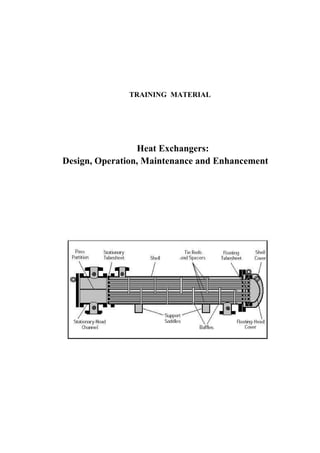
  • 16. 16 2 Classification of heat exchangers i Easily by disassembly, no cleaning problem ii Suitable for high pressure fluid, (the pressure containment in the small diameter pipe or tubing is a less costly method compared to a large diameter shell.) Limitation: The double pipe heat exchanger is generally used for the application where the total heat transfer surface area required is less than or equal to 20 m2 (215 ft2 ) because it is expensive on a cost per square meter (foot) basis. 2.3 Spiral tube heat exchanger Spiral tube heat exchanger consists of one or more spirally wound coils fitted in a shell (Fig. 2.3). Heat transfer associated with spiral tube is higher than than that for a straight tube . In addition, considerable amount of surface area can be accommodated in a given space by spiralling. Thermal expansion is no problem but cleaning is almost impossible. Figure 2.3. Spiral tube heat exchanger. Courtesy of The German Atlas 2.4 Shell and tube heat exchanger Shell and tube heat exchanger is built of round tubes mounted in a cylindrical shell with the tube axis parallel to that of the shell. One fluid flow inside the tube, the other flow across and along the tubes. The major components of the shell and tube heat exchanger are tube bundle, shell, front end head, rear end head, baffles and tube sheets (Fig.2.4). Figure 2.4. Shell and tube heat exchanger Dr. Ali A. Rabah, Dept of Chemeng, U of K, Email : rabahss@hotamil.com
  • 17. 2.4 Shell and tube heat exchanger 17 The shell and tube heat exchanger is further divided into three catogaries as 1. Fixed tube sheet 2. U tube 3. Floating head 2.4.1 Fixed tubesheet A fixed-tubesheet heat exchanger (Figure 2.5) has straight tubes that are secured at both ends to tubesheets welded to the shell. The construction may have removable channel covers , bonnet-type channel covers , or integral tubesheets. The principal advantage of the fixedtubesheet construction is its low cost because of its simple construction. In fact, the fixed tubesheet is the least expensive construction type, as long as no expansion joint is required. Figure 2.5. Fixed-tubesheet heat exchanger. Other advantages are that the tubes can be cleaned mechanically after removal of the channel cover or bonnet, and that leakage of the shellside fluid is minimized since there are no flanged joints. A disadvantage of this design is that since the bundle is fixed to the shell and cannot be removed, the outsides of the tubes cannot be cleaned mechanically. Thus, its application is limited to clean services on the shellside. However, if a satisfactory chemical clean- ing program can be employed, fixed-tubesheet construction may be selected for fouling services on the shellside. In the event of a large differential temperature between the tubes and the shell, the tubesheets will be unable to absorb the differential stress, thereby making it necessary to incorporate an expansion joint. This takes away the advantage of low cost to a significant extent. 2.4.2 U-tube As the name implies, the tubes of a U-tube heat exchanger (Figure 2.6) are bent in the shape of a U. There is only one tubesheet in a Utube heat exchanger. However, the lower cost for the single tubesheet is offset by the additional costs incurred for the bending of the tubes and the somewhat larger shell diameter (due to the minimum U-bend radius), making the cost of a U-tube heat exchanger comparable to that of a fixedtubesheet exchanger. Dr. Ali A. Rabah, Dept of Chemeng, U of K, Email : rabahss@hotamil.com
  • 18. 18 2 Classification of heat exchangers The advantage of a U-tube heat exchanger is that because one end is free, the bundle can expand or contract in response to stress differentials. In addition, the outsides of the tubes can be cleaned, as the tube bundle can be removed. The disadvantage of the U-tube construction is that the insides of the tubes cannot be cleaned effectively, since the U-bends would require flexible- end drill shafts for cleaning. Thus, U-tube heat exchangers should not be used for services with a dirty fluid inside tubes. Figure 2.6. U-tube heat exchanger. 2.4.3 Floating head The floating-head heat exchanger is the most versatile type of STHE, and also the costliest. In this design, one tubesheet is fixed relative to the shell, and the other is free to ”float” within the shell. This permits free expansion of the tube bundle, as well as cleaning of both the insides and outsides of the tubes. Thus, floating-head SHTEs can be used for services where both the shellside and the tubeside fluids are dirty-making this the standard construction type used in dirty services, such as in petroleum refineries. There are various types of floating- head construction. The two most common are the pull-through with backing device and pullthrough without backing service designs. The design (Figure 2.7) with backing service is the most common configuration in the chemical process industries (CPI). The floating-head cover is secured against the floating tubesheet by bolting it to an ingenious split backing ring. This floating-head closure is located beyond the end of the shell and contained by a shell cover of a larger diameter. To dismantle the heat exchanger, the shell cover is removed first, then the split backing ring, and then the floating-head cover, after which the tube bundle can be removed from the stationary end. Dr. Ali A. Rabah, Dept of Chemeng, U of K, Email : rabahss@hotamil.com
  • 19. 2.5 Plate heat exchangers 19 Figure 2.7. Floating head with packing service. In the design without packing service construction (Figure 2.8), the entire tube bundle, including the floating-head assembly, can be removed from the stationary end, since the shell diameter is larger than the floating-head flange. The floatinghead cover is bolted directly to the floating tubesheet so that a split backing ring is not required. The advan- tage of this construction is that the tube bundle may be removed from the shell without removing either the shell or the floatinghead cover, thus reducing maintenance time. This design is particularly suited to kettle reboilers having a dirty heating medium where U- tubes cannot be employed. Due to the enlarged shell, this construction has the highest cost of all exchanger types. Figure 2.8. Floating head without packing service. 2.5 Plate heat exchangers These exchangers are generally built of thin plates. The plate are either smooth or have some form of corrugations and they are either flat or wound in exchanger. Generally Dr. Ali A. Rabah, Dept of Chemeng, U of K, Email : rabahss@hotamil.com
  • 20. 20 2 Classification of heat exchangers theses exchanger cannot accomodate high pressure/temperature differential relative the tubular exchanger. This type of exchanger is further classified as: • Gasketed plate • Fixed plate • Spiral plate 2.5.1 Gasketed plate heat exchanger Gasketed plate heat exchanger (see Fig. 2.9) consists of a series of corrugated alloy material channel plates, bounded by elastomeric gaskets are hung off and guided by lon- gitudinal carrying bars, then compressed by large-diameter tightening bolts between two pressure retaining frame plates (cover plates). Figure 2.9. Plate heat exchanger The frame and channel plates have portholes which allow the process fluids to enter alter- nating flow passages (the space between two adjacent-channel plates) Fig.2.10. Gaskets around the periphery of the channel plate prevent leakage to the atmosphere and also pre- vent process fluids from coming in contact with the frame plates. No inter fluid leakage is possible in the port area due to a dual-gasket seal. Fig.2.11 shows the plate profiles. Expansion of the initial unit is easily performed in the field without special considerations. The original frame length typically has an additional capacity of 15-20 percent more channel plates (i.e. surface area). In fact, if a known future capacity is available during fabrication stages, a longer carrying bar could be installed, and later, increasing the surface area would be easily handled. When the expansion is needed, simply untighten the carrying bolts, pull back the frame plate, add the additional channel plates, and tighten the frame plate. Dr. Ali A. Rabah, Dept of Chemeng, U of K, Email : rabahss@hotamil.com
  • 21. 2.5 Plate heat exchangers 21 Figure 2.10. Plate heat exchanger flow configuration Applications: Most PHE applications are liquid-liquid services but there are numerous steam heater and evaporator uses from their heritage in the food industry. Industrial users typically have chevron style channel plates while some food applications are washboard style. Fine particulate slurries in concentrations up to 70 percent by weight are possible with standard channel spacings. Wide-gap units are used with larger particle sizes. Typical particle size should not exceed 75 percent of the single plate (not total channel) gap. Close temperature approaches and tight temperature control possible with PHE’s and the ability to sanitize the entire heat transfer surface easily were a major benefit in the food and pharmaceutical industry. Advantages: - • Easily assembled and dismantled • Easily cleaned both chemically and mechanically • Flexible (the heat transfer can be changed as required) • Can be used for multiple service as required • Leak is immediately deteced since all plates are vented to the atmosphere, and the fluid split on the floor rather than mixing with other fluid • Heat transfer coefficient is larger and hence small heat transfer area is required than STHE • The space required is less than that for STHE for the same duty • Less fouling due to high turbulent flow Dr. Ali A. Rabah, Dept of Chemeng, U of K, Email : rabahss@hotamil.com
  • 22. 22 2 Classification of heat exchangers Figure 2.11. Plate and frame of a plate heat exchanger • Very close temperature approach can be obtained • low hold up volume • LMTD is fully utilized • More economical when material cost are high Disadvantages: - • Low pressure <30 bar (plate deformation) • Working temperature of < (500 F) [250 o C] (maximum gasket temperature) see table 2.1. Table 2.1. Plate Heat Exchanger Gasket Materials Material Common name Temperature limit (F) Styrene-Butadiene Buna-S 185 Neoprene Neoprene 250 Acrylonitrile- Butadiene Buna-N 275 Ethylene/Propylene EPDM 300 Fluorocarbon Viton 300 Resin-Cured Butyl Resin-Cured Butyl 300 Compressed Asbestos Compressed Asbestos 500 2.5.2 Welded- and Brazed-Plate exchanger (W. PHE and BHE) To overcome the gasket limitations, PHE manufacturers have developed welded-plate exchangers. There are numerous approaches to this solution: weld plate pairs together with the other fluid-side conventionally gasketed, weld up both sides but use a horizonal Dr. Ali A. Rabah, Dept of Chemeng, U of K, Email : rabahss@hotamil.com
  • 23. 2.5 Plate heat exchangers 23 stacking of plates method of assembly, entirely braze the plates together with copper or nickel brazing, diffusion bond then pressure form plates and bond etched, passage plates Fig. 2.12 and Fig. 2.13. Typical applications include district heating where the low cost and minimal maintenance have made this type of heat exchanger especially attractive. Figure 2.12. Welded or blazed plate heat exchanger Figure 2.13. Fin-Plate heat exchanger Most methods of welded-plate manufacturing do not allow for inspection of the heat- transfer surface, mechanical cleaning of that surface, and have limited ability to repair or plug off damage channels. Consider these limitations when the fluid is heavily fouling, has solids, or in general the repair or plugging ability for severe services. 2.5.3 Spiral Plate Exchanger (SPHE) The spiral-plate heat exchanger (SHE) may be one exchanger selected primarily on its virtues and not on its initial cost. SPHEs offer high reliability and on-line performance in many severely fouling services such as slurries. The SHE is formed by rolling two strips Dr. Ali A. Rabah, Dept of Chemeng, U of K, Email : rabahss@hotamil.com
  • 24. 24 2 Classification of heat exchangers of plate, with welded-on spacer studs, upon each other into clock-spring shape Fig.2.14 and Fig.2.15. This forms two passages. Passages are sealed off on one end of the SHE by welding a bar to the plates; hot and cold fluid passages are sealed off on opposite ends of the SHE. A single rectangular flow passage is now formed for each fluid, producing very high shear rates compared to tubular designs. Removable covers are provided on each end to access and clean the entire heat transfer surface. Figure 2.14. Spiral Plate heat exchanger Pure countercurrent flow is achieved and LMTD correction factor is essentially = 1.0. Since there are no dead spaces in a SHE, the helical flow pattern combines to entrain any solids and create high turbulence creating a self-cleaning flow passage. There are no thermal-expansion problems in spirals. Since the center of the unit is not fixed, it can torque to relieve stress. The SHE can be expensive when only one fluid requires a Dr. Ali A. Rabah, Dept of Chemeng, U of K, Email : rabahss@hotamil.com
  • 25. 2.5 Plate heat exchangers 25 high alloy material. Since the heat-transfer plate contacts both fluids, it is required to be fabricated out of the higher alloy. SHEs can be fabricated out of any material that can be cold-worked and welded. The channel spacings can be different on each side to match the flow rates and pressure drops of the process design. The spacer studs are also adjusted in their pitch to match the fluid characteristics. As the coiled plate spirals outward, the plate thickness increases from a minimum of 2 mm to a maximum (as required by pressure) up to 10 mm. This means relatively thick material separates the two fluids compared to tubing of conventional exchangers. a) Spiral flow in both channels b) Flow are both spiral and axial Figure 2.15. Spiral Plate heat exchanger Applications: The most common applications that fit SHE are slurries. The rectan- gular channel provides high shear and turbulence to sweep the surface clear of blockage and causes no distribution problems associated with other exchanger types. A localized restriction causes an increase in local velocity which aids in keeping the unit free flowing. Only fibers that are long and stringy cause SHE to have a blockage it cannot clear itself. As an additional antifoulant measure, SHEs have been coated with a phenolic lining. This provides some degree of corrosion protection as well, but this is not guaranteed due to pinholes in the lining process. There are three types of SHE to fit different applications: • Type I is the spiral-spiral flow pattern (Fig. 2.15a). It is used for all heating and cooling services and can accommodate temperature crosses such as lean/rich services in one unit. The removable covers on each end allow access to one side at a time to perform maintenance on that fluid side. Never remove a cover with one side under pressure as the unit will telescope out like a collapsible cup. Dr. Ali A. Rabah, Dept of Chemeng, U of K, Email : rabahss@hotamil.com
  • 26. 26 2 Classification of heat exchangers • Type II units are the condenser and reboiler designs (Fig. 2.15b). One side is spiral flow and the other side is in cross flow. These SHEs provide very stable designs for vacuum condensing and reboiling services. A SHE can be fitted with special mounting connections for reflux-type ventcondenser applications. The vertically mounted SHE directly attaches on the column or tank. • Type III units are a combination of the Type I and Type II where part is in spiral flow and part is in cross flow. This SHE can condense and subcool in a single unit. The unique channel arrangement has been used to provide on-line cleaning, by switching fluid sides to clean the fouling (caused by the fluid that previously flowed there) off the surface. Phosphoric acid coolers use pond water for cooling and both sides foul; water, as you expect, and phosphoric acid deposit crystals. By reversing the flow sides, the water dissolves the acid crystals and the acid clears up the organic fouling. SHEs are also used as oleum coolers, sludge coolers/ heaters, slop oil heaters, and in other services where multiple flow- passage designs have not performed well. 2.6 Extended surface The tubular and plate exchangers described previously are all prime surface heat exchang- ers. The design thermal effectiveness is usually 60 % and below and the heat transfer area density is usually less than 300 m2 m3 . In many application an effectiveness of up to 90 % is essential and the box volume and mass are limited so that a much more compact surface is mandated. Usually either a gas or a liquid having a low heat transfer coefficient is the fluid on one or both sides. This results in a large heat transfer area requirements. for low density fluid (gases), pressure drop constraints tend to require a large flow area. so a question arises how can we increase both the surface area and flow area together in a reasonably shaped configuration. The surface area may be increased by the fins. The flow area is increased by the use of thin gauge material and sizing the core property. There are two most common types of extended surface heat exchangers. These are • Plate-fin • Tube-fin 2.6.1 Plate fin Plate -fin heat exchanger has fins or spacers sandwiched between parallel plates (refereed to as parting plates or parting sheets) or formed tubes as shown in fig. 2.16(left). While the plates separate the two fluid streams, the fins form the individual flow passages. Fins are used on both sides in a gas-gas heat exchanger. In gas-liquid applications fins are used in the gas side. Figure 2.17. Finned tube heat exchanger Dr. Ali A. Rabah, Dept of Chemeng, U of K, Email : rabahss@hotamil.com
  • 27. 2.6 Extended surface 27 Figure 2.16. Examples of extended surfaces on one or both sides. Plate fins on both sides (left) and Tubes and plate fins (right). 2.6.2 Tube fin In tube fin heat exchanger, tubes of round, rectangular, or elliptical shape are generally used. Fins are generally used on the outside and also used inside the tubes in some applications. they are attached to the tube by tight mechanical fit, tension wound, gluing, soldering, brazing, welding or extrusion. Tube fin exchanger is shown in Fig. 2.16(right) and Fig.2.17 Dr. Ali A. Rabah, Dept of Chemeng, U of K, Email : rabahss@hotamil.com
  • 28. 28 3 Code and standards 3 Code and standards The objective of codes and standards are best described by ASME: The objectives of code rules and standards (apart from fixing dimensional values) is to achieve minimum requirements for safe construction, in other words, to provide public protection by defining those materials, design, fabrication and inspection requirements; whose omission may radically increase operating hazards.... Experience with code rules has demonstrated that the probability of disastrous failure can be reduced to the extremely low level necessary to protect life and property by suitable minimum requirements and safety factors. Obviously, it is impossible for general rules to anticipate other than conventional service,.... Suitable precautions are therefore entirely the responsibility of the design engineer guided by the needs and specifications of the user. Over years a number of standardization bodies have been developed by individual country, manufacturers and designers to lay down nomenclatures for the size and type of shell and tube heat exchangers. These include among other • TEMA standards (Tubular Exchanger Manufacturer Association., 1998)[147] • HEI standards (Heat Exchanger Institute, 1980), • API (American Petroleum Institute). • Other national standards include the German (DIN), Japan, India, to mention a few. In this work, being most widely used one, the TEMA standard is presented. 3.1 TEMA Designations In order to understand the design and operation of the shell and tube heat exchanger, it is important to know the nomenclature and terminology used to describe them and the various parts that go to their construction. Only then we can understand the design and reports given by the researchers, designers, manufacturer and users. It is essential for the designer to have a good working knowledge of the mechanical features of STHEs and how they influence thermal design. The principal components of an STHE are: • shell; • shell cover; • tubes; • channel; • channel cover; • tubesheet; • baffles; and • nozzles. Other components include tie-rods and spacers, pass partition plates, impingement plate, longitudinal baffle, sealing strips, supports, and foundation. Table 3.1 shows the nomen- clature used for different parts of shell and tube exchanger in accordance with TEMA standards; the numbers refer to the feature shown in Fig. 3.2 to Fig. 3.8. Dr. Ali A. Rabah, Dept of Chemeng, U of K, Email : rabahss@hotamil.com
  • 29. 3.1 TEMA Designations 29 Table 3.1. TEAM notations Index Notation Index Notation 1 stationary head- channel 20 slip on backing flange 2 stationary head- bonnet 21 floating head cover-external 3 stationary head flange-chennel or bonnet 22 floating tube sheet skirt 4 channel cover 23 packing box 5 stationary head - nozzle 24 packing 6 stationary tube sheet 25 packing gland 7 tubes 26 latern ring 8 shell 27 tie rods and spacers 9 shell cover 28 traverse baffle or support plate 10 shell flange-stationary head end 29 impingement plate 11 shell flange-rear head end 30 longitudinal baffle 12 shell nozzle 31 pass partition 13 shell cover flange 32 vent connection 14 expansion joint 33 drain connection 15 floating tube sheet 34 instrument connection 16 floating head cover 35 support saddle 17 floating head flange 36 lifting lug 18 floating head backing device 37 support bracket 19 split shear ring 38 weir 39 liquid level connection Because of the number of variations in mechanical designs for front and rear heads and shells, and for commercial reasons, TEMA has divided STHE into main three components: front head, shell and rear head. Fig. 3.1 illustrates TEMA nomenclature for the various construction possibilities. TEMA has classified the front head channel and bonnet types as given the letters (A,B,C,N,D) and the shell is classified according to the nozzles locations for the inlet and outlet. There are type of shell configuration ( E,F,G,H,J,K,X). Similarly the rear head is classified ( M,N,P,S,T,U,W). Exchangers are described by the letter codes of the three sections. The first letter stands for the front head, the second letter for the shell type and the third letter for the rear head type. For example a BFL exchanger has a bonnet cover, two-shell pass with longitudinal baffles and a fixed tube sheet rear head. In addition to these the size of the exchanger is required to be identified with the notation. The size is identified by the shell inside diameter (nominal) and tube length (both are rounded to the nearest integer in inch or mm). Demonstration examples are shown below: • Type AES size 23-192 in (590-4880): This exchanger has a removable channel cover (A), single pass shell (E) and Split ring floating front head (S) it has , 23 in (590 mm) inside diameter with tubes of 16 ft (4880 mm) long. • Type BGU Size 19-84 (480-2130)This exchanger has a bonnet-type stationary front head (B), split flow shell (G) and U-tube bundle rear head(U) with 19 in (480) inside diameter and 7 ft (2130 mm) tube length. • Type AFM size 33-96 (840-2440): This exchanger has a removable channel and cover front head (A), two-pass shell (F) and fixed tube sheet bonnet-type rear head (M) with 331/8 in (840 mm) inside diameter and 8ft (2440 mm) tube length. Dr. Ali A. Rabah, Dept of Chemeng, U of K, Email : rabahss@hotamil.com
  • 30. 30 3 Code and standards Figure 3.1. TEMA-type designations for shell-and-tube heat exchangers. (Standards of Tubu- lar Exchanger Manufacturers Association, 6th ed., 1978.) In the above illustration the term single pass and two pass shell have been used. This mean that the shell side fluid travels only one through the shell (single pass) or twice (two pass shell). Two pass shell mean that the fluid enters at one end, travel to other end and back to the end where it entered (making U-turn). Similarly there are multiple pases. To be remembered is that the number of tube passes is equal to or greater than the number of shell passes. Generally the multi shell and tube passes are usually designated by two numerals separated by a hyphen, with the first numeral indication the number of shell pass and the other stands for the tube passes. For example a one-shell pass and two tube pass AEL exchanger will be written as 1-2 AEL. To be remembered is that this not an TEMA standards. TEMA requires the number of shell and tube passes to be spelled out Dr. Ali A. Rabah, Dept of Chemeng, U of K, Email : rabahss@hotamil.com
  • 31. 3.1 TEMA Designations 31 as in the pervious examples. In a heat exchanger specification sheet there is a space for indicating the number of shell and tube passes. Another identification of the shell and tube heat exchanger is the number of shell passes. 1 shell pass, 2 shell pass, etc. This is not a TEMA standardization. The tube passes can be equal to or greater than the shell pass. Dr. Ali A. Rabah, Dept of Chemeng, U of K, Email : rabahss@hotamil.com
  • 32. 32 3 Code and standards Table3.2.FeaturesofTEMAShell-and-Tube-TypeExchangers. PackedInternalOutside TypeFixedlantern-ringfloatingheadpackedPull-through ofdesigntubesheetU-tubefloatinghead(splitbackingring)floatingheadfloatinghead T.E.M.A.rear -headtypeLorMorNUWSPT Relativecostincreases fromA(least expensive)through E(mostexpensive)BACEDE Provisionfor differentialexpansionExpansionIndividualtubesFloatingheadFloatingheadFloatingheadFloatinghead jointinfreetoexpand shell RemovablebundleNoYesYesYesYesYes Replacementbundle possibleNoYesYesYesYesYes Individualtubes replaceableYesOnlythoseinYesYesYesYes outsiderow Tubecleaningby chemicalsinside andoutsideYesYesYesYesYesYes Interiortube cleaningmechanicallyYesSpecialtoolsrequiredYesYesYesYes Exteriortube cleaningmechanically: TriangularpitchNoNoNoNoNoNo SquarepitchNoYesYesYesYesYes Hydraulic-jet cleaning: TubeinteriorYesSpecialtoolsrequiredYesYesYesYes TubeexteriorNoYesYesYesYesYes Doubletube sheetfeasibleYesYesNoNoYesNo NumberoftubepassesNopracticalAnyevenLimitedtooneNopracticalNopracticalNopractical limitationsnumberpossibleortwopasseslimitationslimitationslimitations Internalgaskets eliminatedYesYesYesNoYesNo Dr. Ali A. Rabah, Dept of Chemeng, U of K, Email : rabahss@hotamil.com
  • 33. 3.2 Classification by construction STHE 33 3.2 Classification by construction STHE Fig. 3.2 to Fig. 3.8 show details of the construction of the TEMA types of shell-and-tube heat exchangers. These types are: • Fixed tube sheet • U-tube • Floating head 3.2.1 Fixed tube sheet Fixed-tube-sheet exchangers (Fig. 3.2) are used more often than any other type, and the frequency of use has been increasing in recent years. The tube sheets are welded to the shell. Usually these extend beyond the shell and serve as flanges to which the tube-side headers are bolted. This construction requires that the shell and tube-sheet materials be weldable to each other. When such welding is not possible, a blind-gasket type of construction is utilized. The blind gasket is not accessible for maintenance or replacement once the unit has been constructed. This construction is used for steam surface condensers, which operate under vacuum. Figure 3.2. Heat-exchanger-component nomenclature. Fixed tube heat sheet shell and tube heat exchanger. (Standard of Tubular Exchanger Manufacturers Association, 6th ed., 1978.) The tube-side header (or channel) may be welded to the tube sheet, as shown in Fig. 3.1 for type C and N heads. This type of construction is less costly than types B and M or A and L and still offers the advantage that tubes may be examined and replaced without disturbing the tube-side piping connections. There is no limitation on the number of tube-side passes. Shell-side passes can be one or more, although shells with more than two shell side passes are rarely used. Tubes can completely fill the heat-exchanger shell. Clearance between the outermost tubes and the shell is only the minimum necessary for fabrication. Between the inside of the shell and the baffles some clearance must be provided so that baffles can slide into the shell. Fabrication tolerances then require some additional clearance between the outside of the baffles and the outermost tubes. The edge distance between the outer tube limit (OTL) and the baffle diameter must be sufficient to prevent vibration of the tubes from breaking through the baffle holes. The outermost tube must be contained within the OTL. Clearances between the inside shell diameter and OTL are 13 mm (1/2 in) for 635-mm- (25-in-) inside-diameter shells and up, 11 mm for 254- through 610-mm (10- through 24-in) pipe shells, and slightly less for smaller-diameter pipe shells. Dr. Ali A. Rabah, Dept of Chemeng, U of K, Email : rabahss@hotamil.com
  • 34. 34 3 Code and standards Tubes can be replaced. Tube-side headers, channel covers, gaskets, etc., are accessible for maintenance and replacement. Neither the shell-side baffle structure nor the blind gasket is accessible. During tube removal, a tube may break within the shell. When this occurs, it is most difficult to remove or to replace the tube. The usual procedure is to plug the appropriate holes in the tube sheets. Differential expansion between the shell and the tubes can develop because of differences in length caused by thermal expansion. Various types of expansion joints are used to eliminate excessive stresses caused by expansion. The need for an expansion joint is a function of both the amount of differential expansion and the cycling conditions to be expected during operation. A number of types of expansion joints are available (Fig. 3.3) Figure 3.3. Expansion joints. . a Flat plates. Two concentric flat plates with a bar at the outer edges. The flat plates can flex to make some allowance for differential expansion. This design is generally used for vacuum service and gauge pressures below 103 kPa (15 lbf/in2). All welds are subject to severe stress during differential expansion. b Flanged-only heads. The flat plates are flanged (or curved). The diameter of these heads is generally 203 mm (8 in) or more greater than the shell diameter. The welded joint at the shell is subject to the stress referred to before, but the joint Dr. Ali A. Rabah, Dept of Chemeng, U of K, Email : rabahss@hotamil.com
  • 35. 3.2 Classification by construction STHE 35 connecting the heads is subjected to less stress during expansion because of the curved shape. c Flared shell or pipe segments. The shell may be flared to connect with a pipe section, or a pipe may be halved and quartered to produce a ring. d Formed heads. A pair of dished-only or elliptical or flanged and dished heads can be used. These are welded together or connected by a ring. This type of joint is similar to the flanged-only-head type but apparently is subject to less stress. e Flanged and flued heads. A pair of flanged-only heads is provided with concentric reverse flue holes. These heads are relatively expensive because of the cost of the fluing operation. The curved shape of the heads reduces the amount of stress at the welds to the shell and also connecting the heads. f Toroidal. The toroidal joint has a mathematically predictable smooth stress pat- tern of low magnitude, with maximum stresses at sidewalls of the corrugation and minimum stresses at top and bottom. The foregoing designs were discussed as ring expansion joints by Kopp and Sayre, Expansion Joints for Heat Exchangers (ASME Misc. Pap., vol. 6, no. 211). All are statically indeterminate but are subjected to analysis by introducing various simplifying assumptions. Some joints in current industrial use are of lighter wall construction than is indicated by the method of this paper. g Bellows. Thin-wall bellows joints are produced by various manufacturers. These are designed for differential expansion and are tested for axial and transverse movement as well as for cyclical life. Bellows may be of stainless steel, nickel alloys, or copper. (Aluminum, Monel, phosphor bronze, and titanium bellows have been manufac- tured.) Welding nipples of the same composition as the heat-exchanger shell are generally furnished. The bellows may be hydraulically formed from a single piece of metal or may consist of welded pieces. External insulation covers of carbon steel are often provided to protect the light-gauge bellows from damage. The cover also prevents insulation from interfering with movement of the bellows (see h). h Toroidal bellows. For high-pressure service the bellows type of joint has been modi- fied so that movement is taken up by thin-wall small-diameter bellows of a toroidal shape. Thickness of parts under high pressure is reduced considerably (see f ). Improper handling during manufacture, transit, installation, or maintenance of the heat exchanger equipped with the thin-wallbellows type or toroidal type of expansion joint can damage the joint. In larger units these light-wall joints are particularly susceptible to damage, and some designers prefer the use of the heavier walls of formed heads. Chemical-plant exchangers requiring expansion joints most commonly have used the flanged-and-flued-head type. There is a trend toward more common use of the light- wall-bellows type. 3.2.2 U-Tube Heat Exchanger Fig. 3.4 shows U-tube heat exchanger Type CFU. The tube bundle consists of a stationary tube sheet, U tubes (or hairpin tubes), baffles or support plates, and appropriate tie rods and spacers. The tube bundle can be removed from the heat-exchanger shell. A tube-side header (stationary head) and a shell with integral shell cover, which is welded to the shell, are provided. Each tube is free to expand or contract without any limitation being placed upon it by the other tubes. The U-tube bundle has the advantage of providing minimum clearance between the outer tube limit and the inside of the shell for any of the removable-tube-bundle constructions. Clearances are of the same magnitude as for fixed-tube-sheet heat exchangers. The number of tube holes in a given shell is less than Dr. Ali A. Rabah, Dept of Chemeng, U of K, Email : rabahss@hotamil.com
  • 36. 36 3 Code and standards that for a fixed-tube-sheet exchanger because of limitations on bending tubes of a very short radius. Figure 3.4. Heat-exchanger-component nomenclature. U-tube heat exchanger. Type CFU. (Standard of Tubular Exchanger Manufacturers Association, 6th ed., 1978.) The U-tube design offers the advantage of reducing the number of joints. In high-pressure construction this feature becomes of considerable importance in reducing both initial and maintenance costs. The use of U-tube construction has increased significantly with the development of hydraulic tube cleaners, which can remove fouling residues from both the straight and the U-bend portions of the tubes. Rods and conventional mechanical tube cleaners cannot pass from one end of the U tube to the other. Power-driven tube cleaners, which can clean both the straight legs of the tubes and the bends, are available. Hydraulic jetting with water forced through spray nozzles at high pressure for cleaning tube interiors and exteriors of removal bundles is reported in the recent ASME publications. U-tube can be used for high pressure and high temperature application like kettle reboiler, evaporator, tank section heaters ,etc. The tank suction heater, as illustrated in Fig. 3.5, contains a U-tube bundle. This design is often used with outdoor storage tanks for heavy fuel oils, tar, molasses, and similar fluids whose viscosity must be lowered to permit easy pumping. Uusally the tube-side heating medium is steam. One end of the heater shell is open, and the liquid being heated passes across the outside of the tubes. Pumping costs can be reduced without heating the entire contents of the tank. Bare tube and integral low-fin tubes are provided with baffles. Longitudinal fin-tube heaters are not baffled. Fins are most often used to minimize the fouling potential in these fluids. Dr. Ali A. Rabah, Dept of Chemeng, U of K, Email : rabahss@hotamil.com
  • 37. 3.2 Classification by construction STHE 37 Figure 3.5. Heat-exchanger-component nomenclature. U-tube heat exchanger. Type CFU. (Standard of Tubular Exchanger Manufacturers Association, 6th ed., 1978.) Kettle-type reboilers, evaporators, etc. , are often U-tube exchangers with enlarged shell sections for vapor-liquid separation (Fig.3.6). The U-tube bundle replaces the floating- heat bundle of Fig. 3.4. Figure 3.6. Kettle reboiler The U-tube exchanger with copper tubes, cast-iron header, and other parts of carbon steel is used for water and steam services in office buildings, schools, hospitals, hotels, etc. Nonferrous tube sheets and admiralty or 90-10 copper-nickel tubes are the most frequently used substitute materials. These standard exchangers are available from a number of manufacturers at costs far below those of custombuilt process-industry equipment. 3.2.3 Floating Head Designs In an effort to reduce thermal stresses and provide a means to remove the tube bundle for cleaning, several floating rear head designs have been established. The simplest is a Dr. Ali A. Rabah, Dept of Chemeng, U of K, Email : rabahss@hotamil.com
  • 38. 38 3 Code and standards Internal floating head (pull- through design) Fig3.9 design which allows the tube bundle to be pulled entirely through the shell for service or replacement. In order to accommodate the rear head bolt circle, tubes must be removed resulting in a less efficient use of shell size. In addition, the missing tubes result in larger annular spaces and can contribute to reduced flow across the effective tube surface, resulting in reduced thermal performance. Some designs include sealing strips installed in the shell to help block the bypass steam. Another floating head design that partially addresses the above disadvantages is a split- ring floating head. Here the floating head bonnet is bolted to a split backing ring instead of the tube sheet. This eliminates the bolt circle diameter and allows a full complement of tubes to fill the shell. This construction is more expensive than a common pull through design, but is in wide use in petrochemical applications. For applications with high pressures or temperatures, or where more positive sealing between the fluids is desired, the pull-through design should be specified. Two other types, the outside packed lantern ring and the outside packed stuffing box designs offer less positive sealing against leakage to the atmosphere than the pull though or split ring designs, but can be configured for single tube pass duty. More details about the various types of floating head shell and tube heat exchanger is given the following sections Packed-Lantern-Ring Exchanger: (Fig. 3.7 ) This construction is the least costly of the straight-tube removable bundle types. The shell- and tube-side fluids are each contained by separate rings of packing separated by a lantern ring and are installed at the floating tube sheet. The lantern ring is provided with weep holes. Any leakage passing the packing goes through the weep holes and then drops to the ground. Leakage at the packing will not result in mixing within the exchanger of the two fluids. The width of the floating tube sheet must be great enough to allow for the packings, the lantern ring, and differential expansion. Sometimes a small skirt is attached to a thin tube sheet to provide the required bearing surface for packings and lantern ring. The clearance between the outer tube limit and the inside of the shell is slightly larger than that for fixed-tube-sheet and U-tube exchangers. The use of a floating-tube-sheet skirt increases this clearance. Without the skirt the clearance must make allowance for tubehole distortion during tube rolling near the outside edge of the tube sheet or for tube-end welding at the floating tube sheet. The packed-lantern-ring construction is generally limited to design temperatures below 191◦ C (375◦ F) and to the mild services of water, steam, air, lubricating oil, etc. Design gauge pressure does not exceed 2068 kPa (300 lbf/in2 ) for pipe shell exchangers and is limited to 1034 kPa (150 lbf/in2 ) for 610- to 1067-mm- (24- to 42-in-) diameter shells. Dr. Ali A. Rabah, Dept of Chemeng, U of K, Email : rabahss@hotamil.com
  • 39. 3.2 Classification by construction STHE 39 Figure 3.7. Heat-exchanger-component nomenclature. Exchanger with packed floating tube sheet and lantern ring. Type AJW. External floating head design. (Standard of Tubular Ex- changer Manufacturers Association, 6th ed., 1978.) Outside-Packed Floating-Head Exchanger: (Fig. 3.8) The shell-side fluid is con- tained by rings of packing, which are compressed within a stuffing box by a packing follower ring. This construction was frequently used in the chemical industry, but in recent years usage has decreased. The removable-bundle construction accommodates dif- ferential expansion between shell and tubes and is used for shell-side service up to 4137 kPa gauge pressure (600 lbf/in2) at 316◦ C (600◦ F). Figure 3.8. Heat-exchanger-component nomenclature. Outside-packed floating-head ex- changer. Type AEP. (Standard of Tubular Exchanger Manufacturers Association, 6th ed., 1978.) There are no limitations upon the number of tube-side passes or upon the tube-side design pressure and temperature. The outside-packed floating-head exchanger was the most commonly used type of removable- bundle construction in chemical-plant service. The floating-tube-sheet skirt, where in contact with the rings of packing, has fine machine finish. A split shear ring is inserted into a groove in the floating-tube-sheet skirt. A slip- on backing flange, which in service is held in place by the shear ring, bolts to the external floating- head cover. The floating-head cover is usually a circular disk. With an odd number of tube-side passes, an axial nozzle can be installed in such a floating- head cover. If a side nozzle is required, the circular disk is replaced by either a dished head or a channel barrel (similar to Fig. 11-36f ) bolted between floating-head cover and floating-tube-sheet skirt. The outer tube limit approaches the inside of the skirt but is farther removed from the inside of the shell than for any of the previously discussed constructions. Clearances Dr. Ali A. Rabah, Dept of Chemeng, U of K, Email : rabahss@hotamil.com
  • 40. 40 3 Code and standards between shell diameter and bundle OTL are 22 mm (7.8 in) for small-diameter pipe shells, 44 mm (1e in) for large-diameter pipe shells, and 58 mm (2g in) for moderatediameter plate shells. Internal Floating-Head Exchanger: (Fig. 3.9) The internal floating-head design is used extensively in petroleum-refinery service, but in recent years there has been a decline in usage. The tube bundle is removable, and the floating tube sheet moves (or floats) to accommodate differential expansion between shell and tubes. The outer tube limit approaches the inside diameter of the gasket at the floating tube sheet. Clearances (between shell and OTL) are 29 mm for pipe shells and 37 mm for moderatediameter plate shells. A split backing ring and bolting usually hold the floating-head cover at the floating tube sheet. These are located beyond the end of the shell and within the larger-diameter shell cover. Shell cover, split backing ring, and floating-head cover must be removed before the tube bundle can pass through the exchanger shell. With an even number of tube-side passes the floating-head cover serves as return cover for the tube-side fluid. With an odd number of passes a nozzle pipe must extend from the floating-head cover through the shell cover. Provision for both differential expansion and tube-bundle removal must be made. Figure 3.9. Heat-exchanger-component nomenclature. Internal floating head (pull- through design). Type AES. (Standard of Tubular Exchanger Manufacturers Association, 6th ed., 1978.) Figure 3.10. Heat-exchanger-component nomenclature. Exchanger with packed floating tube sheet and lantern ring. Type AES. (Standard of Tubular Exchanger Manufacturers Association, 6th ed., 1978.) Pull-Through Floating-Head Exchanger: (Fig. 3.12) Construction is similar to that of the internal-floating-head split-backing ring exchanger except that the floating-head Dr. Ali A. Rabah, Dept of Chemeng, U of K, Email : rabahss@hotamil.com
  • 41. 3.3 Shell Constructions 41 cover bolts directly to the floating tube sheet. The tube bundle can be withdrawn from the shell without removing either shell cover or floating-head cover. This feature reduces maintenance time during inspection and repair. The large clearance between the tubes and the shell must provide for both the gasket and the bolting at the floating-head cover. This clearance is about 2 to 2.5 times that required by the split-ring design. Sealing strips or dummy tubes are often installed to reduce bypassing of the tube bundle. Figure 3.11. Heat-exchanger-component nomenclature. Kettle-type floating-head reboiler. Type AKT. (Standard of Tubular Exchanger Manufacturers Association, 6th ed., 1978.) 3.3 Shell Constructions • The most common TEMA shell type is the E shell as it is most suitable for most industrial process cooling applications. However, for certain applications, other shells offer distinct advantages. For example, the TEMA-F shell design provides for a longitudinal flow plate to be installed inside the tube bundle assembly. This plate causes the shell fluid to travel down one half of the tube bundle, then down the other half, in effect producing a counter-current flow pattern which is best for heat transfer. This type of construction can be specified where a close approach temperature is required and when the flow rate permits the use of one half of the shell at a time. In heat recovery applications, or where the application calls for increased thermal length to achieve effective overall heat transfer, shells can be installed with the flows in series. Up to six shorter shells in series is common and results in counter-current flow close to performance as if one long shell in a single pass design were used. • TEMA G and H shell designs are most suitable for phase change applications where the bypass around the longitudinal plate and counter-current flow is less impor- tant than even flow distribution. In this type of shell, the longitudinal plate offers better flow distribution in vapor streams and helps to flush out non-condensable. They are frequently specified for use in horizontal thermosiphon reboilers and total condensers. • TEMA J Shells are typically specified for phase change duties where significantly reduced shell side pressure drops are required. They are commonly used in stacked sets with the single nozzles used as the inlet and outlet. A special type of J-shell is used for flooded evaporation of shell side fluids. A separate vapor disengagement vessel without tubes is installed above the main J shell with the vapor outlet at the top of this vessel. The Dr. Ali A. Rabah, Dept of Chemeng, U of K, Email : rabahss@hotamil.com
  • 42. 42 3 Code and standards • TEMA K shell, also termed a kettle reboiler, is specified when the shell side stream will undergo vaporization. The liquid level of a K shell design should just cover the tube bundle, which fills the smaller diameter end of the shell. This liquid level is controlled by the liquid flowing over a weir at the far end of the entrance nozzle. The expanded shell area serves to facilitate vapor disengagement for boiling liquid in the bottom of the shell. To insure against excessive liquid carry-though with the vapor stream, a separate vessel as described above is specified. Liquid carry-through can also be minimized by installing a mesh demister at the vapor exit nozzle. U-bundles are typically used with K shell designs. K shells are expensive for high pressure vaporization due to shell diameter and the required wall thickness. • The TEMA X shell, or crossflow shell is most commonly used in vapor condensing applications, though it can also be used effectively in low pressure gas cooling or heating. It produces a very low shell side pressure drop, and is therefore most suitable for vacuum service condensing. In order to assure adequate distribution of vapors, X-shell designs typically feature an area free of tubes along the top of the exchanger. It is also typical to design X shell condensers with a flow area at the bottom of the tube bundle to allow free condensate flow to the exit nozzle. Careful attention to the effective removal of non-condensables is vital to X-shell constructions. 3.4 Tube side construction 3.4.1 Tube-Side Header: The tube-side header (or stationary head) contains one or more flow nozzles. • The bonnet (Fig. 3.1B) bolts to the shell. It is necessary to remove the bonnet in order to examine the tube ends. The fixed-tubesheet exchanger of Fig. 3.1b has bonnets at both ends of the shell. • The channel (Fig. 3.1A) has a removable channel cover. The tube ends can be examined by removing this cover without disturbing the piping connections to the channel nozzles. The channel can bolt to the shell as shown in Fig. 3.1a and c. The Type C and Type N channels of Fig. 3.1 are welded to the tube sheet. This design is comparable in cost with the bonnet but has the advantages of permitting access to the tubes without disturbing the piping connections and of eliminating a gasketed joint. • Special High-Pressure Closures (Fig. 3.1D) The channel barrel and the tube sheet are generally forged. The removable channel cover is seated in place by hydrostatic pressure, while a shear ring subjected to shearing stress absorbs the end force. For pressures above 6205 kPa (900 lbf/in2) these designs are generally more economical than bolted constructions, which require larger flanges and bolting as pressure in- creases in order to contain the end force with bolts in tension. Relatively light-gauge internal pass partitions are provided to direct the flow of tube-side fluids but are designed only for the differential pressure across the tube bundle. 3.4.2 Tube-Side Passes Most exchangers have an even number of tube-side passes. The fixed-tube-sheet exchanger (which has no shell cover) usually has a return cover without any flow nozzles as shown in Fig. 3.1M; Types L and N are also used. All removable-bundle designs (except for the U tube) have a floating-head cover directing the flow of tube-side fluid at the floating tube sheet. Dr. Ali A. Rabah, Dept of Chemeng, U of K, Email : rabahss@hotamil.com
  • 43. 3.4 Tube side construction 43 3.4.3 Tubes Type There are different type of tubes used in heat exchangers. These are 1. Plain tube (a) Straight tube (b) U-tube with a U-bend (c) Coiled tubes 2. Finned tube 3. Duplex or bimetallic tube. These tube are in reality two tube of different materials, one closely fitted over the other with no gap between them. They are made by drawing the outer tube onto the inner one or by shrink fitting. These are used where corrosive nature of the tube side fluid is such that no one metal or alloy is compatible with fluids. 4. Enhanced surface tube 1. Plain tube Standard heat-exchanger tubing is (1/4, 3/8, 1/2, 5/8, 3/4, 1, 1 1/4, 1 1/2 inch in outside diameter (1 inch= 25.4 mm). Wall thickness is measured in Birmingham wire gauge (BWG) units. The most commonly used tubes in chemical plants and petroleum refineries are 19- and 25-mm (3/4- and 1-in) outside diameter. Standard tube lengths are 8, 10, 12, 16, and 20 ft, with 20 ft now the most common ( 1 ft= 0.3048 m). Manufacturing tolerances for steel, stainless-steel, and nickel alloy tubes are such that the tubing is produced to either average or minimum wall thickness. Seamless carbon steel tube of minimum wall thickness may vary from 0 to 20 percent above the nominal wall thickness. Average-wall seamless tubing has an allowable variation of plus or minus 10 percent. Welded carbon steel tube is produced to closer tolerances (0 to plus 18 percent on minimum wall; plus or minus 9 percent on average wall). Tubing of aluminum, copper, and their alloys can be drawn easily and usually is made to minimum wall specifications. Common practice is to specify exchanger surface in terms of total external square feet of tubing. The effective outside heat-transfer surface is based on the length of tubes measured between the inner faces of tube sheets. In most heat exchangers there is little difference between the total and the effective surface. Significant differences are usually found in high-pressure and double-tube-sheet designs. Tube thickness The tube should be able to stand: (a) pressure on the inside and out side of the tube (b) temperature on both the sides (c) thermal stress due to the differential expansion of the shell and the tube bundle (d) corrosive nature of both the shell-side and the tube side fluid The tube thickness is given a function of the tube out side diameter in accordance with B.W.G. Dr. Ali A. Rabah, Dept of Chemeng, U of K, Email : rabahss@hotamil.com
  • 44. 44 3 Code and standards Figure 3.12. Tube thickness 2. Finned tube: As the name implies, finned tube have fins to the tubular surface. Fins can be longtiudinal, radial or helical and may be on the outside or inside or on both sides of the tube. Fig. 5.7shows some of the commonly used fins. The fins are generally used when at least one of the fluid is gas. Dr. Ali A. Rabah, Dept of Chemeng, U of K, Email : rabahss@hotamil.com
  • 45. 3.4 Tube side construction 45 Figure 3.13. Examples of extended surfaces on one or both sides. (a) Radial fins. (b) Serrated radial fins. (c) Studded surface. (d) Joint between tubesheet and low fin tube with three times bare surface. (e) External axial fins. ( f ) Internal axial fins. (9) Finned surface with internal spiral to promote turbulence. (h) Plate fins on both sides. (i) Tubes and plate fins. (a) Integrally finned tube, which is available in a variety of alloys and sizes, is being used in shell-and-tube heat exchangers. The fins are radially extruded from thick-walled tube to a height of 1.6 mm (1/16 in) spaced at 1.33 mm (19 fins per inch) or to a height of 3.2 mm (1/8 in) spaced at 2.3 mm (11 fins per inch). External surface is approximately 2 1/2 times the outside surface of a bare tube with the same outside diameter. Also available are 0.93-mm- (0.037- in-) high fins spaced 0.91 mm (28 fins per inch) with an external surface about 3.5 times the surface of the bare tube. Bare ends of nominal tube diameter are provided, while the fin height is slightly less than this diameter. The tube can be inserted into a conventional tube bundle and rolled or welded to the tube sheet by the same means, used for bare tubes. An integrally finned tube rolled Dr. Ali A. Rabah, Dept of Chemeng, U of K, Email : rabahss@hotamil.com
  • 46. 46 3 Code and standards into a tube sheet with double serrations and flared at the inlet is shown in Fig. 11-39. Internally finned tubes have been manufactured but have limited application. (b) Longitudinal fins are commonly used in double-pipe exchangers upon the outside of the inner tube. U-tube and conventional removable tube bundles are also made from such tubing. The ratio of external to internal surface generally is about 10 or 15:1. (c) Transverse fins upon tubes are used in low-pressure gas services. The primary application is in air-cooled heat exchangers (as discussed under that heading), but shell-and-tube exchangers with these tubes are in service. 3. Bimetallic Tubes When corrosive requirements or temperature conditions do not permit the use of a single alloy for the tubes, bimetallic (or duplex) tubes may be used. These can be made from almost any possible combination of metals. Tube sizes and gauges can be varied. For thin gauges the wall thickness is generally divided equally between the two components. In heavier gauges the more expensive component may comprise from a fifth to a third of the total thickness. The component materials comply with applicable ASTM specifications, but after manufacture the outer component may increase in hardness beyond specification limits, and special care is required during the tube-rolling operation. When the harder material is on the outside, precautions must be exercised to expand the tube properly. When the inner material is considerably softer, rolling may not be practical unless ferrules of the soft material are used. In order to eliminate galvanic action the outer tube material may be stripped from the tube ends and replaced with ferrules of the inner tube material. When the end of a tube with a ferrule is expanded or welded to a tube sheet, the tube-side fluid can contact only the inner tube material, while the outer material is exposed to the shell-side fluid. Bimetallic tubes are available from a small number of tube mills and are manufactured only on special order and in large quantities. 4. Enhance surface These kind of tubes enhance the heat transfer coefficient (Fig. 5.7h,i). This may be achieved by two techniques. (a) The surface is contoured or grooved in a variety of ways forming valley and ridges. These are applicable in condenser and. (b) The surface is prepared with special coating to provide a large number of nucleation sites for use in boiling operations. 3.4.4 Tube arrangement The tubes in an exchanger are usually arranged in an equilateral triangular, aquare or rotated square pattern see fig.3.14. The triangular and rotated square pattern give higher heat transfer rates, but at the expenses of higher pressure drop than the the square pattern. Square or rotated square are used for hihger fouling fluid, where it is necessary to mechanically clean the outside of the tubes. The recommend tube pitch is Pt = 1.25do. Where square pattern is used for easer of cleaning, the recommended minimum clearance between the tubes is 0.25 in (6.4 mm) Dr. Ali A. Rabah, Dept of Chemeng, U of K, Email : rabahss@hotamil.com
  • 47. 3.5 Shell side construction 47 pt do Square pitch pt Equilateral triangular pitch pt d o Rotaed square Flow Figure 3.14. Tube patterns. 3.4.5 Tube side passes The fluid in the tube is usually directed to flow back and forth in a number of passes through groups of tube arranged in parallel to increase the length of the flow path. The number of passes is selected to give the required side design velocity. Exchangers are built form one to up to 16 passes. The tube are arranged into the number of passes required by dividing up the exchanger headers (channels) with partition plates (pass partition) The arrangement of the pass partition for 2,4 and 6 are shown in fig.3.19 1 2 1 2 3 4 1 2 3 45 6 Two tube passes Four tube passes Six tube passes 1 2 3 45 6 Figure 3.15. Tube arrangement: showing pass-partitions in headers. 3.5 Shell side construction 3.5.1 Shell Sizes Heat-exchanger shells are generally made from standard- wall steel pipe in sizes up to 305-mm (12-in) diameter; from 9.5-mm (3/8 in) wall pipe in sizes from 356 to 610 mm (14 to 24 in); and from steel plate rolled at discrete intervals in larger sizes. Clearances between the outer tube limit and the shell are discussed elsewhere in connection with the different types of construction. Dr. Ali A. Rabah, Dept of Chemeng, U of K, Email : rabahss@hotamil.com
  • 48. 48 3 Code and standards 3.5.2 Shell-Side Arrangements 1. The one-pass shell (Fig. 3.1E) is the most commonly used arrangement. Con- densers from single component vapors often have the nozzles moved to the center of the shell for vacuum and steam services. Solid longitudinal baffle is provided to form a two-pass shell (Fig. 3.1F). It may be insulated to improve thermal efficiency. (See further discussion on baffles). 2. A two-pass shell can improve thermal effectiveness at a cost lower than for two shells in series. 3. For split flow (Fig. 3.1G), the longitudinal baffle may be solid or perforated. The latter feature is used with condensing vapors. 4. double-split-flow design is shown in Fig. 3.1H. The longitudinal baffles may be solid or perforated. 5. The divided flow design (Fig. 3.1J), mechanically is like the one-pass shell ex- cept for the addition of a nozzle. Divided flow is used to meet low-pressure-drop requirements. The kettle reboiler is shown in Fig. 3.1K. When nucleate boiling is to be done on the shell-side, this common design provides adequate dome space for separation of vapor and liquid above the tube bundle and surge capacity beyond the weir near the shell cover. 3.6 Baffles and tube bundles 3.6.1 The tube bundle Tube bundle is the most important part of a tubular heat exchanger. The tubes generally constitute the most expensive component of the exchanger and are the one most likely to corrode. Tube sheets, baffles, or support plates, tie rods, and usually spacers complete the bundle. 3.6.2 Baffle Baffles are used to direct the side and tube side flows so that the fluid velocity is increased to obtain higher heat transfer rate and reduce fouling deposits. In horizontal units baffle are used to provide support against sagging and vibration damage. There are different types of baffles: 1. segemntal 2. disc and doughnut 3. orifice 4. rod type 5. nest type 6. longitudinal 7. impingment 1. Segmental Baffles Segmental or cross-flow baffles are standard. Single, double, and triple segmental baffles are used. Baffle cuts are illustrated in Fig. 3.16a. The double segmental baffle reduces crossflow velocity for a given baffle spacing. The triple segmental baffle reduces both cross-flow and long-flow velocities and has been identified as the window-cut baffle. Dr. Ali A. Rabah, Dept of Chemeng, U of K, Email : rabahss@hotamil.com
  • 49. 3.6 Baffles and tube bundles 49 a b c d Figure 3.16. Types of baffle used in shell and tube heat exchanger. (a) Segmental. (b) Segmental and strip. (c) Disc and doughnut. (d) Oriffice. Minimum baffle spacing is generally one-fifth of the shell diameter and not less than 50.8 mm (2 in). Maximum baffle spacing is limited by the requirement to provide adequate support for the tubes. The maximum unsupported tube span in inches equals 74d0.75 (where d is the outside tube diameter in inches). The unsupported tube span is reduced by about 12 percent for aluminum, copper, and their alloys. Baffles are provided for heat-transfer purposes. When shell-side baffles are not required for heat-transfer purposes, as may be the case in condensers or reboilers, tube supports are installed. Maximum baffle cut is limited to about 45 percent for single segmental baffles so that every pair of baffles will support each tube. Tube bundles are generally pro- vided with baffles cut so that at least one row of tubes passes through all the baffles or support plates. These tubes hold the entire bundle together. In pipe-shell ex- changers with a horizontal baffle cut and a horizontal pass rib for directing tube Dr. Ali A. Rabah, Dept of Chemeng, U of K, Email : rabahss@hotamil.com
  • 50. 50 3 Code and standards side flow in the channel, the maximum baffle cut, which permits a minimum of one row of tubes to pass through all baffles, is approximately 33 percent in small shells and 40 percent in larger pipe shells. Maximum shell-side heat-transfer rates in forced convection are apparently obtained by cross-flow of the fluid at right angles to the tubes. In order to maximize this type of flow some heat exchangers are built with segmental-cut baffles and with no tubes in the window (or the baffle cutout). Maximum baffle spacing may thus equal maximum unsupported-tube span, while conventional baffle spacing is limited to one-half of this span. The maximum baffle spacing for no tubes in the window of single segmental baffles is unlimited when intermediate supports are provided. These are cut on both sides of the baffle and therefore do not affect the flow of the shell-side fluid. Each support engages all the tubes; the supports are spaced to provide adequate support for the tubes. 2. Rod Baffles Rod or bar baffles (fig. 3.17) have either rods or bars extending through the lanes between rows of tubes. A baffle set can consist of a baffle with rods in all the vertical lanes and another baffle with rods in all the horizontal lanes between the tubes. The shell-side flow is uniform and parallel to the tubes. Stagnant areas do not exist. One device uses four baffles in a baffle set. Only half of either the vertical or the horizontal tube lanes in a baffle have rods. The new design apparently provides a maximum shell-side heat-transfer coefficient for a given pressure drop. Figure 3.17. Rod baffles. 3. Impingement Baffle The tube bundle is customarily protected against impinge- ment by the incoming fluid at the shell inlet nozzle when the shell-side fluid is at a high velocity, is condensing, or is a twophase fluid. Minimum entrance area about the nozzle is generally equal to the inlet nozzle area. Exit nozzles also require ade- quate area between the tubes and the nozzles. A full bundle without any provision for shell inlet nozzle area can increase the velocity of the inlet fluid by as much as 300 percent with a consequent loss in pressure. Impingement baffles are generally made of rectangular plate, although circular plates (Fig. 3.18) are more desirable. Rods and other devices are sometimes used to protect the tubes from impingement. In order to maintain a maximum tube count Dr. Ali A. Rabah, Dept of Chemeng, U of K, Email : rabahss@hotamil.com
  • 51. 3.6 Baffles and tube bundles 51 the impingement plate is often placed in a conical nozzle opening or in a dome cap above the shell. Impingement baffles or flow-distribution devices are recommended for axial tube- side nozzles when entrance velocity is high. (a) (B) (c) (d) Figure 3.18. Impingment baffless;(a)Flat plate (b)curved plate (c)expanded or flared nozzle (d) jacket type. 4. Longitudinal Flow Baffles In fixed-tube-sheet construction with multipass shells, the baffle is usually welded to the shell and positive assurance against bypassing results. Removable tube bundles have a sealing device between the shell and the longitudinal baffle. Flexible light-gauge sealing strips and various packing devices have been used. Removable U-tube bundles with four tube-side passes and two shell-side passes can be installed in shells with the longitudinal baffle welded in place. In split-flow shells the longitudinal baffle may be installed without a positive seal at the edges if design conditions are not seriously affected by a limited amount of bypassing. Fouling in petroleum-refinery service has necessitated rough treatment of tube bun- dles during cleaning operations. Many refineries avoid the use of longitudinal baffles, since the sealing devices are subject to damage during cleaning and maintenance operations. 3.6.3 Vapor Distribution Relatively large shell inlet nozzles, which may be used in condensers under low pressure or vacuum, require provision for uniform vapor distribution. 3.6.4 Tube-Bundle Bypassing Shell-side heat-transfer rates are maximized when bypassing of the tube bundle is at a minimum. The most significant bypass stream is generally between the outer tube limit and the inside of the shell. The clearance between tubes and shell is at a minimum for fixed-tube-sheet construction and is greatest for straight-tube removable bundles. Ar- rangements to reduce tube-bundle bypassing include: Dr. Ali A. Rabah, Dept of Chemeng, U of K, Email : rabahss@hotamil.com