SlideShare a Scribd company logo
1 of 40
Introduction to PCB Design
(with Eagle)
By: Yeo Kheng Meng (yeokm1@gmail.com)
https://github.com/yeokm1/intro-to-pcb-design-eagle
OMG Assistants (7 Dec 2015)
OMG Public (21-22 Jan 2016)
1
About Me
• Graduated from NUS Computer Science in 2015
• Engineer at med-tech startup Algo Access
2
What is a PCB?
• Printed Circuit Board
• A printed circuit board (PCB) mechanically supports and electrically
connects electronic components using conductive tracks, pads and other
features etched from copper sheets laminated onto a non-conductive substrate.
• Wikipedia
• Layman definition:
• A board that lets you attach components to make a
circuit.
3
Before the PCB
Source: https://cdn.sparkfun.com/r/700-700/assets/1/3/b/5/8/50cba0dcce395fb716000000.jpg
Source: http://bunniefoo.com/novena/pvt2_release/novena_pvt2_top_sm.jpg
Point to point wire wrapping
vs
Modern PCB of Novena laptop
4
Motivation for makers?
• Space and weight constraints
• Making multiple copies of a design
• Reduce mistakes in manual wiring/soldering
• Aesthetics
• Durability
5
Objective of lesson
Fundamental knowledge to
• Understand PCB concepts
• Design a PCB
• Send for manufacturing
• Properly share your design with others
• Efficient SMD assembling techniques
6
Structure of a 1-layer PCB board
• Usually 1.6mm thick – applies to 2-4 layers too
• Silkscreen (usually white):
• Ink text. Usually used to mark out components
• Soldermask (usually green):
• Prevent solder (paste) from flowing out of designated areas forming solder bridges
• Made of lacquer polymer that is “solderphobic”
• Protects copper layer from oxidation
• Copper:
• Contains the traces (wires) between components
• Also contains a ground/power plane (to be explained later)
• Substrate
• Gives the PCB mechanical strength and rigidity
• Usually made of FR-4, composite of fibreglass and epoxy resin
Modified from: https://cdn.sparkfun.com/assets/3/f/c/b/c/50d0c95bce395fd321000000.png
7
Structure of a (≥2) multi-layer PCB board
• 2-layer board = 2 copper layers, 4-layer board = 4 copper layers, etc
• 2-layer boards good enough for most use-cases
• Silkscreen and soldermask on top and bottom only
• Vias
• Hole in PCB that electrically connects points between copper layers
• 1. Blind (only for >2 layer board)
• 2. Buried (only for >2 layer board)
• 3. Through-hole
Source: http://techdocs.altium.com/display/ADRR/PCB_Obj-Via((Via))_AD
8
Electronic Design Automation (EDA) Software
• Software that helps you design PCBs
• Eagle
• Commonly used by makers + Adafruit + Sparkfun
• Extensive library support
• User-interface so-so
• “Lite” version supports max 2 copper layers, 100 x 80 mm board size
• Not the best for high-speed designs
• Multi-platform
• Saved as XML (ASCII) files, great for version-control
• Altium Designer
• Industry standard
• De-facto option for high-speed designs and complex PCBs
• Circuit simulation
• User-interface is unrivaled IMO
• File saved as binary format, terrible for version-control
• Windows-only
• Expensive: US$10K/license
• KiCad
• Recently becoming more popular
• Free & open-source with no limitations
• Libraries not as common
• Saves in ASCII files, great for version-control
• Multi-platform
9
Component packages
• 2D physical dimension of a component
• Determines number of solder pads/sizes
• Common surface-mount packages
• 2-pin passives (don’t rely on external power)
• 0603 (0.063 inch × 0.031 inch), 0805 (0.079 in × 0.049 in), 1206 (0.126 inch × 0.063 inch), …
• SOD-123 (Small outline diode)
• MELF (Metal electrode leadless face) cylindrical SMT component
• ≥ 3 pins Active Components (rely on external power)
• SOT23, SOT-223-4 (Small Outline Transistor: 2.2mm pitch, 3 pins front, 4 pins total), …
• Integrated circuits (ICs), usually dual-inline or square
• SOIC-16 (Small Outline Integrated Circuit 16 pins)
• SSOP-28 (Shrink small outline package 28 pins)
• TQFP-32 (Thin Quad Flat Package 32 pins)
• QFN-48 (Quad Flat No leads 48 pins)
• Others
• Ports like USB, audio,
• Board to board connectors like DF40C(2.0)-70DS-0.4V
• Pin headers
• uFL antenna connector
10https://github.com/yeokm1/open-source-pcb-ruler
https://github.com/hemalchevli/Open-Source-PCB-Ruler
PCB Design/Manufacturing Workflow
1. Establish project requirements
2. Acquire parts and prototype
3. Design your PCB schematic
4. Run electrical rule check (ERC).
5. Design board: place parts & wiring
6. Setup/run design rule check (DRC)
7. Do 3D rendering
8. Use CAM file to generate Gerbers
9. Zip up relevant Gerber files
10. Set PCB fabrication settings
11. Write out bill of materials (BOM)
12. PCB Assembly
11
1. Establish project requirements
2. Acquire parts and prototype
3. Design your PCB schematic
4. Run electrical rule check (ERC).
5. Design board: place parts & wiring
6. Setup/run design rule check (DRC)
7. Do 3D rendering
8. Use CAM file to generate Gerbers
9. Zip up relevant Gerber files
10. Set PCB fabrication settings
11. Write out bill of materials (BOM)
12. PCB Assembly
• Circuit that blinks an LED
• Customisable blink period
• Customisable blink cycle
• Run on CR2032 coin cells
• Can run off USB power
• Power switch
12
2. Acquire parts and prototype
1. Establish project requirements
2. Acquire parts and prototype
3. Design your PCB schematic
4. Run electrical rule check (ERC).
5. Design board: place parts & wiring
6. Setup/run design rule check (DRC)
7. Do 3D rendering
8. Use CAM file to generate Gerbers
9. Zip up relevant Gerber files
10. Set PCB fabrication settings
11. Write out bill of materials (BOM)
12. PCB Assembly
• Consult data sheets to understand part
selection choices
• Logic Components
• Texas Instruments TLC555 timer
• Switch (C1 selection)
• C1: 33uF/100uF capacitor
• R1: 4.7kohm resistor
• R2: 10k potentiometer
• 2x 0.1uF decouple capacitors
• Required according to TLC555 data sheet
• Output components
• 5mm 20mA Red LED
• 100ohm current limiting resistor for LED
• ON Semiconductor P2N2222A NPN Transistor
• 1k ohm base resistor
• Power components
• 2x CR2032 battery holders
• Micro-USB female connector
• 3.3V low-dropout TC1262 regulator
• Diodes for battery protection
• 1uF output decouple capacitor
• Required according to TC1262 datasheet
• Switch to ON/OFF circuit
*Quantity of 1 unless otherwise stated Reference: http://www.circuitbasics.com/555-timer-basics-astable-mode/
TLC555 cannot source high
currents so we use a
transistor to control the LED.
13
3a. Design your PCB Schematic
1. Establish project requirements
2. Acquire parts and prototype
3. Design your PCB schematic
4. Run electrical rule check (ERC).
5. Design board: place parts & wiring
6. Setup/run design rule check (DRC)
7. Do 3D rendering
8. Use CAM file to generate Gerbers
9. Zip up relevant Gerber files
10. Set PCB fabrication settings
11. Write out bill of materials (BOM)
12. PCB Assembly
• Schematic defines connections between components
1. Open Eagle and add external libraries
2. Import libraries.
• Locate the libraries folder I have provided
• Drag-and-drop the *.lbr files one by one into Eagle
Control Panel Libraries folder
• Right-Click on Libraries Folder -> Use all
14
3b. Design your PCB Schematic
1. Establish project requirements
2. Acquire parts and prototype
3. Design your PCB schematic
4. Run electrical rule check (ERC).
5. Design board: place parts & wiring
6. Setup/run design rule check (DRC)
7. Do 3D rendering
8. Use CAM file to generate Gerbers
9. Zip up relevant Gerber files
10. Set PCB fabrication settings
11. Write out bill of materials (BOM)
12. PCB Assembly
• Create and save schematic file (part and connection layout)
• Create a folder on desktop “blinker”
• Create new schematic *.sch: File -> New -> Schematic
• Save schematic
15
3c. Design your PCB Schematic
1. Establish project requirements
2. Acquire parts and prototype
3. Design your PCB schematic
4. Run electrical rule check (ERC).
5. Design board: place parts & wiring
6. Setup/run design rule check (DRC)
7. Do 3D rendering
8. Use CAM file to generate Gerbers
9. Zip up relevant Gerber files
10. Set PCB fabrication settings
11. Write out bill of materials (BOM)
12. PCB Assembly
• Add all Power components first
• Micro-USB female connector
• Seeed-OPL-Connector -> MICRO-USB-SMD(ZX62-B-5PA)
• Or search 320010005 obtained via Seeedstudio OPL website
• http://www.seeedstudio.com/depot/OPLopen-parts-library-catalog-c-
136_138/
• 3.3V LDO
• bt_regulator -> TC1262 -> SOT-223-3
• 1uF decoupling resistor
• rcl- > CPOL-US -> CPOL-USUD-4X5,8
• 2x Diodes
• Seeed-OPL-Diode -> SMD-DIODE-SCHOTTKY-20V-500MA(SOD-123)
• Or search 304020028
• 2x CR2032 battery holders
• cr2032-large-side -> CR2032SMT
• Through-hole switch
• Sparkfun-Electromechanical -> SWITCH_SPDT -> SWITCH-SPDTPTH
• VCC and GND wiring net
• Just search for them…
• There are 2 functionally identical supply1 and supply2 options for VCC and
GND, just pick any one you prefer. 16
3d. Design your PCB Schematic
1. Establish project requirements
2. Acquire parts and prototype
3. Design your PCB schematic
4. Run electrical rule check (ERC).
5. Design board: place parts & wiring
6. Setup/run design rule check (DRC)
7. Do 3D rendering
8. Use CAM file to generate Gerbers
9. Zip up relevant Gerber files
10. Set PCB fabrication settings
11. Write out bill of materials (BOM)
12. PCB Assembly
• Maneuvering and layout
• Zoom with scroll-wheel
• Click-drag middle mouse button to move sheet
• Rotate components
• Choose Move command
• Click component “+” sign then right-click
• Define component value if needed
• Right-click component -> Value
• Delete object with trash icon
• Wiring
• Use “Net” command
• Link components together
• Hover mouse just overlapping the contacts
• Press “Alt” increased precision key if wire cannot overlap
• Left-click to set and also to change direction
17
3e. Design your PCB Schematic
1. Establish project requirements
2. Acquire parts and prototype
3. Design your PCB schematic
4. Run electrical rule check (ERC).
5. Design board: place parts & wiring
6. Setup/run design rule check (DRC)
7. Do 3D rendering
8. Use CAM file to generate Gerbers
9. Zip up relevant Gerber files
10. Set PCB fabrication settings
11. Write out bill of materials (BOM)
12. PCB Assembly
• Add and wire Logic Components
• Ignore TIMER_OUTPUT
• TLC555 timer (dual in-line package)
• st-microelectronics -> NE555
• Not exact component but good enough
• 4.7kohm axial resistor
• resistor -> R-US_ -> R-US_0207/10
• 2mm diameter, 7mm length, 10mm lead length
• 10kohm potentiometer
• Sparkfun-Electromechanical -> TRIMPOT -> TRIMPOT-PTH-KNOB
• Through-hole switch
• Sparkfun-Electromechanical -> SWITCH_SPDT -> SWITCH-SPDTPTH
• 33uF and 100uF aluminum electrolytic ”can” capacitors
• resistor -> CPOL-US -> CPOL-USE2-5
• 2mm lead spacing, 5mm diameter, polarised
• 2x 0.1uF ceramic decoupling capacitors
• resistor -> C-US -> C-US025-025X050
• 2.5mm x 5mm area
• VCC and GND
• Just search for them…
18
3f. Design your PCB Schematic
1. Establish project requirements
2. Acquire parts and prototype
3. Design your PCB schematic
4. Run electrical rule check (ERC).
5. Design board: place parts & wiring
6. Setup/run design rule check (DRC)
7. Do 3D rendering
8. Use CAM file to generate Gerbers
9. Zip up relevant Gerber files
10. Set PCB fabrication settings
11. Write out bill of materials (BOM)
12. PCB Assembly
• Expected result of Logic circuitry
• Ignore “TIMER_OUTPUT” for now
19
3g. Design your PCB Schematic
1. Establish project requirements
2. Acquire parts and prototype
3. Design your PCB schematic
4. Run electrical rule check (ERC).
5. Design board: place parts & wiring
6. Setup/run design rule check (DRC)
7. Do 3D rendering
8. Use CAM file to generate Gerbers
9. Zip up relevant Gerber files
10. Set PCB fabrication settings
11. Write out bill of materials (BOM)
12. PCB Assembly
• Add and wire Output Components
• Ignore “TIMER_OUTPUT” for now
• 100ohm and 1kohm axial resistor
• resistor -> R-US_ -> R-US_0207/10
• 2mm diameter, 7mm length, 10mm lead length
• 5mm Red LED
• led -> LED -> LED5MM
• ON Semiconductor P2N2222A NPN Transistor (TO92 package)
• transistor -> 2N3565
• Not exact component but good enough
• VCC and GND
• Just search for them…
20
3h. Design your PCB Schematic
1. Establish project requirements
2. Acquire parts and prototype
3. Design your PCB schematic
4. Run electrical rule check (ERC).
5. Design board: place parts & wiring
6. Setup/run design rule check (DRC)
7. Do 3D rendering
8. Use CAM file to generate Gerbers
9. Zip up relevant Gerber files
10. Set PCB fabrication settings
11. Write out bill of materials (BOM)
12. PCB Assembly
• Wiring nets
• Connects between two “regions”
• VCC and GND are Eagle’s provided wiring nets
• We now connect logic circuit to the output circuit via TIMER_OUTPUT
• Steps
1. Extend a short dummy wire on one side
2. Right click, choose “Label”
3. Position “N$” label just beside wire
4. Rename to something easier like “TIMER_OUTPUT”
5. Repeat for the other end
Our custom net
21
3i. Design your PCB Schematic
1. Establish project requirements
2. Acquire parts and prototype
3. Design your PCB schematic
4. Run electrical rule check (ERC).
5. Design board: place parts & wiring
6. Setup/run design rule check (DRC)
7. Do 3D rendering
8. Use CAM file to generate Gerbers
9. Zip up relevant Gerber files
10. Set PCB fabrication settings
12. PCB Assembly
• (Grounded) Mounting holes
• Allows your PCB to be secured to external case
• Grounded by screws.
• Can also use normal ungrounded mounting holes
• Appears in schematic as it is an electrical connection
• Mounting hole
• Grounded:
• holes -> MOUNT-PAD-ROUND -> MOUNT-PAD-ROUND3.2
• Ungrounded:
• holes -> MOUNT-HOLE -> MOUNT-HOLE3.2
• 3.2mm hole fits M3 screws with slight allowance
11. Write out bill of materials (BOM)
22
4. Run electrical check (ERC)
1. Establish project requirements
2. Acquire parts and prototype
3. Design your PCB schematic
4. Run electrical rule check (ERC).
5. Design board: place parts & wiring
6. Setup/run design rule check (DRC)
7. Do 3D rendering
8. Use CAM file to generate Gerbers
9. Zip up relevant Gerber files
10. Set PCB fabrication settings
11. Write out bill of materials (BOM)
12. PCB Assembly
• Tests if your wiring has been done properly
• Not foolproof but usually good enough to detect weird or
missing connections
• Run ERC regularly, assign to shortcut key. Options -> Assign
• Correct ALL errors
• Inspect all warnings
• Correct if needed
• Ignore if you are sure
• I discourage approving
23
5a. Design board: place parts & wiring
1. Establish project requirements
2. Acquire parts and prototype
3. Design your PCB schematic
4. Run electrical rule check (ERC).
5. Design board: place parts & wiring
6. Setup/run design rule check (DRC)
7. Do 3D rendering
8. Use CAM file to generate Gerbers
9. Zip up relevant Gerber files
10. Set PCB fabrication settings
11. Write out bill of materials (BOM)
12. PCB Assembly
• Create and save board file (board layout)
• File -> Switch to board
• Initial board configuration
1. Adjust grid settings to mm as shown.
• View -> Grid
2. Create keyboard shortcuts for commonly
used functions.
• Options -> Assign
• Not case-sensitive
• End with “;”
3. Enable Vector font
1. Options -> User Interface
2. Tick Always vector font
3. Tick Persistent
CAM Processor can
only convert vector
fonts into Gerbers
properly.
See:
http://www.cadsoft
usa.com/training-
service/faq/#c95 24
6a. Setup/run design rule check (DRC)
1. Establish project requirements
2. Acquire parts and prototype
3. Design your PCB schematic
4. Run electrical rule check (ERC).
5. Design board: place parts & wiring
6. Setup/run design rule check (DRC)
7. Do 3D rendering
8. Use CAM file to generate Gerbers
9. Zip up relevant Gerber files
10. Set PCB fabrication settings
11. Write out bill of materials (BOM)
12. PCB Assembly
• Design rules provided by fabricator to check if your PCB adheres to requirements
• Download PCB fabricator DRU, in this case Elecrow
• http://www.elecrow.com/10pcs-2-layer-pcb-p-1175.html
• http://www.elecrow.com/download/Elecrow_PCB_eagle_rule.zip
*I use Elecrow as a learning example here but it does not mean I endorse this company in any way.
25
6b. Setup/run design rule check (DRC)
1. Establish project requirements
2. Acquire parts and prototype
3. Design your PCB schematic
4. Run electrical rule check (ERC).
5. Design board: place parts & wiring
6. Setup/run design rule check (DRC)
7. Do 3D rendering
8. Use CAM file to generate Gerbers
9. Zip up relevant Gerber files
10. Set PCB fabrication settings
11. Write out bill of materials (BOM)
12. PCB Assembly
• Load DRU file just once
• Press “check” to check your board or use keyboard shortcut
• Rectify all errors
26
5b. Design board: place parts & wiring
1. Establish project requirements
2. Acquire parts and prototype
3. Design your PCB schematic
4. Run electrical rule check (ERC).
5. Design board: place parts & wiring
6. Setup/run design rule check (DRC)
7. Do 3D rendering
8. Use CAM file to generate Gerbers
9. Zip up relevant Gerber files
10. Set PCB fabrication settings
11. Write out bill of materials (BOM)
12. PCB Assembly
• General board steps
1. Adjust board size to your requirements eg: 99mm x 49mm (check
fabricator price point)
2. Place ground/power plane on Top layer using polygon function. 1mm away
from edges to ease future resizing. Set polygon name.
27
5c. Design board: place parts & wiring
1. Establish project requirements
2. Acquire parts and prototype
3. Design your PCB schematic
4. Run electrical rule check (ERC).
5. Design board: place parts & wiring
6. Setup/run design rule check (DRC)
7. Do 3D rendering
8. Use CAM file to generate Gerbers
9. Zip up relevant Gerber files
10. Set PCB fabrication settings
11. Write out bill of materials (BOM)
12. PCB Assembly
• General board steps
3. Component placement order
1. Place mounting holes
2. User-facing components, like USB connectors, switches and LEDs
3. Large components
4. Everything else
4. Wiring order (Trace width usually the size of the solder pads)
1. Wire high-speed connections, avoid using vias
2. Wire power connections with wider traces
3. Wire everything else
5. Execute DRC check and rectify if needed
6. Silkscreen placement order (don’t overlap with any holes/vias/parts)
1. Smash component & adjust part designators if required to minimise confusion
2. Add descriptive text to certain areas to silkscreen
3. Add PCB description/revision
7. Miter corners
8. Make sure Ratsnest gives “Nothing to do”
• Tips
• Execute Ratsnest to recalculate remaining airwires’ position as much as
possible after every operation
• Run DRC after you make every change to catch problems earlier
• Wire at 45 degree angles to reduce signal reflection
28
7. Do 3D rendering
1. Establish project requirements
2. Acquire parts and prototype
3. Design your PCB schematic
4. Run electrical rule check (ERC).
5. Design board: place parts & wiring
6. Setup/run design rule check (DRC)
7. Do 3D rendering
8. Use CAM file to generate Gerbers
9. Zip up relevant Gerber files
10. Set PCB fabrication settings
11. Write out bill of materials (BOM)
12. PCB Assembly
• Use this website http://3dbrdviewer.cytec.bg/
• Check for any visible errors, especially silkscreen overlap
• Check for components’ “closeness”.
• Go back to Step 5 if not satisfied
29
8. Use CAM file to generate Gerbers
1. Establish project requirements
2. Acquire parts and prototype
3. Design your PCB schematic
4. Run electrical rule check (ERC).
5. Design board: place parts & wiring
6. Setup/run design rule check (DRC)
7. Do 3D rendering
8. Use CAM file to generate Gerbers
9. Zip up relevant Gerber files
10. Set PCB fabrication settings
11. Write out bill of materials (BOM)
12. PCB Assembly
• Gerber files
• 2D vector format used by PCB fabricator to make PCBs for you
• CAM file provided by fabricator to help you generate Gerber layer files
• Download PCB fabricator’s CAM processor, in this case Elecrow
• http://www.elecrow.com/10pcs-2-layer-pcb-p-1175.html
• http://www.elecrow.com/download/Elecrow_Gerber_Generater_Drill
Align.zip
• Use the correct CAM file according to number of layers like 2 layers
• Open CAM Processor: File -> CAM Processor
• Once in CAM Processor, load the CAM job as shown below
• Once you are done, click “Process Job” 30
9. Zip up relevant Gerber files
1. Establish project requirements
2. Acquire parts and prototype
3. Design your PCB schematic
4. Run electrical rule check (ERC).
5. Design board: place parts & wiring
6. Setup/run design rule check (DRC)
7. Do 3D rendering
8. Use CAM file to generate Gerbers
9. Zip up relevant Gerber files
10. Set PCB fabrication settings
11. Write out bill of materials (BOM)
12. PCB Assembly
• See what files are required by the PCB fabricator
• Elecrow’s requirements:
• Go to saved folder and zip up the required files
• Rightfully you should inspect your Gerber files for potential mistakes
using software/websites like:
• GR-Prevue: http://www.graphicode.com/GC-Prevue_Gerber_Viewer
• http://circuitpeople.com/
• http://mayhewlabs.com/webGerber/
• But so far I don’t have any problems so I usually skip the Gerber file check step
31
10a. Set PCB fabrication settings
1. Establish project requirements
2. Acquire parts and prototype
3. Design your PCB schematic
4. Run electrical rule check (ERC).
5. Design board: place parts & wiring
6. Setup/run design rule check (DRC)
7. Do 3D rendering
8. Use CAM file to generate Gerbers
9. Zip up relevant Gerber files
10. Set PCB fabrication settings
11. Write out bill of materials (BOM)
12. PCB Assembly
• Go to order page http://www.elecrow.com/10pcs-2-layer-pcb-p-1175.html
• Basic options like PCB size, color and lead time self explanatory
32
10b. Set PCB fabrication settings
1. Establish project requirements
2. Acquire parts and prototype
3. Design your PCB schematic
4. Run electrical rule check (ERC).
5. Design board: place parts & wiring
6. Setup/run design rule check (DRC)
7. Do 3D rendering
8. Use CAM file to generate Gerbers
9. Zip up relevant Gerber files
10. Set PCB fabrication settings
11. Write out bill of materials (BOM)
12. PCB Assembly
• Layer
• 1-layer with mask both side: 1 copper layer only but you want both sides soldermask/silkscreen
• 1-layer with mask one side: 1 copper layer only and you want one side soldermask/silkscreen
• 2-layer: normal two copper layer boards
• Copper weight:
• Copper layer thickness and amount, 1oz is usually enough
• PCB Thickness:
• Typical is 1.6mm
• Elecrow can go as thin as 0.6mm for normal FR4 PCBs. Flex PCBs can go even thinner like 0.1mm
• Surface finish
• HASL vs ENIG next slide
• PCB Stencil
• Help you solder SMT components if you have solder paste and reflow oven/hotplate
• Frame or no frame provided. I normally go with the frame as it just costs slightly more.
• Panelizing
• Squeeze many small PCBs into one piece to save space but you have to cut after receiving.
• I normally pick “Single PCB with milling” as I have no need to panelize my PCB 33
10c. Set PCB fabrication settings
1. Establish project requirements
2. Acquire parts and prototype
3. Design your PCB schematic
4. Run electrical rule check (ERC).
5. Design board: place parts & wiring
6. Setup/run design rule check (DRC)
7. Do 3D rendering
8. Use CAM file to generate Gerbers
9. Zip up relevant Gerber files
10. Set PCB fabrication settings
11. Write out bill of materials (BOM)
12. PCB Assembly
• Others:
• Electrolytic Gold-plating, Immersion Silver, Immersion Tin, Organic Surface Protectant
HASL vs ENIG
34
HASL (lead-free) ENIG
Acronym for Hot Air Solder Levelling Electroless nickel immersion gold
How it is made? Copper surfaces covered
with solder by dipping PCB
in solder then blowing away
Copper surfaces covered with
nickel with gold coating via
immersion
Coating evenness Uneven, don’t use for fine-
pitch SMD components
Very even coat, must use if you
have fine SMD components.
Durability Reasonable, but don’t
expose too long to air
Better than HASL, can last for
months
Solderability
(should not factor in your decision)
Great So-so
Cost Low High
11. Write out bill of materials (BOM)
1. Establish project requirements
2. Acquire parts and prototype
3. Design your PCB schematic
4. Run electrical rule check (ERC).
5. Design board: place parts & wiring
6. Setup/run design rule check (DRC)
7. Do 3D rendering
8. Use CAM file to generate Gerbers
9. Zip up relevant Gerber files
10. Set PCB fabrication settings
11. Write out bill of materials (BOM)
12. PCB Assembly
• Export BOM and modify.
• So others can replicate your PCB
• Go to Schematic view, File -> Export -> BOM
• Select Parts type and CSV format as shown
• Use Libreoffice to open CSV file and save in its native ODS format
• CSV not enough features, does not store column width
• Some Excel versions have difficulty opening CSV file generated by Eagle
• Open-source format
• Modifying the generated BOM
1. Remove mounting holes
2. Collapse duplicate devices and combine their part designators
3. Remove: Description, OC_FARNELL, OC_NEWARK, PROD_ID, last VALUE column
4. Add: Quantity, Unit Cost , Total Unit cost (=Quantity * Unit Cost), Source webpage
5. Modify the generic Eagle BOM with the actual BOM data (also add PCB Fab cost)
6. Can have final Total Cost at bottom if you wish 35
12a. PCB Assembly
1. Establish project requirements
2. Acquire parts and prototype
3. Design your PCB schematic
4. Run electrical rule check (ERC).
5. Design board: place parts & wiring
6. Setup/run design rule check (DRC)
7. Do 3D rendering
8. Use CAM file to generate Gerbers
9. Zip up relevant Gerber files
10. Set PCB fabrication settings
11. Write out bill of materials (BOM)
12. PCB Assembly
• Manual Soldering
• Soldering station
• Through-hole and SMT components
• Specialised SMD Soldering techniques (with stencil and paste)
• Hot air blower
• Hot plate
• Reflow oven
36
12b. PCB Assembly
1. Establish project requirements
2. Acquire parts and prototype
3. Design your PCB schematic
4. Run electrical rule check (ERC).
5. Design board: place parts & wiring
6. Setup/run design rule check (DRC)
7. Do 3D rendering
8. Use CAM file to generate Gerbers
9. Zip up relevant Gerber files
10. Set PCB fabrication settings
11. Write out bill of materials (BOM)
12. PCB Assembly
• Reflow Soldering only for surface-mount components
• Requires stencil and solder paste
• FIRST stencil/reflow the SMD components THEN solder the through-hole
components by hand.
• A typical thermal profile, consult data sheet to determine optimum profile
• Thermal profile based on:
• Lead vs lead-free solder paste
• Lead vs lead-free components
• Lead vs lead-free use depends on RoHS compliance
• Profile Steps
1. Preheat: Flux activation
2. Soak: Ensure all board and components are at the same temperature
3. Reflow: “Melts” solder paste and let it settle properly on the solder pads
4. Cooling: Brings temperature back down at controlled rate to prevent thermal stress
Source: http://www.compuphase.com/electronics/reflowsolderprofiles.htm
37
DIY PCB Fabrication (Toner transfer)
• Materials
• Liquid Mixture: Vineger, Table Salt, Hydrogen Peroxide (H202)
• Transfer paper
• FR-4 board
• Steps
1. Print circuit diagram on transfer paper using laser printer
2. Iron/Heat press transfer paper into FR-4 board
• https://www.youtube.com/watch?v=dvLRrXjktbE
3. Mix liquid mixture of vinegar, H202 and salt
4. Submerge FR-4 board in liquid mixture and agitate
5. Continue until all exposed copper has been “eaten away”. (Toner covers areas you want to leave behind)
6. Use a solvent/paint thinner to wipe off the toner
7. Drill holes to create vias 38
Source, Leon Lim:
http://gylim78.blogspot.sg/2014/07/the-diy-pcb-making-guide.html
http://gylim78.blogspot.sg/2015/05/pcb-board-gallery.html
Export DIY PCB images from Eagle:
http://yeokhengmeng.com/2016/03/eagle-file-to-diy-pcb-etching/
Time to design your own board!
39
Final Words
• This is just the beginning
• Practice makes perfect, the more PCBs you
design/fabricate, the better you will get
• Unlikely to get right on the first fabrication attempt
• 2-3 times or more per design
40

More Related Content

What's hot

Types of PCB Designing Layers
Types of PCB Designing LayersTypes of PCB Designing Layers
Types of PCB Designing LayersSharan kumar
 
PCB designing and Manufacturing
PCB designing and Manufacturing PCB designing and Manufacturing
PCB designing and Manufacturing ManishKenchi
 
Introduction to PCB Designing
Introduction to PCB DesigningIntroduction to PCB Designing
Introduction to PCB DesigningSharan kumar
 
Printed circuit Board Description
Printed circuit Board DescriptionPrinted circuit Board Description
Printed circuit Board DescriptionRUBY DIKSHIT
 
Schematic and PCB Design Using Eagle
Schematic and PCB Design Using EagleSchematic and PCB Design Using Eagle
Schematic and PCB Design Using EagleMoe Moe Myint
 
PCB Terminologies in PCB designing
PCB Terminologies in PCB designingPCB Terminologies in PCB designing
PCB Terminologies in PCB designingMSHOAIBASLAM1
 
Design of Printed Circuit Boards
Design of Printed Circuit BoardsDesign of Printed Circuit Boards
Design of Printed Circuit BoardsChandana129742
 
Printed Circuit Board Basics
Printed Circuit Board BasicsPrinted Circuit Board Basics
Printed Circuit Board BasicsSierra Assembly
 
Pcb design using_eagle
Pcb design using_eaglePcb design using_eagle
Pcb design using_eagleABDUL MUNAFF
 
Pcb manufacturing
Pcb manufacturingPcb manufacturing
Pcb manufacturingClement Ang
 
PCB Fabrication Process by Sierra Assembly
PCB Fabrication Process by Sierra Assembly PCB Fabrication Process by Sierra Assembly
PCB Fabrication Process by Sierra Assembly Sierra Assembly
 

What's hot (20)

INTRODUCTION TO PCB
INTRODUCTION TO PCBINTRODUCTION TO PCB
INTRODUCTION TO PCB
 
Types of PCB Designing Layers
Types of PCB Designing LayersTypes of PCB Designing Layers
Types of PCB Designing Layers
 
PCB designing and Manufacturing
PCB designing and Manufacturing PCB designing and Manufacturing
PCB designing and Manufacturing
 
PCB
PCB PCB
PCB
 
Introduction to PCB Designing
Introduction to PCB DesigningIntroduction to PCB Designing
Introduction to PCB Designing
 
Printed circuit Board Description
Printed circuit Board DescriptionPrinted circuit Board Description
Printed circuit Board Description
 
IC Packaging
IC PackagingIC Packaging
IC Packaging
 
pcb
pcbpcb
pcb
 
Pcb designing
Pcb designingPcb designing
Pcb designing
 
Schematic and PCB Design Using Eagle
Schematic and PCB Design Using EagleSchematic and PCB Design Using Eagle
Schematic and PCB Design Using Eagle
 
PCB
PCBPCB
PCB
 
PCB Designing
PCB Designing PCB Designing
PCB Designing
 
PCB Layout Fundamentals
PCB Layout FundamentalsPCB Layout Fundamentals
PCB Layout Fundamentals
 
PCB Terminologies in PCB designing
PCB Terminologies in PCB designingPCB Terminologies in PCB designing
PCB Terminologies in PCB designing
 
Design of Printed Circuit Boards
Design of Printed Circuit BoardsDesign of Printed Circuit Boards
Design of Printed Circuit Boards
 
Printed Circuit Board Basics
Printed Circuit Board BasicsPrinted Circuit Board Basics
Printed Circuit Board Basics
 
Pcb design using_eagle
Pcb design using_eaglePcb design using_eagle
Pcb design using_eagle
 
Pcb design powerpoint
Pcb design powerpointPcb design powerpoint
Pcb design powerpoint
 
Pcb manufacturing
Pcb manufacturingPcb manufacturing
Pcb manufacturing
 
PCB Fabrication Process by Sierra Assembly
PCB Fabrication Process by Sierra Assembly PCB Fabrication Process by Sierra Assembly
PCB Fabrication Process by Sierra Assembly
 

Viewers also liked

Build Your Own PCB with EAGLE - Getting Start with EAGLE
Build Your Own PCB with EAGLE - Getting Start with EAGLE Build Your Own PCB with EAGLE - Getting Start with EAGLE
Build Your Own PCB with EAGLE - Getting Start with EAGLE Premier Farnell
 
pcb layers in layout
pcb layers in layoutpcb layers in layout
pcb layers in layoutAnum Mairaj
 
Build Your Own PCB with EAGLE II - Drawing a Schematic
Build Your Own PCB with EAGLE II - Drawing a Schematic Build Your Own PCB with EAGLE II - Drawing a Schematic
Build Your Own PCB with EAGLE II - Drawing a Schematic Premier Farnell
 
EAGLE CadSoft v6.5 Powerpoint Presentation
EAGLE CadSoft v6.5 Powerpoint PresentationEAGLE CadSoft v6.5 Powerpoint Presentation
EAGLE CadSoft v6.5 Powerpoint PresentationJose Vazquez
 
Flow of PCB Designing in the manufacturing process
Flow of PCB Designing in the manufacturing processFlow of PCB Designing in the manufacturing process
Flow of PCB Designing in the manufacturing processSharan kumar
 
Vlsi_vhdl and pcb designing ppt
Vlsi_vhdl and pcb designing pptVlsi_vhdl and pcb designing ppt
Vlsi_vhdl and pcb designing pptPallavi Bharti
 
MPN TECH-One Stop PCB Solutions in Singapore
MPN TECH-One Stop PCB Solutions in SingaporeMPN TECH-One Stop PCB Solutions in Singapore
MPN TECH-One Stop PCB Solutions in Singaporedong changbo
 
Printed circuit board A laboratory process for making PCB
Printed circuit board   A laboratory process for making PCBPrinted circuit board   A laboratory process for making PCB
Printed circuit board A laboratory process for making PCBVasuki Soni
 
Technological Trends in the Field of Circuit Board Design and Manufacturing
Technological Trends in the Field of Circuit Board Design and ManufacturingTechnological Trends in the Field of Circuit Board Design and Manufacturing
Technological Trends in the Field of Circuit Board Design and ManufacturingToradex
 
Design Analysis Ericsson GSM/W-CDMA/LTE 1800MHz RRUS01 B3 60W Remote Radio Unit
Design Analysis Ericsson GSM/W-CDMA/LTE 1800MHz RRUS01 B3 60W Remote Radio UnitDesign Analysis Ericsson GSM/W-CDMA/LTE 1800MHz RRUS01 B3 60W Remote Radio Unit
Design Analysis Ericsson GSM/W-CDMA/LTE 1800MHz RRUS01 B3 60W Remote Radio UnitReportLinker.com
 

Viewers also liked (16)

Build Your Own PCB with EAGLE - Getting Start with EAGLE
Build Your Own PCB with EAGLE - Getting Start with EAGLE Build Your Own PCB with EAGLE - Getting Start with EAGLE
Build Your Own PCB with EAGLE - Getting Start with EAGLE
 
Pcb design process
Pcb design processPcb design process
Pcb design process
 
pcb layers in layout
pcb layers in layoutpcb layers in layout
pcb layers in layout
 
PCB 101 - How To Build a Circuit Board
PCB 101 - How To Build a Circuit BoardPCB 101 - How To Build a Circuit Board
PCB 101 - How To Build a Circuit Board
 
Build Your Own PCB with EAGLE II - Drawing a Schematic
Build Your Own PCB with EAGLE II - Drawing a Schematic Build Your Own PCB with EAGLE II - Drawing a Schematic
Build Your Own PCB with EAGLE II - Drawing a Schematic
 
EAGLE CadSoft v6.5 Powerpoint Presentation
EAGLE CadSoft v6.5 Powerpoint PresentationEAGLE CadSoft v6.5 Powerpoint Presentation
EAGLE CadSoft v6.5 Powerpoint Presentation
 
Flow of PCB Designing in the manufacturing process
Flow of PCB Designing in the manufacturing processFlow of PCB Designing in the manufacturing process
Flow of PCB Designing in the manufacturing process
 
Vlsi_vhdl and pcb designing ppt
Vlsi_vhdl and pcb designing pptVlsi_vhdl and pcb designing ppt
Vlsi_vhdl and pcb designing ppt
 
MPN TECH-One Stop PCB Solutions in Singapore
MPN TECH-One Stop PCB Solutions in SingaporeMPN TECH-One Stop PCB Solutions in Singapore
MPN TECH-One Stop PCB Solutions in Singapore
 
Printed circuit board A laboratory process for making PCB
Printed circuit board   A laboratory process for making PCBPrinted circuit board   A laboratory process for making PCB
Printed circuit board A laboratory process for making PCB
 
High speed-pcb-board-design-and-analysis
High speed-pcb-board-design-and-analysis High speed-pcb-board-design-and-analysis
High speed-pcb-board-design-and-analysis
 
Technological Trends in the Field of Circuit Board Design and Manufacturing
Technological Trends in the Field of Circuit Board Design and ManufacturingTechnological Trends in the Field of Circuit Board Design and Manufacturing
Technological Trends in the Field of Circuit Board Design and Manufacturing
 
Design Analysis Ericsson GSM/W-CDMA/LTE 1800MHz RRUS01 B3 60W Remote Radio Unit
Design Analysis Ericsson GSM/W-CDMA/LTE 1800MHz RRUS01 B3 60W Remote Radio UnitDesign Analysis Ericsson GSM/W-CDMA/LTE 1800MHz RRUS01 B3 60W Remote Radio Unit
Design Analysis Ericsson GSM/W-CDMA/LTE 1800MHz RRUS01 B3 60W Remote Radio Unit
 
GENERATION
GENERATIONGENERATION
GENERATION
 
PCB DESIGN - Introduction to PCB Design Library Creation
PCB DESIGN -  Introduction to PCB Design Library Creation PCB DESIGN -  Introduction to PCB Design Library Creation
PCB DESIGN - Introduction to PCB Design Library Creation
 
Eagle tut
Eagle tutEagle tut
Eagle tut
 

Similar to Introduction to PCB Design (Eagle)

Pcbpresentationdraft
PcbpresentationdraftPcbpresentationdraft
Pcbpresentationdraftanu0393
 
Electronic circuit design and component selection.pptx
Electronic circuit design and component selection.pptxElectronic circuit design and component selection.pptx
Electronic circuit design and component selection.pptxmaheshmp16
 
Fpga asic technologies_flow
Fpga asic technologies_flowFpga asic technologies_flow
Fpga asic technologies_flowravi4all
 
Basic Design Flow for Field Programmable Gate Arrays
Basic Design Flow for Field Programmable Gate ArraysBasic Design Flow for Field Programmable Gate Arrays
Basic Design Flow for Field Programmable Gate ArraysUsha Mehta
 
Printed circuit board
Printed circuit boardPrinted circuit board
Printed circuit boardSuhail Ahmed
 
Chapter13 pcb design
Chapter13 pcb designChapter13 pcb design
Chapter13 pcb designVin Voro
 
Designing, Fabricating, and Building an Electronic Badge
Designing, Fabricating, and Building an Electronic BadgeDesigning, Fabricating, and Building an Electronic Badge
Designing, Fabricating, and Building an Electronic BadgeJim Apger
 
S2C China ICCAD 2010 Presentation
S2C China ICCAD 2010 PresentationS2C China ICCAD 2010 Presentation
S2C China ICCAD 2010 Presentationsrpollock
 
IBM and ASTRON 64-Bit Microserver Prototype Prepares for Big Bang's Big Data,...
IBM and ASTRON 64-Bit Microserver Prototype Prepares for Big Bang's Big Data,...IBM and ASTRON 64-Bit Microserver Prototype Prepares for Big Bang's Big Data,...
IBM and ASTRON 64-Bit Microserver Prototype Prepares for Big Bang's Big Data,...IBM Research
 
IBM and ASTRON 64bit μServer for DOME
IBM and ASTRON 64bit μServer for DOMEIBM and ASTRON 64bit μServer for DOME
IBM and ASTRON 64bit μServer for DOMEIBM Research
 
Pcb design at navi mumbai
Pcb design at navi mumbaiPcb design at navi mumbai
Pcb design at navi mumbaivibrantuser
 
PCB designing and tools
PCB designing and toolsPCB designing and tools
PCB designing and toolsAkash Jadhav
 
OOW 2013: Where did my CPU go
OOW 2013: Where did my CPU goOOW 2013: Where did my CPU go
OOW 2013: Where did my CPU goKristofferson A
 
A2: Analog Malicious Hardware
A2: Analog Malicious HardwareA2: Analog Malicious Hardware
A2: Analog Malicious Hardwareyeokm1
 
System On Chip (SOC)
System On Chip (SOC)System On Chip (SOC)
System On Chip (SOC)Shivam Gupta
 
ISSCC 2018: "Zeppelin": an SoC for Multi-chip Architectures
ISSCC 2018: "Zeppelin": an SoC for Multi-chip ArchitecturesISSCC 2018: "Zeppelin": an SoC for Multi-chip Architectures
ISSCC 2018: "Zeppelin": an SoC for Multi-chip ArchitecturesAMD
 
Design and Testing Challenges for Chiplet Based Design: Assembly and Test View
Design and Testing Challenges for Chiplet Based Design: Assembly and Test ViewDesign and Testing Challenges for Chiplet Based Design: Assembly and Test View
Design and Testing Challenges for Chiplet Based Design: Assembly and Test ViewODSA Workgroup
 

Similar to Introduction to PCB Design (Eagle) (20)

Pcbpresentationdraft
PcbpresentationdraftPcbpresentationdraft
Pcbpresentationdraft
 
Electronic circuit design and component selection.pptx
Electronic circuit design and component selection.pptxElectronic circuit design and component selection.pptx
Electronic circuit design and component selection.pptx
 
PCBDesign.pdf
PCBDesign.pdfPCBDesign.pdf
PCBDesign.pdf
 
Printed Circuit Board
Printed Circuit BoardPrinted Circuit Board
Printed Circuit Board
 
Training2 ppt
Training2 pptTraining2 ppt
Training2 ppt
 
Fpga asic technologies_flow
Fpga asic technologies_flowFpga asic technologies_flow
Fpga asic technologies_flow
 
Basic Design Flow for Field Programmable Gate Arrays
Basic Design Flow for Field Programmable Gate ArraysBasic Design Flow for Field Programmable Gate Arrays
Basic Design Flow for Field Programmable Gate Arrays
 
Printed circuit board
Printed circuit boardPrinted circuit board
Printed circuit board
 
Chapter13 pcb design
Chapter13 pcb designChapter13 pcb design
Chapter13 pcb design
 
Designing, Fabricating, and Building an Electronic Badge
Designing, Fabricating, and Building an Electronic BadgeDesigning, Fabricating, and Building an Electronic Badge
Designing, Fabricating, and Building an Electronic Badge
 
S2C China ICCAD 2010 Presentation
S2C China ICCAD 2010 PresentationS2C China ICCAD 2010 Presentation
S2C China ICCAD 2010 Presentation
 
IBM and ASTRON 64-Bit Microserver Prototype Prepares for Big Bang's Big Data,...
IBM and ASTRON 64-Bit Microserver Prototype Prepares for Big Bang's Big Data,...IBM and ASTRON 64-Bit Microserver Prototype Prepares for Big Bang's Big Data,...
IBM and ASTRON 64-Bit Microserver Prototype Prepares for Big Bang's Big Data,...
 
IBM and ASTRON 64bit μServer for DOME
IBM and ASTRON 64bit μServer for DOMEIBM and ASTRON 64bit μServer for DOME
IBM and ASTRON 64bit μServer for DOME
 
Pcb design at navi mumbai
Pcb design at navi mumbaiPcb design at navi mumbai
Pcb design at navi mumbai
 
PCB designing and tools
PCB designing and toolsPCB designing and tools
PCB designing and tools
 
OOW 2013: Where did my CPU go
OOW 2013: Where did my CPU goOOW 2013: Where did my CPU go
OOW 2013: Where did my CPU go
 
A2: Analog Malicious Hardware
A2: Analog Malicious HardwareA2: Analog Malicious Hardware
A2: Analog Malicious Hardware
 
System On Chip (SOC)
System On Chip (SOC)System On Chip (SOC)
System On Chip (SOC)
 
ISSCC 2018: "Zeppelin": an SoC for Multi-chip Architectures
ISSCC 2018: "Zeppelin": an SoC for Multi-chip ArchitecturesISSCC 2018: "Zeppelin": an SoC for Multi-chip Architectures
ISSCC 2018: "Zeppelin": an SoC for Multi-chip Architectures
 
Design and Testing Challenges for Chiplet Based Design: Assembly and Test View
Design and Testing Challenges for Chiplet Based Design: Assembly and Test ViewDesign and Testing Challenges for Chiplet Based Design: Assembly and Test View
Design and Testing Challenges for Chiplet Based Design: Assembly and Test View
 

More from yeokm1

I became a Private Pilot and this is my story
I became a Private Pilot and this is my storyI became a Private Pilot and this is my story
I became a Private Pilot and this is my storyyeokm1
 
What's inside a Cessna 172 and flying a light plane
What's inside a Cessna 172 and flying a light planeWhat's inside a Cessna 172 and flying a light plane
What's inside a Cessna 172 and flying a light planeyeokm1
 
Speaking at Tech meetups/conferences for Junior Devs
Speaking at Tech meetups/conferences for Junior DevsSpeaking at Tech meetups/conferences for Junior Devs
Speaking at Tech meetups/conferences for Junior Devsyeokm1
 
Reflections on Trusting Trust for Go
Reflections on Trusting Trust for GoReflections on Trusting Trust for Go
Reflections on Trusting Trust for Goyeokm1
 
Meltdown and Spectre
Meltdown and SpectreMeltdown and Spectre
Meltdown and Spectreyeokm1
 
Gentoo on a 486
Gentoo on a 486Gentoo on a 486
Gentoo on a 486yeokm1
 
BLE Localiser (Full) for iOS Dev Scout
BLE Localiser (Full) for iOS Dev ScoutBLE Localiser (Full) for iOS Dev Scout
BLE Localiser (Full) for iOS Dev Scoutyeokm1
 
BLE Localiser for iOS Conf SG 2017
BLE Localiser for iOS Conf SG 2017BLE Localiser for iOS Conf SG 2017
BLE Localiser for iOS Conf SG 2017yeokm1
 
Repair Kopitiam Specialty Tools (Part 2): Short Circuit Limiter
 Repair Kopitiam Specialty Tools (Part 2): Short Circuit Limiter Repair Kopitiam Specialty Tools (Part 2): Short Circuit Limiter
Repair Kopitiam Specialty Tools (Part 2): Short Circuit Limiteryeokm1
 
PCB Business Card (Singapore Power)
PCB Business Card (Singapore Power)PCB Business Card (Singapore Power)
PCB Business Card (Singapore Power)yeokm1
 
SP Auto Door Unlocker
SP Auto Door UnlockerSP Auto Door Unlocker
SP Auto Door Unlockeryeokm1
 
SP IoT Doorbell
SP IoT DoorbellSP IoT Doorbell
SP IoT Doorbellyeokm1
 
Distance Machine Locker
Distance Machine LockerDistance Machine Locker
Distance Machine Lockeryeokm1
 
A Science Project: Building a sound card based on the Covox Speech Thing
A Science Project: Building a sound card based on the Covox Speech ThingA Science Project: Building a sound card based on the Covox Speech Thing
A Science Project: Building a sound card based on the Covox Speech Thingyeokm1
 
A Science Project: Swift Serial Chat
A Science Project: Swift Serial ChatA Science Project: Swift Serial Chat
A Science Project: Swift Serial Chatyeokm1
 
The slide rule
The slide ruleThe slide rule
The slide ruleyeokm1
 
Windows 3.1 (WFW) on vintage and modern hardware
Windows 3.1 (WFW) on vintage and modern hardwareWindows 3.1 (WFW) on vintage and modern hardware
Windows 3.1 (WFW) on vintage and modern hardwareyeokm1
 
Repair Kopitiam Circuit Breaker Training
Repair Kopitiam Circuit Breaker TrainingRepair Kopitiam Circuit Breaker Training
Repair Kopitiam Circuit Breaker Trainingyeokm1
 
Getting Started with Raspberry Pi
Getting Started with Raspberry PiGetting Started with Raspberry Pi
Getting Started with Raspberry Piyeokm1
 
My Life as a Maker
My Life as a MakerMy Life as a Maker
My Life as a Makeryeokm1
 

More from yeokm1 (20)

I became a Private Pilot and this is my story
I became a Private Pilot and this is my storyI became a Private Pilot and this is my story
I became a Private Pilot and this is my story
 
What's inside a Cessna 172 and flying a light plane
What's inside a Cessna 172 and flying a light planeWhat's inside a Cessna 172 and flying a light plane
What's inside a Cessna 172 and flying a light plane
 
Speaking at Tech meetups/conferences for Junior Devs
Speaking at Tech meetups/conferences for Junior DevsSpeaking at Tech meetups/conferences for Junior Devs
Speaking at Tech meetups/conferences for Junior Devs
 
Reflections on Trusting Trust for Go
Reflections on Trusting Trust for GoReflections on Trusting Trust for Go
Reflections on Trusting Trust for Go
 
Meltdown and Spectre
Meltdown and SpectreMeltdown and Spectre
Meltdown and Spectre
 
Gentoo on a 486
Gentoo on a 486Gentoo on a 486
Gentoo on a 486
 
BLE Localiser (Full) for iOS Dev Scout
BLE Localiser (Full) for iOS Dev ScoutBLE Localiser (Full) for iOS Dev Scout
BLE Localiser (Full) for iOS Dev Scout
 
BLE Localiser for iOS Conf SG 2017
BLE Localiser for iOS Conf SG 2017BLE Localiser for iOS Conf SG 2017
BLE Localiser for iOS Conf SG 2017
 
Repair Kopitiam Specialty Tools (Part 2): Short Circuit Limiter
 Repair Kopitiam Specialty Tools (Part 2): Short Circuit Limiter Repair Kopitiam Specialty Tools (Part 2): Short Circuit Limiter
Repair Kopitiam Specialty Tools (Part 2): Short Circuit Limiter
 
PCB Business Card (Singapore Power)
PCB Business Card (Singapore Power)PCB Business Card (Singapore Power)
PCB Business Card (Singapore Power)
 
SP Auto Door Unlocker
SP Auto Door UnlockerSP Auto Door Unlocker
SP Auto Door Unlocker
 
SP IoT Doorbell
SP IoT DoorbellSP IoT Doorbell
SP IoT Doorbell
 
Distance Machine Locker
Distance Machine LockerDistance Machine Locker
Distance Machine Locker
 
A Science Project: Building a sound card based on the Covox Speech Thing
A Science Project: Building a sound card based on the Covox Speech ThingA Science Project: Building a sound card based on the Covox Speech Thing
A Science Project: Building a sound card based on the Covox Speech Thing
 
A Science Project: Swift Serial Chat
A Science Project: Swift Serial ChatA Science Project: Swift Serial Chat
A Science Project: Swift Serial Chat
 
The slide rule
The slide ruleThe slide rule
The slide rule
 
Windows 3.1 (WFW) on vintage and modern hardware
Windows 3.1 (WFW) on vintage and modern hardwareWindows 3.1 (WFW) on vintage and modern hardware
Windows 3.1 (WFW) on vintage and modern hardware
 
Repair Kopitiam Circuit Breaker Training
Repair Kopitiam Circuit Breaker TrainingRepair Kopitiam Circuit Breaker Training
Repair Kopitiam Circuit Breaker Training
 
Getting Started with Raspberry Pi
Getting Started with Raspberry PiGetting Started with Raspberry Pi
Getting Started with Raspberry Pi
 
My Life as a Maker
My Life as a MakerMy Life as a Maker
My Life as a Maker
 

Recently uploaded

Book Sex Workers Available Pune Call Girls Yerwada 6297143586 Call Hot India...
Book Sex Workers Available Pune Call Girls Yerwada  6297143586 Call Hot India...Book Sex Workers Available Pune Call Girls Yerwada  6297143586 Call Hot India...
Book Sex Workers Available Pune Call Girls Yerwada 6297143586 Call Hot India...Call Girls in Nagpur High Profile
 
Vip Mumbai Call Girls Andheri East Call On 9920725232 With Body to body massa...
Vip Mumbai Call Girls Andheri East Call On 9920725232 With Body to body massa...Vip Mumbai Call Girls Andheri East Call On 9920725232 With Body to body massa...
Vip Mumbai Call Girls Andheri East Call On 9920725232 With Body to body massa...amitlee9823
 
Call Girls Pimple Saudagar Call Me 7737669865 Budget Friendly No Advance Booking
Call Girls Pimple Saudagar Call Me 7737669865 Budget Friendly No Advance BookingCall Girls Pimple Saudagar Call Me 7737669865 Budget Friendly No Advance Booking
Call Girls Pimple Saudagar Call Me 7737669865 Budget Friendly No Advance Bookingroncy bisnoi
 
Introduction-to-4x4-SRAM-Memory-Block.pptx
Introduction-to-4x4-SRAM-Memory-Block.pptxIntroduction-to-4x4-SRAM-Memory-Block.pptx
Introduction-to-4x4-SRAM-Memory-Block.pptxJaiLegal
 
Vip Mumbai Call Girls Kalyan Call On 9920725232 With Body to body massage wit...
Vip Mumbai Call Girls Kalyan Call On 9920725232 With Body to body massage wit...Vip Mumbai Call Girls Kalyan Call On 9920725232 With Body to body massage wit...
Vip Mumbai Call Girls Kalyan Call On 9920725232 With Body to body massage wit...amitlee9823
 
Top Rated Pune Call Girls Chakan ⟟ 6297143586 ⟟ Call Me For Genuine Sex Serv...
Top Rated  Pune Call Girls Chakan ⟟ 6297143586 ⟟ Call Me For Genuine Sex Serv...Top Rated  Pune Call Girls Chakan ⟟ 6297143586 ⟟ Call Me For Genuine Sex Serv...
Top Rated Pune Call Girls Chakan ⟟ 6297143586 ⟟ Call Me For Genuine Sex Serv...Call Girls in Nagpur High Profile
 
Top Rated Pune Call Girls Katraj ⟟ 6297143586 ⟟ Call Me For Genuine Sex Serv...
Top Rated  Pune Call Girls Katraj ⟟ 6297143586 ⟟ Call Me For Genuine Sex Serv...Top Rated  Pune Call Girls Katraj ⟟ 6297143586 ⟟ Call Me For Genuine Sex Serv...
Top Rated Pune Call Girls Katraj ⟟ 6297143586 ⟟ Call Me For Genuine Sex Serv...Call Girls in Nagpur High Profile
 
HLH PPT.ppt very important topic to discuss
HLH PPT.ppt very important topic to discussHLH PPT.ppt very important topic to discuss
HLH PPT.ppt very important topic to discussDrMSajidNoor
 
9892124323 Pooja Nehwal Call Girls Services Call Girls service in Santacruz A...
9892124323 Pooja Nehwal Call Girls Services Call Girls service in Santacruz A...9892124323 Pooja Nehwal Call Girls Services Call Girls service in Santacruz A...
9892124323 Pooja Nehwal Call Girls Services Call Girls service in Santacruz A...Pooja Nehwal
 
(=Towel) Dubai Call Girls O525547819 Call Girls In Dubai (Fav0r)
(=Towel) Dubai Call Girls O525547819 Call Girls In Dubai (Fav0r)(=Towel) Dubai Call Girls O525547819 Call Girls In Dubai (Fav0r)
(=Towel) Dubai Call Girls O525547819 Call Girls In Dubai (Fav0r)kojalkojal131
 
9004554577, Get Adorable Call Girls service. Book call girls & escort service...
9004554577, Get Adorable Call Girls service. Book call girls & escort service...9004554577, Get Adorable Call Girls service. Book call girls & escort service...
9004554577, Get Adorable Call Girls service. Book call girls & escort service...Pooja Nehwal
 
Call Girls Kothrud Call Me 7737669865 Budget Friendly No Advance Booking
Call Girls Kothrud Call Me 7737669865 Budget Friendly No Advance BookingCall Girls Kothrud Call Me 7737669865 Budget Friendly No Advance Booking
Call Girls Kothrud Call Me 7737669865 Budget Friendly No Advance Bookingroncy bisnoi
 
怎样办理斯威本科技大学毕业证(SUT毕业证书)成绩单留信认证
怎样办理斯威本科技大学毕业证(SUT毕业证书)成绩单留信认证怎样办理斯威本科技大学毕业证(SUT毕业证书)成绩单留信认证
怎样办理斯威本科技大学毕业证(SUT毕业证书)成绩单留信认证tufbav
 
Escorts Service Arekere ☎ 7737669865☎ Book Your One night Stand (Bangalore)
Escorts Service Arekere ☎ 7737669865☎ Book Your One night Stand (Bangalore)Escorts Service Arekere ☎ 7737669865☎ Book Your One night Stand (Bangalore)
Escorts Service Arekere ☎ 7737669865☎ Book Your One night Stand (Bangalore)amitlee9823
 
怎样办理圣芭芭拉分校毕业证(UCSB毕业证书)成绩单留信认证
怎样办理圣芭芭拉分校毕业证(UCSB毕业证书)成绩单留信认证怎样办理圣芭芭拉分校毕业证(UCSB毕业证书)成绩单留信认证
怎样办理圣芭芭拉分校毕业证(UCSB毕业证书)成绩单留信认证ehyxf
 
Escorts Service Sanjay Nagar ☎ 7737669865☎ Book Your One night Stand (Bangalore)
Escorts Service Sanjay Nagar ☎ 7737669865☎ Book Your One night Stand (Bangalore)Escorts Service Sanjay Nagar ☎ 7737669865☎ Book Your One night Stand (Bangalore)
Escorts Service Sanjay Nagar ☎ 7737669865☎ Book Your One night Stand (Bangalore)amitlee9823
 
VVIP Pune Call Girls Balaji Nagar (7001035870) Pune Escorts Nearby with Compl...
VVIP Pune Call Girls Balaji Nagar (7001035870) Pune Escorts Nearby with Compl...VVIP Pune Call Girls Balaji Nagar (7001035870) Pune Escorts Nearby with Compl...
VVIP Pune Call Girls Balaji Nagar (7001035870) Pune Escorts Nearby with Compl...Call Girls in Nagpur High Profile
 
Makarba ( Call Girls ) Ahmedabad ✔ 6297143586 ✔ Hot Model With Sexy Bhabi Rea...
Makarba ( Call Girls ) Ahmedabad ✔ 6297143586 ✔ Hot Model With Sexy Bhabi Rea...Makarba ( Call Girls ) Ahmedabad ✔ 6297143586 ✔ Hot Model With Sexy Bhabi Rea...
Makarba ( Call Girls ) Ahmedabad ✔ 6297143586 ✔ Hot Model With Sexy Bhabi Rea...Naicy mandal
 

Recently uploaded (20)

Book Sex Workers Available Pune Call Girls Yerwada 6297143586 Call Hot India...
Book Sex Workers Available Pune Call Girls Yerwada  6297143586 Call Hot India...Book Sex Workers Available Pune Call Girls Yerwada  6297143586 Call Hot India...
Book Sex Workers Available Pune Call Girls Yerwada 6297143586 Call Hot India...
 
Vip Mumbai Call Girls Andheri East Call On 9920725232 With Body to body massa...
Vip Mumbai Call Girls Andheri East Call On 9920725232 With Body to body massa...Vip Mumbai Call Girls Andheri East Call On 9920725232 With Body to body massa...
Vip Mumbai Call Girls Andheri East Call On 9920725232 With Body to body massa...
 
Call Girls Pimple Saudagar Call Me 7737669865 Budget Friendly No Advance Booking
Call Girls Pimple Saudagar Call Me 7737669865 Budget Friendly No Advance BookingCall Girls Pimple Saudagar Call Me 7737669865 Budget Friendly No Advance Booking
Call Girls Pimple Saudagar Call Me 7737669865 Budget Friendly No Advance Booking
 
Introduction-to-4x4-SRAM-Memory-Block.pptx
Introduction-to-4x4-SRAM-Memory-Block.pptxIntroduction-to-4x4-SRAM-Memory-Block.pptx
Introduction-to-4x4-SRAM-Memory-Block.pptx
 
Vip Call Girls Noida ➡️ Delhi ➡️ 9999965857 No Advance 24HRS Live
Vip Call Girls Noida ➡️ Delhi ➡️ 9999965857 No Advance 24HRS LiveVip Call Girls Noida ➡️ Delhi ➡️ 9999965857 No Advance 24HRS Live
Vip Call Girls Noida ➡️ Delhi ➡️ 9999965857 No Advance 24HRS Live
 
Vip Mumbai Call Girls Kalyan Call On 9920725232 With Body to body massage wit...
Vip Mumbai Call Girls Kalyan Call On 9920725232 With Body to body massage wit...Vip Mumbai Call Girls Kalyan Call On 9920725232 With Body to body massage wit...
Vip Mumbai Call Girls Kalyan Call On 9920725232 With Body to body massage wit...
 
Top Rated Pune Call Girls Chakan ⟟ 6297143586 ⟟ Call Me For Genuine Sex Serv...
Top Rated  Pune Call Girls Chakan ⟟ 6297143586 ⟟ Call Me For Genuine Sex Serv...Top Rated  Pune Call Girls Chakan ⟟ 6297143586 ⟟ Call Me For Genuine Sex Serv...
Top Rated Pune Call Girls Chakan ⟟ 6297143586 ⟟ Call Me For Genuine Sex Serv...
 
Top Rated Pune Call Girls Katraj ⟟ 6297143586 ⟟ Call Me For Genuine Sex Serv...
Top Rated  Pune Call Girls Katraj ⟟ 6297143586 ⟟ Call Me For Genuine Sex Serv...Top Rated  Pune Call Girls Katraj ⟟ 6297143586 ⟟ Call Me For Genuine Sex Serv...
Top Rated Pune Call Girls Katraj ⟟ 6297143586 ⟟ Call Me For Genuine Sex Serv...
 
HLH PPT.ppt very important topic to discuss
HLH PPT.ppt very important topic to discussHLH PPT.ppt very important topic to discuss
HLH PPT.ppt very important topic to discuss
 
9892124323 Pooja Nehwal Call Girls Services Call Girls service in Santacruz A...
9892124323 Pooja Nehwal Call Girls Services Call Girls service in Santacruz A...9892124323 Pooja Nehwal Call Girls Services Call Girls service in Santacruz A...
9892124323 Pooja Nehwal Call Girls Services Call Girls service in Santacruz A...
 
(=Towel) Dubai Call Girls O525547819 Call Girls In Dubai (Fav0r)
(=Towel) Dubai Call Girls O525547819 Call Girls In Dubai (Fav0r)(=Towel) Dubai Call Girls O525547819 Call Girls In Dubai (Fav0r)
(=Towel) Dubai Call Girls O525547819 Call Girls In Dubai (Fav0r)
 
9004554577, Get Adorable Call Girls service. Book call girls & escort service...
9004554577, Get Adorable Call Girls service. Book call girls & escort service...9004554577, Get Adorable Call Girls service. Book call girls & escort service...
9004554577, Get Adorable Call Girls service. Book call girls & escort service...
 
Call Girls Kothrud Call Me 7737669865 Budget Friendly No Advance Booking
Call Girls Kothrud Call Me 7737669865 Budget Friendly No Advance BookingCall Girls Kothrud Call Me 7737669865 Budget Friendly No Advance Booking
Call Girls Kothrud Call Me 7737669865 Budget Friendly No Advance Booking
 
怎样办理斯威本科技大学毕业证(SUT毕业证书)成绩单留信认证
怎样办理斯威本科技大学毕业证(SUT毕业证书)成绩单留信认证怎样办理斯威本科技大学毕业证(SUT毕业证书)成绩单留信认证
怎样办理斯威本科技大学毕业证(SUT毕业证书)成绩单留信认证
 
CHEAP Call Girls in Mayapuri (-DELHI )🔝 9953056974🔝(=)/CALL GIRLS SERVICE
CHEAP Call Girls in Mayapuri  (-DELHI )🔝 9953056974🔝(=)/CALL GIRLS SERVICECHEAP Call Girls in Mayapuri  (-DELHI )🔝 9953056974🔝(=)/CALL GIRLS SERVICE
CHEAP Call Girls in Mayapuri (-DELHI )🔝 9953056974🔝(=)/CALL GIRLS SERVICE
 
Escorts Service Arekere ☎ 7737669865☎ Book Your One night Stand (Bangalore)
Escorts Service Arekere ☎ 7737669865☎ Book Your One night Stand (Bangalore)Escorts Service Arekere ☎ 7737669865☎ Book Your One night Stand (Bangalore)
Escorts Service Arekere ☎ 7737669865☎ Book Your One night Stand (Bangalore)
 
怎样办理圣芭芭拉分校毕业证(UCSB毕业证书)成绩单留信认证
怎样办理圣芭芭拉分校毕业证(UCSB毕业证书)成绩单留信认证怎样办理圣芭芭拉分校毕业证(UCSB毕业证书)成绩单留信认证
怎样办理圣芭芭拉分校毕业证(UCSB毕业证书)成绩单留信认证
 
Escorts Service Sanjay Nagar ☎ 7737669865☎ Book Your One night Stand (Bangalore)
Escorts Service Sanjay Nagar ☎ 7737669865☎ Book Your One night Stand (Bangalore)Escorts Service Sanjay Nagar ☎ 7737669865☎ Book Your One night Stand (Bangalore)
Escorts Service Sanjay Nagar ☎ 7737669865☎ Book Your One night Stand (Bangalore)
 
VVIP Pune Call Girls Balaji Nagar (7001035870) Pune Escorts Nearby with Compl...
VVIP Pune Call Girls Balaji Nagar (7001035870) Pune Escorts Nearby with Compl...VVIP Pune Call Girls Balaji Nagar (7001035870) Pune Escorts Nearby with Compl...
VVIP Pune Call Girls Balaji Nagar (7001035870) Pune Escorts Nearby with Compl...
 
Makarba ( Call Girls ) Ahmedabad ✔ 6297143586 ✔ Hot Model With Sexy Bhabi Rea...
Makarba ( Call Girls ) Ahmedabad ✔ 6297143586 ✔ Hot Model With Sexy Bhabi Rea...Makarba ( Call Girls ) Ahmedabad ✔ 6297143586 ✔ Hot Model With Sexy Bhabi Rea...
Makarba ( Call Girls ) Ahmedabad ✔ 6297143586 ✔ Hot Model With Sexy Bhabi Rea...
 

Introduction to PCB Design (Eagle)

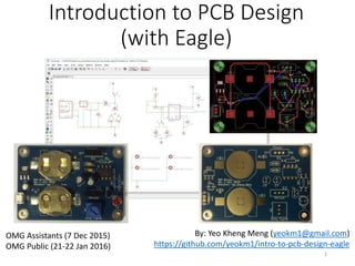
  • 1. Introduction to PCB Design (with Eagle) By: Yeo Kheng Meng (yeokm1@gmail.com) https://github.com/yeokm1/intro-to-pcb-design-eagle OMG Assistants (7 Dec 2015) OMG Public (21-22 Jan 2016) 1
  • 2. About Me • Graduated from NUS Computer Science in 2015 • Engineer at med-tech startup Algo Access 2
  • 3. What is a PCB? • Printed Circuit Board • A printed circuit board (PCB) mechanically supports and electrically connects electronic components using conductive tracks, pads and other features etched from copper sheets laminated onto a non-conductive substrate. • Wikipedia • Layman definition: • A board that lets you attach components to make a circuit. 3
  • 4. Before the PCB Source: https://cdn.sparkfun.com/r/700-700/assets/1/3/b/5/8/50cba0dcce395fb716000000.jpg Source: http://bunniefoo.com/novena/pvt2_release/novena_pvt2_top_sm.jpg Point to point wire wrapping vs Modern PCB of Novena laptop 4
  • 5. Motivation for makers? • Space and weight constraints • Making multiple copies of a design • Reduce mistakes in manual wiring/soldering • Aesthetics • Durability 5
  • 6. Objective of lesson Fundamental knowledge to • Understand PCB concepts • Design a PCB • Send for manufacturing • Properly share your design with others • Efficient SMD assembling techniques 6
  • 7. Structure of a 1-layer PCB board • Usually 1.6mm thick – applies to 2-4 layers too • Silkscreen (usually white): • Ink text. Usually used to mark out components • Soldermask (usually green): • Prevent solder (paste) from flowing out of designated areas forming solder bridges • Made of lacquer polymer that is “solderphobic” • Protects copper layer from oxidation • Copper: • Contains the traces (wires) between components • Also contains a ground/power plane (to be explained later) • Substrate • Gives the PCB mechanical strength and rigidity • Usually made of FR-4, composite of fibreglass and epoxy resin Modified from: https://cdn.sparkfun.com/assets/3/f/c/b/c/50d0c95bce395fd321000000.png 7
  • 8. Structure of a (≥2) multi-layer PCB board • 2-layer board = 2 copper layers, 4-layer board = 4 copper layers, etc • 2-layer boards good enough for most use-cases • Silkscreen and soldermask on top and bottom only • Vias • Hole in PCB that electrically connects points between copper layers • 1. Blind (only for >2 layer board) • 2. Buried (only for >2 layer board) • 3. Through-hole Source: http://techdocs.altium.com/display/ADRR/PCB_Obj-Via((Via))_AD 8
  • 9. Electronic Design Automation (EDA) Software • Software that helps you design PCBs • Eagle • Commonly used by makers + Adafruit + Sparkfun • Extensive library support • User-interface so-so • “Lite” version supports max 2 copper layers, 100 x 80 mm board size • Not the best for high-speed designs • Multi-platform • Saved as XML (ASCII) files, great for version-control • Altium Designer • Industry standard • De-facto option for high-speed designs and complex PCBs • Circuit simulation • User-interface is unrivaled IMO • File saved as binary format, terrible for version-control • Windows-only • Expensive: US$10K/license • KiCad • Recently becoming more popular • Free & open-source with no limitations • Libraries not as common • Saves in ASCII files, great for version-control • Multi-platform 9
  • 10. Component packages • 2D physical dimension of a component • Determines number of solder pads/sizes • Common surface-mount packages • 2-pin passives (don’t rely on external power) • 0603 (0.063 inch × 0.031 inch), 0805 (0.079 in × 0.049 in), 1206 (0.126 inch × 0.063 inch), … • SOD-123 (Small outline diode) • MELF (Metal electrode leadless face) cylindrical SMT component • ≥ 3 pins Active Components (rely on external power) • SOT23, SOT-223-4 (Small Outline Transistor: 2.2mm pitch, 3 pins front, 4 pins total), … • Integrated circuits (ICs), usually dual-inline or square • SOIC-16 (Small Outline Integrated Circuit 16 pins) • SSOP-28 (Shrink small outline package 28 pins) • TQFP-32 (Thin Quad Flat Package 32 pins) • QFN-48 (Quad Flat No leads 48 pins) • Others • Ports like USB, audio, • Board to board connectors like DF40C(2.0)-70DS-0.4V • Pin headers • uFL antenna connector 10https://github.com/yeokm1/open-source-pcb-ruler https://github.com/hemalchevli/Open-Source-PCB-Ruler
  • 11. PCB Design/Manufacturing Workflow 1. Establish project requirements 2. Acquire parts and prototype 3. Design your PCB schematic 4. Run electrical rule check (ERC). 5. Design board: place parts & wiring 6. Setup/run design rule check (DRC) 7. Do 3D rendering 8. Use CAM file to generate Gerbers 9. Zip up relevant Gerber files 10. Set PCB fabrication settings 11. Write out bill of materials (BOM) 12. PCB Assembly 11
  • 12. 1. Establish project requirements 1. Establish project requirements 2. Acquire parts and prototype 3. Design your PCB schematic 4. Run electrical rule check (ERC). 5. Design board: place parts & wiring 6. Setup/run design rule check (DRC) 7. Do 3D rendering 8. Use CAM file to generate Gerbers 9. Zip up relevant Gerber files 10. Set PCB fabrication settings 11. Write out bill of materials (BOM) 12. PCB Assembly • Circuit that blinks an LED • Customisable blink period • Customisable blink cycle • Run on CR2032 coin cells • Can run off USB power • Power switch 12
  • 13. 2. Acquire parts and prototype 1. Establish project requirements 2. Acquire parts and prototype 3. Design your PCB schematic 4. Run electrical rule check (ERC). 5. Design board: place parts & wiring 6. Setup/run design rule check (DRC) 7. Do 3D rendering 8. Use CAM file to generate Gerbers 9. Zip up relevant Gerber files 10. Set PCB fabrication settings 11. Write out bill of materials (BOM) 12. PCB Assembly • Consult data sheets to understand part selection choices • Logic Components • Texas Instruments TLC555 timer • Switch (C1 selection) • C1: 33uF/100uF capacitor • R1: 4.7kohm resistor • R2: 10k potentiometer • 2x 0.1uF decouple capacitors • Required according to TLC555 data sheet • Output components • 5mm 20mA Red LED • 100ohm current limiting resistor for LED • ON Semiconductor P2N2222A NPN Transistor • 1k ohm base resistor • Power components • 2x CR2032 battery holders • Micro-USB female connector • 3.3V low-dropout TC1262 regulator • Diodes for battery protection • 1uF output decouple capacitor • Required according to TC1262 datasheet • Switch to ON/OFF circuit *Quantity of 1 unless otherwise stated Reference: http://www.circuitbasics.com/555-timer-basics-astable-mode/ TLC555 cannot source high currents so we use a transistor to control the LED. 13
  • 14. 3a. Design your PCB Schematic 1. Establish project requirements 2. Acquire parts and prototype 3. Design your PCB schematic 4. Run electrical rule check (ERC). 5. Design board: place parts & wiring 6. Setup/run design rule check (DRC) 7. Do 3D rendering 8. Use CAM file to generate Gerbers 9. Zip up relevant Gerber files 10. Set PCB fabrication settings 11. Write out bill of materials (BOM) 12. PCB Assembly • Schematic defines connections between components 1. Open Eagle and add external libraries 2. Import libraries. • Locate the libraries folder I have provided • Drag-and-drop the *.lbr files one by one into Eagle Control Panel Libraries folder • Right-Click on Libraries Folder -> Use all 14
  • 15. 3b. Design your PCB Schematic 1. Establish project requirements 2. Acquire parts and prototype 3. Design your PCB schematic 4. Run electrical rule check (ERC). 5. Design board: place parts & wiring 6. Setup/run design rule check (DRC) 7. Do 3D rendering 8. Use CAM file to generate Gerbers 9. Zip up relevant Gerber files 10. Set PCB fabrication settings 11. Write out bill of materials (BOM) 12. PCB Assembly • Create and save schematic file (part and connection layout) • Create a folder on desktop “blinker” • Create new schematic *.sch: File -> New -> Schematic • Save schematic 15
  • 16. 3c. Design your PCB Schematic 1. Establish project requirements 2. Acquire parts and prototype 3. Design your PCB schematic 4. Run electrical rule check (ERC). 5. Design board: place parts & wiring 6. Setup/run design rule check (DRC) 7. Do 3D rendering 8. Use CAM file to generate Gerbers 9. Zip up relevant Gerber files 10. Set PCB fabrication settings 11. Write out bill of materials (BOM) 12. PCB Assembly • Add all Power components first • Micro-USB female connector • Seeed-OPL-Connector -> MICRO-USB-SMD(ZX62-B-5PA) • Or search 320010005 obtained via Seeedstudio OPL website • http://www.seeedstudio.com/depot/OPLopen-parts-library-catalog-c- 136_138/ • 3.3V LDO • bt_regulator -> TC1262 -> SOT-223-3 • 1uF decoupling resistor • rcl- > CPOL-US -> CPOL-USUD-4X5,8 • 2x Diodes • Seeed-OPL-Diode -> SMD-DIODE-SCHOTTKY-20V-500MA(SOD-123) • Or search 304020028 • 2x CR2032 battery holders • cr2032-large-side -> CR2032SMT • Through-hole switch • Sparkfun-Electromechanical -> SWITCH_SPDT -> SWITCH-SPDTPTH • VCC and GND wiring net • Just search for them… • There are 2 functionally identical supply1 and supply2 options for VCC and GND, just pick any one you prefer. 16
  • 17. 3d. Design your PCB Schematic 1. Establish project requirements 2. Acquire parts and prototype 3. Design your PCB schematic 4. Run electrical rule check (ERC). 5. Design board: place parts & wiring 6. Setup/run design rule check (DRC) 7. Do 3D rendering 8. Use CAM file to generate Gerbers 9. Zip up relevant Gerber files 10. Set PCB fabrication settings 11. Write out bill of materials (BOM) 12. PCB Assembly • Maneuvering and layout • Zoom with scroll-wheel • Click-drag middle mouse button to move sheet • Rotate components • Choose Move command • Click component “+” sign then right-click • Define component value if needed • Right-click component -> Value • Delete object with trash icon • Wiring • Use “Net” command • Link components together • Hover mouse just overlapping the contacts • Press “Alt” increased precision key if wire cannot overlap • Left-click to set and also to change direction 17
  • 18. 3e. Design your PCB Schematic 1. Establish project requirements 2. Acquire parts and prototype 3. Design your PCB schematic 4. Run electrical rule check (ERC). 5. Design board: place parts & wiring 6. Setup/run design rule check (DRC) 7. Do 3D rendering 8. Use CAM file to generate Gerbers 9. Zip up relevant Gerber files 10. Set PCB fabrication settings 11. Write out bill of materials (BOM) 12. PCB Assembly • Add and wire Logic Components • Ignore TIMER_OUTPUT • TLC555 timer (dual in-line package) • st-microelectronics -> NE555 • Not exact component but good enough • 4.7kohm axial resistor • resistor -> R-US_ -> R-US_0207/10 • 2mm diameter, 7mm length, 10mm lead length • 10kohm potentiometer • Sparkfun-Electromechanical -> TRIMPOT -> TRIMPOT-PTH-KNOB • Through-hole switch • Sparkfun-Electromechanical -> SWITCH_SPDT -> SWITCH-SPDTPTH • 33uF and 100uF aluminum electrolytic ”can” capacitors • resistor -> CPOL-US -> CPOL-USE2-5 • 2mm lead spacing, 5mm diameter, polarised • 2x 0.1uF ceramic decoupling capacitors • resistor -> C-US -> C-US025-025X050 • 2.5mm x 5mm area • VCC and GND • Just search for them… 18
  • 19. 3f. Design your PCB Schematic 1. Establish project requirements 2. Acquire parts and prototype 3. Design your PCB schematic 4. Run electrical rule check (ERC). 5. Design board: place parts & wiring 6. Setup/run design rule check (DRC) 7. Do 3D rendering 8. Use CAM file to generate Gerbers 9. Zip up relevant Gerber files 10. Set PCB fabrication settings 11. Write out bill of materials (BOM) 12. PCB Assembly • Expected result of Logic circuitry • Ignore “TIMER_OUTPUT” for now 19
  • 20. 3g. Design your PCB Schematic 1. Establish project requirements 2. Acquire parts and prototype 3. Design your PCB schematic 4. Run electrical rule check (ERC). 5. Design board: place parts & wiring 6. Setup/run design rule check (DRC) 7. Do 3D rendering 8. Use CAM file to generate Gerbers 9. Zip up relevant Gerber files 10. Set PCB fabrication settings 11. Write out bill of materials (BOM) 12. PCB Assembly • Add and wire Output Components • Ignore “TIMER_OUTPUT” for now • 100ohm and 1kohm axial resistor • resistor -> R-US_ -> R-US_0207/10 • 2mm diameter, 7mm length, 10mm lead length • 5mm Red LED • led -> LED -> LED5MM • ON Semiconductor P2N2222A NPN Transistor (TO92 package) • transistor -> 2N3565 • Not exact component but good enough • VCC and GND • Just search for them… 20
  • 21. 3h. Design your PCB Schematic 1. Establish project requirements 2. Acquire parts and prototype 3. Design your PCB schematic 4. Run electrical rule check (ERC). 5. Design board: place parts & wiring 6. Setup/run design rule check (DRC) 7. Do 3D rendering 8. Use CAM file to generate Gerbers 9. Zip up relevant Gerber files 10. Set PCB fabrication settings 11. Write out bill of materials (BOM) 12. PCB Assembly • Wiring nets • Connects between two “regions” • VCC and GND are Eagle’s provided wiring nets • We now connect logic circuit to the output circuit via TIMER_OUTPUT • Steps 1. Extend a short dummy wire on one side 2. Right click, choose “Label” 3. Position “N$” label just beside wire 4. Rename to something easier like “TIMER_OUTPUT” 5. Repeat for the other end Our custom net 21
  • 22. 3i. Design your PCB Schematic 1. Establish project requirements 2. Acquire parts and prototype 3. Design your PCB schematic 4. Run electrical rule check (ERC). 5. Design board: place parts & wiring 6. Setup/run design rule check (DRC) 7. Do 3D rendering 8. Use CAM file to generate Gerbers 9. Zip up relevant Gerber files 10. Set PCB fabrication settings 12. PCB Assembly • (Grounded) Mounting holes • Allows your PCB to be secured to external case • Grounded by screws. • Can also use normal ungrounded mounting holes • Appears in schematic as it is an electrical connection • Mounting hole • Grounded: • holes -> MOUNT-PAD-ROUND -> MOUNT-PAD-ROUND3.2 • Ungrounded: • holes -> MOUNT-HOLE -> MOUNT-HOLE3.2 • 3.2mm hole fits M3 screws with slight allowance 11. Write out bill of materials (BOM) 22
  • 23. 4. Run electrical check (ERC) 1. Establish project requirements 2. Acquire parts and prototype 3. Design your PCB schematic 4. Run electrical rule check (ERC). 5. Design board: place parts & wiring 6. Setup/run design rule check (DRC) 7. Do 3D rendering 8. Use CAM file to generate Gerbers 9. Zip up relevant Gerber files 10. Set PCB fabrication settings 11. Write out bill of materials (BOM) 12. PCB Assembly • Tests if your wiring has been done properly • Not foolproof but usually good enough to detect weird or missing connections • Run ERC regularly, assign to shortcut key. Options -> Assign • Correct ALL errors • Inspect all warnings • Correct if needed • Ignore if you are sure • I discourage approving 23
  • 24. 5a. Design board: place parts & wiring 1. Establish project requirements 2. Acquire parts and prototype 3. Design your PCB schematic 4. Run electrical rule check (ERC). 5. Design board: place parts & wiring 6. Setup/run design rule check (DRC) 7. Do 3D rendering 8. Use CAM file to generate Gerbers 9. Zip up relevant Gerber files 10. Set PCB fabrication settings 11. Write out bill of materials (BOM) 12. PCB Assembly • Create and save board file (board layout) • File -> Switch to board • Initial board configuration 1. Adjust grid settings to mm as shown. • View -> Grid 2. Create keyboard shortcuts for commonly used functions. • Options -> Assign • Not case-sensitive • End with “;” 3. Enable Vector font 1. Options -> User Interface 2. Tick Always vector font 3. Tick Persistent CAM Processor can only convert vector fonts into Gerbers properly. See: http://www.cadsoft usa.com/training- service/faq/#c95 24
  • 25. 6a. Setup/run design rule check (DRC) 1. Establish project requirements 2. Acquire parts and prototype 3. Design your PCB schematic 4. Run electrical rule check (ERC). 5. Design board: place parts & wiring 6. Setup/run design rule check (DRC) 7. Do 3D rendering 8. Use CAM file to generate Gerbers 9. Zip up relevant Gerber files 10. Set PCB fabrication settings 11. Write out bill of materials (BOM) 12. PCB Assembly • Design rules provided by fabricator to check if your PCB adheres to requirements • Download PCB fabricator DRU, in this case Elecrow • http://www.elecrow.com/10pcs-2-layer-pcb-p-1175.html • http://www.elecrow.com/download/Elecrow_PCB_eagle_rule.zip *I use Elecrow as a learning example here but it does not mean I endorse this company in any way. 25
  • 26. 6b. Setup/run design rule check (DRC) 1. Establish project requirements 2. Acquire parts and prototype 3. Design your PCB schematic 4. Run electrical rule check (ERC). 5. Design board: place parts & wiring 6. Setup/run design rule check (DRC) 7. Do 3D rendering 8. Use CAM file to generate Gerbers 9. Zip up relevant Gerber files 10. Set PCB fabrication settings 11. Write out bill of materials (BOM) 12. PCB Assembly • Load DRU file just once • Press “check” to check your board or use keyboard shortcut • Rectify all errors 26
  • 27. 5b. Design board: place parts & wiring 1. Establish project requirements 2. Acquire parts and prototype 3. Design your PCB schematic 4. Run electrical rule check (ERC). 5. Design board: place parts & wiring 6. Setup/run design rule check (DRC) 7. Do 3D rendering 8. Use CAM file to generate Gerbers 9. Zip up relevant Gerber files 10. Set PCB fabrication settings 11. Write out bill of materials (BOM) 12. PCB Assembly • General board steps 1. Adjust board size to your requirements eg: 99mm x 49mm (check fabricator price point) 2. Place ground/power plane on Top layer using polygon function. 1mm away from edges to ease future resizing. Set polygon name. 27
  • 28. 5c. Design board: place parts & wiring 1. Establish project requirements 2. Acquire parts and prototype 3. Design your PCB schematic 4. Run electrical rule check (ERC). 5. Design board: place parts & wiring 6. Setup/run design rule check (DRC) 7. Do 3D rendering 8. Use CAM file to generate Gerbers 9. Zip up relevant Gerber files 10. Set PCB fabrication settings 11. Write out bill of materials (BOM) 12. PCB Assembly • General board steps 3. Component placement order 1. Place mounting holes 2. User-facing components, like USB connectors, switches and LEDs 3. Large components 4. Everything else 4. Wiring order (Trace width usually the size of the solder pads) 1. Wire high-speed connections, avoid using vias 2. Wire power connections with wider traces 3. Wire everything else 5. Execute DRC check and rectify if needed 6. Silkscreen placement order (don’t overlap with any holes/vias/parts) 1. Smash component & adjust part designators if required to minimise confusion 2. Add descriptive text to certain areas to silkscreen 3. Add PCB description/revision 7. Miter corners 8. Make sure Ratsnest gives “Nothing to do” • Tips • Execute Ratsnest to recalculate remaining airwires’ position as much as possible after every operation • Run DRC after you make every change to catch problems earlier • Wire at 45 degree angles to reduce signal reflection 28
  • 29. 7. Do 3D rendering 1. Establish project requirements 2. Acquire parts and prototype 3. Design your PCB schematic 4. Run electrical rule check (ERC). 5. Design board: place parts & wiring 6. Setup/run design rule check (DRC) 7. Do 3D rendering 8. Use CAM file to generate Gerbers 9. Zip up relevant Gerber files 10. Set PCB fabrication settings 11. Write out bill of materials (BOM) 12. PCB Assembly • Use this website http://3dbrdviewer.cytec.bg/ • Check for any visible errors, especially silkscreen overlap • Check for components’ “closeness”. • Go back to Step 5 if not satisfied 29
  • 30. 8. Use CAM file to generate Gerbers 1. Establish project requirements 2. Acquire parts and prototype 3. Design your PCB schematic 4. Run electrical rule check (ERC). 5. Design board: place parts & wiring 6. Setup/run design rule check (DRC) 7. Do 3D rendering 8. Use CAM file to generate Gerbers 9. Zip up relevant Gerber files 10. Set PCB fabrication settings 11. Write out bill of materials (BOM) 12. PCB Assembly • Gerber files • 2D vector format used by PCB fabricator to make PCBs for you • CAM file provided by fabricator to help you generate Gerber layer files • Download PCB fabricator’s CAM processor, in this case Elecrow • http://www.elecrow.com/10pcs-2-layer-pcb-p-1175.html • http://www.elecrow.com/download/Elecrow_Gerber_Generater_Drill Align.zip • Use the correct CAM file according to number of layers like 2 layers • Open CAM Processor: File -> CAM Processor • Once in CAM Processor, load the CAM job as shown below • Once you are done, click “Process Job” 30
  • 31. 9. Zip up relevant Gerber files 1. Establish project requirements 2. Acquire parts and prototype 3. Design your PCB schematic 4. Run electrical rule check (ERC). 5. Design board: place parts & wiring 6. Setup/run design rule check (DRC) 7. Do 3D rendering 8. Use CAM file to generate Gerbers 9. Zip up relevant Gerber files 10. Set PCB fabrication settings 11. Write out bill of materials (BOM) 12. PCB Assembly • See what files are required by the PCB fabricator • Elecrow’s requirements: • Go to saved folder and zip up the required files • Rightfully you should inspect your Gerber files for potential mistakes using software/websites like: • GR-Prevue: http://www.graphicode.com/GC-Prevue_Gerber_Viewer • http://circuitpeople.com/ • http://mayhewlabs.com/webGerber/ • But so far I don’t have any problems so I usually skip the Gerber file check step 31
  • 32. 10a. Set PCB fabrication settings 1. Establish project requirements 2. Acquire parts and prototype 3. Design your PCB schematic 4. Run electrical rule check (ERC). 5. Design board: place parts & wiring 6. Setup/run design rule check (DRC) 7. Do 3D rendering 8. Use CAM file to generate Gerbers 9. Zip up relevant Gerber files 10. Set PCB fabrication settings 11. Write out bill of materials (BOM) 12. PCB Assembly • Go to order page http://www.elecrow.com/10pcs-2-layer-pcb-p-1175.html • Basic options like PCB size, color and lead time self explanatory 32
  • 33. 10b. Set PCB fabrication settings 1. Establish project requirements 2. Acquire parts and prototype 3. Design your PCB schematic 4. Run electrical rule check (ERC). 5. Design board: place parts & wiring 6. Setup/run design rule check (DRC) 7. Do 3D rendering 8. Use CAM file to generate Gerbers 9. Zip up relevant Gerber files 10. Set PCB fabrication settings 11. Write out bill of materials (BOM) 12. PCB Assembly • Layer • 1-layer with mask both side: 1 copper layer only but you want both sides soldermask/silkscreen • 1-layer with mask one side: 1 copper layer only and you want one side soldermask/silkscreen • 2-layer: normal two copper layer boards • Copper weight: • Copper layer thickness and amount, 1oz is usually enough • PCB Thickness: • Typical is 1.6mm • Elecrow can go as thin as 0.6mm for normal FR4 PCBs. Flex PCBs can go even thinner like 0.1mm • Surface finish • HASL vs ENIG next slide • PCB Stencil • Help you solder SMT components if you have solder paste and reflow oven/hotplate • Frame or no frame provided. I normally go with the frame as it just costs slightly more. • Panelizing • Squeeze many small PCBs into one piece to save space but you have to cut after receiving. • I normally pick “Single PCB with milling” as I have no need to panelize my PCB 33
  • 34. 10c. Set PCB fabrication settings 1. Establish project requirements 2. Acquire parts and prototype 3. Design your PCB schematic 4. Run electrical rule check (ERC). 5. Design board: place parts & wiring 6. Setup/run design rule check (DRC) 7. Do 3D rendering 8. Use CAM file to generate Gerbers 9. Zip up relevant Gerber files 10. Set PCB fabrication settings 11. Write out bill of materials (BOM) 12. PCB Assembly • Others: • Electrolytic Gold-plating, Immersion Silver, Immersion Tin, Organic Surface Protectant HASL vs ENIG 34 HASL (lead-free) ENIG Acronym for Hot Air Solder Levelling Electroless nickel immersion gold How it is made? Copper surfaces covered with solder by dipping PCB in solder then blowing away Copper surfaces covered with nickel with gold coating via immersion Coating evenness Uneven, don’t use for fine- pitch SMD components Very even coat, must use if you have fine SMD components. Durability Reasonable, but don’t expose too long to air Better than HASL, can last for months Solderability (should not factor in your decision) Great So-so Cost Low High
  • 35. 11. Write out bill of materials (BOM) 1. Establish project requirements 2. Acquire parts and prototype 3. Design your PCB schematic 4. Run electrical rule check (ERC). 5. Design board: place parts & wiring 6. Setup/run design rule check (DRC) 7. Do 3D rendering 8. Use CAM file to generate Gerbers 9. Zip up relevant Gerber files 10. Set PCB fabrication settings 11. Write out bill of materials (BOM) 12. PCB Assembly • Export BOM and modify. • So others can replicate your PCB • Go to Schematic view, File -> Export -> BOM • Select Parts type and CSV format as shown • Use Libreoffice to open CSV file and save in its native ODS format • CSV not enough features, does not store column width • Some Excel versions have difficulty opening CSV file generated by Eagle • Open-source format • Modifying the generated BOM 1. Remove mounting holes 2. Collapse duplicate devices and combine their part designators 3. Remove: Description, OC_FARNELL, OC_NEWARK, PROD_ID, last VALUE column 4. Add: Quantity, Unit Cost , Total Unit cost (=Quantity * Unit Cost), Source webpage 5. Modify the generic Eagle BOM with the actual BOM data (also add PCB Fab cost) 6. Can have final Total Cost at bottom if you wish 35
  • 36. 12a. PCB Assembly 1. Establish project requirements 2. Acquire parts and prototype 3. Design your PCB schematic 4. Run electrical rule check (ERC). 5. Design board: place parts & wiring 6. Setup/run design rule check (DRC) 7. Do 3D rendering 8. Use CAM file to generate Gerbers 9. Zip up relevant Gerber files 10. Set PCB fabrication settings 11. Write out bill of materials (BOM) 12. PCB Assembly • Manual Soldering • Soldering station • Through-hole and SMT components • Specialised SMD Soldering techniques (with stencil and paste) • Hot air blower • Hot plate • Reflow oven 36
  • 37. 12b. PCB Assembly 1. Establish project requirements 2. Acquire parts and prototype 3. Design your PCB schematic 4. Run electrical rule check (ERC). 5. Design board: place parts & wiring 6. Setup/run design rule check (DRC) 7. Do 3D rendering 8. Use CAM file to generate Gerbers 9. Zip up relevant Gerber files 10. Set PCB fabrication settings 11. Write out bill of materials (BOM) 12. PCB Assembly • Reflow Soldering only for surface-mount components • Requires stencil and solder paste • FIRST stencil/reflow the SMD components THEN solder the through-hole components by hand. • A typical thermal profile, consult data sheet to determine optimum profile • Thermal profile based on: • Lead vs lead-free solder paste • Lead vs lead-free components • Lead vs lead-free use depends on RoHS compliance • Profile Steps 1. Preheat: Flux activation 2. Soak: Ensure all board and components are at the same temperature 3. Reflow: “Melts” solder paste and let it settle properly on the solder pads 4. Cooling: Brings temperature back down at controlled rate to prevent thermal stress Source: http://www.compuphase.com/electronics/reflowsolderprofiles.htm 37
  • 38. DIY PCB Fabrication (Toner transfer) • Materials • Liquid Mixture: Vineger, Table Salt, Hydrogen Peroxide (H202) • Transfer paper • FR-4 board • Steps 1. Print circuit diagram on transfer paper using laser printer 2. Iron/Heat press transfer paper into FR-4 board • https://www.youtube.com/watch?v=dvLRrXjktbE 3. Mix liquid mixture of vinegar, H202 and salt 4. Submerge FR-4 board in liquid mixture and agitate 5. Continue until all exposed copper has been “eaten away”. (Toner covers areas you want to leave behind) 6. Use a solvent/paint thinner to wipe off the toner 7. Drill holes to create vias 38 Source, Leon Lim: http://gylim78.blogspot.sg/2014/07/the-diy-pcb-making-guide.html http://gylim78.blogspot.sg/2015/05/pcb-board-gallery.html Export DIY PCB images from Eagle: http://yeokhengmeng.com/2016/03/eagle-file-to-diy-pcb-etching/
  • 39. Time to design your own board! 39
  • 40. Final Words • This is just the beginning • Practice makes perfect, the more PCBs you design/fabricate, the better you will get • Unlikely to get right on the first fabrication attempt • 2-3 times or more per design 40