Manual de Recarga Samsung CLP 600 CLP 650
•
0 likes•464 views

The document provides technical instructions for replacing components in the Samsung CLP-600 printer. It describes 20 steps for taking the printer cartridge apart and cleaning or replacing parts like the drum, developer roller, gears, and chip. Photos accompany each step to illustrate the process. The instructions are intended to guide replacement of parts with non-OEM alternatives supplied by Future Graphics.

Recommended
More Related Content
What's hot
What's hot (20)
Viewers also liked
Viewers also liked (14)
Similar to Manual de Recarga Samsung CLP 600 CLP 650
Similar to Manual de Recarga Samsung CLP 600 CLP 650 (19)
More from Valejet
More from Valejet (14)
Recently uploaded
Recently uploaded (20)
Manual de Recarga Samsung CLP 600 CLP 650
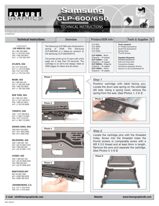
- 1. CLP600TECH Technical Instructions Overview Printers/OEM Info Tools & Supplies 1 CLP-600 Tools required: CORPORATE The Samsung CLP-600 was introduced in CLP-600N #1 Phillips Screwdriver LOS ANGELES, USA spring of 2006. The Samsung CLP-650 Small Flat Screwdriver US 1 800 394.9900 CLP-600/650 is a follow-on product to CLP-650N Spring Hook Int’l +1 818 837.8100 the Samsung CLP-500/550/510. Thumb Screws FAX 1 800 394.9910 CLP-K600A – Black Int’l +1 818 838.7047 (Capacity – 4K pages) Supplies Required: The printer prints up to 21 ppm with a first CLP-C600A – Cyan DRUMPOWDERCPT page out in less than 20 seconds. The (Capacity – 4K pages) Soft Lint-Free Cloth ATLANTA, USA cartridge is an all-in-one design rated at CLP-M600A – Magenta Conductive Grease US 1 877 676.4223 4000 pages for black and all colors. (Capacity – 4K pages) Anhydrous Isopropyl Alcohol Int’l +1 770 516.9488 CLP-Y600A – Yellow Vacuum or dry Compressed Air FAX 1 877 337.7976 (Capacity – 4K pages) Int’l +1 770 516.7794 Photo 1 MIAMI, USA Step 1 US 1 800 595.429 Int’l +1 305 594.3396 Position cartridge with label facing you. FAX 1 800 522.8640 Locate the drum axle spring on the cartridge Int’l +1 305 594.3309 left side. Using a spring hook, remove the spring from the axle. (See Photos 1, 2 & 3) NEW YORK, USA US 1 800 431.7884 Photo 3 Int’l +1 631 345.0121 FAX 1 800 431.8812 Photo 2 Int’l +1 631345.0690 TORONTO, CAN CAN 1 877 848.0818 Int’l +1 905 712.9501 FAX 1 877 772.6773 Int’l +1 905 712.9502 BUENOS AIRES, ARG ARG 0810 444.2656 Photo 4 Int’l +011 4583.5900 Step 2 FAX +011 4584.3100 Locate the cartridge pins with the threaded holes. Screw into the threaded holes the MELBOURNE, AUS thumb screws or comparable screw with a AUS 1 800 003. 100 Int’l +62 03 9561.8102 M3 X 0.5 thread and at least 8mm in length. FAX 1 800 004.302 Remove the pins and separate the cartridge. Int’l +62 03 9561-7751 (See Photos 4, 5 & 6) SYDNEY, AUS Photo 6 AUS 1 800 003.100 Int’l +62 02 9648.2630 FAX 1800 004.302 Photo 5 Int’l +62 02 9548.2635 MONTEVIDEO,URY URY 02 902.7206 Int’l +5982 900.8358 FAX +5982 908.3816 JOHANNESBURG, S.A. S.A. +27 11 974.6155 FAX +27 11 974.3593 E-mail: info@futuregraphicsllc.com Website: www.futuregraphicsllc.com REV: 6/04/07
- 2. 2 Samsung CLP600 Technical Instructions Photo 10 Step 5 Remove the drum axle pushing the axial Step 3 towards the gear side of the drum. After separating the cartridge, Remove the drum and set aside in a light- put aside the toner unit. protected area. (See Photo 7) (See Photo 10) Photo 11 Photo 7 Step 6 Remove PCR from saddle blocks. Set PCR aside. (See Photo 11) Photo 12 Step 7 Remove the screws to the wiper blade Step 4 and remove wiper blade. Clean waste Position the waste unit with the toner area using a vacuum or dry, drum closest to you. Remove compressed air. the two E clips on each end of (See Photo 12) the drum axle. (See Photos 8 & 9) Photo 13 Step 8 Photo 8 Clean wiper blade with a soft, dry cloth or dry, compressed air. Apply padding pow- der DRUMPOWDERCPT to the blade edge and reinstall wiper blade. (See Photos 13 & 14) Photo 14 Photo 9 Step 9 Clean PCR saddle blocks and PCR con- tact with cotton swab and Anhydrous Isopropyl Alcohol. Clean PCR using a dry, soft, lint-free cloth. NOTE: If needed, deionized water can be used to clean the PCR. Photo 15 (See Photos 15 & 16) Photo 16
- 3. Samsung CLP600 Technical Instructions 3 Photo 17 Step 10 Apply conductive grease to the PCR con- tact. Install PCR into saddle blocks. Step 15 (See Photos 17 & 18) Remove the two screws holding the drive gear cover. Remove Photo 18 drive gear cover. Remove the four lower gears. Remove screw for gear assembly. Remove gear assembly. (Sees Photos 25, 26 & 27) Photo 19 Photo 25 Step 11 Clean drum using soft, dry cloth. Apply padding powder DRUMPOWDERCPT to Photo 20 the drum. (See Photos 19 & 20) Photo 26 Step 12 Position drum in the waste unit. Insert Photo 21 rounded end of drum axle into the non- gear side of the drum. Spin axle and be careful not to damage the drum contacts. Install E clips onto drum axle. (See Photos 21 & 22) Step 13 Set aside the waste unit. Protect the drum from light exposure. Photo 22 Photo 27 Step 14 Starting on the toner unit, remove the two screws holding the contacts cover. Remove the left side developer roller end cap by separating end cap from cartridge using a flat screwdriver. (See Photos 23 & 24) Photo 23 Photo 24
- 4. 4 Samsung CLP600 Technical Instructions Photo 31 Step 17 Install developer roller spacers and drum Step 16 bearings. Install developer roller into car- Remove the developer roller. tridge. Insure that spacers are flush up Remove drum bearings and against the developer roller. spacers. Clean excess toner by (See Photos 31 & 32) blowing dry, compressed air over the developer roller. Finish with a hand wipe using a dry, Photo 32 soft, lint-free cloth on the devel- oper roller, drum bearings, and spacers. (See Photos 28, 29 & 30) Photo 28 Photo 33 Step 18 Install gear assembly using the one screw. Install the four gears. (See Photos 33 & 34) Photo 29 Photo 34 Photo 30 Photo 35 Step 19 Install gear cover using the two screws. (See Photo 35) Photo 36 Step 20 Install developer roller end cap. (See Photo 36)
- 5. Samsung CLP600 Technical Instructions 5 Photo 37 Step 21 Clean the contacts in the contact cover. Apply contact grease to the developer roller and supply roller contacts. Reinstall Step 24 cover using the two screws. Place the toner and waste units (See Photos 37, 38 & 39) together and install cartridge pins. The long pin goes to the gear side and the short pin is used in the contact side. Photo 38 Remove thumb screws from the cartridge pins. Install drum axle spring. (Sees Photos 43 & 44) Photo 43 Photo 39 Photo 40 Step 22 Remove fill plug, fill with toner, and Photo 44 replace fill plug. Check for leaks. (See Photos 40 & 41) Photo 41 Photo 42 Step 23 Returning to the waste unit, locate the chip mounted in the back of the cartridge. To remove the chip, gently push the chip Future Graphics (FG) is a distributor of com- out of the holding area while lifting the patible replacement parts and products for plastic bar. Replace OEM chip with after- imagining equipment. None of FG's products are genuine OEM replacement parts and no market chip. (See Photo 42) affiliation or sponsorship is to be implied between FG and any OEM.