
Recommended
More Related Content
What's hot
What's hot (20)
Viewers also liked
Viewers also liked (20)
Similar to Cable terminations
Similar to Cable terminations (20)
Recently uploaded
Recently uploaded (20)
Cable terminations
- 1. Cable Terminations and Joints
- 2. Wire cutters
- 4. Crimping tools • Colour coded like crimps • Better quality auto release at correct pressure
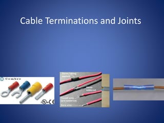
- 5. Crimps • Used to terminate the end of cables. • Used as they enter control panels, starters etc. • Small crimps. Colour denotes cable size. • Can be used to join cables • Various quality of tools available
- 6. Power cable crimps • Hydraulic tools used to compress large crimps • Essential correct size crimp and Die used • Poor connection will create excessive heat and potential fire.
- 7. Soldering Irons • Gas or electric • Various wattages • Tip to be kept clean(Wet sponge)
- 8. Soldered joint • Strip cable insulation • Tin Wire • Join tinned wires using heat and solder • Insulate joint with heat shrink
- 9. Single core joint • Strip insulation from cable • Twist cables tightly together • Melt solder into the joint • Insulate with heat shrink
- 10. Heat shrink
- 11. QUESTIONS
Editor's Notes
- Q. What do we use them for. Used to terminate the end of cables to allow connection to other services or to join cables. Used as they enter control panels, starters etc. Small crimps colour denotes cable size. Cable to be as snug a fit in the crimp as possible. Correct tool required for size and colour of crimp. Q. What happens if connection between crimp and cable not sufficiently tight. Increases resistance, increased current, heat, damage, potential separation and failure.
- Variety available. Correct size for the job, Small side snips for removing excess component wire after soldering electronic components. Q. Hazard with large cutters. Injury possible to hands. Q. What is electrical cable made of. Copper (soft). What would happen to cutter blades of they are used to cut steel. Damage blades.
- Using wire strippers less likely to damage cable than using wire cutters. Variety of different types and costs available
- Correct section colour coded to crimp must be used. Correct diameter crimp bore must be used for cable cross sectional area. Exposed copper to extend full length of enclosed part of crimp. Q. ½ way through in line join. No un insulated stripped core to be exposed at either end. When using pins or rings align tool with inside of crimp. Heat shrink can be used to provide additional support.
- Used primarily on the end of control and instrumentation cables In line crimps can be used to conduct cable repair joint, or join 2 cables. Small terminations colour of crimp denotes size of cable. Red, Blue, yellow, increasing in size. Use the crimp that is the tightest fit the with the cable (Un-crimped) Various tools available. Better quality tools calibrated to provide correct compression of crimp prior to releasing. Cable insulation to be removed prior to insertion in crimps. Care required to remove correct length. Stripped cable to be fully inserted into crimp until they are flush with termination end.
- Larger crimps used on power cables Not insulated to enable greater compression of metal. Q Heat shrink can be used. Essential correct crimp size and tool die size used in order to get good connection What happens if connection to cable poor. (Increased resistance, heat and potential fire or damage) Thermographic survey can identify problems
- Q. What is the hazard. All capable of causing burns to people and surroundings. Use carefully and be aware where you are putting it. Different wattages available, sufficient heat required to heat the wire to solder melting point (220 C) Tip needs to be clean. Clean by wiping tip on a damp sponge. Re tin tip on completion. Flux in core helps solder run and adhere by cleaning surface. Avoid breathing in fumes produced when soldering.
- Used on multicore cable Essential to tin ends of both cables Lie tinned parts parallel and re heat to join Larger capacity soldering iron required than those used for electronics if joining larger cables (1mm square and above). (30W, 100W) Tinning multicore can be used in place of a pin crimp for the end of cables as they enter terminals Joints can be made by twisting cables together prior to the tinning stage. Various tools available to assist holding wires. Be aware if it’s in contact with the wire it will absorb heat.
- Can be used to provide a strong joint in single core cable. Make initial cross at shallow angle, before winding tightly at 90 degrees. Heat joint and melt solder until it runs. Can be insulated with heat shrink
- Insulation to cover bare cable. Shrinks when heat applied. Also adds support to the joint. Various sizes and colours available. Colour does not denote size. Use smallest size that will fit over joint prior to shrinking. Double layers can be used to improve support and insulation. Overlap 2nd layer with a longer piece.