The Hybrid Microcircuit Micromodule ; Solid Logic Technology Vintage Computer Chip, Semiconductor ; Transistor Memorabilia
•
0 likes•1,894 views

from web site ChipsEtc.com http://www.chipsetc.com/the-hybrid-microcircuit.html

Recommended
More Related Content
Viewers also liked
More from Tom Terlizzi
The Hybrid Microcircuit Micromodule ; Solid Logic Technology Vintage Computer Chip, Semiconductor ; Transistor Memorabilia
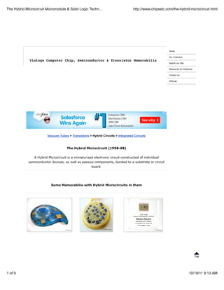
- 1. The Hybrid Microcircuit Micromodule & Solid Logic Techn... http://www.chipsetc.com/the-hybrid-microcircuit.html Home Our Collection Vintage Computer Chip, Semiconductor & Transistor Memorabilia Search our Site Resources for Collectors Contact Us Sitemap Vacuum Tubes > Transistors > Hybrid Circuits > Integrated Circuits The Hybrid Microcircuit (1958-68) A Hybrid Microcircuit is a miniaturized electronic circuit constructed of individual semiconductor devices, as well as passive components, bonded to a substrate or circuit board. Some Memorabilia with Hybrid Microcircuits in them 1 of 9 10/19/11 9:13 AM
- 2. The Hybrid Microcircuit Micromodule & Solid Logic Techn... http://www.chipsetc.com/the-hybrid-microcircuit.html Interconnecting Electronic Circuits - The birth of the Micro-Module Before the invention of the IC, electronic equipment was composed of discrete components like transistors, which serve as both switches and amplifiers; resistors, which impede the flow of electrons; and capacitors, which store them. These components, often simply called "Discretes", were manufactured separately and were wired or soldered together onto Masonite-like circuit boards. Discretes took up a lot of room and were expensive and cumbersome to assemble, so engineers began, in the mid-1950s, to search for a simpler approach. For almost 50 years after the turn of the 20th century, the electronics industry had been dominated by vacuum tube technology. But vacuum tubes had inherent limitations. They were fragile, bulky, unreliable, power hungry, and produced considerable heat. It wasn't until 1947, with the invention of the transistor by Bell Telephone Laboratories, that the vacuum tube problem was solved. Transistors were miniscule in comparison, more reliable, longer lasting, produced less heat, and consumed less power. The transistor stimulated engineers to design ever more complex electronic circuits and equipment containing hundreds or thousands of discrete components such as transistors, diodes, rectifiers and capacitors. But the problem was that these components still had to be interconnected to form electronic circuits, and hand-soldering thousands of components to thousands of bits of wire was expensive and time-consuming. It was also unreliable; every soldered joint was a potential source of trouble. The challenge was to find cost-effective, reliable ways of producing these components and interconnecting them... The Micro-Module (1958-1964) One stab at a solution was the Micro-Module (also know as a Micromodule) program, sponsored by the U.S. Army Signal Corps. The idea was to make all the components a uniform size and shape, with the 2 of 9 10/19/11 9:13 AM
- 3. The Hybrid Microcircuit Micromodule & Solid Logic Techn... http://www.chipsetc.com/the-hybrid-microcircuit.html wiring built into the components. The modules then could be snapped together to make circuits, eliminating the need for wiring the connections. The micromodule system called for piling tiny wafers of discretes on top of each other like dishes. Connecting wires ran up the sides of the stacks through holes in the wafers. Micromodules were not only somewhat easier to make than conventional electronic systems, they were also a good deal smaller: a six-component module was about the size of the sharpened cone of a pencil. In the summer of 1958, a young engineer by the name of Jack S. Kilby went to work for Texas Instruments, which by then had earned a reputation for itself as an innovative manufacturer of transistors. Kilby was slated to work on TI's micromodule program, but the army's system seemed to him to be unnecessarily complicated. He wondered whether it would be possible, instead of stacking discretes on top of each other, to fabricate all the electronic components - transistors, resistors, and the like - out of the same piece of material. It occurred to him that a properly engineered slice of germanium might be made to act as a whole slew of components, much as a tapestry can be embroidered with any RCA's Micro-Module number of designs and colors. As computer systems grew more complex, engineers sought simpler ways to interconnect the thousands of transistors they employed. Government agencies funded micro-module and multi-chip hybrid circuit projects in search of a solution to this problem. In 1952, G. W. A. Dummer of England's Telecommunications Research Establishment proposed "With the advent of the transistor and the work in semiconductors generally, it seems now possible to envisage electronic equipment in a solid block with no connecting wires." As computer systems grew more complex, engineers sought simpler ways to interconnect the thousands of transistors they employed. Government agencies funded micro-module and multi-chip hybrid circuit projects in search of a solution to this problem. A hybrid integrated circuit, HIC, hybrid microcircuit, or simply hybrid is a miniaturized electronic circuit constructed of individual devices, such as semiconductor devices (transistors & diodes) and passive components (resistors, inductors, transformers & capacitors), bonded to a substrate or printed circuit board (PCB). Hybrid circuits are often encapsulated in epoxy. A hybrid circuit serves as a component on a PCB in the same way as a monolithic integrated circuit; the difference between the two types of devices is in how they are constructed and manufactured. The advantage of hybrid circuits is that components which cannot be included in a monolithic IC can be used. MICROMODULES: THE ULTIMATE PACKAGE (Army research) Electronic Engineering Times, December 27, 1999, Rostky, George It looked like a fountain pen, albeit a fat one, but it was really a radio. The U.S. Army liked it, not just because it was very small for a radio, but because it introduced a new concept in circuit packaging —small size and uniform construction. RCA's Surface Communications Division showed this pen-size radio to the U.S. Army in October 1957, shortly after the Russians launched Sputnik, and demonstrated that the world's leader in technology, the Americans, were way behind. At a time when the American military was desperate to catch up, this ultimate in packaging density, called a micromodule, could be just the answer. The Army loved the concept. In April 1958, it awarded RCA a $5 million contract in what became known as the Micromodule Program. Just a few months later, in January 1959, RCA's Aerospace Communications and Controls Division built a stable inertial-guidance platform using micromodules. And just two months after that, in March, at the annual show and convention of the Institute of Radio Engineers (an IEEE predecessor), at a joint press conference with the Signal Corps, RCA announced the commercial availability of Micromodule Designer's Kits for breadboards. Then, in July 1959, the Army added $2.4 million to RCA's contracts—for new microelements, as they were called—and for higher-temperature capabilities for some elements. In February 1960, the Army added $8 million for demonstration helmet radios and miniature computers. 3 of 9 10/19/11 9:13 AM
- 4. The Hybrid Microcircuit Micromodule & Solid Logic Techn... http://www.chipsetc.com/the-hybrid-microcircuit.html The micromodule, as the package was called, was fundamentally akin to the short-lived Project Tinkertoy, which the Navy funded in 1951. Tinkertoys were based on using 5/8-inch-square ceramic wafers, each of them bearing a discrete component. That concept was the brainchild of Robert Henry at the National Bureau of Standards. The Micromodule Program was to use smaller ceramic wafers, 0.36-inch square, with three solder ridges along each edge. These squares were stacked and interconnected by riser wires soldered to those solder ridges, where appropriate. The entire module could be encapsulated and, depending on the circuitry involved, might be from 0.4- to 0.8-inch high. Modules could be designed for almost any system. Production of a wafer element could be automated. Individual microelements might contain almost any component. While RCA was the prime contractor, more than 60 producers participated in developing individual microelement components and wafers. And here was another advantage. Individual suppliers became component specialists and experts. Some companies would specialize in film capacitors; others would do aluminum or tantalum electrolytic capacitors; still others would offer thin-film or thick-film resistor networks; inductors; trimming potentiometers; and bare transistor chips (called "dot" transistors). The top-most wafer could support a socket for a miniature 7- or 9-pin vacuum tube, but that feature was never used, as transistors were already in widespread use. It was more than obvious that the micromodule was the circuit package for the future. It was more expensive than conventional printed-circuit packages, but follow-on costs, like maintenance and logistics (including storage, handling and training) were lower. The initial cost was indeed higher. In 1962, a 10-component micromodule cost $52 compared with $20.45 for a printed-circuit-board equivalent. But micromodule costs were expected to plummet with increased production in 1963 and 1964, with costs approaching or even slipping below conventional- package prices, and declining rapidly beyond that. Reliability soared. Based on millions of testing hours, RCA reported that the micromodule proved to be six times as reliable as conventional military circuits and 60 times as reliable as tube circuits, still widely used. Most wonderful, circuit density was beyond the wildest imagination of a few years earlier. RCA's helmet radio had the equivalent of 210,000 components per cubic foot. And the future might see packages with a staggering 600,000 parts per cubic foot. This was a remarkable contrast to 100,000 parts per cubic foot in the most advanced conventional circuitry. For once, the future was clear. In August 1962, the Army's chief signal officer, Major General Earle F. Cook, reported that the micromodule program had proved so successful that the Army's deputy chief of staff for logistics had issued a directive to "take prompt and positive action to incorporate the micromodule concept as appropriate." Cook reported that the Army expected to commit $8 million for micromodule equipment in fiscal 1963, about double the 1962 funding. Some $18 million had already been invested in the program. In his 1962 report—at a joint press conference with RCA—Cook looked back fondly at the March 1959 Signal Corps-plus-RCA press conference when the micromodule was introduced to the world with great expectations. As he listed a large number of micromodularized equipment that was to be purchased, Cook expounded on the great benefits already realized as a result of the micromodule revolution since that 1959 press conference. The Future Cook did note that the micromodule would accommodate advanced integrated circuitry, "logically, through evolution, rather than by revolution. Such developments," he said, "normally mature bit-by-bit over a protracted period of time, rather than suddenly appearing as an entire operational system. The industry anticipates a long period of applications of the new devices in hybrid combinations with conventional components." Cook was clearly aware that the "advanced integrated circuitry," which micromodules would accommodate through evolution over a protracted period of time, were beginning to attract some attention. But he may not have been aware of another press conference that took place in March 1959, possibly 4 of 9 10/19/11 9:13 AM
- 5. The Hybrid Microcircuit Micromodule & Solid Logic Techn... http://www.chipsetc.com/the-hybrid-microcircuit.html just a few doors from the Signal Corps-RCA press conference. That's when Texas Instruments announced the work of an engineer, Jack Kilby, who had joined the company a year earlier. Kilby had developed what TI called a "solid circuit," and what TI hailed as the ultimate in microminiaturization. Kilby, it turned out, had a great deal to do with the fact that micromodules did not accommodate advanced integrated circuitry. In fact, Kilby was a trigger for the demise of the micromodule program. Instead of mounting individual components on individual ceramic wafers, Kilby thought it would be nice to manufacture all circuit components in one operation with one material. He was not the first to harbor that idea. Others included G.W.A. Dummer of the Royal Radar Establishment in England who, in 1952, spoke of the possibility of blocks of equipment with no connecting wires. Solid circuits At its March 1959 press conference, TI introduced two Kilby "solid circuits," a two-transistor flip-flop and a one-transistor phase-shift oscillator, each at $450. (Competing thin-film modules cost less than $50, so the solid circuit appeared to have a future only where cost was not a consideration.) Each solid circuit was built on a single semiconductor chip. Within a year, TI had a line of six solid circuits—all in flat packs—including gates and flip-flops. The dual-inline package, invented by Bryant C. (Buck) Rogers at Fairchild, came later. Though the name "solid circuit" didn't stick, "integrated circuits," as such devices came to be known, did have a rather successful future, even surpassing TI's declaration in 1959 that these products "represented the ultimate in microminiaturization." Shortly after TI's introduction of these ICs, Fairchild became the second vendor, with IC's invented by Fairchild co-founder Robert Noyce, based on the planar process developed by Fairchild's Jean Hoerni. These IC's and those that followed from many vendors, all using the planar process, took over the world and killed the micromodule program. Yet the micromodule program was a huge success. While the program lasted, micromodule packages accommodated 675 different circuits. In 1963, micromodule production at RCA alone reached a peak of 10,000 units a month. And micromodules met or surpassed all the initial goals. By late 1964, the initial enthusiasm for micromodules was gone and there were no further major commitments. The early hesitancy in adopting integrated circuits was replaced by eagerness as prices plummeted. ICs began to flourish as micromodules began to vanish. RCA Micro Modules mounted on a PCB Sub Assemblies of the RCA MicroModule Some Memorabilia with Micro-Modules in them 5 of 9 10/19/11 9:13 AM
- 6. The Hybrid Microcircuit Micromodule & Solid Logic Techn... http://www.chipsetc.com/the-hybrid-microcircuit.html RCA MicroModule assemby paperweight Transistorized Modules (early 1960s) Some computer makers such as Burroughs used plug-in type Modules that allowed multiple Transistors, Resistors and other components to be efficiently arranged inside. An array of these small modules were plugged into printed circuit boards allowing for even greater density than the earlier technology which mounting the components individually and spaced apart on a circuit board. A 4 transistor module from a Burroughs B5500 Computer IBM's Solid Logic Technology - SLT (1964-1968) The Solid Logic Technology (SLT), introduced in 1964 by IBM in System/360, was the industry's first high-volume, automatic, microminiature production of semiconductor circuits. Mounted on 1/2-inch-square ceramic modules, the SLT circuits were denser, faster and required less power than the previous generation of transistor technology. In 1968 IBM's widely used Solid Logic Technology modules achieved a reliability rate one thousand times greater than its vacuum tube predecessors. IBM developed Solid Logic Technology (SLT) for the System/360 computer family in 1964 prior to the ability of monolithic IC's to meet the cost and speed demands of large computers. Transistor chips IBM System 360 SLT Ad (1964) and passive components mounted on 0.5" square ceramic modules with vertical pins consumed less power and space while offering faster speed and superior reliability compared to printed-circuit boards with packaged transistors. IBM produced hundreds of millions of SLT modules in a highly-automated, specially-built plant in East Fishkill, NY. Solid Logic Technology was IBM's method for packaging electronic circuitry introduced in 1964 with the IBM System/360 mainframe computer series and related machines. IBM chose to design custom hybrid circuits using discrete, flip chip mounted glass--encapsulated transistors and diodes, with silk 6 of 9 10/19/11 9:13 AM
- 7. The Hybrid Microcircuit Micromodule & Solid Logic Techn... http://www.chipsetc.com/the-hybrid-microcircuit.html screened resistors on a ceramic substrate. The circuits were either encapsulated in plastic or covered with a metal lid. Several of these were then mounted on a small multi-layer printed circuit board to make an SLT module. Each SLT module had a socket on one edge that plugged into pins on the computer's backplane (the exact reverse of how most other company's modules were mounted). SLT was a revolutionary technology for 1964 with the reliability improvements over other assembly techniques helping propel the IBM/360 mainframe family to overwhelming success during the 1960s. SLT research produced ball chip assembly, wafer bumping, trimmed thick film resistors, printed discrete functions, chip capacitors and one of the first volume uses of hybrid thick film technology. Some Memorabilia with Solid Logic Technology in them Transistor chips being placed on an IBM SLT Logic Chip using Automated IBM SLT Chips Manufacturing (1964) 7 of 9 10/19/11 9:13 AM
- 8. The Hybrid Microcircuit Micromodule & Solid Logic Techn... http://www.chipsetc.com/the-hybrid-microcircuit.html Evolution of IBM 1960's Logic Chip Packaging Technology Solid Logic Technology (SLT) introduced in 1964 IBM's first generation of Solid Logic Technology (SLT) chips used only one circuit per module and the had 12 pins. The Next Generations of the IBM SLT The same basic packaging technology (both device and module) was also used for the devices that replaced SLT as IBM gradually transitioned from hybrid integrated circuits to monolithic integrated circuits: Solid Logic Dense (SLD) introduced in 1967 Solid Logic Dense (SLD) increased packaging density and circuit performance by mounting the discrete transistors and diodes on top of the substrate and the resistors on the bottom. The SLD had two to five circuits per module and 16 pins. Advanced Solid Logic Technology (ASLT) 1967 Advanced Solid Logic Technology (ASLT) increased packaging density and circuit performance by stacking two substrates in the same package. Monolithic System Technology (MST) introduced in 1968 Monolithic System Technology (MST) increased packaging density and circuit performance by replacing discrete transistors and diodes with one to four monolithic integrated circuits (resistors now external from the package on the module). The MST was introduced with six circuits per module but eventually had up to 40 circuits per module. It had 16 pins. 8 of 9 10/19/11 9:13 AM
- 9. The Hybrid Microcircuit Micromodule & Solid Logic Techn... http://www.chipsetc.com/the-hybrid-microcircuit.html Vacuum Tubes > Transistors > Hybrid Circuits > Integrated Circuits Resources for Collectors Home Copyright © 2009 ChipsEtc.com. All Rights Reserved. Other product and company names shown may be trademarks of their respective owners. 9 of 9 10/19/11 9:13 AM