SlideShare ist ein Scribd-Unternehmen logo
1 von 13
Diversity Vs. Demand 
Don’t Be Confused By These Terms 
Published: March 2009 
By James G. Stallcup 
There are two terms that seem to confuse designers. These terms are “diversity factor” and “demand factor.” To 
better understand the application of these terms when calculating the load for a service or a feeder supplying a 
facility, one must understand their meaning. 
Diversity factor is the ratio of the sum of the individual maximum demands of the various subdivisions of a system 
(or part of a system) to the maximum demand of the whole system (or part of the system) under consideration. 
Diversity is usually more than one. 
Demand factor is the ratio of the sum of the maximum demand of a system (or part of a system) to the total 
connected load on the system (or part of the system) under consideration. Demand factor is always less than one. 
Application of diversity factor 
Consider two facilities with the same maximum demand but that occur at different intervals of time. When supplied 
by the same feeder, the demand on such is less the sum of the two demands. In electrical design, this condition is 
known as diversity. 
Diversity factors have been developed for main feeders supplying a number of feeders, and typically, they are 1.10 
to 1.50 for lighting loads and 1.50 to 2.00 for power and lighting loads. 
Diversity factor and load factor are closely related. For example, consider that a feeder supplies five users with the 
following load conditions: On Monday, user one reaches a maximum demand of 100 amps; on Tuesday, two reaches 
95 amps; on Wednesday, three reaches 85 amps; on Thursday, four reaches 75 amps; on Friday, five reaches 65 
amps. The feeder’s maximum demand is 250 amps. 
The diversity factor can be determined as follows: 
Diversity factor = Sum of total demands Ă· Maximum demand on feeder = 420 Ă· 250 = 1.68 Ă— 100 = 168% 
Given 
Calculate the size of a main feeder from substation switchgear that is supplying five feeders with connected loads of 
400, 350, 300, 250 and 200 kilovolt-amperes (kVA) with demand factors of 95, 90, 85, 80 and 75 percent 
respectively. Use a diversity factor of 1.5. 
Solution 
Calculate demand for each feeder: 
400 kVA × 95% = 380 kVA • 
350 kVA × 90% = 315 kVA •
300 kVA × 85% = 255 kVA • 
250 kVA × 80% = 200 kVA • 
200 kVA × 75% = 150 kVA • 
The sum of the individual demands is equal to 1,300 kVA • 
If the feeder were sized at unity diversity, then 1,300 kVA Ă· 1.00 = 1,300 kVA 
However, using the diversity factor of 1.5, the kVA = 1,300 kVA Ă· 1.5 = 866 kVA for the feeder. Transformer 
supplying the main feeder plus wiring methods and equipment can be sized from this kilovolt-ampere rating. 
Applying demand factors 
Although feeder conductors should have an ampacity sufficient to carry the load, the ampacity needs not always be 
equal to the total of all loads on connected branch-circuits. 
A study of the National Electrical Code (NEC) will show that a demand factor may be applied to the total load. 
Remember, the demand factor permits a feeder ampacity to be less than 100 percent of all the branch-circuit loads 
connected to it. 
Keep in mind that demand factor is a percentage by which the total connected load on a service or feeder is 
multiplied to determine the greatest probable load it may be called on to carry. 
When additional loads are connected to existing facilities having services and feeders as originally calculated per 
220.87, the maximum kilovolt-ampere calculations in determining the load on existing services and feeders should 
be used if these conditions are met: 
If the maximum data for the demand in kVA, such as demand meter ratings, is available for a minimum of one year 
• 
If 125 percent of the demand ratings • for the period of one year added to the new load does not exceed the rating of 
the service; where demand factors are used, often the load as calculated will probably be less than the demand meter 
indications. 
The Ex. to 220.87 contains requirements for where the maximum data for one year is not available. In such, the 
calculated load is permitted to be based on the maximum demand (measure of average power demand over a 15- 
minute period) continuously recorded over a minimum 30-day period using a recording ammeter connected to the 
highest loaded ungrounded (phase) of the feeder or service based on the initial loading at the start of the recording. 
By referencing Parts III and IV in the NEC, designers can find other useful demand factors that are applicable to 
specific loads. 
STALLCUP is the CEO of Grayboy Inc., which develops and authors publications for the electrical industry and 
specializes in classroom training on the NEC and OSHA, as well as other standards. Contact him at 817.581.2206. 
Diversity Factor in Electrical Wiring Installation 
In a building, the whole load of Electrical Wiring installation doesn’t use at the same time. In 
other words, we do not use all the loads at once at home i.e., we do not Switch ON all the fans, 
light points, Air conditioner, TV, fridge, Water gazer, heater, Electric iron etc at once. Therefore,
keep in mind this (diversity factor) factor while selecting the proper and most suitable size of 
cable for electrical wiring installation. 
Diversity factor may e defined as: 
Diversity Factor = Total Connected Load / Actual Maximum Load 
Good to know: 
ď‚· Diversity factor may neglect in case of final sub circuits. 
ď‚· Instead of Homes and buildings, Diversity factor in electrical wiring installation may 
neglect in offices or those places where all connected loads operate at once. 
Example: 
In a flat, the max demand of load current is follow (about 85 Amp) 
Click image to enlarge 
But with the help of using diversity factor, we found total load current about 52 A. 
So in this case, use 52 A (+ 20% for future load = 62.4A) instead of 90A for calculation and 
selection of proper size of cable for wiring. 
What is load load factor and diversity factor? What is the significance 
and what should be its value? 
What is load shedding ? (For Power transmission & Distribution) 
Best Answer 
ď‚· sabyashachi b answered 7 years ago 
ď‚· 
Load factor (electrical) is the average power divided by the peak power over a period of time.n the 
electricity industry, load factor is a measure of the output of a power plant compared to the maximum 
output it could produce. 
The two commonest definitions are:
* the ratio of average load to capacity 
* the ratio of average load to peak load in a period. 
Assuming the first definition, a higher load factor is better: 
* A power plant may be less efficient at low load factors. 
* A high load factor means fixed costs are spread over more kWh of output. 
* A high load factor means greater total output. 
Therefore a higher load factor usually means more output and a lower cost per unit, which means an 
electricity generator can sell more electricity at a higher spark spread. 
Diversity factor: The ratio of sum of the individual non-coincident maximum demands of various 
subdivisions of the system to the maximum demand of the complete system. The diversity factor is 
always less than or equal to 1. The (unofficial) term diversity, as distinguished from diversity factor 
refers to the percent of time available that a machine, piece of equipment, or facility has its maximum 
or nominal load or demand (i.e., a 70% diversity means that the device in question operates at its 
nominal or maximum load level 70% of the time that it is connected and turned on). 
Diversity factor is commonly used for a number of mathematics related topics. One such instance is 
when completing a coordination study for a system. This diversity factor is used to estimate the load of a 
particular node in the system. 
Diversity Factor = Sum of Individual Max. Demands 
——————————————————————————————— 
Max. Demand on Power Station 
ď‚· 0 
1 
ď‚· 
ď‚· 1 comment 
Other Answers (2) 
Relevance 
ď‚· 
Moti answered 7 years ago
Load factor is defined as the ratio of Average load to maximum demand during a given period.It 
can be calculated for a single day,for a month or for an year.Its value is always less than 
one.B'coz maximum demand is always more than avg.demand.It is used for determining the 
overall cost per unit generated.Higer the load factor,lesser will be the cost per unit. 
Diversity factor-Ratio of sum of individual maximum demands to the maximum demand on 
Power station. 
Its value is always greater than one.(since the sum of individual max. demands 
>Max.Demand)Greater the diversity factor,lesser is the cost of generation of power. 
Load shedding means shedding/off of load during high load conditions.That is mainly during 
peak hours.At this time almost all consumers are using electrical power.So to reduce the usage 
of power,load shedding is done compulsary. 
Source(s): 
I'm an Electrical Engineer 
o 1 
0 
o 
o 1 comment 
ď‚· 
g.c. s answered 7 years ago 
Load Factor 
Actual output of a plant over a period of time 
----------------------------------------... 
Output which should have been as per the full capacity 
of the plant over the same period of time 
This is always equal to or less than 1 
Diversity Factor 
sum of the individual maximum demand of the various 
divisions / subdivisions / areas of the system or plant 
----------------------------------------... 
maximum demand of the complete system 
Diversity factor
The maximum demands of individual loads do not take place 
at the same moment The sum of individual peaks is not used 
as a measure of the maximumloaddemand The maximum 
installed power is usually less than the sum of individual 
maximum demands The diversity factor is greater than or 
equal unity The ratio of sum of individual maximum demands 
of all customers to the maximum demand for a specific 
station is known as the diversity factor 
Capacity factor 
The capacity factor takes into account the excess of the 
installed power of station more than the actual required 
demand The excess of power is known as the reserve power, 
which takes into account the expected future expansion and 
unexpected sudden load increase The capacity factor is 
defined as the ratio of the average load supplied by a station 
to the rated 
(installed) capacity of this station The capacity factor is less 
than or equal unityMultiplying the average demand and the
rated capacity by time, the capacity factor can be defined as 
the ratio between the actual energy produced and that would 
be produced if the plant were operated at its full capacity 
capacity factor = Annual energy(kWh)/rated capacity*no. of 
operating hours 
stimation of actual maximum kVA demand 
General rules of electrical installation design 
ď‚· Electrical installation design methodology 
ď‚· Electrical installation rules, standards 
o Definition of voltage ranges 
o Electrical regulations and standards 
o Quality and safety of an electrical installation 
o Environmental directives 
ď‚· Installed power loads - Characteristics 
o Induction motors 
o Resistive-type heating appliances and incandescent lamps (conventional or halogen) 
o Fluorescent lamps 
o Discharge lamps 
o LED lamps & fixtures 
ď‚· Power loading of an installation 
o Installed power (kW) 
o Installed apparent power (kVA) 
o Estimation of actual maximum kVA demand 
o Example of application of factors ku and ks 
o Choice of transformer rating 
o Choice of power-supply sources 
Connection to the MV utility distribution network 
Connection to the LV utility distribution network 
MV and LV architecture selection guide 
LV Distribution 
Protection against electric shocks
Sizing and protection of conductors 
LV switchgear: functions and selection 
Overvoltage protection 
Energy Efficiency in electrical distribution 
Power Factor Correction 
Power harmonics management 
Characteristics of particular sources and loads 
PhotoVoltaic (PV) installation 
Residential and other special locations 
ElectroMagnetic Compatibility (EMC) 
Contents 
ď‚· 1- Factor of maximum utilization (ku) 
ď‚· 2- Diversity factor - Coincidence factor (ks) 
ď‚· 3- Diversity factor for an apartment block 
ď‚· 4- Rated Diversity Factor for distribution switchboards 
ď‚· 5- Diversity factor according to circuit function 
All individual loads are not necessarily operating at full rated nominal power nor necessarily at 
the same time. Factors ku and ks allow the determination of the maximum power and apparent-power 
demands actually required to dimension the installation. 
Factor of maximum utilization (ku) 
In normal operating conditions the power consumption of a load is sometimes less than that 
indicated as its nominal power rating, a fairly common occurrence that justifies the application of 
an utilization factor (ku) in the estimation of realistic values. 
This factor must be applied to each individual load, with particular attention to electric motors, 
which are very rarely operated at full load.
In an industrial installation this factor may be estimated on an average at 0.75 for motors. 
For incandescent-lighting loads, the factor always equals 1. 
For socket-outlet circuits, the factors depend entirely on the type of appliances being supplied 
from the sockets concerned. 
For Electric Vehicle the utilization factor will be systematically estimated to 1, as it takes a long 
time to load completely the batteries (several hours) and a dedicated circuit feeding the charging 
station or wall box will be required by standards. 
Diversity factor - Coincidence factor (ks) 
The determination of ks factors is the responsibility of the 
designer, since it requires a detailed knowledge of the 
installation and the conditions in which the individual circuits 
are to be exploited. 
For this reason, it is not possible to give precise values for 
general application. 
It is a matter of common experience that the simultaneous operation of all installed loads of a 
given installation never occurs in practice, i.e. there is always some degree of diversity and this 
fact is taken into account for estimating purposes by the use of a factor (ks). 
This factor is defined in IEC60050 - International Electrotechnical Vocabulary,as follows: 
ď‚· Coincidence factor: the ratio, expressed as a numerical value or as a percentage, of the 
simultaneous maximum demand of a group of electrical appliances or consumers within a 
specified period, to the sum of their individual maximum demands within the same period. As 
per this definition, the value is always 1 and can be expressed as a percentage 
ď‚· Diversity factor: the reciprocal of the coincidence factor. It means it will always be 1. 
Note: In practice, the most commonly used term is the diversity factor, but it is used in 
replacement of the coincidence factor, thus will be always <= 1. The term "simultaneity factor" 
is another alternative that is sometimes used. 
The factor ks is applied to each group of loads (e.g. being supplied from a distribution or sub-distribution 
board). 
The following tables are coming from local standards or guides, not from international standards. 
They should only be used as examples of determination of such factors.
Diversity factor for an apartment block 
Some typical values for this case are given in Figure A10, and are applicable to domestic 
consumers without electrical heating, and supplied at 230/400 V (3-phase 4-wires). In the case of 
consumers using electrical heat-storage units for space heating, a factor of 0.8 is recommended, 
regardless of the number of consumers. 
Number of downstream consumers Diversity factor (ks) 
2 to 4 1 
5 to 9 0.78 
10 to 14 0.63 
15 to 19 0.53 
20 to 24 0.49 
25 to 29 0.46 
30 to 34 0.44 
35 to 39 0.42 
40 to 49 0.41 
50 and more 0.38 
Fig. A10: Example of diversity factors for an apartment block as defined in French standard 
NFC14-100, and applicable for apartments without electrical heating 
Example (see Fig. A11): 
5 storeys apartment building with 25 consumers, each having 6 kVA of installed load. 
The total installed load for the building is: 36 + 24 + 30 + 36 + 24 = 150 kVA 
The apparent-power supply required for the building is: 150 x 0.46 = 69 kVA 
From Figure A10, it is possible to determine the magnitude of currents in different sections of 
the common main feeder supplying all floors. For vertical rising mains fed at ground level, the 
cross-sectional area of the conductors can evidently be progressively reduced from the lower 
floors towards the upper floors. 
These changes of conductor size are conventionally spaced by at least 3-floor intervals. 
In the example, the current entering the rising main at ground level is:
the current entering the third floor is: 
Fig. A11: Application of the diversity factor (ks) to an apartment block of 5 storeys
Rated Diversity Factor for distribution switchboards 
The standards IEC61439-1 and 2 define in a similar way the Rated Diversity Factor for 
distribution switchboards (in this case, always 1) IEC61439-2 also states that, in the absence 
of an agreement between the assembly manufacturer (panel builder) and user concerning the 
actual load currents (diversity factors), the assumed loading of the outgoing circuits of the 
assembly or group of outgoing circuits may be based on the values in Fig. A12. 
If the circuits are mainly for lighting loads, it is prudent to adopt ks values close to unity. 
Type of load Assumed loading factor 
Distribution - 2 and 3 circuits 0.9 
Distribution - 4 and 5 circuits 0.8 
Distribution - 6 to 9 circuits 0.7 
Distribution - 10 or more circuits 0.6 
Electric actuator 0.2 
Motors 100 kW 0.8 
Motors > 100 kW 1.0 
Fig. A12: Rated diversity factor for distribution boards (cf IEC61439-2 table 101) 
Diversity factor according to circuit function 
ks factors which may be used for circuits supplying commonly-occurring loads, are shown in 
Figure A13. It is provided in French practical guide UTE C 15-105. 
Circuit function Diversity factor (ks) 
Lighting 1 
Heating and air conditioning 1 
Socket-outlets 0.1 to 0.2 (1)
Lifts and catering hoist (2) 
ď‚· For the most powerful motor 
ď‚· For the second most powerful motor 
ď‚· For all motors 
1 
0.75 
0.60 
(1) In certain cases, notably in industrial installations, this factor can be higher. 
(2) The current to take into consideration is equal to the nominal current of the motor, increased 
by a third of its starting current. 
Fig. A13: Diversity factor according to circuit function (see UTE C 15-105 table AC)

Weitere ähnliche Inhalte

Was ist angesagt?

Load curve
Load curveLoad curve
Load curveboromama
 
Power Quality Issues
Power Quality IssuesPower Quality Issues
Power Quality Issuesmaneesh001
 
Swing equation
Swing equationSwing equation
Swing equationDarshil Shah
 
Basic types of facts controllers
Basic types of facts controllersBasic types of facts controllers
Basic types of facts controllersAyyarao T S L V
 
Tripping and control of impulse generators
Tripping and control of impulse generatorsTripping and control of impulse generators
Tripping and control of impulse generatorsFariza Zahari
 
Power System Control
Power System ControlPower System Control
Power System ControlMansoor Magsi
 
Loading Capability Limits of Transmission Lines
Loading Capability Limits of Transmission LinesLoading Capability Limits of Transmission Lines
Loading Capability Limits of Transmission LinesRaja Adapa
 
Harmonics: Causes and Effects
Harmonics: Causes and EffectsHarmonics: Causes and Effects
Harmonics: Causes and EffectsLeonardo ENERGY
 
Representation of loads
Representation of loadsRepresentation of loads
Representation of loadsJunaidaliSaiyad
 
Generator protection by bhushan kumbhalkar
Generator protection by bhushan kumbhalkarGenerator protection by bhushan kumbhalkar
Generator protection by bhushan kumbhalkarBhushan Kumbhalkar
 
Power system planning & operation [eceg 4410]
Power system planning & operation [eceg 4410]Power system planning & operation [eceg 4410]
Power system planning & operation [eceg 4410]Sifan Welisa
 
POWER SYSTEM PROTECTION
POWER SYSTEM PROTECTION POWER SYSTEM PROTECTION
POWER SYSTEM PROTECTION moiz89
 
Load forecasting
Load forecastingLoad forecasting
Load forecastingsushrut p
 
automatic power factor correction report
automatic power factor correction reportautomatic power factor correction report
automatic power factor correction reportamaljo joju e
 
Principles of Power Systems V.K Mehta Complete Book - Chapter 3
Principles of Power Systems V.K Mehta Complete Book - Chapter 3Principles of Power Systems V.K Mehta Complete Book - Chapter 3
Principles of Power Systems V.K Mehta Complete Book - Chapter 3Power System Operation
 
POWER SYSTEM PLANNING
POWER SYSTEM PLANNINGPOWER SYSTEM PLANNING
POWER SYSTEM PLANNINGNishaDangi99
 
3 reactive power and voltage control
3 reactive power and voltage control3 reactive power and voltage control
3 reactive power and voltage control8141245710
 
FACTS DEVICES AND POWER SYSTEM STABILITY ppt
FACTS DEVICES AND POWER SYSTEM STABILITY pptFACTS DEVICES AND POWER SYSTEM STABILITY ppt
FACTS DEVICES AND POWER SYSTEM STABILITY pptMamta Bagoria
 

Was ist angesagt? (20)

Load curve
Load curveLoad curve
Load curve
 
Power Quality Issues
Power Quality IssuesPower Quality Issues
Power Quality Issues
 
Swing equation
Swing equationSwing equation
Swing equation
 
Basic types of facts controllers
Basic types of facts controllersBasic types of facts controllers
Basic types of facts controllers
 
Tripping and control of impulse generators
Tripping and control of impulse generatorsTripping and control of impulse generators
Tripping and control of impulse generators
 
Power System Control
Power System ControlPower System Control
Power System Control
 
Loading Capability Limits of Transmission Lines
Loading Capability Limits of Transmission LinesLoading Capability Limits of Transmission Lines
Loading Capability Limits of Transmission Lines
 
Harmonics: Causes and Effects
Harmonics: Causes and EffectsHarmonics: Causes and Effects
Harmonics: Causes and Effects
 
An overview of FACTS devices
An overview of FACTS devicesAn overview of FACTS devices
An overview of FACTS devices
 
Representation of loads
Representation of loadsRepresentation of loads
Representation of loads
 
Generator protection by bhushan kumbhalkar
Generator protection by bhushan kumbhalkarGenerator protection by bhushan kumbhalkar
Generator protection by bhushan kumbhalkar
 
Power system planning & operation [eceg 4410]
Power system planning & operation [eceg 4410]Power system planning & operation [eceg 4410]
Power system planning & operation [eceg 4410]
 
POWER SYSTEM PROTECTION
POWER SYSTEM PROTECTION POWER SYSTEM PROTECTION
POWER SYSTEM PROTECTION
 
Load forecasting
Load forecastingLoad forecasting
Load forecasting
 
automatic power factor correction report
automatic power factor correction reportautomatic power factor correction report
automatic power factor correction report
 
Principles of Power Systems V.K Mehta Complete Book - Chapter 3
Principles of Power Systems V.K Mehta Complete Book - Chapter 3Principles of Power Systems V.K Mehta Complete Book - Chapter 3
Principles of Power Systems V.K Mehta Complete Book - Chapter 3
 
POWER SYSTEM PLANNING
POWER SYSTEM PLANNINGPOWER SYSTEM PLANNING
POWER SYSTEM PLANNING
 
3 reactive power and voltage control
3 reactive power and voltage control3 reactive power and voltage control
3 reactive power and voltage control
 
FAULT ANALISIS IN HVDC & HVAC TRANSMISSION LINE
FAULT ANALISIS IN HVDC & HVAC TRANSMISSION LINEFAULT ANALISIS IN HVDC & HVAC TRANSMISSION LINE
FAULT ANALISIS IN HVDC & HVAC TRANSMISSION LINE
 
FACTS DEVICES AND POWER SYSTEM STABILITY ppt
FACTS DEVICES AND POWER SYSTEM STABILITY pptFACTS DEVICES AND POWER SYSTEM STABILITY ppt
FACTS DEVICES AND POWER SYSTEM STABILITY ppt
 

Andere mochten auch

Power generation and utilization
Power generation and utilizationPower generation and utilization
Power generation and utilizationadnanqayum
 
Load foecasting and power procurement planning in power sector
Load foecasting and power procurement planning in power sectorLoad foecasting and power procurement planning in power sector
Load foecasting and power procurement planning in power sectorManish Kumar
 
economics of power generation
economics of power generationeconomics of power generation
economics of power generationjagniyant
 
Load characteristics and Economic Aspects
Load characteristics and Economic AspectsLoad characteristics and Economic Aspects
Load characteristics and Economic AspectsAbha Tripathi
 
Planning & Designing of Distribution System
Planning & Designing of Distribution SystemPlanning & Designing of Distribution System
Planning & Designing of Distribution SystemPratim Chakrabortty
 
Electrical Control Panels | Variable Frequency Drives | Hazardous Location Pa...
Electrical Control Panels | Variable Frequency Drives | Hazardous Location Pa...Electrical Control Panels | Variable Frequency Drives | Hazardous Location Pa...
Electrical Control Panels | Variable Frequency Drives | Hazardous Location Pa...Jazz Matharu
 
Load Demand Forecasting
Load Demand ForecastingLoad Demand Forecasting
Load Demand ForecastingAman Mehra
 
Distribution systems
Distribution systemsDistribution systems
Distribution systemsSURAJ PRASAD
 

Andere mochten auch (11)

Electric Utility Solutions: Basics of Load Allocation
Electric Utility Solutions: Basics of Load AllocationElectric Utility Solutions: Basics of Load Allocation
Electric Utility Solutions: Basics of Load Allocation
 
Power generation and utilization
Power generation and utilizationPower generation and utilization
Power generation and utilization
 
Power station
Power stationPower station
Power station
 
Load foecasting and power procurement planning in power sector
Load foecasting and power procurement planning in power sectorLoad foecasting and power procurement planning in power sector
Load foecasting and power procurement planning in power sector
 
economics of power generation
economics of power generationeconomics of power generation
economics of power generation
 
Load characteristics and Economic Aspects
Load characteristics and Economic AspectsLoad characteristics and Economic Aspects
Load characteristics and Economic Aspects
 
Planning & Designing of Distribution System
Planning & Designing of Distribution SystemPlanning & Designing of Distribution System
Planning & Designing of Distribution System
 
Electrical Control Panels | Variable Frequency Drives | Hazardous Location Pa...
Electrical Control Panels | Variable Frequency Drives | Hazardous Location Pa...Electrical Control Panels | Variable Frequency Drives | Hazardous Location Pa...
Electrical Control Panels | Variable Frequency Drives | Hazardous Location Pa...
 
Load Demand Forecasting
Load Demand ForecastingLoad Demand Forecasting
Load Demand Forecasting
 
Control Panel
Control PanelControl Panel
Control Panel
 
Distribution systems
Distribution systemsDistribution systems
Distribution systems
 

Ă„hnlich wie diversity

Power system -Economic Aspect of Electric power Genration
Power system -Economic Aspect of Electric power Genration Power system -Economic Aspect of Electric power Genration
Power system -Economic Aspect of Electric power Genration Prof.Nagnath Khandekar
 
Economic Aspects.docx
Economic Aspects.docxEconomic Aspects.docx
Economic Aspects.docxArpitaBanik8
 
Economics of power generation
Economics of power generationEconomics of power generation
Economics of power generationMaharishi Tiwari
 
Lecture-on-DISTRIBUTION-SYSTEM-edited.pptx
Lecture-on-DISTRIBUTION-SYSTEM-edited.pptxLecture-on-DISTRIBUTION-SYSTEM-edited.pptx
Lecture-on-DISTRIBUTION-SYSTEM-edited.pptxFelcherLayugan
 
12201619008_PEG_GouravSingh.pdf
12201619008_PEG_GouravSingh.pdf12201619008_PEG_GouravSingh.pdf
12201619008_PEG_GouravSingh.pdfNiladreePaul1
 
EDS Unit 1 (Part 1).pptx
EDS Unit 1 (Part 1).pptxEDS Unit 1 (Part 1).pptx
EDS Unit 1 (Part 1).pptxDr. Rohit Babu
 
Economics of Power Generation
Economics of Power GenerationEconomics of Power Generation
Economics of Power GenerationNiraj Solanki
 
Lecture 8 load duration curves
Lecture 8 load duration curvesLecture 8 load duration curves
Lecture 8 load duration curvesSwapnil Gadgune
 
Lecture 7 load duration curves
Lecture 7 load duration curvesLecture 7 load duration curves
Lecture 7 load duration curvesSwapnil Gadgune
 
Module1-Power-System-operation and-control
Module1-Power-System-operation and-controlModule1-Power-System-operation and-control
Module1-Power-System-operation and-controlkvvbapiraju2
 
Acoustics & Generator Ratings
Acoustics & Generator RatingsAcoustics & Generator Ratings
Acoustics & Generator RatingsJonny Rodgers
 
Load factor and demand factor
Load factor and demand factorLoad factor and demand factor
Load factor and demand factordhirajthakkar1
 
Energy, economic and environmental issues of power plants
Energy, economic and environmental issues of power plantsEnergy, economic and environmental issues of power plants
Energy, economic and environmental issues of power plantsBalamurugan Subburaj
 
Chapter-2.-Variable-Load-Problem_2.pdf
Chapter-2.-Variable-Load-Problem_2.pdfChapter-2.-Variable-Load-Problem_2.pdf
Chapter-2.-Variable-Load-Problem_2.pdfTheBlank5
 
Seminar
SeminarSeminar
Seminarsam zion
 
Shreelakshmi(power).pptx
Shreelakshmi(power).pptxShreelakshmi(power).pptx
Shreelakshmi(power).pptxsurbhi agarwal
 

Ă„hnlich wie diversity (20)

Unit-5.pptx
Unit-5.pptxUnit-5.pptx
Unit-5.pptx
 
Power system -Economic Aspect of Electric power Genration
Power system -Economic Aspect of Electric power Genration Power system -Economic Aspect of Electric power Genration
Power system -Economic Aspect of Electric power Genration
 
Economics of power plant
Economics of power plantEconomics of power plant
Economics of power plant
 
Economic Aspects.docx
Economic Aspects.docxEconomic Aspects.docx
Economic Aspects.docx
 
Economics of power generation
Economics of power generationEconomics of power generation
Economics of power generation
 
Lecture-on-DISTRIBUTION-SYSTEM-edited.pptx
Lecture-on-DISTRIBUTION-SYSTEM-edited.pptxLecture-on-DISTRIBUTION-SYSTEM-edited.pptx
Lecture-on-DISTRIBUTION-SYSTEM-edited.pptx
 
12201619008_PEG_GouravSingh.pdf
12201619008_PEG_GouravSingh.pdf12201619008_PEG_GouravSingh.pdf
12201619008_PEG_GouravSingh.pdf
 
EDS Unit 1 (Part 1).pptx
EDS Unit 1 (Part 1).pptxEDS Unit 1 (Part 1).pptx
EDS Unit 1 (Part 1).pptx
 
Economics of Power Generation
Economics of Power GenerationEconomics of Power Generation
Economics of Power Generation
 
Lecture 8 load duration curves
Lecture 8 load duration curvesLecture 8 load duration curves
Lecture 8 load duration curves
 
Lecture 7 load duration curves
Lecture 7 load duration curvesLecture 7 load duration curves
Lecture 7 load duration curves
 
Module1-Power-System-operation and-control
Module1-Power-System-operation and-controlModule1-Power-System-operation and-control
Module1-Power-System-operation and-control
 
Ch01-ESR-L01.pdf
Ch01-ESR-L01.pdfCh01-ESR-L01.pdf
Ch01-ESR-L01.pdf
 
Acoustics & Generator Ratings
Acoustics & Generator RatingsAcoustics & Generator Ratings
Acoustics & Generator Ratings
 
Load factor and demand factor
Load factor and demand factorLoad factor and demand factor
Load factor and demand factor
 
Energy, economic and environmental issues of power plants
Energy, economic and environmental issues of power plantsEnergy, economic and environmental issues of power plants
Energy, economic and environmental issues of power plants
 
Chapter-2.-Variable-Load-Problem_2.pdf
Chapter-2.-Variable-Load-Problem_2.pdfChapter-2.-Variable-Load-Problem_2.pdf
Chapter-2.-Variable-Load-Problem_2.pdf
 
Seminar
SeminarSeminar
Seminar
 
Shreelakshmi(power).pptx
Shreelakshmi(power).pptxShreelakshmi(power).pptx
Shreelakshmi(power).pptx
 
EE6603 - Power System Operation & Control
EE6603 - Power System Operation & ControlEE6603 - Power System Operation & Control
EE6603 - Power System Operation & Control
 

KĂĽrzlich hochgeladen

US Department of Education FAFSA Week of Action
US Department of Education FAFSA Week of ActionUS Department of Education FAFSA Week of Action
US Department of Education FAFSA Week of ActionMebane Rash
 
Arduino_CSE ece ppt for working and principal of arduino.ppt
Arduino_CSE ece ppt for working and principal of arduino.pptArduino_CSE ece ppt for working and principal of arduino.ppt
Arduino_CSE ece ppt for working and principal of arduino.pptSAURABHKUMAR892774
 
home automation using Arduino by Aditya Prasad
home automation using Arduino by Aditya Prasadhome automation using Arduino by Aditya Prasad
home automation using Arduino by Aditya Prasadaditya806802
 
Unit7-DC_Motors nkkjnsdkfnfcdfknfdgfggfg
Unit7-DC_Motors nkkjnsdkfnfcdfknfdgfggfgUnit7-DC_Motors nkkjnsdkfnfcdfknfdgfggfg
Unit7-DC_Motors nkkjnsdkfnfcdfknfdgfggfgsaravananr517913
 
Industrial Safety Unit-IV workplace health and safety.ppt
Industrial Safety Unit-IV workplace health and safety.pptIndustrial Safety Unit-IV workplace health and safety.ppt
Industrial Safety Unit-IV workplace health and safety.pptNarmatha D
 
National Level Hackathon Participation Certificate.pdf
National Level Hackathon Participation Certificate.pdfNational Level Hackathon Participation Certificate.pdf
National Level Hackathon Participation Certificate.pdfRajuKanojiya4
 
System Simulation and Modelling with types and Event Scheduling
System Simulation and Modelling with types and Event SchedulingSystem Simulation and Modelling with types and Event Scheduling
System Simulation and Modelling with types and Event SchedulingBootNeck1
 
TechTAC® CFD Report Summary: A Comparison of Two Types of Tubing Anchor Catchers
TechTAC® CFD Report Summary: A Comparison of Two Types of Tubing Anchor CatchersTechTAC® CFD Report Summary: A Comparison of Two Types of Tubing Anchor Catchers
TechTAC® CFD Report Summary: A Comparison of Two Types of Tubing Anchor Catcherssdickerson1
 
Energy Awareness training ppt for manufacturing process.pptx
Energy Awareness training ppt for manufacturing process.pptxEnergy Awareness training ppt for manufacturing process.pptx
Energy Awareness training ppt for manufacturing process.pptxsiddharthjain2303
 
Main Memory Management in Operating System
Main Memory Management in Operating SystemMain Memory Management in Operating System
Main Memory Management in Operating SystemRashmi Bhat
 
multiple access in wireless communication
multiple access in wireless communicationmultiple access in wireless communication
multiple access in wireless communicationpanditadesh123
 
Autonomous emergency braking system (aeb) ppt.ppt
Autonomous emergency braking system (aeb) ppt.pptAutonomous emergency braking system (aeb) ppt.ppt
Autonomous emergency braking system (aeb) ppt.pptbibisarnayak0
 
Gurgaon ✡️9711147426✨Call In girls Gurgaon Sector 51 escort service
Gurgaon ✡️9711147426✨Call In girls Gurgaon Sector 51 escort serviceGurgaon ✡️9711147426✨Call In girls Gurgaon Sector 51 escort service
Gurgaon ✡️9711147426✨Call In girls Gurgaon Sector 51 escort servicejennyeacort
 
Earthing details of Electrical Substation
Earthing details of Electrical SubstationEarthing details of Electrical Substation
Earthing details of Electrical Substationstephanwindworld
 
Internet of things -Arshdeep Bahga .pptx
Internet of things -Arshdeep Bahga .pptxInternet of things -Arshdeep Bahga .pptx
Internet of things -Arshdeep Bahga .pptxVelmuruganTECE
 
Indian Dairy Industry Present Status and.ppt
Indian Dairy Industry Present Status and.pptIndian Dairy Industry Present Status and.ppt
Indian Dairy Industry Present Status and.pptMadan Karki
 
Software and Systems Engineering Standards: Verification and Validation of Sy...
Software and Systems Engineering Standards: Verification and Validation of Sy...Software and Systems Engineering Standards: Verification and Validation of Sy...
Software and Systems Engineering Standards: Verification and Validation of Sy...VICTOR MAESTRE RAMIREZ
 
Crushers to screens in aggregate production
Crushers to screens in aggregate productionCrushers to screens in aggregate production
Crushers to screens in aggregate productionChinnuNinan
 

KĂĽrzlich hochgeladen (20)

US Department of Education FAFSA Week of Action
US Department of Education FAFSA Week of ActionUS Department of Education FAFSA Week of Action
US Department of Education FAFSA Week of Action
 
Arduino_CSE ece ppt for working and principal of arduino.ppt
Arduino_CSE ece ppt for working and principal of arduino.pptArduino_CSE ece ppt for working and principal of arduino.ppt
Arduino_CSE ece ppt for working and principal of arduino.ppt
 
home automation using Arduino by Aditya Prasad
home automation using Arduino by Aditya Prasadhome automation using Arduino by Aditya Prasad
home automation using Arduino by Aditya Prasad
 
Unit7-DC_Motors nkkjnsdkfnfcdfknfdgfggfg
Unit7-DC_Motors nkkjnsdkfnfcdfknfdgfggfgUnit7-DC_Motors nkkjnsdkfnfcdfknfdgfggfg
Unit7-DC_Motors nkkjnsdkfnfcdfknfdgfggfg
 
Industrial Safety Unit-IV workplace health and safety.ppt
Industrial Safety Unit-IV workplace health and safety.pptIndustrial Safety Unit-IV workplace health and safety.ppt
Industrial Safety Unit-IV workplace health and safety.ppt
 
National Level Hackathon Participation Certificate.pdf
National Level Hackathon Participation Certificate.pdfNational Level Hackathon Participation Certificate.pdf
National Level Hackathon Participation Certificate.pdf
 
young call girls in Green Park🔝 9953056974 🔝 escort Service
young call girls in Green Park🔝 9953056974 🔝 escort Serviceyoung call girls in Green Park🔝 9953056974 🔝 escort Service
young call girls in Green Park🔝 9953056974 🔝 escort Service
 
System Simulation and Modelling with types and Event Scheduling
System Simulation and Modelling with types and Event SchedulingSystem Simulation and Modelling with types and Event Scheduling
System Simulation and Modelling with types and Event Scheduling
 
TechTAC® CFD Report Summary: A Comparison of Two Types of Tubing Anchor Catchers
TechTAC® CFD Report Summary: A Comparison of Two Types of Tubing Anchor CatchersTechTAC® CFD Report Summary: A Comparison of Two Types of Tubing Anchor Catchers
TechTAC® CFD Report Summary: A Comparison of Two Types of Tubing Anchor Catchers
 
Energy Awareness training ppt for manufacturing process.pptx
Energy Awareness training ppt for manufacturing process.pptxEnergy Awareness training ppt for manufacturing process.pptx
Energy Awareness training ppt for manufacturing process.pptx
 
Main Memory Management in Operating System
Main Memory Management in Operating SystemMain Memory Management in Operating System
Main Memory Management in Operating System
 
multiple access in wireless communication
multiple access in wireless communicationmultiple access in wireless communication
multiple access in wireless communication
 
Autonomous emergency braking system (aeb) ppt.ppt
Autonomous emergency braking system (aeb) ppt.pptAutonomous emergency braking system (aeb) ppt.ppt
Autonomous emergency braking system (aeb) ppt.ppt
 
Gurgaon ✡️9711147426✨Call In girls Gurgaon Sector 51 escort service
Gurgaon ✡️9711147426✨Call In girls Gurgaon Sector 51 escort serviceGurgaon ✡️9711147426✨Call In girls Gurgaon Sector 51 escort service
Gurgaon ✡️9711147426✨Call In girls Gurgaon Sector 51 escort service
 
Earthing details of Electrical Substation
Earthing details of Electrical SubstationEarthing details of Electrical Substation
Earthing details of Electrical Substation
 
POWER SYSTEMS-1 Complete notes examples
POWER SYSTEMS-1 Complete notes  examplesPOWER SYSTEMS-1 Complete notes  examples
POWER SYSTEMS-1 Complete notes examples
 
Internet of things -Arshdeep Bahga .pptx
Internet of things -Arshdeep Bahga .pptxInternet of things -Arshdeep Bahga .pptx
Internet of things -Arshdeep Bahga .pptx
 
Indian Dairy Industry Present Status and.ppt
Indian Dairy Industry Present Status and.pptIndian Dairy Industry Present Status and.ppt
Indian Dairy Industry Present Status and.ppt
 
Software and Systems Engineering Standards: Verification and Validation of Sy...
Software and Systems Engineering Standards: Verification and Validation of Sy...Software and Systems Engineering Standards: Verification and Validation of Sy...
Software and Systems Engineering Standards: Verification and Validation of Sy...
 
Crushers to screens in aggregate production
Crushers to screens in aggregate productionCrushers to screens in aggregate production
Crushers to screens in aggregate production
 

diversity

  • 1. Diversity Vs. Demand Don’t Be Confused By These Terms Published: March 2009 By James G. Stallcup There are two terms that seem to confuse designers. These terms are “diversity factor” and “demand factor.” To better understand the application of these terms when calculating the load for a service or a feeder supplying a facility, one must understand their meaning. Diversity factor is the ratio of the sum of the individual maximum demands of the various subdivisions of a system (or part of a system) to the maximum demand of the whole system (or part of the system) under consideration. Diversity is usually more than one. Demand factor is the ratio of the sum of the maximum demand of a system (or part of a system) to the total connected load on the system (or part of the system) under consideration. Demand factor is always less than one. Application of diversity factor Consider two facilities with the same maximum demand but that occur at different intervals of time. When supplied by the same feeder, the demand on such is less the sum of the two demands. In electrical design, this condition is known as diversity. Diversity factors have been developed for main feeders supplying a number of feeders, and typically, they are 1.10 to 1.50 for lighting loads and 1.50 to 2.00 for power and lighting loads. Diversity factor and load factor are closely related. For example, consider that a feeder supplies five users with the following load conditions: On Monday, user one reaches a maximum demand of 100 amps; on Tuesday, two reaches 95 amps; on Wednesday, three reaches 85 amps; on Thursday, four reaches 75 amps; on Friday, five reaches 65 amps. The feeder’s maximum demand is 250 amps. The diversity factor can be determined as follows: Diversity factor = Sum of total demands Ă· Maximum demand on feeder = 420 Ă· 250 = 1.68 Ă— 100 = 168% Given Calculate the size of a main feeder from substation switchgear that is supplying five feeders with connected loads of 400, 350, 300, 250 and 200 kilovolt-amperes (kVA) with demand factors of 95, 90, 85, 80 and 75 percent respectively. Use a diversity factor of 1.5. Solution Calculate demand for each feeder: 400 kVA Ă— 95% = 380 kVA • 350 kVA Ă— 90% = 315 kVA •
  • 2. 300 kVA Ă— 85% = 255 kVA • 250 kVA Ă— 80% = 200 kVA • 200 kVA Ă— 75% = 150 kVA • The sum of the individual demands is equal to 1,300 kVA • If the feeder were sized at unity diversity, then 1,300 kVA Ă· 1.00 = 1,300 kVA However, using the diversity factor of 1.5, the kVA = 1,300 kVA Ă· 1.5 = 866 kVA for the feeder. Transformer supplying the main feeder plus wiring methods and equipment can be sized from this kilovolt-ampere rating. Applying demand factors Although feeder conductors should have an ampacity sufficient to carry the load, the ampacity needs not always be equal to the total of all loads on connected branch-circuits. A study of the National Electrical Code (NEC) will show that a demand factor may be applied to the total load. Remember, the demand factor permits a feeder ampacity to be less than 100 percent of all the branch-circuit loads connected to it. Keep in mind that demand factor is a percentage by which the total connected load on a service or feeder is multiplied to determine the greatest probable load it may be called on to carry. When additional loads are connected to existing facilities having services and feeders as originally calculated per 220.87, the maximum kilovolt-ampere calculations in determining the load on existing services and feeders should be used if these conditions are met: If the maximum data for the demand in kVA, such as demand meter ratings, is available for a minimum of one year • If 125 percent of the demand ratings • for the period of one year added to the new load does not exceed the rating of the service; where demand factors are used, often the load as calculated will probably be less than the demand meter indications. The Ex. to 220.87 contains requirements for where the maximum data for one year is not available. In such, the calculated load is permitted to be based on the maximum demand (measure of average power demand over a 15- minute period) continuously recorded over a minimum 30-day period using a recording ammeter connected to the highest loaded ungrounded (phase) of the feeder or service based on the initial loading at the start of the recording. By referencing Parts III and IV in the NEC, designers can find other useful demand factors that are applicable to specific loads. STALLCUP is the CEO of Grayboy Inc., which develops and authors publications for the electrical industry and specializes in classroom training on the NEC and OSHA, as well as other standards. Contact him at 817.581.2206. Diversity Factor in Electrical Wiring Installation In a building, the whole load of Electrical Wiring installation doesn’t use at the same time. In other words, we do not use all the loads at once at home i.e., we do not Switch ON all the fans, light points, Air conditioner, TV, fridge, Water gazer, heater, Electric iron etc at once. Therefore,
  • 3. keep in mind this (diversity factor) factor while selecting the proper and most suitable size of cable for electrical wiring installation. Diversity factor may e defined as: Diversity Factor = Total Connected Load / Actual Maximum Load Good to know: ď‚· Diversity factor may neglect in case of final sub circuits. ď‚· Instead of Homes and buildings, Diversity factor in electrical wiring installation may neglect in offices or those places where all connected loads operate at once. Example: In a flat, the max demand of load current is follow (about 85 Amp) Click image to enlarge But with the help of using diversity factor, we found total load current about 52 A. So in this case, use 52 A (+ 20% for future load = 62.4A) instead of 90A for calculation and selection of proper size of cable for wiring. What is load load factor and diversity factor? What is the significance and what should be its value? What is load shedding ? (For Power transmission & Distribution) Best Answer ď‚· sabyashachi b answered 7 years ago ď‚· Load factor (electrical) is the average power divided by the peak power over a period of time.n the electricity industry, load factor is a measure of the output of a power plant compared to the maximum output it could produce. The two commonest definitions are:
  • 4. * the ratio of average load to capacity * the ratio of average load to peak load in a period. Assuming the first definition, a higher load factor is better: * A power plant may be less efficient at low load factors. * A high load factor means fixed costs are spread over more kWh of output. * A high load factor means greater total output. Therefore a higher load factor usually means more output and a lower cost per unit, which means an electricity generator can sell more electricity at a higher spark spread. Diversity factor: The ratio of sum of the individual non-coincident maximum demands of various subdivisions of the system to the maximum demand of the complete system. The diversity factor is always less than or equal to 1. The (unofficial) term diversity, as distinguished from diversity factor refers to the percent of time available that a machine, piece of equipment, or facility has its maximum or nominal load or demand (i.e., a 70% diversity means that the device in question operates at its nominal or maximum load level 70% of the time that it is connected and turned on). Diversity factor is commonly used for a number of mathematics related topics. One such instance is when completing a coordination study for a system. This diversity factor is used to estimate the load of a particular node in the system. Diversity Factor = Sum of Individual Max. Demands ——————————————————————————————— Max. Demand on Power Station ď‚· 0 1 ď‚· ď‚· 1 comment Other Answers (2) Relevance ď‚· Moti answered 7 years ago
  • 5. Load factor is defined as the ratio of Average load to maximum demand during a given period.It can be calculated for a single day,for a month or for an year.Its value is always less than one.B'coz maximum demand is always more than avg.demand.It is used for determining the overall cost per unit generated.Higer the load factor,lesser will be the cost per unit. Diversity factor-Ratio of sum of individual maximum demands to the maximum demand on Power station. Its value is always greater than one.(since the sum of individual max. demands >Max.Demand)Greater the diversity factor,lesser is the cost of generation of power. Load shedding means shedding/off of load during high load conditions.That is mainly during peak hours.At this time almost all consumers are using electrical power.So to reduce the usage of power,load shedding is done compulsary. Source(s): I'm an Electrical Engineer o 1 0 o o 1 comment ď‚· g.c. s answered 7 years ago Load Factor Actual output of a plant over a period of time ----------------------------------------... Output which should have been as per the full capacity of the plant over the same period of time This is always equal to or less than 1 Diversity Factor sum of the individual maximum demand of the various divisions / subdivisions / areas of the system or plant ----------------------------------------... maximum demand of the complete system Diversity factor
  • 6. The maximum demands of individual loads do not take place at the same moment The sum of individual peaks is not used as a measure of the maximumloaddemand The maximum installed power is usually less than the sum of individual maximum demands The diversity factor is greater than or equal unity The ratio of sum of individual maximum demands of all customers to the maximum demand for a specific station is known as the diversity factor Capacity factor The capacity factor takes into account the excess of the installed power of station more than the actual required demand The excess of power is known as the reserve power, which takes into account the expected future expansion and unexpected sudden load increase The capacity factor is defined as the ratio of the average load supplied by a station to the rated (installed) capacity of this station The capacity factor is less than or equal unityMultiplying the average demand and the
  • 7. rated capacity by time, the capacity factor can be defined as the ratio between the actual energy produced and that would be produced if the plant were operated at its full capacity capacity factor = Annual energy(kWh)/rated capacity*no. of operating hours stimation of actual maximum kVA demand General rules of electrical installation design ď‚· Electrical installation design methodology ď‚· Electrical installation rules, standards o Definition of voltage ranges o Electrical regulations and standards o Quality and safety of an electrical installation o Environmental directives ď‚· Installed power loads - Characteristics o Induction motors o Resistive-type heating appliances and incandescent lamps (conventional or halogen) o Fluorescent lamps o Discharge lamps o LED lamps & fixtures ď‚· Power loading of an installation o Installed power (kW) o Installed apparent power (kVA) o Estimation of actual maximum kVA demand o Example of application of factors ku and ks o Choice of transformer rating o Choice of power-supply sources Connection to the MV utility distribution network Connection to the LV utility distribution network MV and LV architecture selection guide LV Distribution Protection against electric shocks
  • 8. Sizing and protection of conductors LV switchgear: functions and selection Overvoltage protection Energy Efficiency in electrical distribution Power Factor Correction Power harmonics management Characteristics of particular sources and loads PhotoVoltaic (PV) installation Residential and other special locations ElectroMagnetic Compatibility (EMC) Contents ď‚· 1- Factor of maximum utilization (ku) ď‚· 2- Diversity factor - Coincidence factor (ks) ď‚· 3- Diversity factor for an apartment block ď‚· 4- Rated Diversity Factor for distribution switchboards ď‚· 5- Diversity factor according to circuit function All individual loads are not necessarily operating at full rated nominal power nor necessarily at the same time. Factors ku and ks allow the determination of the maximum power and apparent-power demands actually required to dimension the installation. Factor of maximum utilization (ku) In normal operating conditions the power consumption of a load is sometimes less than that indicated as its nominal power rating, a fairly common occurrence that justifies the application of an utilization factor (ku) in the estimation of realistic values. This factor must be applied to each individual load, with particular attention to electric motors, which are very rarely operated at full load.
  • 9. In an industrial installation this factor may be estimated on an average at 0.75 for motors. For incandescent-lighting loads, the factor always equals 1. For socket-outlet circuits, the factors depend entirely on the type of appliances being supplied from the sockets concerned. For Electric Vehicle the utilization factor will be systematically estimated to 1, as it takes a long time to load completely the batteries (several hours) and a dedicated circuit feeding the charging station or wall box will be required by standards. Diversity factor - Coincidence factor (ks) The determination of ks factors is the responsibility of the designer, since it requires a detailed knowledge of the installation and the conditions in which the individual circuits are to be exploited. For this reason, it is not possible to give precise values for general application. It is a matter of common experience that the simultaneous operation of all installed loads of a given installation never occurs in practice, i.e. there is always some degree of diversity and this fact is taken into account for estimating purposes by the use of a factor (ks). This factor is defined in IEC60050 - International Electrotechnical Vocabulary,as follows: ď‚· Coincidence factor: the ratio, expressed as a numerical value or as a percentage, of the simultaneous maximum demand of a group of electrical appliances or consumers within a specified period, to the sum of their individual maximum demands within the same period. As per this definition, the value is always 1 and can be expressed as a percentage ď‚· Diversity factor: the reciprocal of the coincidence factor. It means it will always be 1. Note: In practice, the most commonly used term is the diversity factor, but it is used in replacement of the coincidence factor, thus will be always <= 1. The term "simultaneity factor" is another alternative that is sometimes used. The factor ks is applied to each group of loads (e.g. being supplied from a distribution or sub-distribution board). The following tables are coming from local standards or guides, not from international standards. They should only be used as examples of determination of such factors.
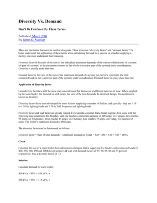
  • 10. Diversity factor for an apartment block Some typical values for this case are given in Figure A10, and are applicable to domestic consumers without electrical heating, and supplied at 230/400 V (3-phase 4-wires). In the case of consumers using electrical heat-storage units for space heating, a factor of 0.8 is recommended, regardless of the number of consumers. Number of downstream consumers Diversity factor (ks) 2 to 4 1 5 to 9 0.78 10 to 14 0.63 15 to 19 0.53 20 to 24 0.49 25 to 29 0.46 30 to 34 0.44 35 to 39 0.42 40 to 49 0.41 50 and more 0.38 Fig. A10: Example of diversity factors for an apartment block as defined in French standard NFC14-100, and applicable for apartments without electrical heating Example (see Fig. A11): 5 storeys apartment building with 25 consumers, each having 6 kVA of installed load. The total installed load for the building is: 36 + 24 + 30 + 36 + 24 = 150 kVA The apparent-power supply required for the building is: 150 x 0.46 = 69 kVA From Figure A10, it is possible to determine the magnitude of currents in different sections of the common main feeder supplying all floors. For vertical rising mains fed at ground level, the cross-sectional area of the conductors can evidently be progressively reduced from the lower floors towards the upper floors. These changes of conductor size are conventionally spaced by at least 3-floor intervals. In the example, the current entering the rising main at ground level is:
  • 11. the current entering the third floor is: Fig. A11: Application of the diversity factor (ks) to an apartment block of 5 storeys
  • 12. Rated Diversity Factor for distribution switchboards The standards IEC61439-1 and 2 define in a similar way the Rated Diversity Factor for distribution switchboards (in this case, always 1) IEC61439-2 also states that, in the absence of an agreement between the assembly manufacturer (panel builder) and user concerning the actual load currents (diversity factors), the assumed loading of the outgoing circuits of the assembly or group of outgoing circuits may be based on the values in Fig. A12. If the circuits are mainly for lighting loads, it is prudent to adopt ks values close to unity. Type of load Assumed loading factor Distribution - 2 and 3 circuits 0.9 Distribution - 4 and 5 circuits 0.8 Distribution - 6 to 9 circuits 0.7 Distribution - 10 or more circuits 0.6 Electric actuator 0.2 Motors 100 kW 0.8 Motors > 100 kW 1.0 Fig. A12: Rated diversity factor for distribution boards (cf IEC61439-2 table 101) Diversity factor according to circuit function ks factors which may be used for circuits supplying commonly-occurring loads, are shown in Figure A13. It is provided in French practical guide UTE C 15-105. Circuit function Diversity factor (ks) Lighting 1 Heating and air conditioning 1 Socket-outlets 0.1 to 0.2 (1)
  • 13. Lifts and catering hoist (2) ď‚· For the most powerful motor ď‚· For the second most powerful motor ď‚· For all motors 1 0.75 0.60 (1) In certain cases, notably in industrial installations, this factor can be higher. (2) The current to take into consideration is equal to the nominal current of the motor, increased by a third of its starting current. Fig. A13: Diversity factor according to circuit function (see UTE C 15-105 table AC)