
Empfohlen
Weitere ähnliche Inhalte
Was ist angesagt?
Was ist angesagt? (20)
Andere mochten auch
Ähnlich wie Research for CCTV Tower in China
Ähnlich wie Research for CCTV Tower in China (20)
Kürzlich hochgeladen
Kürzlich hochgeladen (20)
Research for CCTV Tower in China
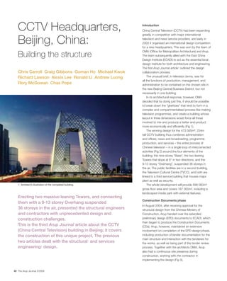
- 1. CCTV Headquarters, Introduction China Central Television (CCTV) had been expanding greatly, in competition with major international Beijing, China: television and news service providers, and early in 2002 it organised an international design competition for a new headquarters. This was won by the team of OMA (Office for Metropolitan Architecture) and Arup. Building the structure The team subsequently allied with the East China Design Institute (ECADI) to act as the essential local design institute for both architecture and engineering. The first Arup Journal article1 outlined the design Chris Carroll Craig Gibbons Goman Ho Michael Kwok collaboration process. Richard Lawson Alexis Lee Ronald Li Andrew Luong The unusual brief, in television terms, was for all the functions of production, management, and Rory McGowan Chas Pope administration to be contained on the chosen site in the new Beijing Central Business District, but not necessarily in one building. In its architectural response, however, OMA decided that by doing just this, it should be possible to break down the “ghettoes” that tend to form in a complex and compartmentalised process like making television programmes, and create a building whose layout in three dimensions would force all those involved to mix and produce a better end-product more economically and efficiently (Fig 1). The winning design for the 473 000m2, 234m tall CCTV building thus combines administration and offices, news and broadcasting, programme production, and services – the entire process of Chinese television – in a single loop of interconnected activities (Fig 2) around the four elements of the building: the nine-storey “Base”, the two leaning Towers that slope at 6° in two directions, and the 9-13 storey “Overhang”, suspended 36 storeys in the air. The public facilities are in a second building, the Television Cultural Centre (TVCC), and both are linked to a third service building that houses major plant as well as security. 1. Architect’s illustration of the completed building. The whole development will provide 599 000m² gross floor area and covers 187 000m², including a landscaped media park with external features. Erecting two massive leaning Towers, and connecting Construction Documents phase them with a 9-13 storey Overhang suspended In August 2004, after receiving approval for the 36 storeys in the air, presented the structural engineers structural design from the Chinese Ministry of and contractors with unprecedented design and Construction, Arup handed over the extended construction challenges. preliminary design (EPD) documents to ECADI, which then began to produce the Construction Documents This is the third Arup Journal article about the CCTV (CDs). Arup, however, maintained an extensive (China Central Television) building in Beijing; it covers involvement on completion of the EPD design phase, the construction of this unique project. The previous including production of tender documentation for the main structure and interaction with the tenderers for two articles dealt with the structural1 and services the works, as well as being part of the tender review engineering2 design. process. Together with the architects OMA, Arup also had a continuous site presence during construction, working with the contractor in implementing the design (Fig 3). 40 The Arup Journal 2/2008
- 2. VIP elevators 2002 2003 2004 2005 2006 2007 2008 Competition Jury decision Executive elevators 22 December 2002: Contract negotiation signing of design contract Express elevators Scheme design stage Extended preliminary design stage Tower lobby Structural expert panel Tower 8 January 2004 review approval lobby Extended preliminary design revisions Construction 28 April 2006: construction documents stage documents approval 22 September 2004: Excavation groundbreaking ceremony Piling and raft 28 April 2005: main Construction phase Public foundations contractor enters site lobby Basement Superstructure 13 February 2006: Public space and circulation steelwork steel installation started Cladding installation Sky studio Fit-out 1 August 2007: construction of Overhang starts 8 December 2007: connection of Overhang 26 December 2007: Overhang connection ceremony 27 March 2008: topping-out ceremony 3. CCTV timeline. Broadcasting Studios Studios As previously described1, the building’s shape and form meant that it fell outside the prescriptive codes for buildings in China. In consequence, a rigorous series of Open studios meetings was required with an assembled expert panel comprising 12 professors from around China, appointed by the Ministry of Construction. Dialogue with these experts influenced the approach to the design and determined the extent of analysis required to justify the seismic performance of the building. As part of the expert panel approval process1, several suggestions were made that Arup and ECADI subsequently addressed during the CD phase. These included Studios a requirement for three physical tests to be carried out, in order to verify the analytical calculations: Studio and broadcast of the column-brace joint to confirm its performance under cyclical loading, in particular the requirement that failure takes place by yielding of the element rather VIP than at the connection. lounge President suite Executive 1:5 scale models of the project’s non-standard steel reinforced columns. These floor tests resulted from concerns that the high structural steel ratio might lead to VIP lounge reduced ductility. Cafe and meeting Canteen constructed to test the structural performance under several seismic events including a severe design earthquake (known as Level 3 - average return period of VIP 1 in 2475 years). The tests were undertaken by the China Academy of Building lobby VIP lobby Research (CABR) in Beijing, using the largest shaking table outside America or Japan (Fig 4 overleaf). This large-scale shaking table test was of particular interest. In China it is the norm Health for buildings that fall outside the code to be thus studied, and the CCTV model was centre the largest and most complex tested to date. The nature of the testing required the VIP lounge primary structural elements to be made from copper (to replicate as much as possible Central kitchen Sports hall in a scale sense the ductility of steel). The model also included concrete floors Staff canteen Marketing Gym department (approximately 8mm thick) to represent the 150mm thick composite floor slabs. Interestingly, in a scaled model test the duration of the earthquake is also scaled, Staff and VIP facilities so that the severe design earthquake event lasted less than four seconds when applied to the model. 2. Functions and layout within the CCTV building. The Arup Journal 2/2008 41
- 3. In all cases, the physical tests correlated closely with the analysis. It is arguable that computer analysis is now more accurate than a physical shaking table test, which is still the standard practice in China. Due to the amount of scaling required, the accuracy of such models and tests may be significantly less than the proven accuracy of the analytical software used to design the building. Nonetheless, a shaking table test helps to corroborate the computer model and provides a demonstration that the design has safely accounted for seismic issues. Tender, excavation, and foundations As noted already, Arup had a major role in the tender process for appointing the main contractor, including the production of the steelwork drawings and specifications. One key document was the Particular Technical Specification, which placed several requirements on the contractor that were specific to the design of CCTV. Some of the specific issues identified in the Particular Specification included: 4. Shaking table model. convey the weight added to the building at stages during the construction (married to the construction weight assessment) dishing) of the foundations between the position of connection points as the Overhang construction advanced prior to linking movement between the connection points of the 5. Three alternative methods of constructing the Overhang. Overhang were manageable (suggesting connection when the two Towers were at an even temperature, ie at dawn) After the connection was made, any added weight would result in a thrust between the two Towers via the Overhang. The final stresses in the building were therefore very was commensurate with the daily movement much linked to the construction sequence. The Particular Specification defined an measurement, so as to prevent the connection upper and lower bound range of permissible locked-in stress, allowing the contractor ripping apart once it had been firmly made some flexibility in choosing his final construction sequence. Another interesting feature of the process was the proposals put forward by structural elements. different tenderers to meet the Particular Specification requirements and the In addition to regular gravity and lateral forces acting particularly challenging aspects of the Overhang construction. One of the three on the structure, there are significant additional shortlisted tenderers proposed a temporary tower the full 162m height to the construction stage forces due to the fact that the underside of the Overhang, providing a working platform to build the Overhang building comprises two separate leaning Towers with connection in situ. The second tenderer opted to build a partial cantilever from the cantilevers up until the point at which they are joined Towers and then construct the lower part of the Overhang at ground level and strand to become one structure. The additional bending jack the assembly into position. The third tenderer proposed to construct incremental and overturning stresses that get “locked” into the cantilevers from each Tower until the two met and connected at the centre of the Towers and foundations prior to joining depend on Overhang (Fig 5). This latter approach was as described in Arup’s documentation, the amount of structure and façade completed at the though any construction approach was deemed acceptable provided it could satisfy time of connection. the locked-in stress limits defined in the Particular Specification. In essence, the greater the construction load The Particular Technical Specification approach has become a leading example of applied to the building prior to connecting the two best practice for high-rise construction within Arup. Towers, the more this would manifest itself as China State Construction Engineering Corporation (CSCEC) was awarded the main increased locked-in base moments in the Towers. contract in April 2005. CSCEC tendered on this third approach. 42 The Arup Journal 2/2008
- 4. Construction team CSCEC, a state-owned enterprise under the administration of the central government, was established in 1982 and is China’s largest construction and engineering group. CSCEC now enjoys an international reputation, having completed an increasing number of projects abroad including the Middle East, South America and Africa. The steelwork fabricators were Grand Tower, part of the Bao Steel group based in Shanghai (China’s largest steel manufacturer), and Jiangsu Huning Steel, based in Jixing, Jiangsu Province. Other members of the team were Turner Construction (USA), providing support to CSCEC on construction logistics, China Academy of Building Research (CABR), one of the major design institutes in Beijing, and Tsinghua University, which carried out the presetting analysis and is one of China’s foremost universities. The independent site supervisor was Yuanda International, established in 1995 (Fig 6). 8. Preparation of foundation raft. 6. Site set-up and roles. Client China Central Television (CCTV) Client’s project manager China Central Television New Site Construction Ltd Site supervisor ("Jian Li") Main contractor Design team Yuanda International CSCEC OMA Arup ECADI Logistics advice Steel fabricators Design and analysis Other subcontractors 9. Delivery of column baseplate, April 2006. Turner Construction Grand Tower Tsinghua University (USA) (Presetting analysis) Jiangsu Huning Steel China Academy of The two Towers are supported on separate piled raft Building Research foundations with up to 370 reinforced concrete bored (Movement monitoring) piles beneath each, typically 33m long and up to 1.2m in diameter. In total, 1242 piles were installed during the spring and summer of 2005. In common Excavation and foundations with many other Beijing projects, the piles were The ground-breaking ceremony took place on 22 September 2004, and the shaft- and toe-grouted (in accordance with an excavation of 870 000m3 of earth began the following month under an advance alternative design by CABR). The top 2m of the piles contract. Strict construction regulations in Beijing meant that spoil could only be were then topped off by hand rather than with removed at night: nonetheless, up to 12 000m3 of soil was removed each day, machinery (Fig 7) - one of the few occasions when the entire excavation taking 190 days. Dewatering wells were also installed, since sheer numbers of workers had to be mobilised to the groundwater level was above the maximum excavation depth of 27.4m below carry out the work: such unskilled, labour-intensive existing ground level. tasks were few on this project. The Tower rafts were constructed over Christmas 2005 (Fig 8). The 7m thick reinforced concrete slabs 7. Cutting down piles by hand. each contain up to 39 000m3 of concrete and 5000 tonnes of reinforcement. Each raft was constructed in a single continuous pour lasting up to 54 hours. At one stage, 720m3 of concrete was being delivered every hour, using a relay of 160 concrete trucks from three suppliers. Chilled water pipes were embedded inside the pour and temperatures were monitored for more than two weeks to ensure that the concrete did not experience too high a temperature gradient during curing. The two rafts, poured within days of each other, were the largest single continuous concrete pours ever undertaken by China’s building industry. In total, 133 343m3 of concrete went into the foundations of the Towers and podium. The Arup Journal 2/2008 43
- 5. The seismic analysis indicated that some columns and their foundation piles could experience tension during a severe design earthquake. Some of the perimeter columns and their baseplates were therefore embedded 6m into the rafts to enhance their anchorage (Fig 11). Certain piles were also designed for tension. Steelwork construction Top of raft The first column element was placed on 13 February 2006 (Fig 12). In total, 41 882 steel elements with a combined weight of 125 000 tonnes, including connections, were erected over the next 26 months, at a peak rate of 8000 tonnes per month. During the design it was thought that some high-grade steel elements would need to be imported, but in the end all the steel came from China, reflecting the rapid advances of the country’s steelwork industry. Steel sections were fabricated at the 7m yards of Grand Tower in Shanghai and Huning in Jiangsu, and then delivered to site by road (Fig 9), with a size limit of either the tower crane capacity (80 tonnes at a distance of 12m) or the maximum physical dimensions that could be transported (18m length). Inspections generally took place prior to shipping, with further checks prior to installation. Only minor fabrication work was carried out on site. The size of the site enabled many elements to be stored after delivery (Fig 13), Bottom of raft although heavier ones were kept on the backs of trailers until they could be craned directly into position. Due to the many different elements, each was individually coded 11. Column embedded in raft. to identify its location and orientation. The elements were lifted into place by two tower cranes working inside each 12. Installation of first column. Tower. These were Favco M1280D cranes imported from Australia – the largest ever used in China’s building industry - plus a smaller M600D crane. Even so, care was needed when locating the temporary ground-level working platforms to which the elements were delivered for craning, to ensure that all parts of the sloping Towers stayed within the cranes’ operating radius as their height progressively increased. Each crane not only had to be raised up to 14 times during construction, but also slewed sideways up to four times when it reached the upper levels, to maintain position relative to the edges of the progressively shifting floorplate (Fig 10). 10. Crane slewing process. 13. Prefabricated elements stored on site. (a) Cranes erected (in lift shafts) at (b) As building height increases, (c) Due to shifting floorplate, crane ground level. cranes progressively lifted by must be relocated horizontally so jacks. as to reach extremity of building. 14. Craning in action. (d) First crane used to dismantle (e) First crane used to reassemble (f) Both cranes resume work. second crane. second crane in new position. 44 The Arup Journal 2/2008
- 6. Due to the 6˚ slope of the Towers, the perimeter elements needed to be adjusted to approximately the correct installation angle after being lifted a short distance off the ground, using a chain block. This simplified the erection process at height. The vertical core structure was generally erected three storeys ahead of the perimeter frame. This meant that the perimeter columns could be initially bolted in place and braced to the core columns with temporary stays, then released from the tower crane before final surveying and positioning. The welders could then start the full-penetration butt welds required at every connection: a time-consuming task (a) Lower box section requiring shift work to achieve a continuous 24-hour process. fabricated on site. The maximum plate thickness of the columns is 110mm and the volume of weld sometimes reaches as much as 15% of the total connection weight. At the extreme case, a few connection plates near the base of the Tower required a 15m long site (b) Staggered splices allow splice of 100mm thick plate, each taking a week to complete. The plate thickness of access for welding second box section. some elements exceeded the maximum assumed in design, which had been determined by likely steel availability. Onerous material specifications were laid out for thick sections to ensure satisfactory performance. The welders had to be specially qualified for each particular welding process. Before the start of a given weld, the welder’s qualification, the electrodes, scaffolding safety, the preheating temperature, and the method would all be checked. Procedures were laid down for monitoring preheating temperatures, the interpass temperature, (c) Filler section installed and Life on site welded in place. An average of 1200 workers were on site at any one time, rising to 3500 at peak of construction. (d) Box sections encased in They ranged from unskilled migrant labourers to reinforced concrete. experienced welders and top-level management. CCTV actually employed far fewer labourers than 17. Weld process for complex section. other large projects in the city, since the building contains a limited amount of conventional reinforced concrete construction (by contrast almost 50 000 were employed on Beijing Airport’s and any post-heating treatment. Non-destructive new terminal). The men, and a few women, testing 24 hours after completion was carried out by usually worked 8-10 hour days. In 2007, construction workers in Beijing could typically the contractor, site supervision company, and third earn up to £120 per month - a considerable sum 15. parties employed by the client. by rural income standards - with workers sending Though, following standard Chinese practice, much of this home to support their families. affected by homesickness in the lead-up to the Accommodation and food were usually provided all quality control was carried out by the independent Spring Festival, or by workers suddenly returning by the contractor. Most lived in dormitories on the to farms in the surrounding provinces during the site supervisor, Arup maintained a site presence to outskirts of Beijing, provided by the contractor, wheat harvest season between May and June. observe progress and provide a liaison with the although some actually lived on the site. Mealtimes are possibly the most important part of architect and client, due to the project’s complexity. The workers hail from all parts of China, and the day, with the site almost coming to a standstill generally return home for two weeks once a year at lunchtime, except for the non-stop sparks from Some of the most complex sections required during the Spring Festival (Chinese New Year). welders. During summer evenings, outdoor film careful thought to achieve a full weld, with staggered The site meeting minutes recorded some unusual screenings were arranged for workers in public splices used in some cases to reduce concentrations working concerns: for example, productivity being squares near the site. of weld stresses where possible (Fig 17). The geometrical complexity made construction 16. Welding in process. slower than for other steel-framed buildings. Although the rate of erection increased as the contractor became more familiar with the process, CCTV has no “typical floors”. Nevertheless, up to six storeys per month was achieved for the relatively uniform levels at Tower mid-height. Concreting the composite columns and floor slabs took place several storeys behind steel erection, off the critical path. The Arup Journal 2/2008 45
- 7. 18. Basic concept of Movements and presets presetting for a sloping Tower. Arup’s calculations included a “construction time history” analysis to take account of the effects of the predicted construction method and sequence on the completed building’s deflections and built-in forces. This indicated that the corner of the Overhang would move downwards by approximately 300mm under the building’s dead weight. For there to be no overall downward deflection under this load case, the whole structure needed to be preset upwards and backwards to compensate (Fig 18), and the (a) Tower deflects under its own weight. contractor continuously monitored construction to ensure that the actual movements corresponded to analysis assumptions and predictions. The presetting process was further complicated by the fact that when completed, almost all the columns have different stresses, depending on the ratio of gravity to seismic loads, unlike in a conventional building where all perimeter elements will be similarly stressed. As a result, different presets were required on different sides of the Towers, the exact values also depending on the final construction (b) Preset upwards and backwards. sequence. In practical terms, this meant fabricating the columns longer on one side of each Tower, so that they would eventually shorten to the correct geometry under load. Presetting was in two stages: at the fabrication 20. Large “butterfly” plate. yard, based on the results of the analytical modelling, and then at installation, if required, to suit the actual building deformation as monitored during the course Overhang construction of construction. Progress of floor plate concreting Construction of the Overhang began after the was also controlled to suit the assumptions made in steelwork for the two Towers was completed to roof (c) Resultant: no deflection the presetting estimation. level. Tower 2 Overhang began first, in August 2007, under self-weight. The contractor commissioned CABR to carry out and the structure was cantilevered out piece-by- the movement monitoring, while Tsinghua University piece from each Tower over the course of the next performed the building movement prediction and five months (Fig 22). This was the most critical presetting analysis as required by the Arup construction stage, not only in terms of temporary specification. This required a more detailed time stability but also because its presence and the way it history analysis of the final construction sequence, was built would change the behaviour of those parts dividing the process into 53 assumed stages based of the Tower already constructed. The forces from the on estimated progress for the perimeter tube, core, two halves of the partly constructed Overhang would slab concreting, façade, services, and interior fit-out. be concentrated in the Towers until such time as the This was compared with the results of the movement two halves were linked and the building became a monitoring, and checks and adjustments were made single continuous form, when the loads would start as necessary. being shared between all of the permanent structure. The studies found that the movements during The bottom two levels of the Overhang contain Overhang construction would be far more significant 15 transfer trusses that support the internal columns than those at the earlier stages caused by the and transfer their loads into the external tube. In the Towers’ lean only. Due to the large number of corner of the Overhang, these trusses are two-way, variables needed for the presetting calculation resulting in some complex 3-D nodes with up to (variable axial stiffness, final construction sequence, 13 connecting elements, weighing approximately 19. CCTV under foundation settlement, thermal movements, etc), 33 tonnes each. construction at times presented the main focus of the analysis was on the critical Fabrication accuracy was therefore crucial for almost surreal vistas Overhang construction stage. By the time Overhang this part of the structure, with erection being carried from surrounding streets. erection commenced, there was already much out piece-by-piece 160m above ground level. movement data from the Tower construction that Trial assembly of these trusses at the fabrication yard could be used to calibrate the analysis. prior to delivery was essential to ensure that minimal adjustment would be needed at height. 46 The Arup Journal 2/2008
- 8. 21. The seven initial connection elements. 24. The completed Overhang structure, showing the three 3m diameter circles punched in the deck to create glazed viewing platforms for the public viewing gallery. 22. The Overhang before connection. Prior to connection, the two Towers would move independently of each other due to environmental conditions, in particular wind and thermal expansion and contraction. As soon as they were joined, therefore, the elements at the link would have to be able to resist the stresses caused by these movements. As a result, the connection strategy required a delay joint that could allow a sufficient number of elements to be loosely connected between the Towers, then locked off quickly to allow them all to carry these forces safely before any relative movement took place. Arup specified that this should take place early in the morning on a windless day, when the two Towers would be at a uniform temperature and the movements at a minimum. In the lead-up to connection, Arup’s specification required one week of monitoring of global and relative movements so that the correct dimensions of the linking elements could be predicted. The relative movements of the Towers during the day were found to be around ±10mm. The contractor made the final measurements of the gap exactly 24 hours beforehand (ie at identical ambient conditions) so that final 23. Installation of first connection element. adjustments could be made to the length of the linking elements while they were still on the ground prior to installation. The contractor chose to connect seven link elements at the inside corner of the Overhang during this initial connection phase (Fig 21). These were lifted into place – to less than 10mm tolerance – and temporarily fixed with pins in the space of a few minutes at 9.00am on 8 December 2007, before the Towers started to move relative to each other (Fig 23). The pins allowed them to carry the thermal loads while the joints were fully welded over the following 48 hours. The specification originally called for the connection to take place while ambient temperatures were between 12-28°C (ie close to the standard room temperature assumed in analysis). Since the connection took place during winter, the temperature at the time was around 0°C, so further analysis of the structure was carried out by the design team to check the impact of the increased design thermal range. The Arup Journal 2/2008 47
- 9. Follow-on trades Installing the façade began once the structure had reached mid-height, so the façade design needed to take account of significant movements subsequent to installation. This sequencing also created tricky interfacing problems due to the need to share tower crane use with the steel erection, and cope with protecting workers – and completed cladding – from work taking place above. The lean of the Towers meant that workers on the re-entrant sides of the Tower would be protected from falling objects above (albeit with additional installation hurdles to overcome), while extra care would be needed to protect those on the other faces which were subject to higher risk. Services installation also began while the structure was in progress. This fast-track process was in 25. Façade build-up. marked contrast to many other projects in the city, in which façade and MEP installation would sometimes only start once the structure had been completed. Once the initial connection was made, the remainder of the Overhang steelwork was progressively installed. With the building now acting as one entity, the Overhang was propping and stabilising the two Towers, and continued to attract locked-in stresses 26. Construction progress at March 2008. as further weight was applied. In addition to the primary steelwork elements, a continuous steel plate deck up to 20mm thick was laid down on the lowest floors of the Overhang to resist the high in-plane forces that were part of this propping action. The steel plate is not, in fact, fully continuous – three 3m diameter circles were punched into the deck to provide glass viewing platforms for the public gallery at the Overhang’s bottom level (Fig 24). The concrete floor slabs were only added once the entire primary structure had been completed, so as to reduce the loads during the partially-constructed stage. Again, the construction stage analysis needed to take account of this sequencing. A topping-out ceremony on 27 March 2008, on a specially-constructed platform at the corner of the Overhang, marked the completion of the steelwork installation. Post-installation of key elements Arup’s early analysis showed that the corner columns on the inside faces of the Towers would attract a huge amount of dead load from the Overhang, and thus have little spare capacity for resisting seismic loads. Increasing the column sizes was rejected since they would become stiffer and hence attract even higher loads. Instead, the corner column and brace elements directly below the Overhang were left out until the end of construction, forcing the dead loads to travel via the diagonals down adjacent columns and enabling the full capacity of the corner elements to be available for wind and seismic loads in the as-built condition. Key elements at the intersection of the Towers and podium were also post-fixed for similar reasons. In addition, this process enabled the architectural size of the elements to be controlled, while giving the contractor additional flexibility to deal with construction movements. Delay joints were introduced between the Towers and the Base to allow for differential settlement between the two structures’ foundations. It should be noted that over half the predicted settlements were expected to take place after the Towers were constructed to their full height, due to the disproportionate effect of the Overhang on the forces in certain columns. These were fully closed after completion of the main structure. Further late-cast strips were also provided at several locations around the basement to control shrinkage. 48 The Arup Journal 2/2008
- 10. 27. The façade design includes large diagonal “diagrid” elements that span between each primary floor, mirroring the structural braces. Novel construction solutions for a novel building The other faces also involved challenges. Reinforcement bars The glazing panels were lifted up individually Spare reinforcement is used for almost The challenge of constructing a vast, cranked, leaning building made by rope, but on the outer faces of the everything on a Chinese construction site - the contractor devise some other intriguing solutions. Towers, men were needed on the ground to handrails for temporary staircases (and pull the rope sideways to keep the panels sometimes the staircases themselves); Cutting down piles Then, with the help of a Tirfor winch, away from the Tower as they were lifted, to impromptu hammers and other tools; drain The wide availability of unskilled labour in the mass-concrete pile top could simply prevent damage to glazing already installed. covers. Very few offcuts go to waste. China means that many operations are be snapped off. Meanwhile, almost all reinforcement used in Surveying carried out in a very different manner from Façade installation the permanent works is coupled rather than Not one of the 121 columns in either Tower’s the West. On CCTV, for example, piles were lapped – material costs are still the main The façade design includes large diagonal perimeter frame is vertical, and many of the cut down by hand, with hammer and chisel, driver in China. “diagrid” elements that span between each pieces in the Base and Overhang are aligned to expose the reinforcement (Fig 7). primary floor, mirroring the structural braces in completely different directions. To ensure Recycling While this avoided workers suffering from (Fig 27). These heavy pieces had to be lifted every element was positioned correctly, As is standard in China, virtually nothing Vibration White Finger, a condition that with the tower cranes, but on the re-entrant the contractor continuously monitored the from the site demolition or new building went often affects those working with vibrating faces, the slope of the Towers meant that it control points throughout the building, to waste. Every brick, nail, pipe, and piece of machinery like drills, this was still a very was impossible to get them close enough to reaching 670 in number at the most critical timber and reinforcement was meticulously time-consuming process, and other the edge of the floor to fix them in position. stage around January 2008 after the linking extracted and collected by a team of methods were developed to speed things The contractor came up with an ingenious of the two Towers. Monitoring included workers, before being used again on site or up. Once the outer part of the pile had been system of supporting the element off a vertical movements of Tower circumference sent away for reuse or recycling. broken back, a notch was cut into the counterbalanced “mini-crane”, hanging at particular floors, corner column central part, and cables were tightened on the end of the main crane cable. movements at the Overhang soffit, around the remainder of the section. This allowed a team inside the Tower to internal levelling, stress, raft settlement, manoeuvre the piece laterally into position. and Overhang movement. The Arup Journal 2/2008 49
- 11. Chris Carroll is a Director of Arup in the Buildings London 7 group. He led the structural design of the CCTV headquarters. Dr Craig Gibbons is a Director of Arup in the Gulf group, and is Country Leader for the United Arab Emirates. He was the Project Manager for the CCTV headquarters. Dr Goman Ho is a Director of Arup in the Beijing office. He led the structural team in the Beijing office for the CCTV headquarters. Michael Kwok is a Director of Arup and leads the Shanghai office. He was the Project Director for the CCTV headquarters. Richard Lawson is an Associate of Arup in the Buildings London 7 group. He was a structural engineer for the CCTV headquarters. Alexis Lee is a Director of Arup in the Hong Kong B group. He was the acting project manager for the CCTV headquarters. Ronald Li is a senior engineer in Arup’s Vietnam group. He was the Resident Engineer for the CCTV headquarters. Andrew Luong is an Associate of Arup in the Hong Kong B group. He was a structural engineer for the CCTV headquarters. Rory McGowan is a Director of Arup China, Beijing office. He was leader of the competition and design team for the CCTV headquarters. Chas Pope is an Associate of Arup in the Beijing office. He was a structural engineer for the CCTV headquarters. 28. The TVCC building, to the left of the CCTV headquarters, April 2008. TVCC and the Service Building Credits Client: China Central Television Architect: OMA The other buildings on site, TVCC (Fig 28) and the Service Building, were built Stedebouw BV, Ole Scheeren and Rem Koolhaas simultaneously. Construction of the Service Building began in April 2006, and it was Structural, MEP, geotechnical, fire, and security handed over in June 2008. consultant: Arup - Abdel Ahmed, Cecil Balmond, Carolina Bartram, Chris Carroll, Wayne Chan, Mark Choi, The Service Building was actually the critical path item, as it had to be complete Dean Clabrough, Paul Cross, Roy Denoon, Omar Diallo, and fully commissioned in advance of CCTV and TVCC. Service tunnels running Mimmy Dino, Xiaonian Duan, Gary Ge, Craig Gibbons, between the three buildings introduced a significant element of civil engineering works Sam Hatch, Colin Ho, Goman Ho, Jonathan Kerry, Michael Kwok, Richard Lawson, Alexis Lee, Jing-Yu Li, to the site. Ronald Li, Zhao-Fan Li, Peng Liu, Man-Kit Luk, Andrew The contract for TVCC was given to a separate contractor, Beijing Urban Luong, John McArthur, Rory McGowan, Hamish Nevile, Construction Group. Work began in March 2005, and the structure was complete by Jack Pappin, Steve Peet, Dan Pook, Chas Pope, Andrew Smith, Stuart Smith, Alex To, Felix Tong, Paul Tonkin, September 2007. TVCC and the Service Building will be described in detail in a future Ben Urick, Bai-Qian Wan, Yang Wang, Yi-Hua Wang, issue of The Arup Journal. Will Whitby, Robin Wilkinson, Michelle Wong, Stella Wong, Eric Wu, Lucy Xu, Angela Yeung, Terence Yip, Conclusion George Zhao (geotechnical, structural) Main contractor: China State Construction Engineering Corporation The structure of the CCTV building was completed in May 2008, with the façade due Steelwork contractors: Grand Tower; Jiangsu Huning to be finished by the start of the Beijing Olympic Games. Within weeks of structural Steel Construction logistics: Turner Construction Building movement monitor: China Academy of Building completion, China was struck by its most violent earthquake of recent years. Research Presetting analyst: Tsinghua University Although the epicentre was nearly 1000 miles from Beijing, the tremor was felt on site. Independent site supervisor: Yuanda International Like other structures in seismic regions, CCTV is designed to resist a certain level of Illustrations: 1, 2, 25 OMA; 3, 6, 10, 17 Nigel Whale; 4, 12, 14, 16, 19, 23, 27, 29 Chas Pope; 5, 8, 18 Arup; earthquake during construction, and no damage was reported. However, this served 7, 9, 11, 13, 15, 20 Rory McGowan; 21 CSCEC; 22, 24, as a timely reminder of the importance of the building’s rigorous seismic design and 26, 28 ©Arup/Frank P Palmer. approvals process. That the contractor could construct such a vast and complex building with few delays was a credit to the design team and to CSCEC, in particular the attention paid References to devising a feasible construction sequence from an early stage, and the careful (1) CARROLL, C, et al. CCTV Headquarters, Beijing, China: thought about the buildability of the primary structural elements and connections. Structural engineering design and approvals. The Arup Journal, 40(2), pp3-9, 2/2005. (2) GREEN, G, et al. CCTV Headquarters, Beijing, China: Services engineering design. The Arup Journal, 40(3), pp22-29, 3/2005. 50 The Arup Journal 2/2008
- 12. 29. The scale of the completed structure is emphasised by the quantity of site works that were still in progress around its base in August 2008. The Arup Journal 2/2008 51