1. Innovative Highway Stabilisation on Rimutaka Hill Road
Selvem Raman
Opus International Consultants, Wellington, New Zealand
Keywords: Slope Stability, Soldier Pile, Ground Improvement Piles, Rock Anchors
ABSTRACT
A section of the SH2 Rimutaka Hill Road was affected by a dropout caused by storm events.
Transit New Zealand let a “design and build” tender for the design and construction of a 70 m
long retaining structure supporting the road formation to reinstate the affected traffic lane. The
instructions for tendering indicated that the specimen design which was a contiguous bored pile
wall does not meet the principal’s requirements.
A cost effective design solution consisting of a combination of unanchored and anchored (rock
anchors) soldier pile wall, and ground improvement piles was developed to provide the required
performance. This considers the varying depth of bedrock level below existing ground. A
shotcrete facing was provided to support the ground between the piles to transfer the load to the
piles.
Trench cut-off drains, sub-horizontal drainage holes, additional sumps, discharge culverts with
extended flexible hoses, weepholes and stripdrains were installed to reduce the groundwater
pressures and improve stability.
The design considered the importance of the highway as a key arterial road and also Transit’s
desire for a 50 year design life and 0.2g peak ground acceleration earthquake design.
1 INTRODUCTION
In February 2004, the Wellington Region was hit by a number of major storm events that had a
significant impact on the state highway network. The Rimutaka Hill Road on State Highway 2
suffered a number of dropouts. Of these sites, Site 7, which is located at RP 921/9.55
approximately 850 m east of the Rimutaka Summit, is a large dropout with a surface area of
approximately 850 m2. The total length of highway affected was about 70 m.
Following heavy rainfall in June 2005, a larger slip occurred immediately east of the February
2004 slip. The head scarp of this slip encroached to the edge of the road. Tension cracks within
the east bound lane developed above the slip and into the carriageway. Both slips converged
downslope leaving a large potentially unstable wedge of soil between the two.
Transit New Zealand (Principal) let a “design and build” (DB) tender, for the design and
construction of a 70 m long retaining structure and all the necessary ancillary works in
supporting the road formation at Site 7. MWH, the region’s network management consultant,
was the Principal’s Advisor, and had undertaken the site investigations and preliminary design.
Fulton Hogan (FH) approached Opus International Consultants (Opus) to be the Designer for
the project. Subsequently, FH with Opus collaboration, won the DB contract.
2 PRINCIPAL'S REQUIREMENT
A specimen design was made available in the tender document for contractor’s information.
However, the tender document clearly stated that the Specimen Design does not meet the
2. Principal’s requirements. The DB contractor was required to prepare and submit a new tender
design which meets all the principal’s requirements (Transit New Zealand, 2006).
The design had to be in compliance with the Transit New Zealand Bridge Manual. The design
was required to be carried out for a design durability life of 50 years. The Principal’s
requirement specified that the retaining system should be designed for a reduced seismic load
corresponding to a 100 year return period earthquake with a peak ground acceleration of 0.2g.
The reduced PGA was due to Transit’s expectation that this section of the Rimutaka Hill road
would be realigned in about 20 years time.
3 LOCATION AND SITE TOPOGRAPHY
The slip site is shown on Figure 1. The slip and site features are shown on Figure 2. The slips
are located on a north facing slope, downhill from the summit. A large soil wedge remains
intact between two north facing headscarps, immediately below the road. The site is mostly
covered with thick bush and shrubs both uphill and downhill from the road. At this section SH2
is a two lane road with a west-bound passing lane. The passing lane was closed following the
slips, and two lane access was maintained. Rock exposures can be observed on the cut batter
flanking the road on the south side.
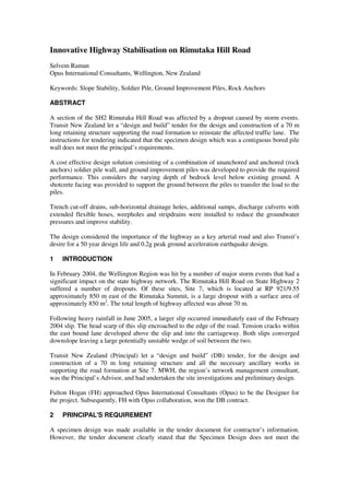
Project Site
Figure 1: Project Site Location
There are two culverts located below the existing road at both northern and southern ends of the
section to discharge the water from the roadside stormwater drain at the southern side of the
road. The culvert outlets were discharging on to the slope below the road through the use of
drainage socks. Cracking in the pavement extending approximately 2 metres into the
carriageway was noted in August 2005. Further cracking in the road pavement was observed in
February 2006 and was located along the eastbound lane/middle lane white line.
Figure 2: layout of the Slip and Site Features
3. 4 GEOLOGY & GROUND CONDITIONS
The bedrock in this area is the Esk Head belt formation of the Torlesse Supergroup (Institute of
Geological and Nuclear Sciences, 2000). This deformed rock belt consists of Greywacke
sandstone and argillite dominated sequence with varying degrees of deformation.
The ground conditions at the site comprise generally medium dense to loose silty sandy gravel
and gravely silt, underlain by very dense gravely silt and silty gravel with some cobbles and
boulders. The overburden soils are underlain by slightly to moderately weathered interbedded
sandstone and mudstone, weak to very strong. The bedrock depth is generally up to 13 m with a
deeper section up to about 18 m at eastern side of the section. Groundwater monitoring
indicated that the groundwater is at or up to a metre above the overburden-bedrock interface.
5 GEOTECHNICAL ASSESSMENT
The fill slope supporting the eastbound lane was found to be of marginal stability, as indicated
by the cracking within the pavement. The slip on the slope below the road has created
oversteepened head scarps, with a large potentially unstable wedge of soil between two slip
headscarps. The site therefore is vulnerable to failure in future storm or earthquake events. The
slip is within the fill and colluvium on which the road is constructed. The slip is a shallow
translational type failure that occurred within the fill.
The slip is presumed to have occurred during prolonged and intense rainfall events that
saturated the soils in the steep slope resulting in failure. The uncontrolled discharge from the
two stormwater culverts, directly onto the slope may have also contributed to the erosion and
undercutting of the slope. The thick loose overburden soils, the highly fractured and sheared
greywacke bedrock and a significant variation in bedrock level presented challenging
geotechnical issues.
6 REMEDIAL DESIGN CONCEPTS
Various remedial design concepts were explored and discussed with the DB contractor during
the tender stage. The involvement of the contractor helped in evaluating cost effectiveness of
different proposals. The following concepts were considered during tender stage:
• Contiguous bored piles with 2 levels of rock anchors (specimen design),
• Soldier piles with rock anchors,
• Soldier piles with deadman anchors,
• Soil nailing of the slope below the road and
• 3 rows of concrete columns along the edge of the road.
The final remedial concept was chosen to accommodate large variations in the bedrock level
(from existing ground level to 18 m depth), and allow construction from within the limited
space available. The final remedial design concept comprised a combination of:
• Unanchored Soldier Pile wall, where depth to bedrock is up to 3 m
• Anchored Soldier Pile wall, where depth to bedrock is 3 m to 13 m
• Ground Improvement Piles, where depth to bedrock is greater than 13 m
The design concept will support the road formation, and isolate the highway from any potential
future slope instability below. Figure 3 presents the longitudinal section along the retaining
wall showing the inferred bedrock profile and the combination of different options within the
wall section.
4. Figure 3: Longitudinal Section of the Wall
7 DETAILED DESIGN
7.1 Tender Award
FH sumitted the tender based on the final remedial concept. Based on the robust and cost effect
design concept, the DB contract was awarded to FH with Opus as its designer. Subsequently,
Opus developed the detailed design which was reviewed both internally (within Opus) and
externally (by an independent consultant), and approved for construction.
7.2 Detailed Design
7.2.1 Soldier Pile Wall
The soldier piles comprised:
• 600 mm diameter piles at 2 m centres, for bedrock depths of up to 8 m
• 900 mm diameter piles at 2 m centres, for bedrock depths between 8 m and 10 m
• 1200 mm diameter piles at 2 m centres, for bedrock depths between 10 m and 13 m
The soldier piles are reinforced concrete bored piles socketed into bedrock. The soldier piles
supporting more than 3 m height of overburden (above bedrock) were tied-back with a rock
anchor at 1.5 m below the top of the wall. Figure 4 shows a typical detail of the anchored soldier
pile. A shotcrete facing is provided for the upper 2.5 m height of the soldier pile wall below
road level to support the ground between the piles and to transfer the local earth pressure to the
piles.
Figure 4: Typical Detail of the Anchored Soldier Pile Wall
7.2.2 Rock Anchors
The rock anchors were installed at 1.5 m below road level to enable practical construction,
without having to excavate too far below the road and also to minimise bending moments in the
pile. The rock anchors were installed through the bored piles.
5. The rock anchors comprise of 500 MPa multiple Strand Anchors. The anchors were designed to
transfer the wall loads to the bedrock through a fixed bond length in the slightly weathered rock.
Three anchor pull-out tests were undertaken before installation of production anchors, to
confirm the grout-rock bond capacity. The anchors were designed for a grout-rock ultimate
bond capacity of 900 kPa based on the pull-out test results. All the anchors were subjected to
acceptance testing prior to lock-off. Figure 5 shows a typical detail of the rock anchor installed.
Figure 5: Typical Rock Anchor Details
7.2.3 Ground Improvement Piles
Ground inprovement piles were installed in the section where the bedrock depth is greater than
13 m. Ground improvement piles are 600 mm diameter reinforced concrete bored piles installed
in a triangular grid pattern. The ground improvement piles were chosen due to the deep bedrock
level. A soldier pile solution would have required larger piles with higher capacity multiple
level anchors to withstand the large loads. Figure 5 shows a schematic section through the
ground improvement piles.
Figure 5: Typical Ground Improvement Piles Details
The ground improvement piles were found to be more cost effective and practical than the large
diameter soldier piles and multiple anchors. Soil-pile interaction was considered in the design of
ground improvement piles. The reinforcement in the piles improved the bending capacity of the
piles and provided confinement to the concrete so that the piles will behave in a ductile manner
and withstand displacements, even in a earthquake events larger than the design earthquake
event.
A shotcrete wall was installed along the middle pile for the road above to be supported.
Movement joints were provided in the shotcrete wall between the soldier piled section and the
section strengthened by ground improvement piles, to allow for differential movement during
earthquake.
7.3 Drainage Measures
Various drainage measures were provided to reduce the groundwater pressures on the retention
systems and improve the overall stability of the slope below. Strip drains and weep holes were
installed behind and through the shotcrete face. A trench cut-off drain was installed at the uphill
side of the highway and connected to the existing culverts to intercept the large seepage flows
6. from the hillside into the road formation. Sub-horizontal drainage holes were installed at 4 m
spacing in the slope to penetrate into bedrock at a level about 5 m below the road level. These
will intercept the groundwater flow above the bedrock interface. The sub-horizontal drainage
holes were installed with alternate holes having different inclinations to target different depths
where the drains enter bedrock. The discharge from the culverts flow through flexible hoses
connected to the outlets and secured down the slope using warratah stakes.
8 CONSTRUCTION
The construction of the remedial works was carried out between April and November (2007).
Sufficient quality control measures proposed for wall elements during the detailed design stage
were executed to ensure that the design requirements are met.
A new “W” section guardrail was installed and connected to the existing guardrail at the uphill
end (Upper Hutt end) and terminates in a terminal end at the downhill end (Featherston end) of
the wall. The slope immediately below the road section was hydroseeded to minimise further
erosion and discharge of sediments down the slope. The road within the wall section was
resurfaced prior to completion of the works.
The completed wall is shown in Figure 6.
Figure 6: Photograph of the Completed Wall
9 CONCLUSIONS
The innovative design concepts provided a cost effective and robust solution to the dropout
repair at Rimutaka Hill Road. The DB procurement method adopted facilitated close
cooperation between the contractor (FH) and designer (Opus) during tender design, detailed
design and construction. The design recognised Transit’s performance expectations for this
section of highway and provided an innovative, practical and cost effective solution.
REFERENCES
Institute of Geological and Nuclear Sciences (2000) Geology of the Wellington area, scale
1:50,000. Geological Map 22. Prepared by Begg, J.R. and Johnston, M.R.
Transit New Zealand (2006) Contract 494PN, SH2 Rimutaka Dropout Site 7 Remedial Works.
Contract Documents.
Transit New Zealand (2003) Bridge Manual. Prepared by Opus International Consultants.