SlideShare ist ein Scribd-Unternehmen logo
1 von 18
Starter motor drive mechanism
by
Mr. P. Karthik selvan, AP
• The starting motor is located near the flywheel .The drive gear on
the starter is arranged so that it can mesh with the teeth on the
flywheel (or the ring gear) when the starting switch is closed.
• The drive mechanism has two functions:
(1) To transmit the turning force to the engine when the starting motor runs
and to disconnect the starting motor from the engine immediately after the
engine has started and
(2) To provide a gear reduction ratio between the starting motor and the engine.
(The gear ratio between the driven pinion and the flywheel is usually about 15
to 1. This means that the starting motor rotates 15 times as fast as the engine, or
at 1500 rpm to turn the engine at a speed of 100 rpm.)
• The drive mechanism must disengage the pinion from the flywheel
immediately after the engine starts.
• After the engine starts, the engine speed may increase rapidly to
approximately 1500 rpm.
• If the drive pinion were to remain meshed with the flywheel and
locked with the shaft of the starting motor, at a normal engine speed
(1500 rpm), the shaft would spin at a rapid rate of speed (between
22,500 and 30,000 rpm). At such a rate of speed, the starting motor
would be badly damaged.
Types of starter drives
The common kinds of starter drives used are:
1. Bendix drive (Inertia drive)
2. Improved Inertia type
3. Bendix folo-thru type
4. Pre-engagement drive
5. Sliding armature with overrunning type (Axial type)
6. Permanent magnet type.
All of these starter drives use a one-way clutch (overrunning
clutch) to release the starter drive pinion from the flywheel after
the engine has started
Bendix drive (Inertia drive)
• A Bendix drive is a type of engagement mechanism used in a starter
motors of internal combustion engines
• Inertia type drive works on the principle of inertia of unbalanced weight.
In this type, pinion is mounted on threaded sleeve
• Engage- When ignition switch pressed, the starter motor begins turning,
the inertia of the drive pinion assembly causes it to wound the spring,
forcing the length of the spring to change and engage with the ring gear
• Disengage- When the engine starts, back drive from the ring gear causes
the drive pinion to exceed the rotation speed of the starter, at which point
the drive pinion is forced back and out of the mesh with the ring gear
• Spring – To pull back the assembly, To avoid hitting of ring gear against
the casing
• Disadvantage
• Lots of moving parts cause rapid wearing of teeth
• Engagement of pinion is done after starter motor starts
To overcome this, pinion must be engaged before
starter motor rotating. As a result, pre-engage drive is
developed.
• Application- old vehicles
Pre Engagement type
• This has a solenoid or magnetic switch which is used to shift the
drive pinion magnetically into mesh with the engine flywheel
complete the circuit between the battery and self starter
• In this arrangement the drive pinion on the starter motor shaft is
pushed axially into mesh with the flywheel ring gear before the
starter motor is switched ON
• When the pinion meshes with flywheel ring gear, the starter motor
is switched ON by engagement relay
• A solenoid is usually employed to move the lever and close the
switch contacts. This method is quite simple and having the
advantage not to damage gear teeth
• Engage- When we turn the key to start solenoid switch ON, the
starter motor shifts the pinion with the help of lever for the
engagement with ring gear
• As the engine is started, it is the time to disengage the pinion form
the flywheel
• Disengage- This is done by the overrunning clutch which is
attached to a pinion overrunning clutch make the pinion free from
the starter motor shaft as the engine starts. And motor is saved
from the high speed damage
Advantage - * A smaller pinion can be utilized for higher reduction
* Pinion drive is not so highly stressed
* Prolonged cranking life
Application – Car and medium size vehicles
Axial or sliding armature type
• The axial starter works on the principle of a sliding armature
mechanism
• It is similar like pre-engagement drive, In pre engagement type
ring gear only moves forward and backward but in this axial
armature type whole armature unit will moves forward and
backward to produced high starting torque
• Here, when the starter switch is operated a solenoid coil is
energized.
• This completed the circuit of a shunt winding and also of an
auxiliary, series field winding
• It consists of two winding- one for energizing and another one for
moving the armature or sliding
• The armature is drawn into a central position in addition to
rotating because of the magnetic field
• As the pinion is attached to the armature shaft, it is moved
axially and gets engaged with the flywheel ring gear
• After the complete engagement of the pinion with the
flywheel ring gear, a catch on the switch is tripped, thereby
emerging the main series winding and marking the motor to
operate on its full power current supply
• A slipping clutch is provided between the pinion and the
armature to avoid over speed of the motor
OVERRUNNING CLUTCH
• The overrunning clutch is roller-type clutch that transmits
torque in one direction only and freewheels in the other
direction
• This allows the starter motor to transmit torque to the ring
gear but prevents the ring gear from transferring torque to the
starter motor
• In a typical overrunning type clutch, the clutch housing is
internally splined to the starter armature shaft
• The drive pinion turns freely on the armature shaft within the
clutch housing
• When torque is transmitted through the armature to the clutch
housing, the spring loaded rollers are forced into the small ends of
their tapered slots
• They are then wedged tightly against the pinion barrel
• The pinion barrel and clutch housing are now locked together,
torque is transferred through the starter motor to the ring gear and
engine
• This unloads the clutch rollers and releases the pinion gear to rotate
freely around the armature shaft
SHUNT MOTOR SERIES MOTOR
Field winding connected parallel with
armature
Filed winding connected series with
armature
Shunt motor are parallel and hence low
current
Series motor are series so high armature
current
Shunt DC Motor is used in constant
torque application
Series DC Motor is used for high starting
torque application

Weitere ähnliche Inhalte

Was ist angesagt? (20)

Electronic ignition system
Electronic ignition systemElectronic ignition system
Electronic ignition system
 
Fuel Injection Systems
Fuel Injection SystemsFuel Injection Systems
Fuel Injection Systems
 
Propeller shaft
Propeller shaftPropeller shaft
Propeller shaft
 
Automatic transmission system ppt
Automatic transmission system pptAutomatic transmission system ppt
Automatic transmission system ppt
 
AUTOMONBILE CHASSIS & BODY ENGINEERING
AUTOMONBILE CHASSIS & BODY  ENGINEERING AUTOMONBILE CHASSIS & BODY  ENGINEERING
AUTOMONBILE CHASSIS & BODY ENGINEERING
 
Types of Axles
Types of AxlesTypes of Axles
Types of Axles
 
Simple And Automobile Carburator
Simple And Automobile CarburatorSimple And Automobile Carburator
Simple And Automobile Carburator
 
Automotive starting system.
Automotive starting system.Automotive starting system.
Automotive starting system.
 
Transmission system
Transmission systemTransmission system
Transmission system
 
Transmission systems
Transmission systemsTransmission systems
Transmission systems
 
Combustion SI Engines - Unit-III
Combustion SI Engines - Unit-IIICombustion SI Engines - Unit-III
Combustion SI Engines - Unit-III
 
BRAKING SYSTEM
BRAKING SYSTEMBRAKING SYSTEM
BRAKING SYSTEM
 
Clutches ( Single Plate and Multi Plate)
Clutches ( Single Plate and Multi Plate) Clutches ( Single Plate and Multi Plate)
Clutches ( Single Plate and Multi Plate)
 
Automobile suspension system
Automobile suspension systemAutomobile suspension system
Automobile suspension system
 
2.frame
2.frame2.frame
2.frame
 
A.e. unit 1 introduction & vehicle layout
A.e. unit 1 introduction & vehicle layoutA.e. unit 1 introduction & vehicle layout
A.e. unit 1 introduction & vehicle layout
 
Automatic gear transmission
Automatic gear transmissionAutomatic gear transmission
Automatic gear transmission
 
Automobile Engineering ppt
Automobile Engineering  pptAutomobile Engineering  ppt
Automobile Engineering ppt
 
Steering geometry 8
Steering geometry 8Steering geometry 8
Steering geometry 8
 
Torque converter
Torque converterTorque converter
Torque converter
 

Ähnlich wie Starter motor drive mechanism

Automotive transmission system
Automotive transmission systemAutomotive transmission system
Automotive transmission systemDr. M. Usman Ghani
 
UNIT IV STEERING, BRAKES AND SUSPENSION SYSTEMS
UNIT IV    STEERING, BRAKES AND SUSPENSION SYSTEMS	UNIT IV    STEERING, BRAKES AND SUSPENSION SYSTEMS
UNIT IV STEERING, BRAKES AND SUSPENSION SYSTEMS karthi keyan
 
UNIT-IV-STEERING, BRAKES AND SUSPENSION SYSTEMS.pptx
UNIT-IV-STEERING, BRAKES AND SUSPENSION SYSTEMS.pptxUNIT-IV-STEERING, BRAKES AND SUSPENSION SYSTEMS.pptx
UNIT-IV-STEERING, BRAKES AND SUSPENSION SYSTEMS.pptxprakash0712
 
Types of Transmission
Types of TransmissionTypes of Transmission
Types of TransmissionNILESH MISHRA
 
Mee404 lecture 05
Mee404 lecture 05Mee404 lecture 05
Mee404 lecture 05Anubhav659
 
Steering for general automobile
Steering for general automobile Steering for general automobile
Steering for general automobile sgrsoni45
 
Differential in Automobiles
Differential in AutomobilesDifferential in Automobiles
Differential in AutomobilesAbhishek Saini
 
steering mechanisms.pptx
steering mechanisms.pptxsteering mechanisms.pptx
steering mechanisms.pptxRAMESHKUMARB6
 
Automobile Engineering Unit 3 - Anna University
Automobile Engineering Unit 3 - Anna UniversityAutomobile Engineering Unit 3 - Anna University
Automobile Engineering Unit 3 - Anna Universitysuresh n
 
Unit iii Transmission system
Unit iii Transmission systemUnit iii Transmission system
Unit iii Transmission systemSelvamV17
 
UNIT-III-TRANSMISSION SYSTEMS.pptx
UNIT-III-TRANSMISSION SYSTEMS.pptxUNIT-III-TRANSMISSION SYSTEMS.pptx
UNIT-III-TRANSMISSION SYSTEMS.pptxShanmathyAR2
 
UNIT-III-TRANSMISSION SYSTEMS.pptx
UNIT-III-TRANSMISSION SYSTEMS.pptxUNIT-III-TRANSMISSION SYSTEMS.pptx
UNIT-III-TRANSMISSION SYSTEMS.pptxprakash0712
 

Ähnlich wie Starter motor drive mechanism (20)

Automotive transmission system
Automotive transmission systemAutomotive transmission system
Automotive transmission system
 
Unit iii
Unit iiiUnit iii
Unit iii
 
UNIT IV STEERING, BRAKES AND SUSPENSION SYSTEMS
UNIT IV    STEERING, BRAKES AND SUSPENSION SYSTEMS	UNIT IV    STEERING, BRAKES AND SUSPENSION SYSTEMS
UNIT IV STEERING, BRAKES AND SUSPENSION SYSTEMS
 
UNIT-IV-STEERING, BRAKES AND SUSPENSION SYSTEMS.pptx
UNIT-IV-STEERING, BRAKES AND SUSPENSION SYSTEMS.pptxUNIT-IV-STEERING, BRAKES AND SUSPENSION SYSTEMS.pptx
UNIT-IV-STEERING, BRAKES AND SUSPENSION SYSTEMS.pptx
 
Unit iv-
Unit iv-Unit iv-
Unit iv-
 
CLUTCHES.pptx
CLUTCHES.pptxCLUTCHES.pptx
CLUTCHES.pptx
 
Types of Transmission
Types of TransmissionTypes of Transmission
Types of Transmission
 
Mee404 lecture 05
Mee404 lecture 05Mee404 lecture 05
Mee404 lecture 05
 
Operation of centrifugal clutch
Operation of centrifugal clutchOperation of centrifugal clutch
Operation of centrifugal clutch
 
Steering for general automobile
Steering for general automobile Steering for general automobile
Steering for general automobile
 
Differential in Automobiles
Differential in AutomobilesDifferential in Automobiles
Differential in Automobiles
 
steering mechanisms.pptx
steering mechanisms.pptxsteering mechanisms.pptx
steering mechanisms.pptx
 
Unit iv-
Unit iv-Unit iv-
Unit iv-
 
Automobile Engineering Unit 3 - Anna University
Automobile Engineering Unit 3 - Anna UniversityAutomobile Engineering Unit 3 - Anna University
Automobile Engineering Unit 3 - Anna University
 
Clutch ppt
Clutch pptClutch ppt
Clutch ppt
 
Thakur clutch ppt.pdf
Thakur clutch ppt.pdfThakur clutch ppt.pdf
Thakur clutch ppt.pdf
 
Unit iii Transmission system
Unit iii Transmission systemUnit iii Transmission system
Unit iii Transmission system
 
UNIT-III-TRANSMISSION SYSTEMS.pptx
UNIT-III-TRANSMISSION SYSTEMS.pptxUNIT-III-TRANSMISSION SYSTEMS.pptx
UNIT-III-TRANSMISSION SYSTEMS.pptx
 
UNIT-III-TRANSMISSION SYSTEMS.pptx
UNIT-III-TRANSMISSION SYSTEMS.pptxUNIT-III-TRANSMISSION SYSTEMS.pptx
UNIT-III-TRANSMISSION SYSTEMS.pptx
 
Clutch ppt
Clutch pptClutch ppt
Clutch ppt
 

Kürzlich hochgeladen

Welcome to Auto Know University Orientation
Welcome to Auto Know University OrientationWelcome to Auto Know University Orientation
Welcome to Auto Know University Orientationxlr8sales
 
Control-Plan-Training.pptx for the Automotive standard AIAG
Control-Plan-Training.pptx for the Automotive standard AIAGControl-Plan-Training.pptx for the Automotive standard AIAG
Control-Plan-Training.pptx for the Automotive standard AIAGVikrantPawar37
 
Can't Roll Up Your Audi A4 Power Window Let's Uncover the Issue!
Can't Roll Up Your Audi A4 Power Window Let's Uncover the Issue!Can't Roll Up Your Audi A4 Power Window Let's Uncover the Issue!
Can't Roll Up Your Audi A4 Power Window Let's Uncover the Issue!Mint Automotive
 
怎么办理美国UCONN毕业证康涅狄格大学学位证书一手渠道
怎么办理美国UCONN毕业证康涅狄格大学学位证书一手渠道怎么办理美国UCONN毕业证康涅狄格大学学位证书一手渠道
怎么办理美国UCONN毕业证康涅狄格大学学位证书一手渠道7283h7lh
 
A Comprehensive Exploration of the Components and Parts Found in Diesel Engines
A Comprehensive Exploration of the Components and Parts Found in Diesel EnginesA Comprehensive Exploration of the Components and Parts Found in Diesel Engines
A Comprehensive Exploration of the Components and Parts Found in Diesel EnginesROJANE BERNAS, PhD.
 
Pros and cons of buying used fleet vehicles.pptx
Pros and cons of buying used fleet vehicles.pptxPros and cons of buying used fleet vehicles.pptx
Pros and cons of buying used fleet vehicles.pptxjennifermiller8137
 
ABOUT REGENERATIVE BRAKING SYSTEM ON AUTOMOBILES
ABOUT REGENERATIVE BRAKING SYSTEM ON AUTOMOBILESABOUT REGENERATIVE BRAKING SYSTEM ON AUTOMOBILES
ABOUT REGENERATIVE BRAKING SYSTEM ON AUTOMOBILESsriharshaganjam1
 
Lighting the Way Understanding Jaguar Car Check Engine Light Service
Lighting the Way Understanding Jaguar Car Check Engine Light ServiceLighting the Way Understanding Jaguar Car Check Engine Light Service
Lighting the Way Understanding Jaguar Car Check Engine Light ServiceImport Car Center
 
Human Resource Practices TATA MOTORS.pdf
Human Resource Practices TATA MOTORS.pdfHuman Resource Practices TATA MOTORS.pdf
Human Resource Practices TATA MOTORS.pdfAditiMishra247289
 
Mastering Mercedes Engine Care Top Tips for Rowlett, TX Residents
Mastering Mercedes Engine Care Top Tips for Rowlett, TX ResidentsMastering Mercedes Engine Care Top Tips for Rowlett, TX Residents
Mastering Mercedes Engine Care Top Tips for Rowlett, TX ResidentsRowlett Motorwerks
 

Kürzlich hochgeladen (10)

Welcome to Auto Know University Orientation
Welcome to Auto Know University OrientationWelcome to Auto Know University Orientation
Welcome to Auto Know University Orientation
 
Control-Plan-Training.pptx for the Automotive standard AIAG
Control-Plan-Training.pptx for the Automotive standard AIAGControl-Plan-Training.pptx for the Automotive standard AIAG
Control-Plan-Training.pptx for the Automotive standard AIAG
 
Can't Roll Up Your Audi A4 Power Window Let's Uncover the Issue!
Can't Roll Up Your Audi A4 Power Window Let's Uncover the Issue!Can't Roll Up Your Audi A4 Power Window Let's Uncover the Issue!
Can't Roll Up Your Audi A4 Power Window Let's Uncover the Issue!
 
怎么办理美国UCONN毕业证康涅狄格大学学位证书一手渠道
怎么办理美国UCONN毕业证康涅狄格大学学位证书一手渠道怎么办理美国UCONN毕业证康涅狄格大学学位证书一手渠道
怎么办理美国UCONN毕业证康涅狄格大学学位证书一手渠道
 
A Comprehensive Exploration of the Components and Parts Found in Diesel Engines
A Comprehensive Exploration of the Components and Parts Found in Diesel EnginesA Comprehensive Exploration of the Components and Parts Found in Diesel Engines
A Comprehensive Exploration of the Components and Parts Found in Diesel Engines
 
Pros and cons of buying used fleet vehicles.pptx
Pros and cons of buying used fleet vehicles.pptxPros and cons of buying used fleet vehicles.pptx
Pros and cons of buying used fleet vehicles.pptx
 
ABOUT REGENERATIVE BRAKING SYSTEM ON AUTOMOBILES
ABOUT REGENERATIVE BRAKING SYSTEM ON AUTOMOBILESABOUT REGENERATIVE BRAKING SYSTEM ON AUTOMOBILES
ABOUT REGENERATIVE BRAKING SYSTEM ON AUTOMOBILES
 
Lighting the Way Understanding Jaguar Car Check Engine Light Service
Lighting the Way Understanding Jaguar Car Check Engine Light ServiceLighting the Way Understanding Jaguar Car Check Engine Light Service
Lighting the Way Understanding Jaguar Car Check Engine Light Service
 
Human Resource Practices TATA MOTORS.pdf
Human Resource Practices TATA MOTORS.pdfHuman Resource Practices TATA MOTORS.pdf
Human Resource Practices TATA MOTORS.pdf
 
Mastering Mercedes Engine Care Top Tips for Rowlett, TX Residents
Mastering Mercedes Engine Care Top Tips for Rowlett, TX ResidentsMastering Mercedes Engine Care Top Tips for Rowlett, TX Residents
Mastering Mercedes Engine Care Top Tips for Rowlett, TX Residents
 

Starter motor drive mechanism

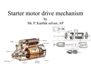
  • 1. Starter motor drive mechanism by Mr. P. Karthik selvan, AP
  • 2. • The starting motor is located near the flywheel .The drive gear on the starter is arranged so that it can mesh with the teeth on the flywheel (or the ring gear) when the starting switch is closed. • The drive mechanism has two functions: (1) To transmit the turning force to the engine when the starting motor runs and to disconnect the starting motor from the engine immediately after the engine has started and (2) To provide a gear reduction ratio between the starting motor and the engine. (The gear ratio between the driven pinion and the flywheel is usually about 15 to 1. This means that the starting motor rotates 15 times as fast as the engine, or at 1500 rpm to turn the engine at a speed of 100 rpm.)
  • 3. • The drive mechanism must disengage the pinion from the flywheel immediately after the engine starts. • After the engine starts, the engine speed may increase rapidly to approximately 1500 rpm. • If the drive pinion were to remain meshed with the flywheel and locked with the shaft of the starting motor, at a normal engine speed (1500 rpm), the shaft would spin at a rapid rate of speed (between 22,500 and 30,000 rpm). At such a rate of speed, the starting motor would be badly damaged.
  • 4. Types of starter drives The common kinds of starter drives used are: 1. Bendix drive (Inertia drive) 2. Improved Inertia type 3. Bendix folo-thru type 4. Pre-engagement drive 5. Sliding armature with overrunning type (Axial type) 6. Permanent magnet type. All of these starter drives use a one-way clutch (overrunning clutch) to release the starter drive pinion from the flywheel after the engine has started
  • 5. Bendix drive (Inertia drive) • A Bendix drive is a type of engagement mechanism used in a starter motors of internal combustion engines • Inertia type drive works on the principle of inertia of unbalanced weight. In this type, pinion is mounted on threaded sleeve • Engage- When ignition switch pressed, the starter motor begins turning, the inertia of the drive pinion assembly causes it to wound the spring, forcing the length of the spring to change and engage with the ring gear • Disengage- When the engine starts, back drive from the ring gear causes the drive pinion to exceed the rotation speed of the starter, at which point the drive pinion is forced back and out of the mesh with the ring gear • Spring – To pull back the assembly, To avoid hitting of ring gear against the casing
  • 6.
  • 7. • Disadvantage • Lots of moving parts cause rapid wearing of teeth • Engagement of pinion is done after starter motor starts To overcome this, pinion must be engaged before starter motor rotating. As a result, pre-engage drive is developed. • Application- old vehicles
  • 8. Pre Engagement type • This has a solenoid or magnetic switch which is used to shift the drive pinion magnetically into mesh with the engine flywheel complete the circuit between the battery and self starter • In this arrangement the drive pinion on the starter motor shaft is pushed axially into mesh with the flywheel ring gear before the starter motor is switched ON • When the pinion meshes with flywheel ring gear, the starter motor is switched ON by engagement relay • A solenoid is usually employed to move the lever and close the switch contacts. This method is quite simple and having the advantage not to damage gear teeth
  • 9. • Engage- When we turn the key to start solenoid switch ON, the starter motor shifts the pinion with the help of lever for the engagement with ring gear • As the engine is started, it is the time to disengage the pinion form the flywheel • Disengage- This is done by the overrunning clutch which is attached to a pinion overrunning clutch make the pinion free from the starter motor shaft as the engine starts. And motor is saved from the high speed damage Advantage - * A smaller pinion can be utilized for higher reduction * Pinion drive is not so highly stressed * Prolonged cranking life Application – Car and medium size vehicles
  • 10.
  • 11.
  • 12. Axial or sliding armature type • The axial starter works on the principle of a sliding armature mechanism • It is similar like pre-engagement drive, In pre engagement type ring gear only moves forward and backward but in this axial armature type whole armature unit will moves forward and backward to produced high starting torque • Here, when the starter switch is operated a solenoid coil is energized. • This completed the circuit of a shunt winding and also of an auxiliary, series field winding • It consists of two winding- one for energizing and another one for moving the armature or sliding
  • 13. • The armature is drawn into a central position in addition to rotating because of the magnetic field • As the pinion is attached to the armature shaft, it is moved axially and gets engaged with the flywheel ring gear • After the complete engagement of the pinion with the flywheel ring gear, a catch on the switch is tripped, thereby emerging the main series winding and marking the motor to operate on its full power current supply • A slipping clutch is provided between the pinion and the armature to avoid over speed of the motor
  • 14.
  • 15. OVERRUNNING CLUTCH • The overrunning clutch is roller-type clutch that transmits torque in one direction only and freewheels in the other direction • This allows the starter motor to transmit torque to the ring gear but prevents the ring gear from transferring torque to the starter motor • In a typical overrunning type clutch, the clutch housing is internally splined to the starter armature shaft • The drive pinion turns freely on the armature shaft within the clutch housing
  • 16. • When torque is transmitted through the armature to the clutch housing, the spring loaded rollers are forced into the small ends of their tapered slots • They are then wedged tightly against the pinion barrel • The pinion barrel and clutch housing are now locked together, torque is transferred through the starter motor to the ring gear and engine • This unloads the clutch rollers and releases the pinion gear to rotate freely around the armature shaft
  • 17.
  • 18. SHUNT MOTOR SERIES MOTOR Field winding connected parallel with armature Filed winding connected series with armature Shunt motor are parallel and hence low current Series motor are series so high armature current Shunt DC Motor is used in constant torque application Series DC Motor is used for high starting torque application