SlideShare a Scribd company logo
1 of 6
When an emf is applied to an inductor the current cannot rise instantaneously
due to the emf generated by the coil (back emf, ‘e’) which opposes the flow
of current.
Transients - Inductive Circuits
At the instant the voltage is
applied, i = 0
At any instant:
e
iR
-
S
V
+
R
L
I
or
V = e + iR
also induced emf ‘e’
di
dt
e = V – iR = L
=
di
dt
V
L
A/s
initial rate of change in current
dt
di
V = L
V = iR + L
di
dt
final current
Io =
V
R
final current
rate of change of current
=
L
R
seconds=
V/L
V/R
The time constant, T =
As the current rises in an inductance, the back emf opposes the supply voltage and
causes the rate of rise in current to reduce as time goes on. After approximately 5 time
constants the current is within 1% of its maximum value.
Transients - Inductive Circuits
If the current continued to rise at its initial rate, it would reach its maximum value in
one time constant (T) seconds.
Initial rate of rise of current, di/dt = VS / L A/s
Maximum current possible, I = VS / R A
Current rise at any instant, i = I(1 – e – Rt /L
) V
I=VS /R
T
( L/R)
0 20 40 60 80 t (msec)
2.0
1.5
1.0
0.5
0
-
S
VS 100V
+
R = 50Ω
L 800 mH
I
If the source emf is removed and the inductor is short circuited the energy stored in the
magnetic field will collapse. The current cannot fall immediately to zero as the collapse
is opposed by the self induced emf which tries to maintain the current at its original
value.
Transients - Inductive Circuits
After 5 time constants the current is said to have reached its final value although
the equation allows for a continuously decaying state.
Initial rate of decay of current, di/dt = -VL / L A/s
Initial current possible, I = VL / R
Current decay at any instant, i = Ie – Rt /L
I=VS /R
T
( L/R)
0 20 40 60 80 t (msec)
2.0
1.5
1.0
0.5
0
-
+
R = 50Ω
L 800 mH
I
Transients – Inductive Circuits
Activity
1. A 200mH inductor is connected to a 20V dc supply. If the coil
resistance is 10Ω, determine a) the time constant, b) the initial rate of
increase in current, c) the time to reach a fully charged state and d) the
current at t = L/R s.
2. A coil of inductance 0.5H and resistance 25Ω is suddenly connected to
a 100V supply. Find a) the current after 5 seconds, b) the time at which
vL = vR and c) the final steady state current.
3. A coil of resistance 20Ω and inductance 250mH is connected to a 40V
dc supply and the current is allowed to reach its final steady state after
which the supply is removed and the coil instantly short circuited.
Calculate a) the initial rate of decrease of current and b) the current
after L/R seconds and c) the time for the current to be reduced by 20%.
What Have We Learnt
The time constant for a LR network is T = LR seconds and after 5LR seconds
the capacitor is fully charged or discharged.
The rate of change of current is continuously opposed by the induced emf
(back emf) in the coil.
0
10
20
30
40
50
60
70
80
90
100
110
120
0
29
59
88
118
147
176
206
235
265
294
324
353
382
412
441
471
500
t
i
I
0
1
2
3
4
5
6
7
8
9
10
0
59
118
176
235
294
353
412
471
I
t
i
The decaying current (i) at any instant in time can be found using the formula
i = Io e – Rt /L
The rising current (i) at any instant in time can be found using the formula
i = Io (1 – e -R t /L
)

More Related Content

What's hot

Implementation of Cascaded H-bridge MULTI-LEVEL INVERTER
Implementation of Cascaded H-bridge MULTI-LEVEL INVERTERImplementation of Cascaded H-bridge MULTI-LEVEL INVERTER
Implementation of Cascaded H-bridge MULTI-LEVEL INVERTEREditor IJMTER
 
Dc circuits
Dc circuitsDc circuits
Dc circuitsEkeeda
 
V/F control of Induction Motor - Variable voltage and Variable frequency
V/F control of Induction Motor - Variable voltage and Variable frequencyV/F control of Induction Motor - Variable voltage and Variable frequency
V/F control of Induction Motor - Variable voltage and Variable frequencyCitharthan Durairaj
 
Lab 4 Report Switching Voltage Regulators
Lab 4 Report Switching Voltage Regulators Lab 4 Report Switching Voltage Regulators
Lab 4 Report Switching Voltage Regulators Katrina Little
 
Three phase voltage source inverter
Three phase voltage source inverterThree phase voltage source inverter
Three phase voltage source invertertamilnesaner
 
Hybrid Transistor Model with Two Port Network
Hybrid Transistor Model with Two Port NetworkHybrid Transistor Model with Two Port Network
Hybrid Transistor Model with Two Port NetworkRidwanul Hoque
 
Power System Modelling And Simulation Lab
Power System Modelling And Simulation LabPower System Modelling And Simulation Lab
Power System Modelling And Simulation LabSachin Airan
 
Ee2203 electronic-devices-and-circuits-lecture-notes
Ee2203 electronic-devices-and-circuits-lecture-notesEe2203 electronic-devices-and-circuits-lecture-notes
Ee2203 electronic-devices-and-circuits-lecture-notesdrmbalu
 
Multilevel inverter
Multilevel inverterMultilevel inverter
Multilevel inverterak dixit
 

What's hot (20)

Implementation of Cascaded H-bridge MULTI-LEVEL INVERTER
Implementation of Cascaded H-bridge MULTI-LEVEL INVERTERImplementation of Cascaded H-bridge MULTI-LEVEL INVERTER
Implementation of Cascaded H-bridge MULTI-LEVEL INVERTER
 
Dc circuits
Dc circuitsDc circuits
Dc circuits
 
Unit 3
Unit 3Unit 3
Unit 3
 
Unit 1 graph theory
Unit 1 graph theoryUnit 1 graph theory
Unit 1 graph theory
 
Ch12 ln
Ch12 lnCh12 ln
Ch12 ln
 
V/F control of Induction Motor - Variable voltage and Variable frequency
V/F control of Induction Motor - Variable voltage and Variable frequencyV/F control of Induction Motor - Variable voltage and Variable frequency
V/F control of Induction Motor - Variable voltage and Variable frequency
 
Lab 4 Report Switching Voltage Regulators
Lab 4 Report Switching Voltage Regulators Lab 4 Report Switching Voltage Regulators
Lab 4 Report Switching Voltage Regulators
 
Armature reaction
Armature reactionArmature reaction
Armature reaction
 
Three phase voltage source inverter
Three phase voltage source inverterThree phase voltage source inverter
Three phase voltage source inverter
 
Transformer 2
Transformer 2Transformer 2
Transformer 2
 
Hybrid Transistor Model with Two Port Network
Hybrid Transistor Model with Two Port NetworkHybrid Transistor Model with Two Port Network
Hybrid Transistor Model with Two Port Network
 
Power System Modelling And Simulation Lab
Power System Modelling And Simulation LabPower System Modelling And Simulation Lab
Power System Modelling And Simulation Lab
 
Per unit system
Per unit systemPer unit system
Per unit system
 
Dc machines ppt
Dc machines pptDc machines ppt
Dc machines ppt
 
Electrical Network Topology
Electrical Network TopologyElectrical Network Topology
Electrical Network Topology
 
Inverter
InverterInverter
Inverter
 
Series ac circuit
Series ac circuitSeries ac circuit
Series ac circuit
 
Per unit analysis
Per unit analysisPer unit analysis
Per unit analysis
 
Ee2203 electronic-devices-and-circuits-lecture-notes
Ee2203 electronic-devices-and-circuits-lecture-notesEe2203 electronic-devices-and-circuits-lecture-notes
Ee2203 electronic-devices-and-circuits-lecture-notes
 
Multilevel inverter
Multilevel inverterMultilevel inverter
Multilevel inverter
 

Viewers also liked

Elect principles 2 dc transients (capacitive)
Elect principles 2   dc transients (capacitive)Elect principles 2   dc transients (capacitive)
Elect principles 2 dc transients (capacitive)sdacey
 
Elect principles 2 current divider
Elect principles 2   current dividerElect principles 2   current divider
Elect principles 2 current dividersdacey
 
Elect principles 2 ac circuits parallel
Elect principles 2   ac circuits parallelElect principles 2   ac circuits parallel
Elect principles 2 ac circuits parallelsdacey
 
Elect principles 2 nortons theorem
Elect principles 2   nortons theoremElect principles 2   nortons theorem
Elect principles 2 nortons theoremsdacey
 
Elect principles 2 ac circuits (rl)
Elect principles 2   ac circuits (rl)Elect principles 2   ac circuits (rl)
Elect principles 2 ac circuits (rl)sdacey
 
Basic concept of circuit theory
Basic concept of circuit theoryBasic concept of circuit theory
Basic concept of circuit theoryelectrodictionteam
 
Elect principles 2 voltage divider
Elect principles 2   voltage dividerElect principles 2   voltage divider
Elect principles 2 voltage dividersdacey
 

Viewers also liked (7)

Elect principles 2 dc transients (capacitive)
Elect principles 2   dc transients (capacitive)Elect principles 2   dc transients (capacitive)
Elect principles 2 dc transients (capacitive)
 
Elect principles 2 current divider
Elect principles 2   current dividerElect principles 2   current divider
Elect principles 2 current divider
 
Elect principles 2 ac circuits parallel
Elect principles 2   ac circuits parallelElect principles 2   ac circuits parallel
Elect principles 2 ac circuits parallel
 
Elect principles 2 nortons theorem
Elect principles 2   nortons theoremElect principles 2   nortons theorem
Elect principles 2 nortons theorem
 
Elect principles 2 ac circuits (rl)
Elect principles 2   ac circuits (rl)Elect principles 2   ac circuits (rl)
Elect principles 2 ac circuits (rl)
 
Basic concept of circuit theory
Basic concept of circuit theoryBasic concept of circuit theory
Basic concept of circuit theory
 
Elect principles 2 voltage divider
Elect principles 2   voltage dividerElect principles 2   voltage divider
Elect principles 2 voltage divider
 

Similar to Elect principles 2 dc transients (inductive)

9780750687478.pdf
9780750687478.pdf9780750687478.pdf
9780750687478.pdfalice145466
 
Transients analysis and Its derivations
Transients  analysis and Its derivations Transients  analysis and Its derivations
Transients analysis and Its derivations Haseeb Memon
 
controlled Full Bridge Rectifier
controlled Full Bridge Rectifiercontrolled Full Bridge Rectifier
controlled Full Bridge RectifierJen Trần
 
applications of differential equations in RL-RC electrical circuit problems
applications of differential equations in RL-RC electrical circuit problemsapplications of differential equations in RL-RC electrical circuit problems
applications of differential equations in RL-RC electrical circuit problemsOmmPrakashMishra
 
Current & Ohms Law 03 2000
Current & Ohms Law 03 2000Current & Ohms Law 03 2000
Current & Ohms Law 03 2000mistertee
 
Electrical Engineering
Electrical EngineeringElectrical Engineering
Electrical EngineeringEkeeda
 
Transient in Power system
Transient in Power systemTransient in Power system
Transient in Power systemPreet_patel
 
Basic electronic book of BSCS first semester
Basic electronic book of BSCS first semesterBasic electronic book of BSCS first semester
Basic electronic book of BSCS first semestergiyoleg464
 
4.alternating_currents.ppt
4.alternating_currents.ppt4.alternating_currents.ppt
4.alternating_currents.pptGaneshsaini17
 
2_ALTERNATING_CURRENTS.ppt
2_ALTERNATING_CURRENTS.ppt2_ALTERNATING_CURRENTS.ppt
2_ALTERNATING_CURRENTS.pptReeve2
 
4.alternating_currents (1).ppt
4.alternating_currents (1).ppt4.alternating_currents (1).ppt
4.alternating_currents (1).pptGaneshsaini17
 
2_alternating_currents (2).pptx
2_alternating_currents (2).pptx2_alternating_currents (2).pptx
2_alternating_currents (2).pptxADITYARAJSINGH11A
 
2_alternating_currents.ppt
2_alternating_currents.ppt2_alternating_currents.ppt
2_alternating_currents.pptmragarwal
 
Lecture 27 inductors. stored energy. lr circuits
Lecture 27  inductors. stored energy. lr circuitsLecture 27  inductors. stored energy. lr circuits
Lecture 27 inductors. stored energy. lr circuitsAlbania Energy Association
 

Similar to Elect principles 2 dc transients (inductive) (20)

ac slides type 1.pdf
ac slides type 1.pdfac slides type 1.pdf
ac slides type 1.pdf
 
9780750687478.pdf
9780750687478.pdf9780750687478.pdf
9780750687478.pdf
 
Transients analysis and Its derivations
Transients  analysis and Its derivations Transients  analysis and Its derivations
Transients analysis and Its derivations
 
TRANSIENT IN POWER SYSTEM
TRANSIENT IN POWER SYSTEMTRANSIENT IN POWER SYSTEM
TRANSIENT IN POWER SYSTEM
 
controlled Full Bridge Rectifier
controlled Full Bridge Rectifiercontrolled Full Bridge Rectifier
controlled Full Bridge Rectifier
 
applications of differential equations in RL-RC electrical circuit problems
applications of differential equations in RL-RC electrical circuit problemsapplications of differential equations in RL-RC electrical circuit problems
applications of differential equations in RL-RC electrical circuit problems
 
Transformer
TransformerTransformer
Transformer
 
Transformers
TransformersTransformers
Transformers
 
Current & Ohms Law 03 2000
Current & Ohms Law 03 2000Current & Ohms Law 03 2000
Current & Ohms Law 03 2000
 
ec ppt
ec pptec ppt
ec ppt
 
Electrical Engineering
Electrical EngineeringElectrical Engineering
Electrical Engineering
 
Transient in Power system
Transient in Power systemTransient in Power system
Transient in Power system
 
Basic electronic book of BSCS first semester
Basic electronic book of BSCS first semesterBasic electronic book of BSCS first semester
Basic electronic book of BSCS first semester
 
Chapter32A.ppt
Chapter32A.pptChapter32A.ppt
Chapter32A.ppt
 
4.alternating_currents.ppt
4.alternating_currents.ppt4.alternating_currents.ppt
4.alternating_currents.ppt
 
2_ALTERNATING_CURRENTS.ppt
2_ALTERNATING_CURRENTS.ppt2_ALTERNATING_CURRENTS.ppt
2_ALTERNATING_CURRENTS.ppt
 
4.alternating_currents (1).ppt
4.alternating_currents (1).ppt4.alternating_currents (1).ppt
4.alternating_currents (1).ppt
 
2_alternating_currents (2).pptx
2_alternating_currents (2).pptx2_alternating_currents (2).pptx
2_alternating_currents (2).pptx
 
2_alternating_currents.ppt
2_alternating_currents.ppt2_alternating_currents.ppt
2_alternating_currents.ppt
 
Lecture 27 inductors. stored energy. lr circuits
Lecture 27  inductors. stored energy. lr circuitsLecture 27  inductors. stored energy. lr circuits
Lecture 27 inductors. stored energy. lr circuits
 

More from sdacey

Elect principles 2 three phase systems
Elect principles 2   three phase systemsElect principles 2   three phase systems
Elect principles 2 three phase systemssdacey
 
Elect principles 2 ac circuits series resonance
Elect principles 2   ac circuits series resonanceElect principles 2   ac circuits series resonance
Elect principles 2 ac circuits series resonancesdacey
 
Elect principles 2 filter networks
Elect principles 2   filter networksElect principles 2   filter networks
Elect principles 2 filter networkssdacey
 
Elect principles 2 three phase systems
Elect principles 2   three phase systemsElect principles 2   three phase systems
Elect principles 2 three phase systemssdacey
 
Elect principles 2 power in ac circuits
Elect principles 2   power in ac circuitsElect principles 2   power in ac circuits
Elect principles 2 power in ac circuitssdacey
 
Elect principles 2 filter networks
Elect principles 2   filter networksElect principles 2   filter networks
Elect principles 2 filter networkssdacey
 
Elect principles 2 power factor
Elect principles 2   power factorElect principles 2   power factor
Elect principles 2 power factorsdacey
 
Elect principles 2 max power transfer
Elect principles 2   max power transferElect principles 2   max power transfer
Elect principles 2 max power transfersdacey
 
Elect principles 2 thevenin theorem
Elect principles 2   thevenin theoremElect principles 2   thevenin theorem
Elect principles 2 thevenin theoremsdacey
 
Electronics power supplies
Electronics   power suppliesElectronics   power supplies
Electronics power suppliessdacey
 
Machines the dc motor
Machines   the dc motorMachines   the dc motor
Machines the dc motorsdacey
 
Components the transformer
Components   the transformerComponents   the transformer
Components the transformersdacey
 
Elect principles -_resistance
Elect principles -_resistanceElect principles -_resistance
Elect principles -_resistancesdacey
 
Elect principles -_ac_circuits_year1
Elect principles -_ac_circuits_year1Elect principles -_ac_circuits_year1
Elect principles -_ac_circuits_year1sdacey
 
Elect principles -_ac_waveform_year1
Elect principles -_ac_waveform_year1Elect principles -_ac_waveform_year1
Elect principles -_ac_waveform_year1sdacey
 
Components the diode
Components   the diodeComponents   the diode
Components the diodesdacey
 
Elect principles -_capacitance
Elect principles -_capacitanceElect principles -_capacitance
Elect principles -_capacitancesdacey
 
Elect principles -_kirchhoffs_laws
Elect principles -_kirchhoffs_lawsElect principles -_kirchhoffs_laws
Elect principles -_kirchhoffs_lawssdacey
 

More from sdacey (18)

Elect principles 2 three phase systems
Elect principles 2   three phase systemsElect principles 2   three phase systems
Elect principles 2 three phase systems
 
Elect principles 2 ac circuits series resonance
Elect principles 2   ac circuits series resonanceElect principles 2   ac circuits series resonance
Elect principles 2 ac circuits series resonance
 
Elect principles 2 filter networks
Elect principles 2   filter networksElect principles 2   filter networks
Elect principles 2 filter networks
 
Elect principles 2 three phase systems
Elect principles 2   three phase systemsElect principles 2   three phase systems
Elect principles 2 three phase systems
 
Elect principles 2 power in ac circuits
Elect principles 2   power in ac circuitsElect principles 2   power in ac circuits
Elect principles 2 power in ac circuits
 
Elect principles 2 filter networks
Elect principles 2   filter networksElect principles 2   filter networks
Elect principles 2 filter networks
 
Elect principles 2 power factor
Elect principles 2   power factorElect principles 2   power factor
Elect principles 2 power factor
 
Elect principles 2 max power transfer
Elect principles 2   max power transferElect principles 2   max power transfer
Elect principles 2 max power transfer
 
Elect principles 2 thevenin theorem
Elect principles 2   thevenin theoremElect principles 2   thevenin theorem
Elect principles 2 thevenin theorem
 
Electronics power supplies
Electronics   power suppliesElectronics   power supplies
Electronics power supplies
 
Machines the dc motor
Machines   the dc motorMachines   the dc motor
Machines the dc motor
 
Components the transformer
Components   the transformerComponents   the transformer
Components the transformer
 
Elect principles -_resistance
Elect principles -_resistanceElect principles -_resistance
Elect principles -_resistance
 
Elect principles -_ac_circuits_year1
Elect principles -_ac_circuits_year1Elect principles -_ac_circuits_year1
Elect principles -_ac_circuits_year1
 
Elect principles -_ac_waveform_year1
Elect principles -_ac_waveform_year1Elect principles -_ac_waveform_year1
Elect principles -_ac_waveform_year1
 
Components the diode
Components   the diodeComponents   the diode
Components the diode
 
Elect principles -_capacitance
Elect principles -_capacitanceElect principles -_capacitance
Elect principles -_capacitance
 
Elect principles -_kirchhoffs_laws
Elect principles -_kirchhoffs_lawsElect principles -_kirchhoffs_laws
Elect principles -_kirchhoffs_laws
 

Elect principles 2 dc transients (inductive)

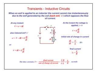
  • 1. When an emf is applied to an inductor the current cannot rise instantaneously due to the emf generated by the coil (back emf, ‘e’) which opposes the flow of current. Transients - Inductive Circuits At the instant the voltage is applied, i = 0 At any instant: e iR - S V + R L I or V = e + iR also induced emf ‘e’ di dt e = V – iR = L = di dt V L A/s initial rate of change in current dt di V = L V = iR + L di dt final current Io = V R final current rate of change of current = L R seconds= V/L V/R The time constant, T =
  • 2. As the current rises in an inductance, the back emf opposes the supply voltage and causes the rate of rise in current to reduce as time goes on. After approximately 5 time constants the current is within 1% of its maximum value. Transients - Inductive Circuits If the current continued to rise at its initial rate, it would reach its maximum value in one time constant (T) seconds. Initial rate of rise of current, di/dt = VS / L A/s Maximum current possible, I = VS / R A Current rise at any instant, i = I(1 – e – Rt /L ) V I=VS /R T ( L/R) 0 20 40 60 80 t (msec) 2.0 1.5 1.0 0.5 0 - S VS 100V + R = 50Ω L 800 mH I
  • 3. If the source emf is removed and the inductor is short circuited the energy stored in the magnetic field will collapse. The current cannot fall immediately to zero as the collapse is opposed by the self induced emf which tries to maintain the current at its original value. Transients - Inductive Circuits After 5 time constants the current is said to have reached its final value although the equation allows for a continuously decaying state. Initial rate of decay of current, di/dt = -VL / L A/s Initial current possible, I = VL / R Current decay at any instant, i = Ie – Rt /L I=VS /R T ( L/R) 0 20 40 60 80 t (msec) 2.0 1.5 1.0 0.5 0 - + R = 50Ω L 800 mH I
  • 4. Transients – Inductive Circuits Activity 1. A 200mH inductor is connected to a 20V dc supply. If the coil resistance is 10Ω, determine a) the time constant, b) the initial rate of increase in current, c) the time to reach a fully charged state and d) the current at t = L/R s. 2. A coil of inductance 0.5H and resistance 25Ω is suddenly connected to a 100V supply. Find a) the current after 5 seconds, b) the time at which vL = vR and c) the final steady state current. 3. A coil of resistance 20Ω and inductance 250mH is connected to a 40V dc supply and the current is allowed to reach its final steady state after which the supply is removed and the coil instantly short circuited. Calculate a) the initial rate of decrease of current and b) the current after L/R seconds and c) the time for the current to be reduced by 20%.
  • 5. What Have We Learnt The time constant for a LR network is T = LR seconds and after 5LR seconds the capacitor is fully charged or discharged. The rate of change of current is continuously opposed by the induced emf (back emf) in the coil. 0 10 20 30 40 50 60 70 80 90 100 110 120 0 29 59 88 118 147 176 206 235 265 294 324 353 382 412 441 471 500 t i I 0 1 2 3 4 5 6 7 8 9 10 0 59 118 176 235 294 353 412 471 I t i The decaying current (i) at any instant in time can be found using the formula i = Io e – Rt /L The rising current (i) at any instant in time can be found using the formula i = Io (1 – e -R t /L )
  • 6. What Have We Learnt The time constant for a LR network is T = LR seconds and after 5LR seconds the capacitor is fully charged or discharged. The rate of change of current is continuously opposed by the induced emf (back emf) in the coil. 0 10 20 30 40 50 60 70 80 90 100 110 120 0 29 59 88 118 147 176 206 235 265 294 324 353 382 412 441 471 500 t i I 0 1 2 3 4 5 6 7 8 9 10 0 59 118 176 235 294 353 412 471 I t i The decaying current (i) at any instant in time can be found using the formula i = Io e – Rt /L The rising current (i) at any instant in time can be found using the formula i = Io (1 – e -R t /L )