SlideShare a Scribd company logo
1 of 34
Download to read offline
MCC Ratings


                 In addition to the various ratings of individual components used
                 in motor control centers, the overall ratings of the motor control
                 center must also be considered.

Voltage Rating   Motor control centers are rated for 600 volts. This is the
                 maximum voltage that can be applied to a motor control center.
                 A motor control center can be connected to a lower voltage.
                 A motor control center, for example, might be connected to a
                 three-phase, 480 VAC power supply.


Horizontal Bus   The horizontal bus on Siemens motor control centers are made
Current Rating   of tin or optional silver plated copper. They are available with
                 600A, 800A, 1200A, 1600A, and 2000A current ratings.


                                                                                 47
Vertical Bus   The vertical bus on the TIASTAR motor control centers are
               available with 300A and 600A ratings.


Bus Bracing    Motor control centers must be capable of withstanding the
               largest potential short-circuit current which can occur in the
               selected application. The amount of short-circuit current
               available depends on the amount of power available to a facility.
               Short-circuit current can be thousands of times higher than
               normal current. Bus bars must be braced to withstand this
               potential current. Siemens bus bars are braced for 42,000 AIC
               (ampere interrupting capacity) with optional bracing available to
               100,000 AIC.


48
Temperature Rise   The bus bars are the major current carrying component of the
                   motor control center. Before a motor control center is operated,
                   bus bars are at the temperature of the surrounding air. This is
                   known as ambient temperature. Temperature rises in the motor
                   control center bus bars during operation. The combination of
                   ambient temperature and allowed temperature rise equals the
                   maximum temperature of the bus bars.

                   NEMA and UL both have standards concerning the maximum
                   temperature rise of bus bars used in motor control centers.
                   NEMA limits temperature rise to 65°C based on an ambient
                   temperature of 40°C (104°F), for a maximum operating
                   temperature of 105°C. UL limits temperature rise to 50°C based
                   on an ambient temperature of 40°C (104°F), for a maximum
                   operating temperature of 90°C. Electrical equipment bearing a
                   UL mark must meet or exceed this standard.

                   Siemens motor control centers meet or exceed NEMA and
                   UL standards. Bus bars in Siemens motor control centers are
                   tested with a maximum temperature rise of 50°C over 40°C
                   (104°F) ambient.


                                                                                 49
Enclosures


                   NEMA defines an enclosure as a surrounding case constructed
                   to provide a degree of protection to personnel against incidental
                   contact with the enclosed equipment and to provide a degree
                   of protection to the enclosed equipment against specified
                   environmental conditions (NEMA Standard 250 - section 2,
                   definitions).

                   The following brief descriptions cover enclosures available for
                   Siemens motor control centers.

Type 1 Enclosure   Type 1 enclosures are intended for indoor use primarily to
                   provide protection against limited amounts of falling dirt and
                   contact with the enclosed equipment in locations where
                   unusual service conditions do not exist.


50
Type 1 Gasket Front   Type 1 gasketed front, general purpose, indoor enclosure has
                      the same use as Type 1 except the front of the enclosure is
                      gasketed. In addition the following parts are gasketed:

                      Unit separator angles
                      Right-hand side of front of units
                      Bottom horizontal cross ties
                      Lip on top plate
                      Pilot-device panel
                      Handle mechanism
                      Bottom horizontal wireway cover plate
                      Side holes are plugged

Type 2, Drip-Proof    Type 2, drip-proof is an indoor enclosure intended to protect
                      equipment from falling noncorrosive liquids and dirt. The
                      enclosure prevents the entrance of dripping liquid at a higher
                      level than the lowest live part within the enclosure. This
                      design is a Type 1 gasketed front, or Type 12, with a drip shield
                      mounted on top of the enclosure.

Type 12 Enclosure     Type 12 enclosures are intended for indoor use primarily to
                      provide a degree of protection against circulating dust, falling
                      dirt, and dripping noncorrosive liquids. They are not intended
                      to provide protection against conditions such as internal
                      condensation.

                      The Type 12 will provide a greater degree of protection than a
                      Type 1 gasketed enclosure. The following additional parts are
                      gasketed:

                      Hinged side of doors
                      Top plates
                      Wireway end-covers
                      Rear plates

                      There is no gap between sections, allowing for much greater
                      dust resistance. In addition, interconnection holes in the side
                      sheet assemblies are sealed. Bottom plates are included.


                                                                                         51
Type 3R Enclosure   Type 3R enclosures are intended for outdoor use primarily to
                    provide a degree of protection against falling rain and sleet and
                    protection from contact with the enclosed equipment. They are
                    not dust, snow, or sleet (ice) proof. They will prevent entrance of
                    rain at a level higher than the lowest live part. The enclosure has
                    provisions for locking and drainage.


                    The enclosure entirely surrounds the motor control center
                    for outdoor operation. The Type 3R enclosure is designed
                    to accommodate bottom cable entry and exit only. The 3R
                    enclosure is not a walk-in type design.


NEMA and IEC        The International Electrotechnical Commission (IEC) is another
                    organization that defines the degree of protection provided by
                    enclosures. NEMA is primarily associated with equipment used
                    in North America. IEC is associated with equipment sold in
                    many countries including the United States.

                    The IEC designation consists of the letters IP followed by two
                    numbers. The first number indicates the degree of protection
                    provided by the enclosure with respect to persons and solid
                    objects entering the enclosure. The second number indicates
                    the degree of protection against the ingress of water. The
                    following chart provides an equivalent conversion between
                    NEMA and IEC designations.

                    NEMA           IEC

                    1              IP10
                    2              IP11
                    3R             IP14
                    12             IP52


52
Classification and Types of Wiring


                         NEMA has established two classification standards (Class I
                         and Class II) and three types of wiring (A, B, and C) used in the
                         construction of motor control centers. These are specified by
                         the customer.

Class I                  Class I consists of a grouping of combination motor control
                         units in which each starter and motor operates independently
                         of the other starters. The factory connects the combination
                         motor control units to the vertical bus but does not provide
                         interconnecting wiring between combination motor control
                         units, different vertical units, or remotely connected devices.
                         Diagrams of the individual units only are supplied.

Class I, Type A Wiring   Type A wiring is only available on Class I motor control
                         centers. The motor control center manufacturer connects the
                         combination motor control unit to the vertical bus via the stabs
                         on the back of the unit. Power is applied to the circuit breaker
                         from the vertical bus. The circuit breaker is factory wired to
                         the motor starter. The customer connects the motor leads and
                         control wiring to the motor starter. There is no interconnecting
                         wiring between combination motor control units.


                                                                                           53
Class I, Type B Wiring   Typically pilot devices, such as indicator lights, pushbuttons, and
                         selector switches, are used with Class I, Type B wiring. Type B
                         wiring is divided into two designations: B-d (-d for connection
                         of load wires directly on starter or contactor terminals) and B-t
                         (-t for connection of load wires to unit mounted load terminal
                         blocks).

                         When Type B-d wiring is specified, terminal blocks are furnished
                         near the wireway for control circuit connections. Motor leads
                         are connected directly to the overload relay terminals.


                         When Type B-t wiring is specified, terminal blocks are furnished
                         near the wireway for control circuit connections and for motor
                         starter leads. Type B-t wiring can be used on starters up to
                         size 3.


54
Class I, Type C Wiring   With Type C wiring, a master terminal block is provided in either
                         the top or bottom horizontal wiring gutter. The manufacturer
                         of the motor control center brings the control wires from each
                         control unit to the master terminal block. The installer is then
                         able to make his wiring connections at the master terminal
                         block. With Type C wiring, load wiring for combination motor
                         control units smaller than size 3 (50 HP) are connected to
                         the master terminal block. Load wiring for combination motor
                         control units larger than size 3 are connected directly to unit
                         device terminals..


                                                                                       55
Class II           Class II consists of a grouping of combination motor control
                   units with interwiring and interlocking between the starters to
                   form a complete control system. Wiring diagrams, including
                   the interwiring, is furnished. Class II is generally specified
                   when a group of motors requires sequencing, interlocking, or
                   interconnecting.

Class II, Type B   Class II, Type B wiring is similar to Class I, Type B wiring.
                   Terminal blocks are furnished near the wireway. In addition,
                   Class II, Type B wiring includes interconnecting wiring between
                   motor starters.


56
Class II, Type C   Class II, Type C wiring is similar to Class I, Type C wiring. In
                   addition, Class II, Type C wiring includes interconnecting wiring
                   between motor starters and vertical sections.


Reference Chart    The following chart provides a handy reference when
                   determining the class and type of wiring used in motor control
                   centers.


                                                                                  57
Cable Entry


            There are several ways incoming power can be terminated
            in a motor control center. Cable can be routed directly to the
            incoming power lugs, to main breakers or disconnects, or to a
            terminal block in a vertical section. In addition, incoming power
            cables can enter and exit the motor control center from the top
            or bottom depending on the application.

Main Lugs   When using main lugs the amount of vertical space required
            varies with the amperage rating. When the main lugs are
            located on the top, as in the following illustration, the vertical
            space is taken at the top. A motor control center can also have
            the lugs located at the bottom of the MCC. In the following
            illustration, for example, main lugs rated for 600 amps are
            located on the top of the MCC. In this example 24” of vertical
            space is required.


58
Main Lugs on Top,      In the arrangement illustrated below incoming power cables
Top Entry              enter through the top of a vertical section and are connected to
                       main lugs.


Main Lugs on Top,      Incoming cables can also enter from the bottom and connect to
Bottom Entry           main lugs located in the top section.


Main Lugs on Bottom,   Lugs can also be supplied on the bottom of the vertical bus for
Bottom Cable Entry     bottom cable entry.


                                                                                     59
Disconnect Device   When a main disconnect device, such as a circuit breaker
                    or fusible disconnect, is used, the disconnect is mounted in
                    its own unit. The amount of space required depends on the
                    disconnect used. The space can vary from 12” to 72” .


                    In the following illustration a main circuit breaker is used. Cable
                    entry can be from the top or bottom of the vertical section.


60
Review 5
           1.   The maximum current rating for a horizontal bus on
                Siemens motor control center is ____________ amps.

           2.   The maximum bus bracing available for a Siemens
                motor control center is ____________ AIC.

           3.   The IEC equivalent of a NEMA Type 3R enclosure is
                ____________ .

           4.   Identify the following types of Class I wiring:


                                                                     61
TIASTAR


     TIASTAR™ is trade name of the motor control centers that
     Siemens manufactures. Several mechanisms and features have
     been designed into TIASTAR. Many of these features will be
     discussed in this section.


62
Dimensions   The nominal height of TIASTAR is 90” high. The overall height
             is 91 1/8” including a standard 1 1/8” base channel. There are
             72” of vertical space available for combination motor control
             units, with 12” at the top and 6” at the bottom for wiring. The
             horizontal power bus is located in the 12” of top space making
             it easier to service. Each vertical unit will hold up to six 12” units
             (6 x 12 = 72). An optional pull box (top hat) can be supplied
             when extra wire-bending space is required. Pull boxes can be
             12” 18” or 24” high.
                 , ,

             Vertical structures are 20” wide. A 30” wide unit is available
             for special units, such as large AC drives or transformers that
             require more space. The vertical wireway is 4” wide on 20”
             wide sections. An optional 8”-wide wireway is available on 20”
             wide sections. Vertical units can be 15” or 20” deep.


                                                                                63
Back-to-Back Mounting   A feature of TIASTAR motor control centers is the ability to
                        mount combination motor control units back to back. This
                        permits mounting 12 combination motor control units in 72” of
                        vertical space. TIASTAR vertical units designed for back-to-back
                        mounting are 21” deep.


                        Back-to-back combination motor control units use the same
                        stab-on connection as front mounted units.


64
Basic Construction   TIASTAR motor control centers offer two vertical bus designs.
                     Front only structures with 42K or 65K bus bracing are supplied
                     with an insulated vertical bus design standard. The vertical bus
                     bars are not physically isolated phase-to-phase.

                     An optional isolated and insulated vertical bus assembly is
                     available for front only 42K and 65K bus bracing. The isolated
                     and insulated vertical bus design is standard for 100K bus
                     bracing and all back-to-back structures.

                     Combination motor control units can be interchanged and are
                     easily rearranged on either bus assembly. The unit support
                     brackets can be repositioned to accommodate various size
                     units.


                                                                                      65
Horizontal Bus   The horizontal bus is connected to the vertical bus with a
                 two-bolt, U-shaped clamp utilizing spring washers to maintain
                 torque. This allows the bolts to be tightened from the front.


                 Horizontal bus bars are shielded by a clear polycarbonate cover
                 for safety and easy visibility for inspection.


Ground Bus       A horizontal ground bus is mounted in the bottom 6” of space.
                 The horizontal ground bus is standard. An optional vertical
                 ground bus can be connected to the horizontal bus. When a
                 combination motor control unit is instered into the MCC the
                 vertical ground bus is the first item engaged. Likewise, when
                 the unit is removed the vertical ground bus is the last thing to
                 be disengaged.


66
Wire Tie Rods   Round wire tie rods are located in each vertical wireway to hold
                wire harnesses in place.


Pilot Devices   Pilot devices are mounted on a panel which latches onto the
                unit door with a simple tab-and-notch mechanism. The pilot-
                device panel can be removed from the door and attached to the
                combination motor control unit for service or unit removal. There
                is room for four 30mm pilot devices on the panel.


                                                                              67
Terminal Blocks    Terminal blocks are supplied with Type B and C wiring. The
                   terminal blocks are mounted up front on a swing-out side panel.
                   The panel is notched so that the terminal block can be placed
                   inside the unit, in a center position, or in the vertical wireway.
                   This secures the terminals inside the unit when access is not
                   required, or allows access from the vertical wireway. Pull-apart
                   terminals are available as an option.


Operating Handle   The disconnect operating handle has four positions. When
                   placed in the “PARK” position the unit door can be opened
                   without the handle interfering. The “TRIPPED” position is clearly
                   indicated.


68
Racking Lever   A racking lever located on each combination motor control unit
                is used to remove or install the unit. When the operator handle
                is in the “ON” position, a locking pin blocks the racking lever
                closed. When the operator handle is switched to the “OFF”
                position, the locking pin disengages the racking lever. The
                combination motor control unit can be pulled to a test position.
                The operator handle is placed in “PARK” to completely remove
                the combination motor control unit. The unit is designed so that
                it cannot be inserted or removed with the operator handle in the
                “ON” position. In the test position the unit can be padlocked in
                place.


Ground Clip     A copper clip on the side of the combination motor control unit
                engages the unit support bracket, grounding the unit to the
                motor control center at all times. An optional vertical bus stab is
                mounted on the unit when a vertical ground bus is used.


                                                                                69
Locking              The disconnect operating handle can be locked in the “OFF”
                     position with up to three padlocks.


High Density Units   TIASTAR is also available with high density units. High density
                     units are 6” tall. A maximum of 12 high density units can be
                     installed in 72” of vertical space. High density combination
                     motor control units are available in NEMA size 0 (5 HP) and
                     size 1 (10 HP). To compliment the high density unit, a 24”
                     wide structure is available with an oversized (8” wide) vertical
                     wireway. While the 24” wide structure allows for the increased
                     quantity of wires typical of high density applications, they are
                     not required when high density units are used.


70
Combination Units   High density units have many of the same features as the
                    full size units. The disconnect operating handle is mounted
                    sideways. When Type B or C wiring is specified, a swing-out
                    terminal block is supplied.

                    The motor starter is located behind the terminal block. The
                    circuit breaker is located behind the operator handle. A unique
                    “swing out” feature permits components to swing out of the
                    unit for easy inspection or maintenance.


                                                                                  71
Information Needed to Order MCCs


     When ordering a motor control center several questions need to
     be answered. The following information will be useful.

      •   Voltage, frequency, number of phases, and available
          fault current of power supply

      •   Incoming power requirements (main circuit breaker,
          main fusible switch, main lugs only, or splicing to
          existing MCC)

      •   Amp rating of the horizontal bus and finish material (tin
          or silver)

      •   Voltage rating and source of control power

      •   Size, type (aluminum or copper), number per phase and
          location of incoming cables or busway and outgoing
          cables

      •   Enclosure
          - Type, finish
          - Accessibility (front, rear, or both)
          - Clearance for door swing
          - Restrictions on height, width, and depth

      •   Horsepower rating and motor design of motors to be
          controlled

      •   Ampacity of feeder tap units and unit disconnect
          devices

      •   Type of disconnect for units: thermal-magnetic,
          instantaneous trip, or fusible

      •   Ground bus requirements

      •   Types of starting method of combination motor-control
          units, such as FVNR, FVR, 2S1W, 2S2W, PW, or RVAT

      •   Type of control circuit for units


72
•   Service entrance requirements

•   Vertical bus requirements (finish, isolated/insulated,
    amp rating)

•   Class and Type of wiring

•   Additional equipment requirements (transformers,
    panelboards, transfer switches, PLCs, etc.)

•   Preferred layout of units

•   Special features, codes, or restrictions

•   Customer specifications

•   Drawing requirements


                                                             73
Review 6
           1.   The maximum height of an optional pull box for the
                TIASTAR is ____________ inches.

           2.   A maximum of ____________ high density units can be
                mounted in 72” of vertical space.

           3.   High Density units are available in NEMA size
                ____________ and NEMA size ____________ .

           4.   The horizontal power bus is located in the 12” of
                ____________ space.

           5.   Isolated and insulated vertical bus design is standard
                for ____________K bus bracing and all back-to-back
                structures.

           6.   Vertical space for the TIASTAR motor control center is
                ____________ inches.

           7.   The horizontal ground bus for TIASTAR motor control
                centers is typically located in the ____________ 6” of
                space.

           8.   TIASTAR back-to-back structures are ____________
                inches deep.


74
Review Answers


Review 1   1) d; 2) TIASTAR; 3) 3; 4) 2.

Review 2   1) Underwriters Laboratories; 2) National Fire Protection
           Association; 3) 200,000; 4) 430-94.

Review 3   1) B; 2) 80; 3) B; 4) A; 5 ) B.

Review 4   1) 10; 2) 3; 3) 200; 4) f; 5) SIRIUS and SIKOSTART.

Review 5   1) 2000; 2) 100,000; 3) IP14; 4) a=A, b=B-t, c=B-d, d=C

Review 6   1) 24; 2) 12; 3) 0 and 1; 4) top; 5) 100; 6) 72; 7) bottom; 8) 21.


                                                                                75
Final Exam


            The final exam is intended to be a learning tool. The book
            may be used during the exam. A tear-out answer sheet is
            provided. After completing the test, mail the answer sheet in for
            grading. A grade of 70% or better is passing. Upon successful
            completion of the test a certificate will be issued.

Questions   1.      ____________ is the trade name for a Siemens motor
                    control center.

                    a.     SIKOSTART
                    b.     INNOVA PLUS
                    c.     SAMMS
                    d.     TIASTAR

            2.      Article ____________ of the National Electrical Code®
                    requires overcurrent protection for MCCs.

                    a.     430.94
                    b.     240
                    c.     ICS-1-322
                    d.     430.97

            3.      Which of the following is not a part of the NEMA
                    definition for motor control centers?

                    a.     Principally contains branch circuit protection
                    b.     Floor-mounted assemblies
                    c.     Common horizontal bus
                    d.     One or more vertical sections

            4.      The standard height of a vertical section is
                    ____________ inches.

                    a.     72
                    b.     40
                    c.     90
                    d.     20


76
5.    The maximum shipping width of a motor control center
      assembly is ____________ inches.

      a.    60”
      b.    80”
      c.    90”
      d.    120”

6.    According to NEC® Article 430.97 there should be
                                       ,
      a minimum distance of ____________ inch(es) of
      clearance between a live bus and ground.

      a.    1
      b.    2
      c.    3
      d.    4

7.    A Class 20 overload relay will trip within ____________
      seconds when motor current is 600%.

      a.    3
      b.    10
      c.    20
      d.    30

8.    ____________ is a motor protection device that is
      designed to work with PROFIBUS-DP   .

      a.    INNOVA PLUS
      b.    SENSITRIP III
      c.    FVNR
      d.    SIMOCODE-DP

9.    A NEMA size 3 controller is rated for __________ HP
      at 480 volts.

      a.    3
      b.    25
      c.    50
      d.    100

10.   Motor control centers are rated for ____________ volts.

      a.    480
      b.    600
      c.    1000
      d.    1200


                                                            77
11.   Up to ____________ 30 mm pilot devices can be
           mounted on the combination motor control unit door of
           a Siemens TIASTAR motor control center.

           a.     2
           b.     4
           c.     6
           d.     8

     12.   Siemens motor control centers are manufactured with
           a maximum temperature rise of ____________ over
           40°C ambient.

           a.     25°C
           b.     50°C
           c.     65°C
           d.     75°C

     13.   Type B-t wiring can be used on starters up to
           size ____________ .

           a.     3
           b.     5
           c.     6
           d.     7

     14.   No terminal blocks are supplied on Class I,
           Type ____________ wiring.

           a.     A
           b.     B-t
           c.     B-d
           d.     C

     15.   Type ____________ wiring is not available on Class II
           motor control centers.

           a.     all types are available on Class II
           b.     A
           c.     B
           d.     C

     16.   The primary standards for MCCs are established by
           ____________ .

           a.     ANSI, IEEE, IEC
           b.     ANSI, NEC, IEC
           c.     UL, IEEE, NEMA
           d.     UL, NEMA, NEC®
78
17.   TIASTAR high density units take up ____________
      inches of vertical space.

      a.    18
      b.    12
      c.    6
      d.    4

18.   Most Siemens plug-in combination motor control units
      use ____________ for quick bus connect and
      disconnect.

      a.    pull-apart terminal blocks
      b.    two-bolt, U-shaped clamp
      c.    shelf-brackets
      d.    stab clips

19.   To remove a combination motor control unit from a
      System/89 MCC, the operating handle is placed
      in ____________ .

      a.    On
      b.    Off
      c.    Park
      d.    Tripped

20.   ____________ will allow the use of branch circuit
      protective units in a motor control center provided
      their use does not make up a major portion of the
      motor control center.

      a.    NEMA (ICS-2-322)
      b.    NEC® (430.97)
      c.    NEC® (430.94)
      d.    UL (845)


                                                            79
quickSTEP Online Courses


     quickSTEP online courses are available at
     http://www.sea.siemens.com/step.

     The quickSTEP training site is divided into three sections:
     Courses, Downloads, and a Glossary. Online courses
     include reviews, a final exam, the ability to print a certificate
     of completion, and the opportunity to register in the Sales
     & Distributor training database to maintain a record of your
     accomplishments.

     From this site the complete text of all STEP 2000 courses can
     be downloaded in PDF format. These files contain the most
     recent changes and updates to the STEP 2000 courses.

     A unique feature of the quickSTEP site is our pictorial glossary.
     The pictorial glossary can be accessed from anywhere within
     a quickSTEP course. This enables the student to look up an
     unfamiliar word without leaving the current work area.


80

More Related Content

What's hot

252930185 dimensionamento-de-um-sistema-pneumatico
252930185 dimensionamento-de-um-sistema-pneumatico252930185 dimensionamento-de-um-sistema-pneumatico
252930185 dimensionamento-de-um-sistema-pneumaticoVicente Gonçalves
 
Apostila instalação e manutenção de motores elétricos
Apostila   instalação e manutenção de motores elétricosApostila   instalação e manutenção de motores elétricos
Apostila instalação e manutenção de motores elétricoswenf
 
Chapter 1 dc machines new
Chapter 1 dc machines newChapter 1 dc machines new
Chapter 1 dc machines newmkazree
 
Crimping Presentation
Crimping PresentationCrimping Presentation
Crimping PresentationFin1
 
Apostila do curso de cam ska
Apostila do curso de cam   skaApostila do curso de cam   ska
Apostila do curso de cam skaValber Souza
 
Apostila comandos eletricos
Apostila comandos eletricosApostila comandos eletricos
Apostila comandos eletricosKatia Ribeiro
 
How To Solder V3.5
How To Solder V3.5How To Solder V3.5
How To Solder V3.5JasonDeMoe
 
E cap 8- dimensionamento de eletrodutos
E cap 8- dimensionamento de eletrodutosE cap 8- dimensionamento de eletrodutos
E cap 8- dimensionamento de eletrodutosAndré Felipe
 
IEC 61439 - the new standard for low voltage components
IEC 61439 - the new standard for low voltage componentsIEC 61439 - the new standard for low voltage components
IEC 61439 - the new standard for low voltage componentsCotmac Electronics Pvt. Ltd.
 
Instalações electricas e prediais aula3
Instalações electricas e prediais aula3Instalações electricas e prediais aula3
Instalações electricas e prediais aula3asiel19032008
 
Tabelas aplicacao robertshaw_vermelha
Tabelas aplicacao robertshaw_vermelhaTabelas aplicacao robertshaw_vermelha
Tabelas aplicacao robertshaw_vermelhamanodorosa
 
Electrical installation handbook part-2
Electrical installation handbook part-2Electrical installation handbook part-2
Electrical installation handbook part-2Souvik Dutta
 

What's hot (20)

252930185 dimensionamento-de-um-sistema-pneumatico
252930185 dimensionamento-de-um-sistema-pneumatico252930185 dimensionamento-de-um-sistema-pneumatico
252930185 dimensionamento-de-um-sistema-pneumatico
 
Aula disjuntor
Aula disjuntorAula disjuntor
Aula disjuntor
 
Velocidade de corte macho maquina
Velocidade de corte macho maquinaVelocidade de corte macho maquina
Velocidade de corte macho maquina
 
Manual cctv v3.1
Manual cctv v3.1 Manual cctv v3.1
Manual cctv v3.1
 
Apostila instalação e manutenção de motores elétricos
Apostila   instalação e manutenção de motores elétricosApostila   instalação e manutenção de motores elétricos
Apostila instalação e manutenção de motores elétricos
 
Chapter 1 dc machines new
Chapter 1 dc machines newChapter 1 dc machines new
Chapter 1 dc machines new
 
Crimping Presentation
Crimping PresentationCrimping Presentation
Crimping Presentation
 
Trefilação
TrefilaçãoTrefilação
Trefilação
 
Apostila dtm1 exercicios
Apostila dtm1 exerciciosApostila dtm1 exercicios
Apostila dtm1 exercicios
 
Apostila do curso de cam ska
Apostila do curso de cam   skaApostila do curso de cam   ska
Apostila do curso de cam ska
 
Apostila comandos eletricos
Apostila comandos eletricosApostila comandos eletricos
Apostila comandos eletricos
 
How To Solder V3.5
How To Solder V3.5How To Solder V3.5
How To Solder V3.5
 
E cap 8- dimensionamento de eletrodutos
E cap 8- dimensionamento de eletrodutosE cap 8- dimensionamento de eletrodutos
E cap 8- dimensionamento de eletrodutos
 
IEC 61439 - the new standard for low voltage components
IEC 61439 - the new standard for low voltage componentsIEC 61439 - the new standard for low voltage components
IEC 61439 - the new standard for low voltage components
 
Instalações electricas e prediais aula3
Instalações electricas e prediais aula3Instalações electricas e prediais aula3
Instalações electricas e prediais aula3
 
Tabelas aplicacao robertshaw_vermelha
Tabelas aplicacao robertshaw_vermelhaTabelas aplicacao robertshaw_vermelha
Tabelas aplicacao robertshaw_vermelha
 
09 tolerancia dodiametrodofuro
09 tolerancia dodiametrodofuro09 tolerancia dodiametrodofuro
09 tolerancia dodiametrodofuro
 
Medidas 2011
Medidas 2011Medidas 2011
Medidas 2011
 
Electrical installation handbook part-2
Electrical installation handbook part-2Electrical installation handbook part-2
Electrical installation handbook part-2
 
Contra Recuos - Tec Tor
Contra Recuos - Tec TorContra Recuos - Tec Tor
Contra Recuos - Tec Tor
 

Viewers also liked

MCC Motor Control Center 3
MCC Motor Control Center 3MCC Motor Control Center 3
MCC Motor Control Center 3Sakshi Vashist
 
Motor Control Centre
Motor Control CentreMotor Control Centre
Motor Control Centresalehkhan
 
MCC Motor Control Center 2
MCC Motor Control Center 2MCC Motor Control Center 2
MCC Motor Control Center 2Sakshi Vashist
 
MCC Motor Control Center 1
MCC Motor Control Center 1MCC Motor Control Center 1
MCC Motor Control Center 1Sakshi Vashist
 
تكلفة الصيانة
تكلفة الصيانةتكلفة الصيانة
تكلفة الصيانةfreemadoo
 
Power factor presentation
Power factor presentationPower factor presentation
Power factor presentationAzhar Abbas
 
مكونات المحركات الكهربية واصلاحها
مكونات المحركات الكهربية واصلاحهامكونات المحركات الكهربية واصلاحها
مكونات المحركات الكهربية واصلاحهاhcww school
 
مقدمة عن إدارة عمليات الصيانةم
مقدمة عن إدارة عمليات الصيانةممقدمة عن إدارة عمليات الصيانةم
مقدمة عن إدارة عمليات الصيانةمESSAM GHOUNAME
 
أسس ادارة و تخطيط أعمال الصيانة
أسس ادارة و تخطيط أعمال الصيانةأسس ادارة و تخطيط أعمال الصيانة
أسس ادارة و تخطيط أعمال الصيانةfreemadoo
 
Power Factor Basics
Power Factor BasicsPower Factor Basics
Power Factor Basicsno suhaila
 
Automatic Power Factor Correction using Microcontroller 8051
Automatic Power Factor Correction using Microcontroller 8051Automatic Power Factor Correction using Microcontroller 8051
Automatic Power Factor Correction using Microcontroller 8051Neehar NLN
 
Automatic power factor correction
Automatic power factor correction Automatic power factor correction
Automatic power factor correction VIKAS KUMAR MANJHI
 

Viewers also liked (20)

MCC Motor Control Center 3
MCC Motor Control Center 3MCC Motor Control Center 3
MCC Motor Control Center 3
 
Motor Control Centre
Motor Control CentreMotor Control Centre
Motor Control Centre
 
MCC Motor Control Center 2
MCC Motor Control Center 2MCC Motor Control Center 2
MCC Motor Control Center 2
 
MCC Motor Control Center 1
MCC Motor Control Center 1MCC Motor Control Center 1
MCC Motor Control Center 1
 
تكلفة الصيانة
تكلفة الصيانةتكلفة الصيانة
تكلفة الصيانة
 
Power factor presentation
Power factor presentationPower factor presentation
Power factor presentation
 
Control system
Control systemControl system
Control system
 
ادارة المرافق
ادارة المرافقادارة المرافق
ادارة المرافق
 
تصنيف أنظمة التحكم
تصنيف أنظمة  التحكمتصنيف أنظمة  التحكم
تصنيف أنظمة التحكم
 
مكونات المحركات الكهربية واصلاحها
مكونات المحركات الكهربية واصلاحهامكونات المحركات الكهربية واصلاحها
مكونات المحركات الكهربية واصلاحها
 
حمايات Electrecal Protections
حمايات Electrecal Protectionsحمايات Electrecal Protections
حمايات Electrecal Protections
 
Power factor(r)
Power factor(r)Power factor(r)
Power factor(r)
 
مقدمة عن إدارة عمليات الصيانةم
مقدمة عن إدارة عمليات الصيانةممقدمة عن إدارة عمليات الصيانةم
مقدمة عن إدارة عمليات الصيانةم
 
Power factor
Power factorPower factor
Power factor
 
Short courses
Short coursesShort courses
Short courses
 
تكاليف الصيانة
تكاليف الصيانةتكاليف الصيانة
تكاليف الصيانة
 
أسس ادارة و تخطيط أعمال الصيانة
أسس ادارة و تخطيط أعمال الصيانةأسس ادارة و تخطيط أعمال الصيانة
أسس ادارة و تخطيط أعمال الصيانة
 
Power Factor Basics
Power Factor BasicsPower Factor Basics
Power Factor Basics
 
Automatic Power Factor Correction using Microcontroller 8051
Automatic Power Factor Correction using Microcontroller 8051Automatic Power Factor Correction using Microcontroller 8051
Automatic Power Factor Correction using Microcontroller 8051
 
Automatic power factor correction
Automatic power factor correction Automatic power factor correction
Automatic power factor correction
 

Similar to MCC Motor Control Center 4

Pepperl fuchs 2011 Emerson Global Users Exchange Intrinsically Safe CHARMS S...
Pepperl fuchs 2011 Emerson Global Users Exchange  Intrinsically Safe CHARMS S...Pepperl fuchs 2011 Emerson Global Users Exchange  Intrinsically Safe CHARMS S...
Pepperl fuchs 2011 Emerson Global Users Exchange Intrinsically Safe CHARMS S...Kristen_Barbour_PF
 
Lv switchgear & lv cable sizing
Lv switchgear & lv cable sizingLv switchgear & lv cable sizing
Lv switchgear & lv cable sizingAsif Eqbal
 
A Guide to Safe Electronic Weighing in Hazardous Locations
A Guide to Safe Electronic Weighing in Hazardous LocationsA Guide to Safe Electronic Weighing in Hazardous Locations
A Guide to Safe Electronic Weighing in Hazardous LocationsPower Specialties, Inc.
 
Applying Digital Isolators in Motor Control
Applying Digital Isolators in Motor ControlApplying Digital Isolators in Motor Control
Applying Digital Isolators in Motor ControlAnalog Devices, Inc.
 
Distribution boards and Protection devices ppt
Distribution boards and Protection devices  pptDistribution boards and Protection devices  ppt
Distribution boards and Protection devices pptZuhairQadri
 
E2S warning signals - intrinsically safe solutions
E2S warning signals - intrinsically safe solutionsE2S warning signals - intrinsically safe solutions
E2S warning signals - intrinsically safe solutionsE2S Warning Signals
 
Instrumentation Cables Questions & Answers – Suraj Cables
Instrumentation Cables Questions & Answers – Suraj CablesInstrumentation Cables Questions & Answers – Suraj Cables
Instrumentation Cables Questions & Answers – Suraj CablesSurajCables1
 
Understanding type 2 coordinated protection in motor branch circuit
Understanding type 2 coordinated protection in motor branch circuitUnderstanding type 2 coordinated protection in motor branch circuit
Understanding type 2 coordinated protection in motor branch circuitBassam Gomaa
 
Industrial Housings Paper and Presentation
Industrial Housings Paper and PresentationIndustrial Housings Paper and Presentation
Industrial Housings Paper and PresentationMike Nager
 
conf-type-test-2007-03.ppt
conf-type-test-2007-03.pptconf-type-test-2007-03.ppt
conf-type-test-2007-03.pptssuser1f60f6
 
Hybrid battery +solar pv grid tie power project presentation by jmv lps
Hybrid battery +solar pv grid tie power project presentation by jmv lpsHybrid battery +solar pv grid tie power project presentation by jmv lps
Hybrid battery +solar pv grid tie power project presentation by jmv lpsMahesh Chandra Manav
 

Similar to MCC Motor Control Center 4 (20)

Fuses mv
Fuses mvFuses mv
Fuses mv
 
Pepperl fuchs 2011 Emerson Global Users Exchange Intrinsically Safe CHARMS S...
Pepperl fuchs 2011 Emerson Global Users Exchange  Intrinsically Safe CHARMS S...Pepperl fuchs 2011 Emerson Global Users Exchange  Intrinsically Safe CHARMS S...
Pepperl fuchs 2011 Emerson Global Users Exchange Intrinsically Safe CHARMS S...
 
Lv switchgear & lv cable sizing
Lv switchgear & lv cable sizingLv switchgear & lv cable sizing
Lv switchgear & lv cable sizing
 
ORBITAL ESE ACTIVE LIGHTNING ARRESTER
ORBITAL ESE ACTIVE LIGHTNING ARRESTERORBITAL ESE ACTIVE LIGHTNING ARRESTER
ORBITAL ESE ACTIVE LIGHTNING ARRESTER
 
A Guide to Safe Electronic Weighing in Hazardous Locations
A Guide to Safe Electronic Weighing in Hazardous LocationsA Guide to Safe Electronic Weighing in Hazardous Locations
A Guide to Safe Electronic Weighing in Hazardous Locations
 
.pdf
.pdf.pdf
.pdf
 
Applying Digital Isolators in Motor Control
Applying Digital Isolators in Motor ControlApplying Digital Isolators in Motor Control
Applying Digital Isolators in Motor Control
 
Distribution boards and Protection devices ppt
Distribution boards and Protection devices  pptDistribution boards and Protection devices  ppt
Distribution boards and Protection devices ppt
 
E2S warning signals - intrinsically safe solutions
E2S warning signals - intrinsically safe solutionsE2S warning signals - intrinsically safe solutions
E2S warning signals - intrinsically safe solutions
 
Exloc is hj
Exloc is hjExloc is hj
Exloc is hj
 
Bb
BbBb
Bb
 
Instrumentation Cables Questions & Answers – Suraj Cables
Instrumentation Cables Questions & Answers – Suraj CablesInstrumentation Cables Questions & Answers – Suraj Cables
Instrumentation Cables Questions & Answers – Suraj Cables
 
Understanding type 2 coordinated protection in motor branch circuit
Understanding type 2 coordinated protection in motor branch circuitUnderstanding type 2 coordinated protection in motor branch circuit
Understanding type 2 coordinated protection in motor branch circuit
 
I300
I300I300
I300
 
Industrial Housings Paper and Presentation
Industrial Housings Paper and PresentationIndustrial Housings Paper and Presentation
Industrial Housings Paper and Presentation
 
Aresster
AressterAresster
Aresster
 
conf-type-test-2007-03.ppt
conf-type-test-2007-03.pptconf-type-test-2007-03.ppt
conf-type-test-2007-03.ppt
 
Hybrid battery +solar pv grid tie power project presentation by jmv lps
Hybrid battery +solar pv grid tie power project presentation by jmv lpsHybrid battery +solar pv grid tie power project presentation by jmv lps
Hybrid battery +solar pv grid tie power project presentation by jmv lps
 
Ronan Intrinsic Safety Barriers
Ronan Intrinsic Safety BarriersRonan Intrinsic Safety Barriers
Ronan Intrinsic Safety Barriers
 
Thông số kĩ thuật siemens fuse 001
Thông số kĩ thuật siemens fuse 001Thông số kĩ thuật siemens fuse 001
Thông số kĩ thuật siemens fuse 001
 

More from Sakshi Vashist

400 challenging puzzles
400 challenging puzzles400 challenging puzzles
400 challenging puzzlesSakshi Vashist
 
Aptitude testing puzzles for freshers
Aptitude testing puzzles for freshersAptitude testing puzzles for freshers
Aptitude testing puzzles for freshersSakshi Vashist
 
Residential Surge Protection 3
Residential Surge Protection 3Residential Surge Protection 3
Residential Surge Protection 3Sakshi Vashist
 
Residential Surge Protection 2
Residential Surge Protection 2Residential Surge Protection 2
Residential Surge Protection 2Sakshi Vashist
 
Residential Surge Protection 1
Residential Surge Protection 1Residential Surge Protection 1
Residential Surge Protection 1Sakshi Vashist
 
variable frequency drive (VFD) installation
variable frequency drive (VFD) installationvariable frequency drive (VFD) installation
variable frequency drive (VFD) installationSakshi Vashist
 
Power plant instrumentation
Power plant instrumentationPower plant instrumentation
Power plant instrumentationSakshi Vashist
 
All about paper making process
All about paper making processAll about paper making process
All about paper making processSakshi Vashist
 
About ballarpur industries limited
About ballarpur industries limitedAbout ballarpur industries limited
About ballarpur industries limitedSakshi Vashist
 
Basics of an ac drive - with motor basics
Basics of an ac drive - with motor basicsBasics of an ac drive - with motor basics
Basics of an ac drive - with motor basicsSakshi Vashist
 
Power saving ideas implemented practically
Power saving ideas implemented practicallyPower saving ideas implemented practically
Power saving ideas implemented practicallySakshi Vashist
 

More from Sakshi Vashist (20)

Puzzles to puzzle you
Puzzles to puzzle youPuzzles to puzzle you
Puzzles to puzzle you
 
Mind blowing puzzles
Mind blowing puzzlesMind blowing puzzles
Mind blowing puzzles
 
400 challenging puzzles
400 challenging puzzles400 challenging puzzles
400 challenging puzzles
 
400 infy puzzles
400 infy puzzles400 infy puzzles
400 infy puzzles
 
Aptitude testing puzzles for freshers
Aptitude testing puzzles for freshersAptitude testing puzzles for freshers
Aptitude testing puzzles for freshers
 
Residential Surge Protection 3
Residential Surge Protection 3Residential Surge Protection 3
Residential Surge Protection 3
 
Residential Surge Protection 2
Residential Surge Protection 2Residential Surge Protection 2
Residential Surge Protection 2
 
Residential Surge Protection 1
Residential Surge Protection 1Residential Surge Protection 1
Residential Surge Protection 1
 
Plc operation part 4
Plc operation part 4Plc operation part 4
Plc operation part 4
 
Plc operation part 3
Plc operation part 3Plc operation part 3
Plc operation part 3
 
Plc operation part 2
Plc operation part 2Plc operation part 2
Plc operation part 2
 
PLC operation part 1
PLC operation part 1PLC operation part 1
PLC operation part 1
 
Tg turbine
Tg turbineTg turbine
Tg turbine
 
variable frequency drive (VFD) installation
variable frequency drive (VFD) installationvariable frequency drive (VFD) installation
variable frequency drive (VFD) installation
 
Power plant instrumentation
Power plant instrumentationPower plant instrumentation
Power plant instrumentation
 
All about paper making process
All about paper making processAll about paper making process
All about paper making process
 
About ballarpur industries limited
About ballarpur industries limitedAbout ballarpur industries limited
About ballarpur industries limited
 
Basics of an ac drive - with motor basics
Basics of an ac drive - with motor basicsBasics of an ac drive - with motor basics
Basics of an ac drive - with motor basics
 
Power saving ideas implemented practically
Power saving ideas implemented practicallyPower saving ideas implemented practically
Power saving ideas implemented practically
 
Boiler operation
Boiler operationBoiler operation
Boiler operation
 

Recently uploaded

Lowrate Call Girls In Sector 18 Noida ❤️8860477959 Escorts 100% Genuine Servi...
Lowrate Call Girls In Sector 18 Noida ❤️8860477959 Escorts 100% Genuine Servi...Lowrate Call Girls In Sector 18 Noida ❤️8860477959 Escorts 100% Genuine Servi...
Lowrate Call Girls In Sector 18 Noida ❤️8860477959 Escorts 100% Genuine Servi...lizamodels9
 
NewBase 19 April 2024 Energy News issue - 1717 by Khaled Al Awadi.pdf
NewBase  19 April  2024  Energy News issue - 1717 by Khaled Al Awadi.pdfNewBase  19 April  2024  Energy News issue - 1717 by Khaled Al Awadi.pdf
NewBase 19 April 2024 Energy News issue - 1717 by Khaled Al Awadi.pdfKhaled Al Awadi
 
Ten Organizational Design Models to align structure and operations to busines...
Ten Organizational Design Models to align structure and operations to busines...Ten Organizational Design Models to align structure and operations to busines...
Ten Organizational Design Models to align structure and operations to busines...Seta Wicaksana
 
/:Call Girls In Indirapuram Ghaziabad ➥9990211544 Independent Best Escorts In...
/:Call Girls In Indirapuram Ghaziabad ➥9990211544 Independent Best Escorts In.../:Call Girls In Indirapuram Ghaziabad ➥9990211544 Independent Best Escorts In...
/:Call Girls In Indirapuram Ghaziabad ➥9990211544 Independent Best Escorts In...lizamodels9
 
Innovation Conference 5th March 2024.pdf
Innovation Conference 5th March 2024.pdfInnovation Conference 5th March 2024.pdf
Innovation Conference 5th March 2024.pdfrichard876048
 
8447779800, Low rate Call girls in Uttam Nagar Delhi NCR
8447779800, Low rate Call girls in Uttam Nagar Delhi NCR8447779800, Low rate Call girls in Uttam Nagar Delhi NCR
8447779800, Low rate Call girls in Uttam Nagar Delhi NCRashishs7044
 
Call Girls In Radisson Blu Hotel New Delhi Paschim Vihar ❤️8860477959 Escorts...
Call Girls In Radisson Blu Hotel New Delhi Paschim Vihar ❤️8860477959 Escorts...Call Girls In Radisson Blu Hotel New Delhi Paschim Vihar ❤️8860477959 Escorts...
Call Girls In Radisson Blu Hotel New Delhi Paschim Vihar ❤️8860477959 Escorts...lizamodels9
 
Buy gmail accounts.pdf Buy Old Gmail Accounts
Buy gmail accounts.pdf Buy Old Gmail AccountsBuy gmail accounts.pdf Buy Old Gmail Accounts
Buy gmail accounts.pdf Buy Old Gmail AccountsBuy Verified Accounts
 
Market Sizes Sample Report - 2024 Edition
Market Sizes Sample Report - 2024 EditionMarket Sizes Sample Report - 2024 Edition
Market Sizes Sample Report - 2024 EditionMintel Group
 
FULL ENJOY Call girls in Paharganj Delhi | 8377087607
FULL ENJOY Call girls in Paharganj Delhi | 8377087607FULL ENJOY Call girls in Paharganj Delhi | 8377087607
FULL ENJOY Call girls in Paharganj Delhi | 8377087607dollysharma2066
 
Call Girls Miyapur 7001305949 all area service COD available Any Time
Call Girls Miyapur 7001305949 all area service COD available Any TimeCall Girls Miyapur 7001305949 all area service COD available Any Time
Call Girls Miyapur 7001305949 all area service COD available Any Timedelhimodelshub1
 
Annual General Meeting Presentation Slides
Annual General Meeting Presentation SlidesAnnual General Meeting Presentation Slides
Annual General Meeting Presentation SlidesKeppelCorporation
 
8447779800, Low rate Call girls in Kotla Mubarakpur Delhi NCR
8447779800, Low rate Call girls in Kotla Mubarakpur Delhi NCR8447779800, Low rate Call girls in Kotla Mubarakpur Delhi NCR
8447779800, Low rate Call girls in Kotla Mubarakpur Delhi NCRashishs7044
 
Cybersecurity Awareness Training Presentation v2024.03
Cybersecurity Awareness Training Presentation v2024.03Cybersecurity Awareness Training Presentation v2024.03
Cybersecurity Awareness Training Presentation v2024.03DallasHaselhorst
 
Investment in The Coconut Industry by Nancy Cheruiyot
Investment in The Coconut Industry by Nancy CheruiyotInvestment in The Coconut Industry by Nancy Cheruiyot
Investment in The Coconut Industry by Nancy Cheruiyotictsugar
 
8447779800, Low rate Call girls in Shivaji Enclave Delhi NCR
8447779800, Low rate Call girls in Shivaji Enclave Delhi NCR8447779800, Low rate Call girls in Shivaji Enclave Delhi NCR
8447779800, Low rate Call girls in Shivaji Enclave Delhi NCRashishs7044
 
Case study on tata clothing brand zudio in detail
Case study on tata clothing brand zudio in detailCase study on tata clothing brand zudio in detail
Case study on tata clothing brand zudio in detailAriel592675
 
2024 Numerator Consumer Study of Cannabis Usage
2024 Numerator Consumer Study of Cannabis Usage2024 Numerator Consumer Study of Cannabis Usage
2024 Numerator Consumer Study of Cannabis UsageNeil Kimberley
 
Global Scenario On Sustainable and Resilient Coconut Industry by Dr. Jelfina...
Global Scenario On Sustainable  and Resilient Coconut Industry by Dr. Jelfina...Global Scenario On Sustainable  and Resilient Coconut Industry by Dr. Jelfina...
Global Scenario On Sustainable and Resilient Coconut Industry by Dr. Jelfina...ictsugar
 

Recently uploaded (20)

Lowrate Call Girls In Sector 18 Noida ❤️8860477959 Escorts 100% Genuine Servi...
Lowrate Call Girls In Sector 18 Noida ❤️8860477959 Escorts 100% Genuine Servi...Lowrate Call Girls In Sector 18 Noida ❤️8860477959 Escorts 100% Genuine Servi...
Lowrate Call Girls In Sector 18 Noida ❤️8860477959 Escorts 100% Genuine Servi...
 
NewBase 19 April 2024 Energy News issue - 1717 by Khaled Al Awadi.pdf
NewBase  19 April  2024  Energy News issue - 1717 by Khaled Al Awadi.pdfNewBase  19 April  2024  Energy News issue - 1717 by Khaled Al Awadi.pdf
NewBase 19 April 2024 Energy News issue - 1717 by Khaled Al Awadi.pdf
 
Ten Organizational Design Models to align structure and operations to busines...
Ten Organizational Design Models to align structure and operations to busines...Ten Organizational Design Models to align structure and operations to busines...
Ten Organizational Design Models to align structure and operations to busines...
 
/:Call Girls In Indirapuram Ghaziabad ➥9990211544 Independent Best Escorts In...
/:Call Girls In Indirapuram Ghaziabad ➥9990211544 Independent Best Escorts In.../:Call Girls In Indirapuram Ghaziabad ➥9990211544 Independent Best Escorts In...
/:Call Girls In Indirapuram Ghaziabad ➥9990211544 Independent Best Escorts In...
 
Innovation Conference 5th March 2024.pdf
Innovation Conference 5th March 2024.pdfInnovation Conference 5th March 2024.pdf
Innovation Conference 5th March 2024.pdf
 
8447779800, Low rate Call girls in Uttam Nagar Delhi NCR
8447779800, Low rate Call girls in Uttam Nagar Delhi NCR8447779800, Low rate Call girls in Uttam Nagar Delhi NCR
8447779800, Low rate Call girls in Uttam Nagar Delhi NCR
 
Call Girls In Radisson Blu Hotel New Delhi Paschim Vihar ❤️8860477959 Escorts...
Call Girls In Radisson Blu Hotel New Delhi Paschim Vihar ❤️8860477959 Escorts...Call Girls In Radisson Blu Hotel New Delhi Paschim Vihar ❤️8860477959 Escorts...
Call Girls In Radisson Blu Hotel New Delhi Paschim Vihar ❤️8860477959 Escorts...
 
Buy gmail accounts.pdf Buy Old Gmail Accounts
Buy gmail accounts.pdf Buy Old Gmail AccountsBuy gmail accounts.pdf Buy Old Gmail Accounts
Buy gmail accounts.pdf Buy Old Gmail Accounts
 
Market Sizes Sample Report - 2024 Edition
Market Sizes Sample Report - 2024 EditionMarket Sizes Sample Report - 2024 Edition
Market Sizes Sample Report - 2024 Edition
 
FULL ENJOY Call girls in Paharganj Delhi | 8377087607
FULL ENJOY Call girls in Paharganj Delhi | 8377087607FULL ENJOY Call girls in Paharganj Delhi | 8377087607
FULL ENJOY Call girls in Paharganj Delhi | 8377087607
 
Call Girls Miyapur 7001305949 all area service COD available Any Time
Call Girls Miyapur 7001305949 all area service COD available Any TimeCall Girls Miyapur 7001305949 all area service COD available Any Time
Call Girls Miyapur 7001305949 all area service COD available Any Time
 
Annual General Meeting Presentation Slides
Annual General Meeting Presentation SlidesAnnual General Meeting Presentation Slides
Annual General Meeting Presentation Slides
 
8447779800, Low rate Call girls in Kotla Mubarakpur Delhi NCR
8447779800, Low rate Call girls in Kotla Mubarakpur Delhi NCR8447779800, Low rate Call girls in Kotla Mubarakpur Delhi NCR
8447779800, Low rate Call girls in Kotla Mubarakpur Delhi NCR
 
Cybersecurity Awareness Training Presentation v2024.03
Cybersecurity Awareness Training Presentation v2024.03Cybersecurity Awareness Training Presentation v2024.03
Cybersecurity Awareness Training Presentation v2024.03
 
Corporate Profile 47Billion Information Technology
Corporate Profile 47Billion Information TechnologyCorporate Profile 47Billion Information Technology
Corporate Profile 47Billion Information Technology
 
Investment in The Coconut Industry by Nancy Cheruiyot
Investment in The Coconut Industry by Nancy CheruiyotInvestment in The Coconut Industry by Nancy Cheruiyot
Investment in The Coconut Industry by Nancy Cheruiyot
 
8447779800, Low rate Call girls in Shivaji Enclave Delhi NCR
8447779800, Low rate Call girls in Shivaji Enclave Delhi NCR8447779800, Low rate Call girls in Shivaji Enclave Delhi NCR
8447779800, Low rate Call girls in Shivaji Enclave Delhi NCR
 
Case study on tata clothing brand zudio in detail
Case study on tata clothing brand zudio in detailCase study on tata clothing brand zudio in detail
Case study on tata clothing brand zudio in detail
 
2024 Numerator Consumer Study of Cannabis Usage
2024 Numerator Consumer Study of Cannabis Usage2024 Numerator Consumer Study of Cannabis Usage
2024 Numerator Consumer Study of Cannabis Usage
 
Global Scenario On Sustainable and Resilient Coconut Industry by Dr. Jelfina...
Global Scenario On Sustainable  and Resilient Coconut Industry by Dr. Jelfina...Global Scenario On Sustainable  and Resilient Coconut Industry by Dr. Jelfina...
Global Scenario On Sustainable and Resilient Coconut Industry by Dr. Jelfina...
 

MCC Motor Control Center 4

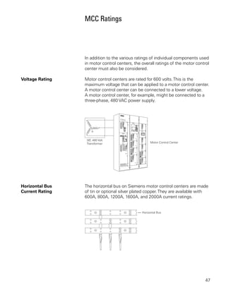
  • 1. MCC Ratings In addition to the various ratings of individual components used in motor control centers, the overall ratings of the motor control center must also be considered. Voltage Rating Motor control centers are rated for 600 volts. This is the maximum voltage that can be applied to a motor control center. A motor control center can be connected to a lower voltage. A motor control center, for example, might be connected to a three-phase, 480 VAC power supply. Horizontal Bus The horizontal bus on Siemens motor control centers are made Current Rating of tin or optional silver plated copper. They are available with 600A, 800A, 1200A, 1600A, and 2000A current ratings. 47
  • 2. Vertical Bus The vertical bus on the TIASTAR motor control centers are available with 300A and 600A ratings. Bus Bracing Motor control centers must be capable of withstanding the largest potential short-circuit current which can occur in the selected application. The amount of short-circuit current available depends on the amount of power available to a facility. Short-circuit current can be thousands of times higher than normal current. Bus bars must be braced to withstand this potential current. Siemens bus bars are braced for 42,000 AIC (ampere interrupting capacity) with optional bracing available to 100,000 AIC. 48
  • 3. Temperature Rise The bus bars are the major current carrying component of the motor control center. Before a motor control center is operated, bus bars are at the temperature of the surrounding air. This is known as ambient temperature. Temperature rises in the motor control center bus bars during operation. The combination of ambient temperature and allowed temperature rise equals the maximum temperature of the bus bars. NEMA and UL both have standards concerning the maximum temperature rise of bus bars used in motor control centers. NEMA limits temperature rise to 65°C based on an ambient temperature of 40°C (104°F), for a maximum operating temperature of 105°C. UL limits temperature rise to 50°C based on an ambient temperature of 40°C (104°F), for a maximum operating temperature of 90°C. Electrical equipment bearing a UL mark must meet or exceed this standard. Siemens motor control centers meet or exceed NEMA and UL standards. Bus bars in Siemens motor control centers are tested with a maximum temperature rise of 50°C over 40°C (104°F) ambient. 49
  • 4. Enclosures NEMA defines an enclosure as a surrounding case constructed to provide a degree of protection to personnel against incidental contact with the enclosed equipment and to provide a degree of protection to the enclosed equipment against specified environmental conditions (NEMA Standard 250 - section 2, definitions). The following brief descriptions cover enclosures available for Siemens motor control centers. Type 1 Enclosure Type 1 enclosures are intended for indoor use primarily to provide protection against limited amounts of falling dirt and contact with the enclosed equipment in locations where unusual service conditions do not exist. 50
  • 5. Type 1 Gasket Front Type 1 gasketed front, general purpose, indoor enclosure has the same use as Type 1 except the front of the enclosure is gasketed. In addition the following parts are gasketed: Unit separator angles Right-hand side of front of units Bottom horizontal cross ties Lip on top plate Pilot-device panel Handle mechanism Bottom horizontal wireway cover plate Side holes are plugged Type 2, Drip-Proof Type 2, drip-proof is an indoor enclosure intended to protect equipment from falling noncorrosive liquids and dirt. The enclosure prevents the entrance of dripping liquid at a higher level than the lowest live part within the enclosure. This design is a Type 1 gasketed front, or Type 12, with a drip shield mounted on top of the enclosure. Type 12 Enclosure Type 12 enclosures are intended for indoor use primarily to provide a degree of protection against circulating dust, falling dirt, and dripping noncorrosive liquids. They are not intended to provide protection against conditions such as internal condensation. The Type 12 will provide a greater degree of protection than a Type 1 gasketed enclosure. The following additional parts are gasketed: Hinged side of doors Top plates Wireway end-covers Rear plates There is no gap between sections, allowing for much greater dust resistance. In addition, interconnection holes in the side sheet assemblies are sealed. Bottom plates are included. 51
  • 6. Type 3R Enclosure Type 3R enclosures are intended for outdoor use primarily to provide a degree of protection against falling rain and sleet and protection from contact with the enclosed equipment. They are not dust, snow, or sleet (ice) proof. They will prevent entrance of rain at a level higher than the lowest live part. The enclosure has provisions for locking and drainage. The enclosure entirely surrounds the motor control center for outdoor operation. The Type 3R enclosure is designed to accommodate bottom cable entry and exit only. The 3R enclosure is not a walk-in type design. NEMA and IEC The International Electrotechnical Commission (IEC) is another organization that defines the degree of protection provided by enclosures. NEMA is primarily associated with equipment used in North America. IEC is associated with equipment sold in many countries including the United States. The IEC designation consists of the letters IP followed by two numbers. The first number indicates the degree of protection provided by the enclosure with respect to persons and solid objects entering the enclosure. The second number indicates the degree of protection against the ingress of water. The following chart provides an equivalent conversion between NEMA and IEC designations. NEMA IEC 1 IP10 2 IP11 3R IP14 12 IP52 52
  • 7. Classification and Types of Wiring NEMA has established two classification standards (Class I and Class II) and three types of wiring (A, B, and C) used in the construction of motor control centers. These are specified by the customer. Class I Class I consists of a grouping of combination motor control units in which each starter and motor operates independently of the other starters. The factory connects the combination motor control units to the vertical bus but does not provide interconnecting wiring between combination motor control units, different vertical units, or remotely connected devices. Diagrams of the individual units only are supplied. Class I, Type A Wiring Type A wiring is only available on Class I motor control centers. The motor control center manufacturer connects the combination motor control unit to the vertical bus via the stabs on the back of the unit. Power is applied to the circuit breaker from the vertical bus. The circuit breaker is factory wired to the motor starter. The customer connects the motor leads and control wiring to the motor starter. There is no interconnecting wiring between combination motor control units. 53
  • 8. Class I, Type B Wiring Typically pilot devices, such as indicator lights, pushbuttons, and selector switches, are used with Class I, Type B wiring. Type B wiring is divided into two designations: B-d (-d for connection of load wires directly on starter or contactor terminals) and B-t (-t for connection of load wires to unit mounted load terminal blocks). When Type B-d wiring is specified, terminal blocks are furnished near the wireway for control circuit connections. Motor leads are connected directly to the overload relay terminals. When Type B-t wiring is specified, terminal blocks are furnished near the wireway for control circuit connections and for motor starter leads. Type B-t wiring can be used on starters up to size 3. 54
  • 9. Class I, Type C Wiring With Type C wiring, a master terminal block is provided in either the top or bottom horizontal wiring gutter. The manufacturer of the motor control center brings the control wires from each control unit to the master terminal block. The installer is then able to make his wiring connections at the master terminal block. With Type C wiring, load wiring for combination motor control units smaller than size 3 (50 HP) are connected to the master terminal block. Load wiring for combination motor control units larger than size 3 are connected directly to unit device terminals.. 55
  • 10. Class II Class II consists of a grouping of combination motor control units with interwiring and interlocking between the starters to form a complete control system. Wiring diagrams, including the interwiring, is furnished. Class II is generally specified when a group of motors requires sequencing, interlocking, or interconnecting. Class II, Type B Class II, Type B wiring is similar to Class I, Type B wiring. Terminal blocks are furnished near the wireway. In addition, Class II, Type B wiring includes interconnecting wiring between motor starters. 56
  • 11. Class II, Type C Class II, Type C wiring is similar to Class I, Type C wiring. In addition, Class II, Type C wiring includes interconnecting wiring between motor starters and vertical sections. Reference Chart The following chart provides a handy reference when determining the class and type of wiring used in motor control centers. 57
  • 12. Cable Entry There are several ways incoming power can be terminated in a motor control center. Cable can be routed directly to the incoming power lugs, to main breakers or disconnects, or to a terminal block in a vertical section. In addition, incoming power cables can enter and exit the motor control center from the top or bottom depending on the application. Main Lugs When using main lugs the amount of vertical space required varies with the amperage rating. When the main lugs are located on the top, as in the following illustration, the vertical space is taken at the top. A motor control center can also have the lugs located at the bottom of the MCC. In the following illustration, for example, main lugs rated for 600 amps are located on the top of the MCC. In this example 24” of vertical space is required. 58
  • 13. Main Lugs on Top, In the arrangement illustrated below incoming power cables Top Entry enter through the top of a vertical section and are connected to main lugs. Main Lugs on Top, Incoming cables can also enter from the bottom and connect to Bottom Entry main lugs located in the top section. Main Lugs on Bottom, Lugs can also be supplied on the bottom of the vertical bus for Bottom Cable Entry bottom cable entry. 59
  • 14. Disconnect Device When a main disconnect device, such as a circuit breaker or fusible disconnect, is used, the disconnect is mounted in its own unit. The amount of space required depends on the disconnect used. The space can vary from 12” to 72” . In the following illustration a main circuit breaker is used. Cable entry can be from the top or bottom of the vertical section. 60
  • 15. Review 5 1. The maximum current rating for a horizontal bus on Siemens motor control center is ____________ amps. 2. The maximum bus bracing available for a Siemens motor control center is ____________ AIC. 3. The IEC equivalent of a NEMA Type 3R enclosure is ____________ . 4. Identify the following types of Class I wiring: 61
  • 16. TIASTAR TIASTAR™ is trade name of the motor control centers that Siemens manufactures. Several mechanisms and features have been designed into TIASTAR. Many of these features will be discussed in this section. 62
  • 17. Dimensions The nominal height of TIASTAR is 90” high. The overall height is 91 1/8” including a standard 1 1/8” base channel. There are 72” of vertical space available for combination motor control units, with 12” at the top and 6” at the bottom for wiring. The horizontal power bus is located in the 12” of top space making it easier to service. Each vertical unit will hold up to six 12” units (6 x 12 = 72). An optional pull box (top hat) can be supplied when extra wire-bending space is required. Pull boxes can be 12” 18” or 24” high. , , Vertical structures are 20” wide. A 30” wide unit is available for special units, such as large AC drives or transformers that require more space. The vertical wireway is 4” wide on 20” wide sections. An optional 8”-wide wireway is available on 20” wide sections. Vertical units can be 15” or 20” deep. 63
  • 18. Back-to-Back Mounting A feature of TIASTAR motor control centers is the ability to mount combination motor control units back to back. This permits mounting 12 combination motor control units in 72” of vertical space. TIASTAR vertical units designed for back-to-back mounting are 21” deep. Back-to-back combination motor control units use the same stab-on connection as front mounted units. 64
  • 19. Basic Construction TIASTAR motor control centers offer two vertical bus designs. Front only structures with 42K or 65K bus bracing are supplied with an insulated vertical bus design standard. The vertical bus bars are not physically isolated phase-to-phase. An optional isolated and insulated vertical bus assembly is available for front only 42K and 65K bus bracing. The isolated and insulated vertical bus design is standard for 100K bus bracing and all back-to-back structures. Combination motor control units can be interchanged and are easily rearranged on either bus assembly. The unit support brackets can be repositioned to accommodate various size units. 65
  • 20. Horizontal Bus The horizontal bus is connected to the vertical bus with a two-bolt, U-shaped clamp utilizing spring washers to maintain torque. This allows the bolts to be tightened from the front. Horizontal bus bars are shielded by a clear polycarbonate cover for safety and easy visibility for inspection. Ground Bus A horizontal ground bus is mounted in the bottom 6” of space. The horizontal ground bus is standard. An optional vertical ground bus can be connected to the horizontal bus. When a combination motor control unit is instered into the MCC the vertical ground bus is the first item engaged. Likewise, when the unit is removed the vertical ground bus is the last thing to be disengaged. 66
  • 21. Wire Tie Rods Round wire tie rods are located in each vertical wireway to hold wire harnesses in place. Pilot Devices Pilot devices are mounted on a panel which latches onto the unit door with a simple tab-and-notch mechanism. The pilot- device panel can be removed from the door and attached to the combination motor control unit for service or unit removal. There is room for four 30mm pilot devices on the panel. 67
  • 22. Terminal Blocks Terminal blocks are supplied with Type B and C wiring. The terminal blocks are mounted up front on a swing-out side panel. The panel is notched so that the terminal block can be placed inside the unit, in a center position, or in the vertical wireway. This secures the terminals inside the unit when access is not required, or allows access from the vertical wireway. Pull-apart terminals are available as an option. Operating Handle The disconnect operating handle has four positions. When placed in the “PARK” position the unit door can be opened without the handle interfering. The “TRIPPED” position is clearly indicated. 68
  • 23. Racking Lever A racking lever located on each combination motor control unit is used to remove or install the unit. When the operator handle is in the “ON” position, a locking pin blocks the racking lever closed. When the operator handle is switched to the “OFF” position, the locking pin disengages the racking lever. The combination motor control unit can be pulled to a test position. The operator handle is placed in “PARK” to completely remove the combination motor control unit. The unit is designed so that it cannot be inserted or removed with the operator handle in the “ON” position. In the test position the unit can be padlocked in place. Ground Clip A copper clip on the side of the combination motor control unit engages the unit support bracket, grounding the unit to the motor control center at all times. An optional vertical bus stab is mounted on the unit when a vertical ground bus is used. 69
  • 24. Locking The disconnect operating handle can be locked in the “OFF” position with up to three padlocks. High Density Units TIASTAR is also available with high density units. High density units are 6” tall. A maximum of 12 high density units can be installed in 72” of vertical space. High density combination motor control units are available in NEMA size 0 (5 HP) and size 1 (10 HP). To compliment the high density unit, a 24” wide structure is available with an oversized (8” wide) vertical wireway. While the 24” wide structure allows for the increased quantity of wires typical of high density applications, they are not required when high density units are used. 70
  • 25. Combination Units High density units have many of the same features as the full size units. The disconnect operating handle is mounted sideways. When Type B or C wiring is specified, a swing-out terminal block is supplied. The motor starter is located behind the terminal block. The circuit breaker is located behind the operator handle. A unique “swing out” feature permits components to swing out of the unit for easy inspection or maintenance. 71
  • 26. Information Needed to Order MCCs When ordering a motor control center several questions need to be answered. The following information will be useful. • Voltage, frequency, number of phases, and available fault current of power supply • Incoming power requirements (main circuit breaker, main fusible switch, main lugs only, or splicing to existing MCC) • Amp rating of the horizontal bus and finish material (tin or silver) • Voltage rating and source of control power • Size, type (aluminum or copper), number per phase and location of incoming cables or busway and outgoing cables • Enclosure - Type, finish - Accessibility (front, rear, or both) - Clearance for door swing - Restrictions on height, width, and depth • Horsepower rating and motor design of motors to be controlled • Ampacity of feeder tap units and unit disconnect devices • Type of disconnect for units: thermal-magnetic, instantaneous trip, or fusible • Ground bus requirements • Types of starting method of combination motor-control units, such as FVNR, FVR, 2S1W, 2S2W, PW, or RVAT • Type of control circuit for units 72
  • 27. Service entrance requirements • Vertical bus requirements (finish, isolated/insulated, amp rating) • Class and Type of wiring • Additional equipment requirements (transformers, panelboards, transfer switches, PLCs, etc.) • Preferred layout of units • Special features, codes, or restrictions • Customer specifications • Drawing requirements 73
  • 28. Review 6 1. The maximum height of an optional pull box for the TIASTAR is ____________ inches. 2. A maximum of ____________ high density units can be mounted in 72” of vertical space. 3. High Density units are available in NEMA size ____________ and NEMA size ____________ . 4. The horizontal power bus is located in the 12” of ____________ space. 5. Isolated and insulated vertical bus design is standard for ____________K bus bracing and all back-to-back structures. 6. Vertical space for the TIASTAR motor control center is ____________ inches. 7. The horizontal ground bus for TIASTAR motor control centers is typically located in the ____________ 6” of space. 8. TIASTAR back-to-back structures are ____________ inches deep. 74
  • 29. Review Answers Review 1 1) d; 2) TIASTAR; 3) 3; 4) 2. Review 2 1) Underwriters Laboratories; 2) National Fire Protection Association; 3) 200,000; 4) 430-94. Review 3 1) B; 2) 80; 3) B; 4) A; 5 ) B. Review 4 1) 10; 2) 3; 3) 200; 4) f; 5) SIRIUS and SIKOSTART. Review 5 1) 2000; 2) 100,000; 3) IP14; 4) a=A, b=B-t, c=B-d, d=C Review 6 1) 24; 2) 12; 3) 0 and 1; 4) top; 5) 100; 6) 72; 7) bottom; 8) 21. 75
  • 30. Final Exam The final exam is intended to be a learning tool. The book may be used during the exam. A tear-out answer sheet is provided. After completing the test, mail the answer sheet in for grading. A grade of 70% or better is passing. Upon successful completion of the test a certificate will be issued. Questions 1. ____________ is the trade name for a Siemens motor control center. a. SIKOSTART b. INNOVA PLUS c. SAMMS d. TIASTAR 2. Article ____________ of the National Electrical Code® requires overcurrent protection for MCCs. a. 430.94 b. 240 c. ICS-1-322 d. 430.97 3. Which of the following is not a part of the NEMA definition for motor control centers? a. Principally contains branch circuit protection b. Floor-mounted assemblies c. Common horizontal bus d. One or more vertical sections 4. The standard height of a vertical section is ____________ inches. a. 72 b. 40 c. 90 d. 20 76
  • 31. 5. The maximum shipping width of a motor control center assembly is ____________ inches. a. 60” b. 80” c. 90” d. 120” 6. According to NEC® Article 430.97 there should be , a minimum distance of ____________ inch(es) of clearance between a live bus and ground. a. 1 b. 2 c. 3 d. 4 7. A Class 20 overload relay will trip within ____________ seconds when motor current is 600%. a. 3 b. 10 c. 20 d. 30 8. ____________ is a motor protection device that is designed to work with PROFIBUS-DP . a. INNOVA PLUS b. SENSITRIP III c. FVNR d. SIMOCODE-DP 9. A NEMA size 3 controller is rated for __________ HP at 480 volts. a. 3 b. 25 c. 50 d. 100 10. Motor control centers are rated for ____________ volts. a. 480 b. 600 c. 1000 d. 1200 77
  • 32. 11. Up to ____________ 30 mm pilot devices can be mounted on the combination motor control unit door of a Siemens TIASTAR motor control center. a. 2 b. 4 c. 6 d. 8 12. Siemens motor control centers are manufactured with a maximum temperature rise of ____________ over 40°C ambient. a. 25°C b. 50°C c. 65°C d. 75°C 13. Type B-t wiring can be used on starters up to size ____________ . a. 3 b. 5 c. 6 d. 7 14. No terminal blocks are supplied on Class I, Type ____________ wiring. a. A b. B-t c. B-d d. C 15. Type ____________ wiring is not available on Class II motor control centers. a. all types are available on Class II b. A c. B d. C 16. The primary standards for MCCs are established by ____________ . a. ANSI, IEEE, IEC b. ANSI, NEC, IEC c. UL, IEEE, NEMA d. UL, NEMA, NEC® 78
  • 33. 17. TIASTAR high density units take up ____________ inches of vertical space. a. 18 b. 12 c. 6 d. 4 18. Most Siemens plug-in combination motor control units use ____________ for quick bus connect and disconnect. a. pull-apart terminal blocks b. two-bolt, U-shaped clamp c. shelf-brackets d. stab clips 19. To remove a combination motor control unit from a System/89 MCC, the operating handle is placed in ____________ . a. On b. Off c. Park d. Tripped 20. ____________ will allow the use of branch circuit protective units in a motor control center provided their use does not make up a major portion of the motor control center. a. NEMA (ICS-2-322) b. NEC® (430.97) c. NEC® (430.94) d. UL (845) 79
  • 34. quickSTEP Online Courses quickSTEP online courses are available at http://www.sea.siemens.com/step. The quickSTEP training site is divided into three sections: Courses, Downloads, and a Glossary. Online courses include reviews, a final exam, the ability to print a certificate of completion, and the opportunity to register in the Sales & Distributor training database to maintain a record of your accomplishments. From this site the complete text of all STEP 2000 courses can be downloaded in PDF format. These files contain the most recent changes and updates to the STEP 2000 courses. A unique feature of the quickSTEP site is our pictorial glossary. The pictorial glossary can be accessed from anywhere within a quickSTEP course. This enables the student to look up an unfamiliar word without leaving the current work area. 80