Block diagram reduction techniques in control systems.ppt
The Chimera Grid Concept and Application
1. Name: Putika Ashfar Khoiri (28J16118)
Email: putika@civil.osaka-u.ac.jp
Computational of Fluid Dynamics
Assignment 2
The Chimera Grid Concept and Application
The chimera grid scheme and similar scheme are using overset grids to resolve complex geometry of
flow features, are generally classified into complex structure grid category. Overset grids allow
structure grids to be used in good quality, such as orthogonally, smoothness and with ease to control
grid spacing in viscous layer. Furthermore, overset grids can be employed as a solution adaptation
procedure. However, the non-conservative interpolations to update variables in the overlapped
region, without strict satisfaction of the governing equation, can give rise to spurious solutions,
especially through regions of sharp gradients.
The chimera method is an outgrowth of the attempt to generalize a powerful solution approach (the
structured and body-conforming grid method) to complex situation. It has two principal elements; (1)
Decomposition of a chosen computation domain into sub-domains, and (2) communication of
solutions data among these sub-domains through an interpolation procedure.
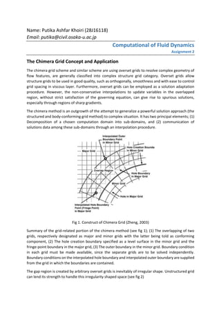
Fig 1. Construct of Chimera Grid (Zheng, 2003)
Summary of the grid-related portion of the chimera method (see fig 1); (1) The overlapping of two
grids, respectively designated as major and minor grids with the latter being told as conforming
component, (2) The hole creation boundary specified as a level surface in the minor grid and the
fringe-point boundary in the major grid, (3) The outer boundary in the minor grid. Boundary condition
in each grid must be made available, since the separate grids are to be solved independently.
Boundary conditions on the interpolated hole boundary and interpolated outer boundary are supplied
from the grid in which the boundaries are contained.
The gap region is created by arbitrary overset grids is inevitably of irregular shape. Unstructured grid
can lend its strength to handle this irregularity shaped space (see fig 2)
2. Fig 2. Arbitrary grid overlapping by non-structured grid in Chimera grid (Zheng, 2003)
The chimera grid method makes use of body fitted grids in which are an essential asset known to give
viscous solutions accurately and economically. In the gridding process the complex geometrical model
is divided up into sub-domains, which in general are associated with components of a configuration.
Each sub-domain is gridded independently and required to have overlapped region between the sub-
domains. The computational volumetric domain has been decomposed into many sub-domains filled
with structured grids. The sub-domains overlapped with each other. Hole boundaries and outer
boundaries are the two ways through which information is communicated from grid to another.
For example, the chimera grid method is used for integrated space shuttle geometry (complex
geometry) (see fig. 3)
Fig 3. NASA shuttle space appearance model construct in chimera grid (overset grid)
3. A surface element consists of several edges. An edge is referred to as an isolated edge, if it is belonging
to only one element of the surface. For general surface there are many edges which belong to two
neighbouring elements and clearly these edges are not isolated edges. Furthermore, for a closed
surface, there are no isolated edges. The corresponding isolated edges are bound the openings of the
surface. Therefore, in order to close the surface, it is natural to establish the isolated edge first, then
to identify facets which fill the openings.
Additional reference (is attached to email)
(1) Y. Zheng, M.-S Liou. A novel approach of three-dimensional hybrid grid methodology: Part 1.
Grid Generation. Computer Methods in Applied Mechanics and Engineering.192
(2003).4147-4171
4. ITTC (International Towing Tank Conference) – Practical Guides for Ship CFD
Application (2014)
The guidelines summarize the CFD process into three steps.
1. Pre-processing -> The definition of the geometry, computational domain and grids
2. Computation -> Analyse the data
3. Post-processing -> Visualisation, analysis, verification and the validation of the results.
The process must have to begin with calculate
1. The Reynold Number (Re)
In model scale, the Re is 106
and 109
in the full scale.
𝑅𝑒 =
𝜌𝑉𝐿
𝜇
Where, V = ship speeds, L = length between perpendicular, ρ = density, and µ =
viscosity.
2. Froude Number (Fr)
Its typically 0.1 for free surface flow simulations, and rarely above 1
𝐹𝑟 =
𝑉
𝑔𝐿
3. Mach Number (Ma)
It recommends to have the value of Ma ≤ 0.3. a = speed of sounds.
𝑀𝑎 =
𝑉
𝑎
1. Pre-processing
1.1 Geometry
Indicative tolerance for the geometry is ± 10-5
L, with L = ship length for the hull for Re
around 106
. This tolerance may need to be reduced when smaller scale appendages,
such as rudder or propeller are to be included in the flow computations or when it
requires smaller grid cells than the indicate CAD tolerance.
1.2 Computational domain and boundary conditions
- The computational domain should include inflow and outflow surfaces. A Dirichlet
condition (i.e. a known velocity field) should be imposed on the inflow boundary.
- Outflow face use different boundary condition. The option is use Neumann
condition (zero gradient) for velocity and pressure grid.
1.3 Grid
1.3.1 Structured grid
It shows regular connectivity in 2D quadrilateral and hexahedra in 3D. Mapping
the relation between the grid in the physical space (x, y, z) and the
computational space (i, j, k)
1.3.2 Unstructured grid
It shows irregular connectivity and the cells have several possible shapes
(tetrahedral, hexahedra, and other polyhedral). It doesn’t show a defined
topology and can be generated much more easily.
1.3.3 Hybrid grid and other techniques
It can use both structured and unstructured grids in different parts of the
domain. Other methods for this interpolation scheme may be defined by
interface where the interpolation method is defined across grid boundary
5. surfaces. For other methods, the interpolation scheme is defined by overlaps,
where the interpolation is defined across local grid volume.
1.3.4 Cell types
Quadrilateral (2D, 4 sided) and hexahedral (3D, 6 sided) cells are support by
almost all CFD codes. The usage is depending on:
o What cell types and the solver support
o The objective of the computations
o The hardware resources (are computational resources are available to run
case involving large grids?).
For complex geometries which high quality structured grid is difficult to
generate, it preferable using a hybrid unstructured grid or overlapping grids.
1.3.5 Grid resolutions
It should be decided based on the chosen turbulence model and on the
temporal or spatial scale of the flow features of interest. Always use orthogonal
grids to solve free surface flow simulations if it is possible.
1.3.6 Near-wall region
We have to define:
Friction velocity (u*
)
𝑢∗
= √
𝜏 𝑤
𝜌
Non-dimensional wall velocity (u+
)
𝑢+
=
𝑢
𝑢∗
Non-dimensional wall distance (y+
)
𝑦+
=
𝜌𝑢∗
𝜇
𝑦
Where 𝜏 𝑤= skin friction on the wall, u = local stream velocity component, y= wall
normal coordinate, Cf= friction coefficient
𝑦 =
𝑦+
𝐿
𝑅𝑒 𝐿
√
𝐶𝑓
2
Recommendation value for grid design at the wall
First point
Expansion
ratio
Points within
boundary layer
Near wall y+
≤ 1 1.2 20
Wall function 30 < y+
< 100 1.2 15
The volume of Cf for different conditions as follows:
Laminar
flow
Transitional flow
turbulence flow in
smooth surface
turbulence flow in rough
surface
𝐶𝑓 =
1.328
√ 𝑅𝑒 𝐿
𝐶𝑓 =
0.455
[ln(𝑅𝑒 𝐿)]2.58
−
1700
𝑅𝑒 𝐿
𝐶𝑓 =
0.455
[ln(𝑅𝑒 𝐿)]2.58
𝐶𝑓
=
1
[1.89 − 1.62ln(
𝜀
𝐿)]
2.5
6. 1.3.7 Grid Quality
Typically, the 3x3 determinant for structured grids should be greater than 0.3.
However, it may be necessary to have a few small cells where 3x3 determinant
is no better than 0.15.
2. Computation
2.1 Turbulence model
- RANS -> This approach assume that the turbulence is modelled with RANS where the
instaneous velocity is split into the sum of its statically average and turbulence
fluctuation which is modelled by the turbulence model.
- DNS -> Direct numerical simulation (DNS) solve the Navier-Stokes equations to the
resolution of the smallest turbulent scales but needs grids and time resolution which
are not yet achieve for high Re.
- LES -> Large Eddy Simulation (LES) is currently used for high demanding flow where
the transient nature of the turbulence needs to be resolved to smaller scales.
- DES -> Detached Eddy Simulation (DES) is a hybrid method that reduces the required
computational effort by solving the (unsteady) RANS equation in the near-wall
region and applying LES in the result of the domain.
2.2 Near-wall modelling
It requires grid nodes highly refined towards walls (y+
=1) in range 30 < y+
< 100. Two
approach are available:
1. Use of near wall turbulence models.
2. Use of wall function to bridge the solutions in the fully turbulent.
2.3 Surface roughness
1. If the physical roughness height (ks) is less than the thickness of the laminar sub-
layer, then the flow in the boundary layer is not affected.
2. If 𝑘 𝑠 =
2𝑣
𝑢∗, the effect of surface roughness is negligible.
2.4 Numerical schemes
1. First-order upwind (FOU) schemes
It introduces large numerical diffusion and very stable
2. Second-order upwind (SOU) schemes
It uses flux limiter to suppress unphysical oscillations in the solutions. It also
recommends for all convection-diffusion transport equations.
2.5 Time step
Courant-Friedrichs-Lewy (CFL) is the condition to resolve the flow features interest,
where Cmax ≥ 1
|𝑢|∆𝑡
∆𝑥
< 𝐶 𝑚𝑎𝑥,
for ∆𝑡 ≤ 0.01
𝐿
𝑈
(turbulence model) and ∆𝑡 ≤ 0.001
𝐿
𝑈
( Re stress turbulence model)
2.6 Convergence
Convergence must be evaluated at each time-step. The residual (L) for a discretised
equation is defined as (L1-Norm). (L2-Norm) is used to define the residual
7. 3. Post processing
3.1 Visualisation
A number of post processing plots should be used as a minimum sub-set of information
to ensure that the correct settings have been used for each computations
3.2 Verification and validation
Refers to the ITTC procedure 7.6 – 03 – 01 – 01 for “methodology and procedures for
estimating the uncertainty in a simulation result”.