Vickers check valves come in inline, right angle, and manifold mounted designs. Right angle check valves are designed for higher flows with less pressure drop than inline models. They have hardened and ground steel seats and poppets for improved cycle life. Pilot operated check valves allow reverse flow when a pilot pressure signal is applied, while maintaining very low internal leakage. They are typically used to lock cylinders in place.
1. Check Valves
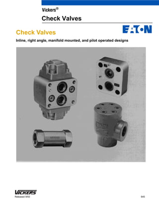
Inline, right angle, manifold mounted, and pilot operated designs
645Released 9/93
Vickers®
Check Valves
2. 2
Introduction
Vickers inline, right-angle, and manifold
mounted check valves are direct
operated and used in hydraulic circuits
to allow the free flow of fluid in one
direction only. The graphical symbol for
these valves is a spring-loaded ball and
a seat, as shown below.
Direct operated
Free flow No flow
A light spring holds the valve poppet in
its normally closed position. The valve
starts to pass fluid at a pressure
equivalent to the spring cracking
pressure level. Various spring
(cracking) pressures are available to
suit aplication requirements.
All except inline models can be used for
high velocity flows resulting in shock
conditions. Inline models are designed
for low shock service.Inline check valves
can be used as
a safety bypass for flow surges
through filters and heat exchangers.
With a higher spring rating, they can
also be used as a means of generating
pilot pressure.
Right angle check valves are designed
for higher flows with less pressure drop.
The valves’ seat and poppet are of
hardened and ground steel for
improved cycle life. An orifice plug can
be placed in the poppet to permit a
restricted flow through the valve in its
normally closed position; as such, these
valves are typically used in controlling
the rate of decompression in a large
press before shifting the main valve.
Pilot operated valves, like direct
operated valves, permit free flow in one
direction and prevent flow in the reverse
direction. However, pilot operated valves
permit reverse flow when a pilot
pressure signal is applied to the valve’s
pilot port. The graphical symbol for
these valves is shown below. Pilot
operated valves have very low internal
leakage and are typically used to lock a
cylinder in place until the main
directional valve shifts.
Pilot Operated
In Out
"
Pilot
Note: Vickers also has a range of SAE
flange mounted check valves, and ISO
4401-03 and -05 stackable check
valves. Flange mounted models are
described in publication 627. Size -03
and -05 stackable models are described
in publications GB-C-2027 and
GB-C-2022, respectively.
4. 4
Inline Check Valves
12 (3.2)
30 (8.0)
75 (20)
200 (50)
Nominal Size (in inches)
02 – 1/4 (not available in DS8P1 series)
03 – 3/8
06 – 3/4
10 – 1-1/4
Cracking Pressure
5 – 0,35 bar (5 psi)
30 – 2,0 bar (30 psi)
65 – 4,5 bar (65 psi)
Model Series
DS8P1 – SAE straight treaded ports
DT8P1 – NPTF pipe threaded ports
3 41 2
Model Code
1
D*8P1 - ** - ** - 1*
Ratings and Specifications
Design Number
10 – For “02” and ”03” size
11 – For “06” and “10” size
Subject to change. Installation
dimensions remain unchanged for
designs 10 through 19.
4
3
2
Model Series Maximum Operating
Presure – bar (psi)
Flow Capacity
l/min (USgpm){
Approximate
Weight – kg (lb)
DT8P1-02
D*8P1-03
D*8P1-06
D*8P1-10
0,10 (.50)
0,34 (.75)
0,68 (1.5)
2,70 (6.0)
210 (3000)
210 (3000)
210 (3000)
210 (3000)
Pressure Drop
{ Using hydraulic oil with viscosity rating of 32 cSt (150 SUS) at 38_C (100_F).
Pressure Drop Across
D*8P1-**-5-1* Models
USgpm
l/min
D*8P1-03
D*8P1-06
D*8P1-10
10
90 135 180
20
45
30 40 50
Flow rate
Pressuredrop–psi
Pressuredrop–bar
0,7
1,4
2,1
10
20
30
5. 5
–
.7500-16 UNF-2B
1.0625-12 UNF-2B
1.0625-12 UNF-2B
1.6250-12 UNF-2B
To hydraulic
system
Installation Dimensions
Millimeters (Inches)
Typical Applications
CAUTION:
Do not use this valve to check a high
velocity reverse flow resulting in shock
conditions. (See typical applications
below.) Where such conditions exist,
Vickers C2-8** or C5G-8** type check
valve should be used.
22,4 (0.88)
25,4 (1.00)
38,1 (1.50)
38,1 (1.50)
63,5 (2.50)
Model Series A B
“T” NPTF
Pipe Thd.
DT8P1-02
D*8P1-03
DT8P1-06
DS8P1-06
D*8P1-10
1/4
3/8
3/4
3/4
1-1/4
57,2 (2.25)
76,2 (3.00)
98,6 (3.88)
104,0 (4.09)
134,4 (5.25)
“S” Straight Thread
D*8P1 Inline Check Valve Can Be Used
C2-8** or C5G-8** Type Check Valve Should Be Used
A B
Inlet connection.
“S” straight threads or
“T” NPTF pipe threads
Outlet connection.
“S” straight threads or
“T” NPTF pipe threads
Heat exchanger
Tank
Delivery-
from pump
To hydraulic system
Directional valve
D*8P1 inline check valve, free flow
High inertia
reversing load
Reciprocating motion with over-running
loads, either direction
Delivery-
from pump
Tank
D*8P1 inline check valve,
free flow
To hydraulic
system
To hydraulic
system
Directional
valve
Pump
Free
flow
C2-8** right-angle
check valve
Accumulator
Delivery-
from pump
C2-8**
right angle
check valve
Unloading relief valve
Discharge to tank
Pressure adjustment
Free flow
Free Flow
6. 6
Right Angle Check Valves
Right Angle Type Valve
Port Size
00 – 1/4” NPT
05 – 3/8” NPT or
.7500-16 UNF-2B (.500 tubing)
15 – 3/4” NPT or
1.0625-12 UNF-2B (.750 tubing)
20 – 1” NPT
25 – 1-1/4” NPT or 1.6250-12 UNF-2B
(1.250 tubing)
30 – 1-1/2” NPT
35 – 2” NPT
Check Valve
Design Number
Subject to change.
Port Threads
Blank – NPT threads
S – Straight threads
1,4 (3)
1,4 (3)
2,3 (5)
3,6 (8)
4,8 (10.5)
4,8 (10.5)
12,2 (27)
Cracking Pressure
Blank – 0,3 bar (5 psi), standard
S2 – 2,4 bar (35 psi)
S3 – 3,4 bar (50 psi)
S8 – 5,2 bar (75 psi)
S12 – 0,3 bar (5 psi) and plug in
poppet. (See view below.)
S17 – 8.6 bar (125 psi)
S19 – 1,4 bar (20 psi)
2
11 (3)
25 (6)
60 (16)
100 (28)
170 (45)
250 (65)
400 (100)
3 41 2
Model Code
1
C 2 (S) - 8 ** - (***)
Ratings and Specifications
3
Model Series
Maximum
Operating
Pressure
bar (psi)
Nominal
Flow Capacity
l/min (USgpm)
Approx.
Weight
kg (lb)
C2-800
C2(S)-805
C2(S)-815
C2-820
C2(S)-825
C2-830
C2-835
210 (3000)
210 (3000)
210 (3000)
210 (3000)
210 (3000)
210 (3000)
210 (3000)
5 6
4
5
6
Construction of
“S12” Cracking
Pressures Model
Approximate
Pressure Drop
at Rated Flow
bar (psi) {
{ Using SAE 10W Oil at 49_C (120_F)
1,2 (18)
1,4 (20)
1,4 (20)
1,0 (14)
1,0 (14)
1,6 (23)
1,4 (20)
Solid plug
(Can be drilled
to suit orifice
requirement)
7. 7
31,8 (1.25)
31,8 (1.25)
46,0 (1.81)
57,1 (2.25)
66,5 (2.62)
66,5 (2.62)
91,9 (3.62)2” NPT
1/4” NPT
3/4” NPT
58,7 (2.31)
58,7 (2.31)
81,0 (3,19)
98,6 (3.88)
107,9 (4.25)
107,9 (4.25)
149,3 (5.88)
1-1/2” NPT
31,8 (1.25)
31,8 (1.25)
50,8 (2.00)
57,1 (2.25)
76,2 (3.00)
76,2 (3.00)
88,9 (3.50)
53,8 (2.12)
53,8 (2.12)
69,8 (2.75)
82,6 (3.25)
82,6 (3.25)
82,6 (3.25)
114,3 (4.50)
74,7 (2.94)
74,7(2.94)
98,6 (3.88)
115,8 (4.56)
138,2 (5.44)
138,2 (5.44)
187,4 (7.38)
26,1 (1.03)
26,1 (1.03)
44,4 (1.75)
46,7 (1.84)
66,5 (2.62)
66,5 (2.62)
73,1 (2.88)
1.6250-12 UNF-2B
C2-800
C2(S)-805
C2(S)-815
C2-820
C2(S)-825
C2-830
C2-835
1.0625-12 UNF-2B
Installation Dimensions
Millimeters (Inches)
Model
Series “S” Straight Thread
{ Using SAE 10W Oil at 49_C (120_F)
“P” Pipe
Thread A B C D E F
–
–
–
–
1” NPT
.7500-16 UNF-2B 3/8” NPT
1-1/4” NPT
A
B
C
D
C
E
F
Outlet port.
“S” straight thread or
“P” NPTF pipe thread
Inlet port.
“S” straight thread or
“P” NPTF pipe thread
8. 8
Manifold Mounted Check Valves
86
(400)
Nominal Size
805 – 3/8” pipe or 1/2” tube
815 – 3/4” pipe or 3/4” tube
825 – 1-1/4” pipe or 1-1/4” tube
Design Number
Subject to change.
Subplate or Manifold Mounted
nP
bar (psi)
18,9 (5)
37,8 (10)
56,8 (15)
75,7 (20)
37,8 (10)
75,7 (20)
113,6 (30)
151,4 (40)
94,6 (25)
189,3 (50)
283,9 (75)
378,5 (100)
473,2 (125)
Check Valve
4
5
Cracking Pressure
Blank – 0,3 bar (5 psi), standard
S3 – 3,4 bar (50 psi)
S8 – 5,2 bar (75 psi)
1,2 (2.7)
2,9 (6.5)
6,1 (13.5)
2
40 (10)
75 (20)
400 (100)
3 41 2
Model Code
1
(F3) - C 5 G - 8 ** - (**)
Ratings and Specifications
3
Model
Series
Maximum
Operating
Pressure
bar (psi)
Nominal
Flow Capacity
l/min (USgpm)
Approximate
Weight
kg (lb)
C5G-805
210 (3000)
210 (3000)
210 (3000)
5 6
6
Pressure Drop
Flow Rate
l/min (USgpm)
0,9 (13)
1,2 (17)
1,5 (22)
1,9 (27)
0,5 (7)
1,0 (15)
1.7 (25)
2,4 (35)
0,6 (8)
0,8 (12)
1,1 (16)
1,5 (22)
2,1 (30)
C5G-815
C5G-805
C5G-815
C5G-825
Model Series
Pressure Drop for Free Flow Across
Check Valve
C5G-825
1. Figures in the chart at left give approximate pressure drops (n P) when pasing
21 cSt (100 SUS) fluid having .865 specific gravity.
2. For any other viscosity, pressure drop (nP1) will be:
Viscosities – cSt (SUS)
% of nP (Approximate)
14
(75)
32
(150)
43
(200)
54
(250)
65
(300)
76
(350)
93 111 119 126 132 137 141
3. For any other specific gravity (G1), pressure drop (nP1) will be approximately:
nP1 = nP (G1/G). (Obtain specific gravity figure from fluid producer; figure will
be higher for fire-resistant fluids than for oil.)
Special Seals
See “Seals” section on page 15.
Omit for standard seals.
9. 9
30,2
(1.19)
Outlet
conn.
6,3
(.25)
7,92
(.312)
hex.
O 10,72 (.422) thru
O 17,5 (.69) spotface
4 holes for mounting
23,9 (.94)
Mounting Pad
A machined pad, as indicated by
shaded area, must be provided for
mounting. Pad must be flat within
0,013 mm (.0005 in.) and smooth
within 1,6 micron (63 microinch).
Mounting Bolt Kits
Mounting bolts must be ordered separately.
Example:
One (1) C5G-805 Check Valve
One (1) BKCG-805-619 Bolt Kit
Bolt thread size is .375-16, and bolt length
is 1.75 (both in inches). Maximum bolt
torque is 35 Nm (26 lbf. ft.).
Mounting bolts, when provided by customer,
must be SAE grade 7, or better.
65 (2.56)
47,7 (1.88)
60,4
(2.38)
O 7,14 (.281). 7,9 (.31) deep.
2 holes (For locating pins)
77,7
(3.06)
47,8 (1.88)
65 (2.56)
Outlet connectionO 14,68 (.578) 2 places
12,7 (.50)
47,8
(1.88)
.375-16 UNF-2B thread.
4 holes (Valve mtg.)R 8,6 (.34)
Outlet port
Mounting surface
Inlet port
Direction of oil flow
R 8,6 (.34)
60,4
(2.38)
12,7 (.50)
77,7
(3.06)
O 6,3 (.25)
2 locating pins. See
mounting pad for
location dimensions.
3 (.12)
33,3
(1.31)
65,8
(2.59)
O 22,3 (.88)
O 33,3 (1.31)
Installation Dimensions – C5G-805 Series
Millimeters (Inches)
10. 10
Mounting Bolt Kits
Mounting bolts must be ordered separately.
Maximum bolt torques are 47 Nm (35 lbf. ft.)
and 95 Nm (70 lbf ft.) for .625-11 and
.750-10 bolts, respectively.
Mounting bolts, when provided by customer,
must be SAE grade 7, or better.
.625-11 1.75 inch
.750-10 3.50 inch
Bolt Thd. Length
C5G-815
C5G-825
BKCG815-612
BKCG10-616
Installation Dimensions – C5G-815 and C5G-825 Series
Millimeters (Inches)
N
R
Bolt KitValve Series
D
C
Mounting surface
(Seals furnished)
Direction of
oil flow
Outlet connection
Inlet connection
B
L
G
6,4
(.25)
O 6,4 (.25) 2 places
E Hex.
F
P
A
O H thru. J counterbore - K deep.
4 holes for mounting (NOTE: J is
spotface for C5G-825)
Radius V
Mounting Pad
A machined pad, as indicated by
shaded area, must be provided for
mounting. Pad must be flat within 0,013
mm (.0005 in.) and smooth within 1,6
micron (63 microinch).
O 7,14 (.281). 7,8 (.31) deep.
2 holes (For rest pins)
U
N
T thread. 4 holes
for mounting valve.
P
Radius V
A
B
M
L
R
Q
O S
O W
Model
Series A B C D E F G H J K
C5G-815 96,8
(3.81)
112,8
(4.44)
76,2
(3.00)
11,2
(.44)
41,1
(1.62)
50,8
(2.00)
38,1
(1.50)
16,66
(.656)
25,4
(1.000)
15,7
(.62)
C5G-825 127
(5.00)
127
(5.00)
110,2
(4.34)
10,4
(.41)
47,7
(1.88)
66,5
(2.62)
57,9
(2.28)
19,84
(.781)
30
(1.18)
–
Model
Series L M N P Q R S T U V W
C5G-815 81
(3.19)
40,4
(1.59)
65
(2.56)
32,5
(1.28)
68,3
(2.69)
22,3
(.88)
23,01
(.906)
.625-11
UNC-2B
8,6
(.34)
15,7
(.62)
23.01
(.906)
C5G-825 91,9
(3.62)
46
(1.81)
91,9
(3.62)
46
(1.81)
71,4
(2.81)
20,6
(.81)
34,92
(1.375)
.750--10
UNC-2B
9,6
(.38)
17,5
(.69)
28,6
(1.125)
11. 11
Pilot Operated Check Valves
“C” in
Formula
Below
210 (3000)
210 (3000)
210 (3000)
210 (3000)
210 (3000)
210 (3000)
210 (3000)
210 (3000)
210 (3000)
50 (12)
50 (12)
50 (12)
100 (30)
100 (30)
100 (30)
300 (75)
300 (75)
300 (75)
“P” Out – “P” In
Area Ratio
Pressure Drop
bar (psi) {
Special Seals
See “Seals” section on page 15.
Omit for standard seals.
2
14
21
58
09
22
43
12
29
58
1,7 (25)
1,7 (25)
1,7 (25)
2,7 (40)
2,7 (40)
2,7 (40)
3,4 (50)
3,4 (50)
3,4 (50)
3.11:1
3.11:1
3.11:1
3.12:1
3.12:1
3.12:1
2.6:1
2.6:1
2.6:1
30:1
30:1
30:1
48.2:1
48.2:1
48.2:1
77:1
77:1
77:1
The ratio between a check valve’s pilot
pressue area and poppet area must be
greater than the ratio between a
hydraulic cylinder’s piston and annulus
areas. If it is not, the valve will not open
to permit reverse flow. For example, if
the cylinder has a piston-to-annulus
area ratio of 2:1, the valve must have a
greater (3:1) ratio.
Nominal Valve Size
03 – 3/8” pipe or 1/2” tubing
06 – 3/4” pipe or 3/4” tubing
10 – 1-1/4” pipe or 1-1/4” tubing
Check Valve
Mounting Type
G – Manifold or subplate
S – SAE straight thread
T – NPTF thread
4
Design Number
20 – For 4CG models
21 – For 4CS and 4CT models
Subject to change. Installation
dimensions remain unchanged for
designs 20 through 29.
Decompression Poppet
D – With decompression.
Omit if not required.
(See “Pilot Area and Cylinder Ratios”
section below.)
Cracking Pressure
A – 2 bar (30 psi)
C – 5 bar (75 psi)
F – 10 bar (150 psi)
3 41 2
Model Code
1
(F3) - 4C * - ** - (D) * - 2*
Ratings and Specifications
3
Model
Series
Maximum
Operating
Pressure
bar (psi)
Nominal
Flow Rating
l/min (USgpm)
4C*-03-A
4C*-03-C
4C*-03-F
4C*-06-A
4C*-06-C
4C*-06-F
4C*-10-A
4C*-10-C
4C*-10-F
5 6 7
5
6
7
D D D
{ Approximate pressure drop at rated flow. D Valve held open by pilot pressure. DD Free flow across poppet.
3,8 (55)
6,2 (90)
13,1 (190)
4,5 (65)
9,0 (130)
15,8 (230)
3,4 (50)
8,3 (120)
13,8 (200)
Pilot Area and
Cylinder Ratios
With large check valves or large
differential-area cylinders, the valve’s
ratio may be difficult to acieve. For
these cases, a decompression-type
check valve, which can have an
opening ratio of 30:1 or greater, can
be used .
A decompression poppet (within the
main poppet) is much smaller than the
check valve’s pilot piston and is seated
in a “through” hole in the pilot-piston
end of the main poppet. The
decompression poppet opens first,
reducing the pressure behind the main
poppet that is holding the main poppet
closed. When this pressure is low
enough, the pilot piston pushes the
main poppet into the “open” position to
allow full reverse flow.
Pilot Piston Area
to Decompression
Poppet Area
Pilot Piston Area to
Check Valve Area
Area Ratio
Formula
Pilot pressure to crack decompression poppet or check valve:
Pilot Pressure = + ”P” In + C
Where: “P” Out = Pressure at free flow outlet
“P” In = Pressure at free flow inlet
C = Figure from chart above
Directional Valve Compatibility
Directional valves with their
cylinder ports open to tank in the
center position (Vickers spool
types 0, 6, 9, and 33) are
recommended for use with 4C*
series check valves.
12. 12
C
A
AB
F
G
E E
D D
6,3 (.25)
Mounting surface
(Seals furnished)
O 10,31 (.406) thru. 15,09 (.594) counterbore
to depth shown. H holes (See mounting pad
dimensions for spacing)
Free flow outlet or reversed controlled
flow inlet (Use gage conn. number 1)
Port not used
Radius J
Pressure gage conn.
no. 1. .4375-20 UNF
straight thread
Pressure gage conn.
no. 2. .4375-20 UNF
straight thread
Pilot control
connection
Free flow inlet or reversed controlled
flow outlet (Use gage conn. number 2)
Millimeters (inches)
Installation Dimensions – 4CG Series
O 6,3 (.25) rest pin furnished
( See mounting pad
dimensions for spacing)
Model
Series A C D E F G H J AB
Approx.
Weight
kg (lb)
4CG-03 68,1
(2.68)
36,6
(1.44)
43,7
(1.72)
28,4
(1.12)
39,6
(1.56)
122,2
(4.81)
4 10,4
(.41)
55,9
(2.20)
3,6
(8)
4CG-06 78,5
(3.09)
41,4
(1.63)
50,8
(2.00)
35
(1.38)
55,6
(2.19)
171,7
(6.76)
4 11,2
(.44)
68,6
(2.70)
6,8
(15)
4CG-10 100,1
(3.94)
50,8
(2.00)
58,7
(2.31)
47,7
(1.88)
54,9
(2.16)
193,5
(7.62)
6 10,4
(.41)
90,2
(3.55)
11,8
(26)
13. 13
Valves, subplates, and mounting bolts must
be ordered separately.
When subplate is not used, machined pad
must be provided for mounting. Pad must be
flat within 0,013 mm (.0005 in.) and smooth
within 1,6 micron (63 microinch).
Mounting bolts, when provided by customer,
must be SAE grade 7, or better.
Millimeters (inches)
Installation Dimensions
Subplates and Bolt Kits for 4CG Valves
O 10,31 (.406) thru.
O 15,09 (.594) c’bore
9,6 (.38) deep. 4 holesAA
BKRX-03-660
BKRX-06-661
BKRX-10-662
Subplate Bolt Kit
RXGM-03S-20
RXGM-06SX-20
RXGM-10S-30
4CG-03
4CG-06
4CG-10
Valve Series
DD
EE
N
P
M
L
BB
T
U
HH
Port
not
used
GG
JJ
KK
MM
V
RR
PP
.375-16 UNC-2B thd.
CC mounting holes
Radius W
LL
X
Y
R
O FF - 2 holes
Radius S - 2 places
K straight thread (from
reverse side) 2 holes
.5625-18 UNF-2B thread
(from reverse side)
O 7,14 (.281). 7,9 (.31)
deep. For rest pin
BKRX-03-660
BKRX-06-661
BKRX-10-662
Bolt Kit
.375-16 2.75 inch
.375-16 3.25 inch
.375-16 4.00 inch
Bolt Thread Size Length
Z
** RXGM–03 and -06 use 4 valve mounting bolts. RXGM-10 uses 6 bolts.
Subplate
Model K
Tube
O. D. L M N P R S T U V W X Y Z
RXGM-03S--20 .7500-16
UNF-2B
1/2” 25,4
(1.00)
19
(.75)
63,5
(2.50)
127
(5.00)
76,2
(3.00)
23,9
(.94)
43,7
(1.72)
87,4
(3.44)
63,5
(2.50)
10,4
(.41)
35,8
(1.41)
42,9
(1.69)
25.4
(1.00)
RXGM-06SX-20 1.3125-12
UN-2B
1” 31,7
(1.25)
19
(.75)
73,1
(2.88)
146
(5.75)
117,3
(4.62)
39,6
(1.56)
50,8
(2.00)
101,6
(4.00)
82,5
(3.25)
11,2
(.44)
49,3
(1.94)
60,4
(2.38)
33,3
(1.31)
RXGM-10S-30 1.6250-12
UN-2B
1-1/4” 47,7
(1.88)
22,3
(.88)
79,2
(3.12)
158,7
(6.25)
146
(5.75)
47,7
(1.88)
58,7
(2.31)
117,3
(4.62)
104,6
(4.12)
10,4
(.41)
67,6
(2.66)
84,1
(3.31)
44,4
(1.75)
Subplate
Model AA BB CC DD EE FF GG HH JJ ** KK LL MM PP RR
Approx.
Weight
kg (lb)
NFPA
Inter-
face
RXGM-
03S-20
33,3
(1.31)
66,5
(2.62)
4 53,1
(2.09)
106,4
(4.19)
14,2
(.56)
21,3
(.84)
28,4
(1.12)
– 31,7
(1.25)
4,8
(.19)
38,1
(1.50)
6,3
(.25)
10,4
(.41)
1,5
(3.25)
P03
RXGM-
06SX-20
39,6
(1.56)
79,2
(3.12)
4 62
(2.44)
123,9
(4.88)
23,1
(.91)
20,6
(.81)
38,1
(1.50)
– 44,4
(1.75)
6,3
(.25)
53,8
(2.12)
17,5
(.69)
11,2
(.44)
2,9
(6.50)
P06
RXGM-
10S-30
48,5
(1.91)
96,8
(3.81)
6 69,1
(2.72)
138,2
(5.44)
28,4
(1.12)
24,6
(.97)
50,8
(2.00)
42,2
(1.66)
62,7
(2.47)
7,9
(.31)
76,2
(3.00)
20,6
(.81)
10,4
(.41)
5
(11)
P10
14. 14
Installation Dimensions – 4CS and 4CT Series
Millimeters (Inches)
Free Flow
Outlet
or
Reversed
Controlled
Flow Inlet
(Use gage
conn. no. 1)
E
Optional-
Free Flow
Inlet
or
Reversed
Controlled
Flow Outlet
(Use gage
conn. no. 2)
Reversed
Controlled
Flow Outlet
Free Flow
Inlet
or
A
B
C
A
D
Pressure gage
conn. number 1.
.4375-20 UNF str. thd.
for 1/4” O. D. tubing
Pressure gage
conn. number 2.
.4375-20 UNF str. thd.
for 1/4” O. D. tubing
Pilot control
connection
.5625-18 UNF-2B
H
J
F
System connections.
S or T thread. 3 places
M
N
P sq.
O Q - 3 places
L
K
R wrench flats
3 places
Model
Series A B C D E H J K L
4C*-03 57,1
(2.25)
24,1
(.95)
45,2
(1.78)
28,4
(1.12)
23,1
(.91)
53,1
(2.09)
122,2
(4.81)
69,8
2.75
39,6
1.56
4C*-06 70,1
(2.76)
31,7
(1.25)
57,1
(2.25)
35
(1.38)
26,9
(1.06)
74,7
(2.94)
171,4
(6.75)
88,6
(3.49)
50,8
(2.00)
4C*-10 95,2
(3.75)
29,2
(1.15)
77,8
(3.10)
47,7
(1.88)
28,9
(1.14)
84,1
(3.31)
193,8
(7.63)
117,8
4.64
68,3
2.69
Model
Series M N P Q R S Straight Thread
T NPTF
Thread
Approx. Weight
kg (lb)
4C*-03 70,9
(2.79)
35
(1.38)
59,4
(2.34)
35
(1.38)
35
(1.38)
.7500-16 UNF-2B 3/8 2,7 (6)
4C*-06 95,2
(3.75)
47,7
(1.88)
75,7
(2.98)
47,7
(1.88)
50,8
(2.00)
1.0625-12 UN-2B 3/4 5,7 (12.5)
4C*-10 107,9
(4.25)
53,8
(2.12)
99,1
(3.90)
82,5
(3.25)
86,4
(3.40)
1.6250-12 UN-2B 1-1/4 12 (26.5)
15. 15
Application Data, Ordering, and Service
Product t2000 psi 2000-3000 psi 3000+ psi
Vane pumps, fixed 20/18/15 19/17/14 18/16/13
Vane pumps, variable 18/16/14 17/15/13
Piston pumps, fixed 19/17/15 18/16/14 17/15/13
Piston pumps, variable 18/16/14 17/15/13 16/14/12
Directional valves 20/18/15 20/18/15 19/17/14
Check valves 20/18/15 20/18/15 20/18/15
Proportional valves 17/15/12 17/15/12 15/13/11
Servo valves 16/14/11 16/14/11 15/13/10
Pressure / Flow controls 19/17/14 19/17/14 19/17/14
Cylinders 20/18/15 20/18/15 20/18/15
Vane motors 20/18/15 19/17/14 18/16/13
Axial piston motors 19/17/14 18/16/13 17/15/12
Radial piston motors 20/18/14 19/17/13 18/16/13
Port connections
Straight-threaded or flanged O-ring
connections are less likely to leak,
compared to taper-threaded (NPT)
connections, and are recommended.
Mounting position
The mounting position of valves is not
limited because of their spring
closure construction.
Valves can be used with anti-wear
hydraulic oil, or automotive type
crankcase oil (designations SC, SD, SE,
SF, or SG) per SAE J183 JUN89.
Fire-resistant fluids can also be used, but
may require the use of special seals as
explaned in the following “Seals” section.
A fluid viscosity ranging between
32 cSt (150 SUS) and 48,5 cSt (225
SUS) at 38_C (100_F) is recommended.
Hydraulic fluids
Proper fluid condition is essential for
long and satisfactory life of hydraulic
components and systems. Hydraulic
fluid must have the correct balance of
cleanliness, materials and additives for
protection against wear of components,
elevated viscosity and inclusion of air.
Fluid cleanliness
Essential information on the correct
methods for treating hydraulic fluid is
included in Vickers publication 561;
“Vickers Guide to Systemic
Contamination Control,” available from
your local Vickers distributor or by
contacting Vickers, Incorporated.
Recommendations on filtration and the
selection of products to control fluid
condition are included in 561.
System Pressure Level
Recommended cleanliness levels,
using petroleum oil under common
conditions, are based on the highest
fluid pressure levels in the system and
are coded in the chart below. Fluids
other than petroleum, severe service
cycles or temperature extremes are
cause for adjustment of these
cleanliness codes. See Vickers
publication 561 for exact details.
Cleanliness codes for petroleum oil usage
Inline check valves have no elastomer
seals, so they can be used with
petroleum or fire-resistant fluids. Nitrile
(Buna N) seals are standard in other
Vickers check valves, except certain
pilot operated models described below.
These seals are suitable for use with
petroleum and water-glycol fluids, and
water-in-oil emulsions.
Synthetic fire-resistant fluids require the use
of Viton seals, which are identified in
model codes by an “F3” prefix. These seals
are standard in pilot operated 4CS and 4CT
models, so the prefix need not be added.
(Viton is a registered trademark of E.I.
DuPont Co.)
Seals
.
Vickers products, as any components,
will operate with apparent satisfaction
in fluids with higher cleanliness codes
than those described. Other
manufacturers will often recommend
levels above those specified.
Experience has shown, however, that
life of any hydraulic components is
shortened in fluids with higher
cleanliness codes than those listed
below. These codes have been proven
to provide a long trouble-free service
life for the products shown, regardless
of the manufacturer.
Ordering
Order each valve by complete model
number to ensure size and cracking
pressure are as required. If needed,
a mounting subplate, and/or bolt kit,
must be ordered separately:
Example:
One (1) 4CG-06-A-21 Valve
One (1) RXGM-06SX-20 Subplate
One (1) BKRX-06-661 Bolt Kit
Service information
Refer to following parts drawings for
service information:
Model Series Drawing
C2-8**
C2S-8**
C5G-805
C5G-815/825
DS8P1
DT8P1
4CG-03
4CG-06
4CG-10
4CS/4CT-03
4CS/4CT-06
4CS/4CT-10
I-0632-S
I-3612-S
I-3582-S
I-3578-S
I-0953-S
I-0953-S
I-3579-S
I-3580-S
I-3581-S
I-3681-S
I-3682-S
I-3683-S