SlideShare ist ein Scribd-Unternehmen logo
1 von 49
Downloaden Sie, um offline zu lesen
Technical Guidance for
Inspections of
Onsite Wastewater
Treatment and Disposal Systems


  NEW JERSEY DEPARTMENT OF ENVIRONMENTAL PROTECTION
               DIVISION OF WATER QUALITY
         BUREAU OF NONPOINT POLLUTION CONTROL


                      JULY 2003
Table of Contents
FOREWORD ...............................................................................................................................................................1

ACKNOWLEDGMENTS...........................................................................................................................................2

CONVENTIONS .........................................................................................................................................................2

INTRODUCTION .......................................................................................................................................................3

MAJOR COMPONENTS OF ONSITE SYSTEMS.................................................................................................4

SEQUENCE .................................................................................................................................................................5

OBTAINING AUTHORIZATION ............................................................................................................................5

NJ ONE CALL ............................................................................................................................................................5

GATHERING PRELIMINARY INFORMATION REGARDING THE SUBJECT SYSTEM ..........................6

PROCEDURES FOR CONDUCTING THE FIELD INVESTIGATION .............................................................7

PREPARING THE INSPECTION FORM AND REPORT..................................................................................18

APPENDIX 1 - SAMPLE INSPECTION AUTHORIZATION FORM...............................................................23

APPENDIX 2 - SAMPLE INSPECTION REPORT LETTER (RECOMMENDED) ........................................25

APPENDIX 3 - ADDITIONAL SUGGESTED COMMENTS FOR INSPECTION REPORTS .......................27

APPENDIX 4 - HYDRAULIC LOAD TEST RELEASE FORM .........................................................................35

APPENDIX 5 - HYDRAULIC LOAD TEST..........................................................................................................36

APPENDIX 6 - CALCULATING TANK VOLUME.............................................................................................39

APPENDIX 7 - SEWAGE FLOWS .........................................................................................................................40

APPENDIX 8 - ONSITE SYSTEM INSPECTION FORM...................................................................................42
Foreword
This manual provides guidance to professionals who inspect septic systems during real estate
transactions. Outlined in this manual is a thorough, professional procedure for conducting
inspections of septic systems. This procedure includes discussion points on the evaluation of
each component examined. By providing this guidance, the Department hopes to provide
consistent information to homeowners, buyers, interested parties and regulatory agencies. With
an unbiased and comprehensive evaluation of septic systems inspected using this procedure, the
Department can also help to protect human health and the environment.

This document was created by a committee of onsite wastewater professionals. This committee
contained various representatives of the onsite wastewater industry, including the New Jersey
Department of Environmental Protection (Department), New Jersey licensed professional
engineers, health department officials, inspectors, and septic pumpers.

The Department welcomes suggestions for improving its technical guidance products. Please
direct your comments to the Bureau of Nonpoint Pollution Control at the address below.

                           Bureau of Nonpoint Pollution Control
                                Division of Water Quality
                          Department of Environmental Protection
                                       P.O. Box 029
                                   Trenton, NJ 08625
                                      (609) 292-0407
                           www.state.nj.us/dep/dwq/sep_site.htm


                                               1
Acknowledgments
This document is based on the original New Jersey Septage Management Association (NJSMA)
Standards, who collaborated with the New Jersey Department of Environmental Protection to
produce this version. The NJSMA developed its original document based on a document
developed by the Pennsylvania Septage Management Association (PSMA) with consideration to
input by NJSMA certified onsite wastewater treatment system inspectors, and Rutgers
Cooperative Extension. It is intended for use in the State of New Jersey. The source of the
graphics used in this document is the United States Environmental Protection Agency (EPA).

The Department assembled an Onsite Wastewater Inspection Protocol Subcommittee to develop
this document and the accompanying forms. The insight and expertise provided to develop the
final guidelines was essential to creating an effective professional guideline for onsite system
inspectors.

Theodore Bayer, Bayer-Risse Engineering                   Stu Ostrow, Mahwah Health Department
Loretta Blake, Camden County Health Department            Ed Wengrowski, Pinelands Commission
Jane Casagrande, Manalapan Health Department
David Dam, NJSMA                                          Dr. Fred Bowers, NJDEP
Abbie Fair, ANJEC                                         Eleanor Krukowski, NJDEP
Knox Felter, NJSLOM                                       Mark Miller, NJDEP
John Galdi, McNally Engineering                           Eunice Szkoda-Jinks, NJDEP
Joe Heumiller, Freehold Health Department                 Doug Carroll, NJDEP
Tom Malavasi, NJSPE                                       Dwayne Kobesky, NJDEP

    Use of every part of these inspection guidelines is recommended for onsite system
 inspection for purposes of real estate transactions. These standards, in whole or in part,
           are also recommended for inspections conducted for other purposes.

Conventions
                      Bolded words call attention to important details.
                    Information in black boxes is of critical importance.
Accompanying this document are forms to be used in conjunction with these guidelines. The
forms facilitate preliminary data gathering and recording of field observations. They are
incorporated by reference. The Department may develop additional forms in the future for use
with this guidance or for other purposes other than inspections conducted for real estate
transactions.


                                                2
Introduction
Onsite Wastewater Treatment and Disposal Systems are routinely inspected in New Jersey at the
time of house sale. Inspection standards for the industry have been developed and embraced by
the New Jersey Septage Management Association (NJSMA) based on the Pennsylvania Septage
Management Association (PSMA) model. These Guidelines have been modified for use in New
Jersey for onsite system inspectors. The NJDEP Inspection Form (attached) should only be used
by qualified inspectors who have adequate training and experience in conducting the inspection.
A list of inspectors who have voluntarily registered with the Department, including references to
their experience, certifications and acknowledgement of the use of these Guidelines is
maintained by the NJDEP. Applying the NJDEP Inspection Guidelines will enable a
comprehensive, consistent and objective evaluation of the onsite wastewater treatment system.

The inspection leads to a report that provides the client with information about the type and
condition of the onsite wastewater treatment system as observed at a specific date and time.
Suggestions for additional testing or corrective actions regarding system components may also
be in the report.

It should be every inspector's intent to provide as much unbiased information about the condition
of the onsite system at the time of inspection so that the client can draw informed conclusions
about the system. Inspectors must understand that they may not declare a system
malfunctioning, failed or non-compliant. As defined in regulation, this responsibility lies solely
with the local administrative authority (health department) or the Department, and does not
include the onsite system inspector. The inspector should report any observed condition that
may represent an indication of a malfunctioning system to the local health department within 24
hours of the observance as indicated in the conclusion section of these guidelines.

        In this document these processes are referred to as a "NJDEP Inspection."

 A NJDEP Inspection is:
 • an objective evaluation of the onsite wastewater treatment system's characteristics based on
    the experience and expertise of a qualified inspector.
 • an evaluation of each component examined leading to a conclusion about the system's
    condition as described later in these standards.

 A NJDEP Inspection is not:
 • a warranty or guarantee that the system will properly function for any period of time in the
    future.
 • a result that is certified or endorsed by the State of New Jersey or its related regulatory or
    governing agencies.
 • an assurance that the soil is adequately treating or will adequately treat effluent.

       It is essential that these concepts be clearly stated in every report that is issued.


                                                3
Major Components of Onsite Systems
In general, onsite systems include three components:

Treatment Tank
A treatment tank is a buried, watertight receptacle designed and constructed to receive
wastewater from a building. Treatment tanks are designed to be either anaerobic (septic) or
aerobic. The septic treatment tank's tranquil environment allows solids to separate from the
liquids, provides limited digestion of organic matter, stores solids, and allows relatively clear
effluent to discharge into the absorption area. The environment in an aerobic tank is not tranquil.
Air may be forced into the effluent, or mechanical agitation devices, pumps or impellers
constantly, or at timed intervals, mix the effluent. A properly working aerobic tank yields a
more thoroughly treated effluent that is both clearer and has fewer odors.

Research has shown that multiple tanks or two compartment tanks are more effective in solids
separation than a single tank with one compartment. If multiple tanks or a multi-compartment
tank are encountered, all tanks and compartments must be evaluated.

Distribution System
The distribution system is the method by which effluent is conveyed from the treatment tank into
the absorption area. The distribution may consist of a gravity delivery line to a distribution box,
or to a tank with a lift or dosing pump, or to a siphon chamber. In the case of a cesspool system,
there may be no distinct distribution system.

Absorption Area
This component is very important because it is the most expensive and most difficult component
of an onsite system to correct. Absorption of the effluent into the soil is achieved through any
one of the following:
• cesspools
• seepage pits
• absorption beds and trenches
• above grade mounds
• soil replacement systems

Except for cesspools, which are both treatment tanks and absorption areas, these are generally
referred to as absorption areas. Inspectors should carefully determine the location, type, size
and, if present, the liquid level within the absorption area. A completely saturated absorption
area will accelerate organic clogging and could eventually result in an absorption area
malfunction, but should not be described as unsatisfactory in the report.

         In order to complete an inspection, the absorption areas MUST be located.


                                                 4
Sequence
Following all of the steps outlined herein, in order, is critical to the effective application of the
standards when conducting an onsite system inspection. Sequence provides a uniform method of
collecting information, which provides consistent inspection results between various inspectors
and can be useful in cases where additional investigation is needed. However, since it is
impossible to predict what can be present during any given inspection, if a deviation from the
process is necessary to more thoroughly complete the inspection, that deviation should be noted
in the report. The Inspection Form attached to this document contains the minimum information
that should be identified during the inspection. It should be used in conjunction with these
guidelines when completing an onsite system inspection.

Obtaining Authorization
It is recommended that a signed inspection authorization form be secured from the owner of the
property or their authorized agent before gathering any information. See Appendix 1 for a
sample authorization form.

NJ One Call
Contact NJ ONE CALL at 1-800-272-1000 to request that any utility lines be located at least 72
hours prior to the inspection. NOTE: This will not identify owner-installed utilities such as the
onsite system or electric lines to pumps.


                                                  5
Gathering Preliminary Information Regarding the Subject System
General System Information
As much information as possible should be gathered in advance of a site visit. Any information
not gathered in advance should be gathered at the site. Prior to the inspection, the inspector or
his agent should review records from the local administrative authority regarding the system.
Health departments should be contacted at least 48 hours, during normal working days, prior to
the inspection to allow enough time to provide for this file review. If records are not available, a
letter from the health department or a notation of the individual at the administrative authority,
along with time and date, acknowledging that records do not exist for the facility, should be
provided in the report form. Requirements or fees for requesting a file review may vary based on
jurisdiction. The inspector should also ask if there are any filing fees required by ordinance
associated with submitting the inspection form to the local administrative authority, as required.
During this file review a site plan (8½”x 11” or 8½” x 14”) with the location of the onsite system
should be made for the report, if available.

Additionally, the following items should be addressed during the health department file review,
requested from the homeowner prior to the inspection, and compared to the information gathered
during the inspection.

1.     Type and age of onsite system(s) being inspected.
2.     Age of structure.
3.     Number of bedrooms
4.     If occupied, what is the current number of occupants? If vacant, how long? What is the
       expected number of occupants?
5.     Is a garbage disposal in use?
6.     Request a copy of the system permit or a site sketch from the owner.
7.     Is there evidence of a sewage back-up in to the house?

     If the structure has been unoccupied for more than one week, or the structure is subject
       to seasonal use or noncontinuous use, then in addition to the inspection, a Hydraulic
                                 Load Test should be conducted.

8.  Is there a separate gray water system?
9.  Is the washing machine drain line connected to the onsite wastewater treatment system?
11. Date of last treatment tank pumping? Frequency of treatment tank pumping?
12. What commercial or high water use activities or hobbies take place in the structure?
13. What prior repairs were made or problems encountered?
14. Are there any sump pump discharges to the system?
15. Are there any sewage discharges that bypass the system?
16. Has an inspection been conducted on the system previously? Date and results of last
    inspection?
17. Location information regarding the subject property should be obtained at this point. Be
    sure to collect municipality information (see a listing of municipalities at
    http://www.state.nj.us/health/lh/directory/lhdselectcounty.htm), Tax map Block and Lot
    information and provide any available coordinate data (GPS, lat./long., etc.).


                                                 6
Procedures for Conducting the Field Investigation
    Inspections conducted when the subject property has been impacted by precipitation
   events, including but not limited to; rainfall; snow melting; or when the ground is snow
   covered, the inspection results must specifically identify the encountered condition and
            discuss the relationship of precipitation to the results of the inspection.

General
The field portion of a NJDEP onsite system inspection should be conducted in the following
sequence. At all times the technician's personal safety, as well as protection of the environment
and the client, shall receive the highest priority.

1. Note the weather at the time of inspection.
2. During the site visit, walk the entire house looking for unexpected fixtures, plumbing or
   discharges and exterior property looking for lush vegetation or discharges on or through any
   of the following: the surface of the ground, streams, road ditches, storm drains or unexpected
   pipes.
3. Note if trees, shrubs, their roots or any other landscaping features have been located above
   any system component or within ten (10) feet of the absorption area that could possibly
   create a negative impact the system.
4. Create a site sketch. Be sure to indicate distances of the treatment tank lid from two fixed
   points so that it will be easy to relocate the lid in the future. Do this for a distribution box as
   well if one has been located and accessed.
5. Be alert for above-grade evidence of a well. If a well is observed, note its location in the
   field notes and on the site sketch.
6. Compare the information gathered onsite to the information gathered previously and note any
   discrepancies.
7. Locate and gain access to the treatment tank(s), either initially or as indicated below and
   determine their composition. Check for infiltration of surface water into all tanks. Then
   locate the other system components.
8. A list of all subcontractors used during the inspection should be provided in, or as an
   attachment to, the report form.

Inspection of the Internal Plumbing
By providing an inspection of the internal plumbing, the inspector can obtain valuable
information regarding where the building sewer discharges to the treatment tanks and can aid in
the identification of the presence of multiple systems. This is especially important in confirming
if the laundry facilities discharge to the septic system or to a separate system. Although this part
of the inspection is significantly limited to where the plumbing is exposed, as in the case of
unfinished basements, it should be attempted at dwellings with finished basements and elevated
crawl spaces. However, due to interior finishes or impeded access, an inspector may elect to
waive this portion of the inspection in dwellings with finished basements or crawl spaces with a
notation in the report as to the conditions of why the inspection was not completed. If the
inspection involves a dwelling on a slab foundation, this portion of the inspection may not be
practical and may be waived by the inspector.


                                                  7
Minimum Inspection Criteria
1. Review the existing septic system location documents. Confirm the number, size and general
   exit point(s) of the waste lines consistency with the system location documents and note any
   deviations.
2. Observe the general location of the plumbing fixtures within the dwelling to be reasonably
   sure you have determined that all waste line exit points and interior plumbing fixtures are
   reasonably accommodated. Discharge of a particular fixture may aid waste line
   identification during this procedure.
3. Observe the general condition and materials of waste piping, specifically within the stack.
   Differences in piping materials may be indicative of plumbing alterations necessitated by
   septic system failures. For example, a capped line that previously accepted the washing
   machine discharges.
4. Determine if any particular fixture can not reasonably be piped to the observed exit point. If
   any exist, dye should be used to confirm the discharge point for that fixture. Observation of
   the effluent within the first septic system component should occur to confirm the colored
   discharge. If the colored discharge is not observed, further investigation of the discharge
   point is required and shall be noted as such.
5. Determine if a sump pump services the residence. If one exists, confirm the discharge point
   of the sump is separate from the domestic waste lines and that the domestic waste is not
   directed to this equipment.

Treatment Tanks
General
Generally, tanks should not be entered, as they are hazardous environments. If entry is required,
appropriate safety measures and equipment consistent with OSHA requirements must be
employed.

During the initial investigation to locate the treatment tank, be careful to avoid damage to the
tank and any Aerobic Tank buried electrical wires. The inlet and outlet baffles should be
thoroughly inspected; however, the inlet and outlet baffles are somewhat susceptible to damage
and must be treated with caution. The baffles help protect the absorption area from solids
carryover. If deteriorated or missing, they should be repaired or replaced and the client should
be notified of the potential problems associated with the ability of increased solids being allowed
to enter the absorption area.

Treatment tanks are generally comprised of one of three different materials and you should
inform the client directly of the material of the tank. Concrete tanks are generally sound as
compared to tanks of other materials. Metal treatment tanks have an average life expectancy of
20 to 25 years. Plastic or fiberglass tanks resist deterioration; however, they are susceptible to
puncture by a probe rod. Extreme care should be used during the initial probing when locating
tanks of this nature.


                                                 8
Minimum Inspection Criteria
1. A satisfactory liquid level occurs when the liquid level is below the inlet invert and equal to
   the height of the outlet invert. If a treatment tank is overfull, you should determine whether
   the problem is in the distribution system or in the absorption area.
2. Scum thickness and sludge depth should be evaluated through the main access port by using
   a Sludge Judge, Sludge Stick or similar device.

    Do not pump any treatment tank until the absorption area has been investigated and
    should proceed at this point. The decision of when to pump a treatment tank is based
    on the absorption area's condition. These criteria determine when to pump the treatment
                                           tank(s):
     •   If the aggregate in the absorption area is fully saturated, do not pump the treatment
         tanks. It is important to leave the existing system alone so that the results can be
         field verified if necessary.
     •   If the water level in the tank is above the outlet invert and the liquid level is less than
         the full depth of the aggregate, investigate cause of blockage.
     •   If the operating level in the tank is normal and the aggregate is free of liquid or the
         liquid level is less than the full depth of the aggregate, pump all tanks.
3. Pump all treatment tanks and compartments using the main access (largest opening) for
    cleaning, if accessible. Inspection ports should not be used for pumping. Septage should be
    removed, at a minimum, to within two inches of the tank bottom. Identify on the report and
    notify the client when sewage flows into the tank from the drainage area or if any defective
    septic system components are observed.
4. As each tank is pumped, look for inflow, cracks, holes and deficiencies that are hidden below
    the surface, including the tank bottom, and describe any of these in detail in the report.
5. Verify that all fixtures' discharges are entering the treatment tank.
6. Flush every toilet in the structure at least once. Use the observation port over the inlet or
    main access to note changes in treatment tank's liquid level (or observe backup conditions).
7. Check for continuous flow through the building sewer and into the treatment tank.
8. Insert a mirror on a 45-degree angle through the main manhole and inspect the underneath
    side of the tank top while shining a flashlight on the mirror. Determine the treatment tank's
    construction, composition (material), and condition of the tank, the baffles, and the cover.
    Determine the tank's capacity. Do this for every tank in the system.
9. Determine whether or not the tank is deteriorating and in need of replacement.
10. Check the baffles in every compartment by inspecting them directly through the inspection
    ports, or by using a mirror and flashlight through the main access port of the treatment tank.
11. In the case of an aerobic treatment tank, the electrical and mechanical operation of the pumps
    and compressors should be checked by observing them in operation. If you are not familiar
    with these tanks, contact someone who is.

      No NJDEP Inspection is complete until every tank is pumped and its condition
                                      evaluated.


                                                  9
Holding Tanks
General
Since 1990, holding tanks are generally prohibited by New Jersey regulation, unless a sewer
connection will be available within 180 days of the tank installation as approved by the
administrative authority or the system has received a Treatment Works Approval (TWA) issued
by the Department. All holding tank systems, including those approved by a local administrative
authority prior to 1990 systems should be evaluated using the following minimum steps:

1. Check to see if the holding tank has audible and visual alarms. The Department recommends
   that all holding tanks have these types of alarms. These alarms should be installed so they
   activate when the material in the tank has reached 75% of the tank's capacity.
2. Determine the tank’s capacity. The Department recommends that holding tanks have a
   capacity of a minimum of three days' design flow (as determined by the criteria in Appendix
   7) or 1,000 gallons, whichever is greater.
3. Measure and record the liquid level; then pump all tanks and compartments. As each tank
   compartment is pumped, look for inflow, cracks, holes and deficiencies that were previously
   hidden below the liquid surface.
4. Determine the tank does not leak and is watertight.
5. Inform client of the increase in frequency of pumping and their financial responsibility for
   ongoing maintenance of that service.

Dosing and Lift Pumps and Tanks and Siphon Tanks
General
Dosing and lift pump tanks and siphon tanks should be inspected for physical integrity, just as
treatment tanks are inspected. Dosing and lift tanks house a pump which either simply transports
(lifts) the effluent to another elevation or delivers a specific volume of effluent to a pressure
distribution system at a specific pressure. Siphon tanks contain a proprietary device that
operates on atmospheric pressure, and at a factory set "trigger depth," the accumulated effluent is
moved downhill under pressure.

Minimum Inspection Criteria
1. Always check the absorption area before turning on either a lift or dosing pump; however, if
   the pump has recently been activated, finish all aspects of the inspection before checking the
   water level in the absorption area.
2. Check the condition and soundness of all pump and siphon tanks, using the tank inspection
   procedures described previously, including the alarm system.
3. If the system has a pump or pumps, verify the operation of every pump and its control
   system. Use a rake, hoe or similar device to elevate the appropriate float and activate the
   various components.
4. Visually inspect exposed electrical cables, junction boxes, etc. Do NOT touch any electrical
   wires or components unless you have PERSONALLY de-energized the circuit. Verify that
   the alarm and pump are on separate circuits.
5. Verify that all pumps are resting on a concrete block and elevated above the tank bottom.
   Pumps should not be suspended.


                                                10
6.   For siphon pressurized systems, open the observation port and check for continuous
     trickling. Run sufficient water into the siphon tank to cause the siphon to cycle, and watch
     for proper operation.
7.   Measure and record the liquid level; then pump all pump tanks using the main access
     (largest opening) for cleaning, if accessible. Septage should be removed, at a minimum, to
     within two inches of the pump tank bottom. As each tank is pumped, look for inflow,
     cracks, holes and deficiencies, including the tank bottom.

Effluent Delivery and Distribution Systems
General
Effluent is conveyed to the absorption area through solid rigid pipe in a manner that will provide
for equal distribution of the effluent through the absorption area. Effluent may be moved by
gravity or by pump. Systems installed since the 70's have used thin wall plastic pipe as the
material of choice. When the effluent delivery line passes under areas subject to heavy loads
(driveways), it is common to either use a heavier grade of pipe (schedule 80) or encase the
effluent delivery line in a larger diameter heavier grade pipe.

Effluent delivery systems may include a lift pump. In these situations, the absorption area is at a
higher elevation than the treatment tank. Lift pumps are sized to overcome the friction in the
pipes and the effects of gravity. These forces are called "head." Unlike a dosing pump, there is
no required minimum head at the terminal end.

Gravity systems
In gravity systems, the effluent should be distributed either to a number of trenches or through
several interconnected lines in an absorption bed. A distribution box (D-Box) is a small, usually
concrete, container that most often receives effluent from a connecting pipe. Lift pumps can also
discharge effluent to a D-Box.

The D-Box has one inlet and several outlet ports. The outlets are at least one inch below the
inlet's elevation. A variety of devices can be used to fine-tune the effective outlet elevations so
that all lines receive an equal volume of effluent. A D-Box MUST be used to divide the flows in
ALL gravity trench systems.

A D-Box may be used to divide the flows to the laterals in a bed system. The D-Box should not
be inside a trench, however, it may be found either outside or within the bed area. When found,
the location of the D-Box should always be noted.

Pressure systems
Pressure distribution systems use a pump to assure equal distribution of the effluent across an
entire absorption area or system. In a pressurized distribution system, a pump delivers effluent to
a manifold, which in turn supplies a series of somewhat smaller diameter laterals. Pressure
distribution may be encountered in all system types.


                                                11
Minimum Inspection Criteria
1. Distribution systems are checked by examining the treatment tank's outlet. If the liquid level
   is above the lowest point of the outlet of the treatment tank, further investigation is needed to
   locate and evaluate the cause of this condition.
2. If a D-Box is found and exposed, it should be evaluated; if a D-Box is not found, the
   absorption area investigation should proceed. However, if known to exist, the location of the
   D-Box should eventually be established on the site sketch or a notation that further
   investigation would be needed in order to locate the D-Box.
3. When a D-box is located and exposed, check for the presence of solids. All solids should be
   removed from a D-box, if present, and a notation of their presence should be noted. The
   structural integrity of the D-box should then be evaluated for any significant defects or
   deterioration. D-boxes must be watertight and not leak effluent or have exterior leakage into
   the component. Make sure the D-box is level and/or that effluent is equally distributed to the
   laterals.

Absorption Area Types, Sizes, and Conditions - Subsurface Systems Overview
The absorption area is the most critical component of an onsite system.
   No system report should be issued (other than "more investigation necessary") if this
                                   component is not found.
 If the inspector observes or has reason to believe that the system is discharging directly
    to the surface of the ground, or to the surface or ground waters of the State of New
         Jersey, such conditions shall be noted and the system shall be described as
                                        unsatisfactory.

Cesspool or Seepage Pit
General
Cesspools and seepage pit systems that receive blackwater no longer meet current regulatory
code for new construction, however these systems may continue to exist if they are operating as
designed. Seepage pit systems that receive greywater only are currently permitted for existing
and new systems. Cesspools receive all of the structure's flows directly (solids and liquids);
seepage pits are preceded by a treatment tank where the solids are separated from the liquids.
Any cesspool system that has malfunctioned, as declared by an authorized administrative
authority (health department), must be (or have been) upgraded.

Minimum Inspection Criteria
1.   Determine the structure's capacity; then measure the distance from the water level to the
     bottom of the inlet pipe. For seepage pit systems, if liquid is at or above the inlet invert,
     the high water condition SHOULD be noted. For cesspool systems, if liquid is at or
     above the inlet invert (i.e., the building sewer), the system is unsatisfactory and the
     observed non-compliance requirements shall be met.
2.   Determine daily flow using N.J.A.C. 7:9A Standards. (see Appendix 7)
3.   Determine the available storage capacity in the seepage pit or cesspool below the bottom
     of the inlet pipe.
4.   Determine if there is capacity for one day's flow. Confirm there is at least one day’s
     storage capacity available below the bottom of the inlet pipe to the seepage pit or


                                                 12
cesspool. If there is less than one day's capacity, the high water condition should be
       noted.
5.     Evaluate the liquid, scum and sludge levels; then pump the cesspool or seepage pit. Look
       for deficiencies and excessive inflow.
6.     If a system has both a cesspool and an absorption area, evaluate each component
       separately. Inlet and outlet baffles to the cesspool are not required, however if there is an
       additional drainage system, outlet baffles to that system are recommended.

Subsurface Bed or Trench Systems
General
Seepage beds are usually rectangular excavations that are partially filled with aggregate in which
a network of perforated pipes distributes the effluent throughout the bed area.

Trenches are long, narrow rectangles from 1.5 to 3 feet wide. Trenches are usually of equal
length, partially filled with aggregate, in which a perforated pipe distributes the effluent
throughout the length of the trench. Effluent is delivered to the trenches either under pressure
(pump or siphon delivery) or by gravity.

Serial distribution, which has not been allowed for new construction projects since 1990, directs
all the effluent to a series of trenches that are "stepped down" a sloped site. After the first trench
fills, the effluent "overflows" into the second; when it fills, the effluent again overflows into the
next lower trench, and on. Gravity supplied trenches receive effluent from a common
distribution box (D-Box). All trenches should receive an equal volume of effluent and their
individual conditions should be similar. If not, further investigation is necessary.

Cover over the aggregate material may vary greatly. After final approval, additional fill and
surface grading may take place, consequently, the absorption area may be at a greater depth than
anticipated.

Above-grade systems: Mounded and Mounded Soil Replacement Systems
A Mounded System or a Mounded Soil Replacement System is usually a bed type distribution
system built on top of suitable fill material. In both systems, the fill provides both a level surface
upon which the aggregate is placed and a porous filtering material for effluent renovation. In
both systems, fill and aggregate are contained within a berm of suitable soil and the aggregate is
above the site's preconstruction grade. In both systems, the cover over the aggregate is graded to
direct precipitation away from the mound.

In Mounded Systems, the entire system, fill, aggregate, and cover are all placed on the site's
original soil. In a Mounded Soil Replacement System, a portion of the original site is excavated
and backfilled with suitable fill which extends above the original grade. The fill is leveled and
the system built upon that suitable fill material.

In all of these absorption areas, a piping system distributes the effluent throughout the aggregate.
These systems may distribute the effluent either by gravity or under pressure using either pump
or siphon delivery.


                                                  13
The berm supports the aggregate and suitable fill; it also contains the effluent and directs its
downward movement (vertical and/or downslope) within the berm footprint.

Soil Replacement Systems: Bottom Lined and Fill-Enclosed Systems
There are two variations of the soil replacement system. Both rely on a trench or bed absorption
area that is installed on suitable fill material. For both, the soil cover depth varies greatly.

In the Bottom Lined Systems, the area directly under the aggregate is excavated, then filled with
suitable fill material that is leveled. The aggregate is placed on the fill's level surface. Although
called a "lined" system, there is no enclosing impervious layer installed in this system.

In the Fill-Enclosed System, an area that is larger (longer and wider) than the aggregate foot
print is excavated, then filed with suitable fill material that is leveled. The aggregate is placed
on the fill's level surface. The suitable fill material that extends beyond the aggregate footprint is
brought up to the same elevation as the aggregate's finished grade.

Interceptor Drains
On sites where a perched zone of saturation has been identified, an interceptor drain may be
utilized to capture and move subsurface water (perched groundwater) around the system. These
drains typically resemble a "squared U" where the closed bottom is upslope and parallel to the
longest dimension of the absorption area. The ends of the U will extend downslope some
distance below the lower sides of the absorption area and will be brought to the ground's surface.

     Do not mistake these drains as a source of surfacing effluent as their intended purpose
                            is to move and discharge ground water.

Minimum Inspection Criteria for all Subsurface Bed or Trench Systems
1.   Determine the type, location and approximate size of the absorption area.
2.   Determine if there is standing liquid in the absorption area by probing or other means
     available. If so, measure the depth of the effluent throughout the absorption area.
     Measure the difference between the liquid's depth and the invert of the laterals at the D-
     Box/manifold or the base of a lateral as best determined by the inspector. This depth
     (distance) is called the "dry aggregate." Do not use inspection ports for this evaluation. If
     inspection ports are present, make a note of their presence, locate them on the site sketch
     and provide liquid levels below the ground surface in the report (in inches). However, a
     sufficient number of probes should be made in each absorption area by the inspector to
     make a complete absorption area evaluation.
     If there are six or more inches dry aggregate below the invert of the laterals, the absorption
         area is satisfactory. If there are less than six inches of dry aggregate, the high water
                                        condition should be noted.
3.        When liquid is present in an absorption area, it should be of an equal depth and evenly
          distributed throughout the entire bed. If it is not, further investigation is necessary.
          Possibilities include, but are not limited to:
           • The bed may not have been excavated with a level bottom.
           • Sludge may be clogging the aggregate or soil interface.

                                                  14
•   A pipe may be crushed, clogged, broken; or
         •   The D-Box was not properly installed or has settled out of level.

Minimum Additional Inspection Criteria for Trench Systems
1.   In serial distribution systems, if a lower trench is full but higher trenches are not, further
     investigation is necessary.
2.   In gravity supplied trenches, check to make sure the trenches receive effluent equally
     from the D-Box and the subsurface conditions encountered during probing should be
     similar. If not, further investigation is necessary.

Minimum Additional Inspection Criteria for Mounded Systems
1.   Probe the aggregate in either of these mound systems in the manner described above.
     Note if standing liquid is present. The condition determination is the same for these
     systems as subsurface systems. In New Jersey, the presence of effluent in the suitable fill
     is not an unsatisfactory indication. If the fill is saturated, the system is described as
     satisfactory. As stated previously, do not use inspection ports for this evaluation. If
     inspection ports are present, make a note of their presence, locate them on the site sketch
     and provide liquid levels in the report, however at least one separate probe in the
     absorption area should be completed to make the overall system evaluation.
2.   Examine the mound for:
     • Leakage on the top, side slopes, and toes
     • Sufficient depth of soil cover at the top edges
     • Animal burrows, deeply rooted vegetation and erosion

For all systems:

      If the absorption area is completely saturated, do not pump the treatment tank.

    If the aggregate is saturated to its entire depth, do not conduct a hydraulic load test.

   NOTE: If the absorption area is satisfactory and the treatment tank access has not
   yet been exposed, access should now be achieved and all steps in Treatment Tank
              Procedures (above) should now be completed or performed.

The probing and effluent level exploration process is the same for all systems, including
Infiltrator and similar gravel alternative systems. Serial distribution systems should not
experience liquid in the lower trenches while there are unsaturated upper trenches. Regardless of
system type, careful notetaking is necessary.

In New Jersey, absorption areas can be either fully above, fully below or partially above and
below the site's prevailing grade.

The Hydraulic Load Test
A hydraulic load test is a method to evaluate a disposal area by adding clean water to the system
and observing what happens to the water levels beneath the disposal area. The inspector may

                                                 15
recommend that a hydraulic load test be conducted to determine if the system is properly
functioning when any of the following observations are made:

   1.   High water condition
   2.   Structure vacant for more than 7 days
   3.   New water sources directed to the system within last 30 days
   4.   Soil fracturing activity within last 30 days
   5.   There is less than 24 hours storage capacity in a cesspool or seepage pit
   6.   Evidence that the treatment tank has been recently pumped
   7.   There is a significant difference in the current water use in a structure compared to the
        anticipated use of the structure

When a hydraulic load test is recommended to a client, the inspector should describe why the
recommendation is being made and what the test will entail by detailing the procedures and the
possible results of the test. The client may elect not to proceed with the test, but the inspector
should secure a signed release from the client acknowledging that the test was recommended, but
refused prior to the release of the report to the client or their representatives. Any notification to
the administrative authority should be completed as indicated. If the test is refused, the concerns
should be outlined on the final report. However, any refusal should not be construed as an
incomplete inspection. The client may simply not wish to persue with a home sale if the
indicated problems or any other problems encountered are outside their expectations of
negotiation. Alternatively, the client may wish to proceed with negotiations without knowing
the full extent of the liability.

Appendix 5 provides a hydraulic load test example that will satisfy the conditions of an
inspection. To be considered a NJDEP Inspection, any hydraulic load test which does not follow
the methodology in Appendix 5 should be designed and sealed by a New Jersey Licensed
Professional Engineer. The test should thoroughly evaluate how liquid levels in a disposal area
react to an appropriate volume of introduced clean water.

Accessory Components
Any accessory component of the system, which can range from items such as an effluent filter to
an aerobic treatment unit that was installed in addition to an otherwise conforming system,
should be noted on the form. By definition, an accessory component is something added to a
system, which does not otherwise affect the system’s operation as a conventional disposal
system. These accessory components should only be inspected by an inspector that is familiar
with that specific type of component.

Alternative or Innovative Technologies
Any system using alternative technologies or innovative technologies as part of the system may
only be inspected by personnel trained or otherwise familiar with the specific technology
present. Many systems that are approved for use in New Jersey are required to have inspection
forms and protocols available through the manufacturer. Those forms and protocols should be
obtained prior to the inspection. Many systems using these technologies are required to maintain
service contracts for the systems. A review of the homeowner’s service records, contacting the
maintenance provider and the manufacturer of the equipment should all be made part of the

                                                 16
inspection. An estimate of the annual cost of operating the system and maintenance agreements
should be included in the report.


                                              17
Preparing the Inspection Form and Report
Reaching Conclusions about the System
The following sections present decision points that will enable the inspector to draw conclusions
regarding the system under investigation. There are four potential conclusions:
   • More investigation is necessary to reach a conclusion
   • Satisfactory
   • Satisfactory with concerns
   • Unsatisfactory

In addition to these conclusions that could apply to all components, one conclusion may apply
solely to the absorption area:

   •     Water level less than six inches below the invert of the laterals or high water condition

If this condition is observed, regulations prohibit concluding that the observed water levels
above the invert elevation of the laterals are a manifestation of failure. For further guidance
regarding this observation, review the “Concerns” section below.

If the high water condition is noted, the inspector should explain the significance of this
condition and may recommend a hydraulic load test, which is a valuable tool in assessing the
significance of the high water condition.

     Any concern or unsatisfactory conclusion reached regarding an onsite system that
  requires further action must be resolved or negotiated between the buyer and seller. It
   is not the responsibility of the local administrative authority or NJDEP to resolve the
             financial or legal responsibility of resolving these items of concern.


In addition to the above conclusions, certain unsatisfactory observations should be reported to
the local health department within 24 hours of the inspection. These observations include:

   •     Ponding or breakout of sewage or effluent onto the surface of the ground.
   •     Seepage of sewage or effluent into portions of buildings below ground.
   •     Backup of sewage into the building served which is not caused by a physical blockage of
         the internal plumbing.
   •     Any manner of leakage observed from or into septic tanks, connecting pipes, distribution
         boxes and other components that are not designed to emit sewage or effluent.

These factors and thorough site notes enable a conclusion about every component in the system.

       If a component is found to be unsatisfactory, the system is unsatisfactory until the
                              component is repaired or replaced.


                                                  18
More Investigation
Reasons for additional investigation and further evaluation can include, but are not limited to:
•    Absorption area can’t be located with tools on-hand. The absorption area MUST be located
     and investigated in an NJDEP Inspection
•    Pump discharge is inadequate
•    Less than 24 hours volume capacity in cesspool or seepage pit (note the high water
     condition)
•    Structure vacant more than 7 days (conduct a hydraulic load test)
•    Unequal distribution within absorption area (find distribution box)
•    Overfull treatment tank (liquid level above inlet) when the absorption area is satisfactory
•    Signs of previous unsatisfactory performance, including:
         -   stains in soils adjacent to treatment tanks, on surface, etc.
         -   stains or water level marks on treatment tank walls; debris on tank ceiling
         -   stains at top of aggregate
         -   sludge in aggregate
•    Deterioration of concrete components
•    New gray water sources directed to the system within last 30 days (note the high water
     condition)
•    Soil fracturing activity within last 180 days
•    Lush vegetation at or near the absorption area
•    Unexplained pipe to stream, road ditch, storm sewer, etc.
•    System has no discoverable absorption area; additional exploration is required to locate it
•    If there is less than six inches of dry aggregate below the invert of the laterals, note the high
     water condition
•    Signs of a second or separate gray water disposal system that was not inspected
•    Septage odors emitted from discharges of interceptor drains or basement sump pumps
•    D-box could not be located

Concerns
These factors are worthy of note when determining a satisfactory system. They should be
included in the Inspection Report and brought to the client’s attention.

    The client should draw their own conclusions regarding the effect these factors may or
                       may not have on the system under investigation.

•    High water condition was observed. This observation of water within six-inches below the
     inlet elevation of the laterals is an indication of impeded drainage within the disposal area.

                                                     19
The closer the water levels approach the laterals, or encompasses them, the more substantial
    the concern. While this observation is not a failure, it is an indication that the system may be
    nearing the end of its serviceable life and may require corrective measures in the near future.
    The current or future homeowner may wish to conduct water use monitoring, reduce water
    use and/or find a physical remedy to correct the condition.
•   Solids level above 1/3 of tank’s liquid capacity
•   No/low levels of solids with no record of recent pumping.
•   System age
•   Systems with poor/no maintenance history
•   Access ports greater than 12” below the finished grade
•   Sludge level in pump tanks within three inches of the pump inlet
•   Soil fracturing or chemical injection has been used to remediate the septic system regardless
    of the results of a hydraulic load test. These remedies are temporary in nature and indicate
    potential problems with the continued operation of the system
•   Cesspools or seepage pit systems passed hydraulic load test but has less than one day’s
    storage available.
•   Number of bedrooms in the administrative authority approval that was the basis for the
    system design and approval is less than the number of bedrooms present or being represented
    as readily available to the inspector
•   Constant flow through building sewer from structure served regardless of satisfactory
    condition of the balance of system
•   Indirect sump pump, footer drains, roof and downspout discharges to the surface areas where
    the onsite wastewater treatment system is located

Unsatisfactory
Reasons for concluding a system is unsatisfactory include, but are not limited to:
•   Ponding or breakout of sewage or effluent onto the surface of the ground.
•   Seepage of sewage or effluent into portions of buildings below ground.
•   Backup of sewage into the building served which is not caused by a physical blockage of the
    internal plumbing.
•   Leakage into tanks, access or observation ports, or leakage from any component which was
    not designed to leak (such as an absorption area) into the environment
•   Treatment tank baffles are damaged or missing
•   Physically deteriorated components (concrete or metal tanks, etc.)
•   Clogged or broken effluent delivery lines or other pipes
•   Non-functioning electrical component (aerobic device, pump, controls, alarms, etc.)


                                                 20
•   Effluent or gray water on the surface of the ground or observed to be discharging to the
    waters of New Jersey
•   Any sewage or effluent entering the structure (through pipes or seepage through the wall)
•   A well is present in the absorption area, or any direct discharge of effluent or sewage to a
    well, bore hole, natural or man-made cavern or cavity, or sink hole is observed
•   Direct sump pump, footer drains, roof and downspout discharges to the onsite wastewater
    treatment system
•   Plumbing fixtures were dye tested and ultimate disposal location could not be determined.

Corrective Measures
Potential corrective measures that may be negotiated between the buyer and seller if agreed upon
include, but are not limited to:
•   Replace or repair tanks, baffles, pipes, etc.
•   Repair or replace electrical components (lift or dosing pump, alarms or controls)
•   Repair or replace aerobic treatment units, filters, etc.
•   Install a new absorption area
•   Eliminate points of infiltration
•   Install water conservation devices
•   Evaluate existing water use data, if available, and compare to existing design flow and
    projected future use.
•   Reduce loading to the disposal area by:
    • Relocating illicitly connected discharges to acceptable locations (i.e., sump pumps,
       downspouts, etc.)
    • Check for backwash or water treatment discharges and redirect to separate greywater or
       seepage pit disposal systems.
    • Install water saving devices
    The client should be cautioned and instructed to contact the administrative authority
    for guidance regarding the permit application process, parts replacement or repairs.
        Following completion of repairs, inspectors should verify that the concerns or
            unsatisfactory conditions were corrected and summarily documented.


Notes on Completing the Inspection Form
The inspection report may be the completed Inspection Form. No additional written document is
required regarding the system’s condition, but is recommended in order to clarify the issues
surrounding any concerns or unsatisfactory conditions. The form provides the client with
information regarding the type and overall condition of the system, a statement of any
problem(s) found, and suggested corrective measures. All inspection reports and forms should
be prepared, signed and dated by the inspector that conducted the field investigation.

                                                    21
Based on your notes, create a site sketch. Be sure to indicate distances to the treatment tank lid
and D-box (if located and accessed) from two fixed and permanent points so that it will be easy
to relocate the system’s components in the future. The client should be notified that the site
sketch is approximate and for reference only. The sketch can not serve as an engineered or
surveyed plan as a basis for future site work (such as installing additional utilities or expanding
the building structure).

Based on your notes regarding the treatment tank, distribution system, absorption area, pumps
and electrical components determine a condition for each component. Select from:

•   Satisfactory
•   Satisfactory with concerns
•   Unsatisfactory
•   Condition cannot be determined; additional investigation is needed
•   Not Applicable (N/A) – the component does not exist in the inspected system

The report should indicate the condition of each component. If more investigation is needed,
indicate the component to be investigated, the nature of the investigation to be undertaken and an
estimated cost.

A copy of the inspection form should be provided to the administrative authority having
jurisdiction over the onsite wastewater disposal system within 10 days of the inspection. If a
condition is observed that requires immediate attention of the administrative authority,
notification of the observation should be provided within 24 hours of the inspection. Although
you may wish to include any additional reporting information for clarification purposes, it is not
required.


                                                 22
Appendix 1 - Sample Inspection Authorization Form

                                   On your company letterhead

XYZ Inspection Services Company
123 Anywhere Road
Yourtown, NJ

Re:
Client name                        Property owner
Client mailing address             Property address
City, St., Zip                     City, St., Zip
                                   Directions to property

Sir/Madam:

Authorization
In regard to the above described property, the signature below authorizes and this letter instructs
the above named Company to undertake and perform the following: [Include only those that are
applicable, or provide a comprehensive list with an X or client’s initials for each selected item.]

       -   enter the property described
       -   inspect and report on the onsite wastewater treatment system, which includes
           pumping of all tanks
       -   contact/interview local officials to review environmental and construction records
       -   contact/interview previous inspectors
       -   contact/interview maintenance providers which have worked on the property

Professional Fee
I understand the fee for the services indicated is: $____________, which includes up to ____
hours of inspection activities by an inspector. Due to unforeseen circumstances, additional work
may be required to complete the inspection. The Company will advise the undersigned of the
estimated additional costs before proceeding. Terms of payment are _________.

Performance Standards
The work will be performed in a good and professional manner by the Company in accordance
with applicable current onsite wastewater treatment system Inspection Standards (Standards)
adopted by the New Jersey Department of Environmental Protection.

Report is Not a Warranty
The undersigned understands and acknowledges there are numerous factors, which affect the
installation, operation and maintenance of onsite wastewater treatment systems. The inspection
and the Inspection Report to be issued shall not and will not constitute, and shall not be
construed by the undersigned, as a warranty by the Company that the system will function
properly for any period of time or for any particular loading or usage. The undersigned
understands and acknowledges that the Report will present conditions observed on the date and

                                                23
at the time of inspection. The undersigned will not represent the report as a warranty to third
parties.

Disclosure of Report and Findings
The Company is authorized to disclose the results of the inspection and any and all records
relating to the system’s installation, repair or maintenance history to (if no one, indicate no one):
____________________________________________________________________________.

At a minimum, a copy of this report should be filed with the local administrative authority
(health department) within 10 days of the date of the inspection. If any condition is observed
during the inspection requiring a 24-hour notification to the local administrative authority, that
notification will be made as required by the inspector. If any other applicable law, regulation or
ordinance requires that the report be filed with or submitted to a state or local agency, or other
person, the undersigned acknowledges and agrees that the undersigned property owner or agent
shall make such a submittal, and if the requirement to file such report rests upon the inspector,
the undersigned agrees that such submittal shall be made.

Accepted and agreed to this date ___/___/___
By __________________________________
Property Owner/Owner’s agent

Optional elements you may want to include:
• Name of a company representative that the client can contact
• Preliminary Information Form for the client to complete
• A breakdown of the buyer’s and seller’s obligations (costs)


                                                 24
Appendix 2 - Sample Inspection Report Letter (Recommended)

On Your Company Letterhead
Date
Name
Street Number
City, State, and Zip

Re: Onsite Wastewater Treatment System
(Site address if other than above)

Dear (client’s name):

As requested, this company inspected the onsite wastewater treatment system at the above
address on (date). This letter provides you with a report of the inspection. Based on the
preliminary information you provided and the field inspection,

(Satisfactory)
We found the onsite wastewater treatment system to be in a satisfactory condition on the date it
was inspected.

(Satisfactory with Concerns)
We found the onsite wastewater treatment and disposal system to be satisfactory on the date it
was inspected. However, there are some items about which we have concerns. They are:
     (List concerns)

(More investigation needed)
We are unable to verify that the onsite wastewater treatment and disposal system is presently in
satisfactory working condition for the following reasons:
     (List reasons)

(High water indications)
Standing liquid in the absorption area was observed within six inches below the inlet invert of
the laterals. The NJDEP “doesn’t recommend concluding that observed water levels above the
invert elevation of the laterals are a manifestation of failure.” This observation of water within
six-inches below the inlet elevation of the laterals is an indication of impeded drainage. The
closer the water levels approach the laterals, or encompasses them, the more substantial the
concern. The current or future homeowner may wish to conduct water use monitoring and/or
reduced water use. While this observation is not a failure, it is an indication that the system may
be nearing the end of its serviceable life and may require corrective measures in the near future.

(Unsatisfactory)
Corrective measures are required to bring the system into satisfactory condition. Some or all of
the suggested activities may require a permit from the local agency administrative authority or


                                                25
health department. The administrative authority must be contacted and his regulatory guidance
sought before undertaking any of these activities.

(Hydraulic Load Test)
A condition resulting in the recommendation of a hydraulic load test was observed during the
site inspection. A hydraulic load test will be provided for a fee of $________ according to the
attached guidelines. The performance of the hydraulic load test is not required, however it is
highly recommended to determine the extent of the problems encountered. If the test is not
conducted, a signed release statement should be provided by the client prior to the release of this
inspection or any of the information contained herein.

(Observed conditions required to be reported within 24 hours to the local health department)

Conditions were observed at the time of the inspection that the New Jersey Department of
Environmental Protection requires to be reported to the local health department within 24 hours
of the observance. The __________ (health department) was notified via (fax/telephone/hand
delivery/etc.) of the condition and will respond appropriately.

At the completion of repairs, a follow-up inspection by our company is needed to insure that the
system has been restored to a satisfactory condition.
     (List suggested activities)

This is a Report, Not a Warranty
The Company provides no warranty, express or implied, including any warranty of
merchantability or fitness for purpose, or any other warranty whatsoever, that the system meets
any code or specifications, or will function properly for any period of time whatsoever, or
otherwise will not malfunction or cause contamination of the ground or waters of the state of
New Jersey. A copy of the field data upon which this report is based is available upon request.

Sincerely,

Inspector’s name & signature
Company


                                                26
Appendix 3 - Additional Suggested Comments for Inspection Reports

Preliminary Information
Weather
• It should be noted that due to the drought, soil moisture levels are extremely low which can
   cause septic system operation to appear more favorable than under non-drought conditions.

•   Excessive rain during the prior 72 hours may effect the water level in the drainage area.

•   Snow accumulation prevented/inhibited surface observation of the disposal area.

•   Due to extended cold weather and frozen ground conditions, certain system components
    could not be identified or located.

•   A lawn irrigation system should not be located in the area of any septic system components
    because it could hydraulically overload the system and lead to premature malfunction.

Age of System
• This type of system is permitted for an existing use, but it does not meet current construction
   standards and The Company cannot predict the system’s remaining serviceable life. Systems
   older than twenty years are beyond their peak operating efficiency and are likely to require
   repair or replacement. Please read the disclaimer on the last page carefully.

•   This type of system is permitted for an existing use. However, it does not meet current
    construction standards and The Company cannot predict the system’s serviceable life. Please
    read the report disclaimer carefully.

•   Like other components of a home, a septic system has a limited serviceable life span.
    Systems designed prior to 1990 may not meet current standards, may be past their peak
    operating efficiency, yet function at the time of inspection. Please read the disclaimer on the
    last page carefully.

•   Like other components of a home, a septic system has a useful life span. Systems older than
    twenty years generally do not meet current standards are beyond their peak operating
    efficiency and are likely to require repair or replacement, even if they are functioning at the
    time of inspection. Please read the disclaimer on the last page carefully.

Number of Bedrooms
• The current number of bedrooms identified is greater from that identified by construction
  approval. As a result, the system that was approved by the local administrative authority was
  not appropriately sized for a residence containing the number of bedrooms present. It is not
  possible to predict how the system will perform given an increase in occupants.


                                                 27
Commercial Activities and/or High Impact Hobbies
• Commercial activities and certain hobbies may place excessive hydraulic loading on the
  system, which may result in the discharge of undesirable substances into the septic system.

Repair History
• This is a re-inspection after an outlet pipe blockage was cleared. Outlet blockages are
   typically caused by solids carry over from the treatment tank. Water is now flowing freely to
   the drainage area, however The Company cannot ascertain how much, if any, sludge made its
   way into the drainage area.

•   There have been significant alterations made to the system, which are not consistent with
    health department records. The Company cannot verify that the system was repaired
    according to health department standards or if the alterations have adequately corrected any
    problems.

Occupants
• All aspects of the septic system were in satisfactory condition at the time of inspection. The
   water use by the current number of occupants (_) is substantially lower than the design rate
   for a five bedroom home, and the anticipated water use of the new occupants (_) will be
   significantly higher and it is not possible to predict how the system will perform given this
   increase.

•   The drainage area is near its maximum capacity with the current water use. Any additional
    occupants or higher water usage may cause a system overload. Due to limited occupancy
    (____ resident(s)) normal hydraulic loading on the system could not be duplicated. A
    hydraulic loading test may be used to further evaluate this disparity.

•   The system was functioning at the time of inspection with the volume of water used by the
    current number of occupants (_). That typical volume is substantially lower than the design
    rate for the home (_ bedrooms) and normal hydraulic loading cannot be duplicated. The
    Company cannot predict how the system will operate if the number of occupants or water
    usage increases. A hydraulic loading test may be used to further evaluate this disparity.

•   Due to the length of vacancy, normal hydraulic loading on the drainage area could not be
    duplicated and The Company cannot predict how the system will function when the home is
    occupied. A hydraulic loading test may be used to further evaluate this disparity.

•   The property was vacant at the time of the inspection. As explained during the inspection,
    normal hydraulic loading on the drainage area could not be duplicated during the inspection.
    The Company cannot predict how the septic system will function when the property is
    occupied. Please read the report disclaimer carefully.

•   The Company recommends that systems not in use for an extended period or minimally used,
    have a hydraulic load test, for a more conclusive examination of the drainage area.


                                                28
Disclaimer:
    •   I have read and understand The Company hydraulic load test protocol. I authorize The
        Company to perform a septic system inspection without hydraulic load testing.
    •   Customer read and understood The Company vacant property hydraulic load test protocol
        and declined hydraulic load testing
    •   Due to the length of vacancy, normal hydraulic loading on the drainage area could not be
        duplicated. Please read the report disclaimer carefully.

Washing Machine
• The washing machine is discharging onto the surface of the ground, which is prohibited by
  New Jersey Administrative Code. The washing machine discharge should be re-directed into
  the septic system or into a separate seepage pit system to reduce the hydraulic load to the
  septic system, extending its serviceable life.

Garbage Disposal
• The kitchen is equipped with a garbage disposal unit, which will increase the solids content
  being loaded into the septic tank. The use of garbage grinders is not recommended for use
  with septic systems, but if used regularly, more frequent tank pumping is needed.

•   Garbage disposals place a higher level of suspended solids loading on the septic system. The
    septic tank should be pumped at a greater frequency/annually.

Maintenance History
• The treatment tank has not been adequately maintained. There are excessive solids in the
  tank and solids carryover into the drainage area is likely.

Date of Last Pumping
• The septic tank was pumped one week prior to this inspection. The septic tank had not
   reached operating level at the time of this inspection and normal hydraulic loading on the
   drainage area could not be duplicated. Please read the report disclaimer carefully.

•   The septic tank was pumped two weeks prior to this inspection. The system has not received
    normal hydraulic loading. Please read the report disclaimer carefully.

Water Softener
• The water softener backwash currently discharges into the septic system. This discharge
  may damage certain types of soils. Although current construction standards do not require a
  separate seepage pit for this discharge, it may be prudent to redirect that discharge into a
  separate area other than the septic system. This can reduce the hydraulic loading to the
  septic system and can extend the serviceable life of the system.


Treatment Tank
Type of System
• The tank is compartmented with an access lid on each end.

                                               29
•   The tank is inadequately sized for the home and does not meet current construction
    standards.

•   The treatment tank does not meet current construction standards for size or construction
    material.

•   This type of system, a cesspool, is permitted for an existing use, although it does not meet
    current construction standards. Any future repair to a cesspool system must include
    upgrades, at a minimum, to include the installation of an appropriately sized septic tank prior
    to the cesspool.

•   Steel septic tanks have a useful life of approximately twenty years and have not been
    approved for new installations for over fifteen years. We recommend replacing the existing
    septic tank.

Condition of Tank
• The liquid level in the tank was well below the outlet pipe due to a hole. The tank is no
   longer watertight and does not comply with the Standards for Individual Subsurface Sewage
   Disposal Systems (N.J.A.C.7:9A). Inserting a hole is a technique used by installers, to
   prevent the septic tank from floating prior to it being filled with water. This hole is not
   permitted under code and you may elect to have it repaired or the tank replaced.

•   Minor deterioration has occurred in the treatment tank.

•   The inlet and/or outlet baffle is damaged, broken or missing and should be replaced. Solids
    carry over into the absorption area is likely.

•   The septic tank was not pumped during this inspection; size and condition are unknown.

•   A small hole in the bottom of the treatment tank was observed. This does not meet current
    construction standards and may allow ground water to infiltrate into the system or allow
    inadequately treated wastewater to negatively impact the environment.

•   The treatment tank has not been adequately maintained. There are excessive solids in the
    tank; solids discharge into the drainage area is likely.

Liquid Level above the Outlet Invert
• During the inspection process, the liquid level in the treatment tank rose significantly above
   the outlet pipe invert. This indicates a possible blockage of the outlet pipe or a saturated
   drainage area.

•   The liquid level in the treatment tank is above the inlet invert. This created a back-up of
    sewage into the building served, which was not caused by a physical blockage of the internal


                                                30
plumbing. This also indicates a possible blockage of the outlet pipe or a saturated drainage
    area. The treatment tank was not pumped and its condition is unknown.

•   The liquid level in the treatment tank is above the outlet invert. This indicates a possible
    blockage of the outlet pipe or a saturated drainage area. The treatment tank was not pumped
    and its condition is unknown.

•   This is a re-inspection after an outlet pipe blockage was cleared. Outlet blockages may be
    caused by solids carryover from the treatment tank. Water is now flowing freely to the
    drainage area, however The Company cannot ascertain how much sludge, if any made its
    way into the drainage area.

•   The liquid level in the treatment tank is above the outlet invert. The drainage area was not
    saturated indicating a blocked outlet pipe. The outlet pipe should be cleared and the system
    re-inspected.

Treatment Tank pumped for this Inspection
• During pumping, effluent from the absorption area flowed into the treatment tank, indicating
   a possible blockage or a saturated absorption area

•   The treatment tank has not been adequately maintained. There are excessive solids in the
    tank. To remove the solids, a combination of high-pressure water and vacuum will be
    required.

•   The treatment tank was not pumped at the customers request.

•   The liquid level in the treatment tank was above the outlet invert upon arrival the tank was
    not pumped its size and condition was not determined.

•   The treatment tank was not pumped during this inspection, its size and condition was not
    determined.

•   The treatment tank could not be located. Additional investigation is required to determine
    the location of the tank.

•   The liquid level in the septic tank was above the inlet invert. The tank was not pumped and
    its condition is unknown.

•   Due to a high water level in the absorption area, the treatment tank was not pumped during
    this inspection. Its size and condition were not determined


All Portions of the Treatment Tank clear of Structures like a Deck or a Driveway
• System components that are not accessible can make maintenance difficult. Excessive
    weight from vehicles or other sources may damage the system.

                                                31
Evidence that Sewage has surfaced above the Top of the Treatment Tank
• There is evidence of sewage above the treatment tank indicating a previously surcharged
   condition; solids carryover to the drainage area is possible.

Depth to Top of Tank
• The treatment tank is in excess of two feet below grade. A septic tank “riser” provides easy
   access to the tank and should be considered.

•   The septic tank is over three feet below grade. A riser extended to grade would improve
    maintenance access.

Depth to Main Lid
• The main lid was not accessible.


Absorption Area
Absorption System
• The absorption area could not be positively identified due to its excessive depth below grade
   or the due to the amount of rock on the site. Further investigation is necessary to locate the
   absorption area.

•   Due to soil conditions and/or depth, it’s not always possible to locate all components of the
    system. While there were no blatant signs of overflow on the surface, or drainage problems
    evident, The Company cannot complete an evaluation of drainage components unless they
    can actually be inspected, this will require additional investigation.

•   Accumulated snow prevented location of the drainage area. No evaluation is possible on this
    component of the system at this time

•   Due to extended cold weather and frozen ground conditions, not all system components
    could be identified.

•   Numerous obstructions prevented identification of all system components. Placing excessive
    weight over system components can cause significant damage to the system. These
    obstructions should be removed or relocated and further investigation of the system is
    necessary to identify all system components.

•   Effluent measurements varied considerably between sides of the system, possibly indicating
    uneven distribution.

•   The drainage area is at its maximum capacity under current water use. (Only one occupant),
    any additional occupants or higher water usage may cause a system overload. A hydraulic
    load test is recommended to further evaluate the system.


                                                32
•   The absorption area is near its capacity under current water use. A significant increase in
    occupants or higher water usage may cause a system overload.

•   The liquid level in the drainage area is above the top of the crushed stone. The drainage area
    is at its maximum capacity under the current water use and any additional occupation or
    higher water use could cause a system overflow.

•   Sewage visible above or near any system components indicates a saturated condition that
    should be identified to the local health department.

•   There is lush vegetation above the drainage area. This is an indication of high water levels.
    Any breakout of water at the ground surface requires immediate notification to the local
    health department.

Distribution Box
• Sewage identified above the lateral inverts in the distribution box indicates a saturated
   drainage area.

•   The distribution box is showing signs of its age with slight deterioration and/or small cracks,
    but it is intact and holding water as designed.

•   The distribution box is significantly deteriorated and is leaking wastewater, bypassing the
    absorption area. The distribution box should be replaced.


Summary
• During the inspection process, the liquid level in the tank rose above the inlet pipe invert
  causing a back-up of sewage toward the home, which is not caused by a physical blockage of
  the internal plumbing. This observed condition should be reported to the local health
  department immediately.

•   Water level above the invert elevation of the laterals or high water condition was observed.
    This observation of water within six-inches below the inlet elevation of the laterals is an
    indication of impeded drainage within the disposal area. The closer the water levels
    approach the laterals, or encompasses them, the more substantial the concern. While this
    observation is not a failure, it is an indication that the system may be nearing the end of its
    serviceable life and may require corrective measures in the near future. The current or future
    homeowner may wish to conduct water use monitoring, reduce water use and/or find a
    physical remedy to correct the condition.

Terra-Lift
• The drainage area has been treated by the "Terra-Lift " process. The long-term effectiveness
   of this remedial action cannot be predicted. Please read the following disclaimer carefully.


                                                 33
Cesspool or Seepage Pit
• At the time of inspection the water level in the cesspool/seepage pit was at or above the inlet
   pipe invert. This indicates a saturated condition in the zone of disposal area.

•   The liquid level is not touching the inlet pipe invert, however there is less than 24 hours
    worth of storage capacity left in the cesspool / seepage pit.


Hydraulic Load Test
• During the inspection process, the liquid level in the treatment tank rose significantly above
  the outlet pipe invert. This indicates a possible blockage of the outlet pipe or a saturated
  drainage area.

•   During partial hydraulic loading, the liquid level in the tank rose above the inlet pipe invert
    causing a back-up of sewage toward the home, which is not caused by a physical blockage of
    the internal plumbing. This condition is indicative that the system may be malfunctioning
    according to New Jersey Administrative Code 7:9A. This condition should be reported to
    the health department.

•   Due to the limited length of vacancy, normal hydraulic loading on the drainage area could
    not be duplicated. Please read the report disclaimer carefully.

•   Although partial hydraulic loading was performed, it cannot duplicate the actual water use of
    future occupants. Therefore, it is not possible to predict how the system will perform given
    an increase in occupants.

•   Within the home there is a grinder/ejector pump present. This unit is a part of the interior
    plumbing system, not the external septic system, and is not subject to inspection by The
    Company, as part of a septic system inspection. However, the use of grinder/ejector pumps
    or garbage grinders will increase the suspended solids loading to a septic system. Increased
    frequency of pumping and maintenance of the system should be conducted to extend its
    serviceable life.


                                                 34
Appendix 4 - Hydraulic Load Test Release Form

You are advised that a Hydraulic Load Test is recommended for the onsite wastewater treatment
system at:

Location of System: ____________________________
                    ____________________________
Municipality:       ____________________________
Tax Block/Lot:      ____________________________

Date of Inspection:     ____________________________

Reason for test:
            Structure vacant more than 7 days
            New water sources directed to the system within last 30 days
            Soil fracturing activity within last 30 days
            High water conditions are observed
            Less than 24 hours storage capacity in a cesspool or seepage pit
            Evidence that the treatment tank has been recently pumped
            A significant difference in the current water use in a structure compared to the
            anticipated use of the structure
            Other:_________________________________________________________

A copy of the hydraulic load test is attached for your review and has been offered for a cost of
$___________. Refusal of the test requires acknowledgement of the following statement prior
to the release of the final report.

“I have been advised of the conditions surrounding the inspection of subject onsite wastewater
treatment system identified above. Although it is recommended to conduct a hydraulic load test
to fully determine the extent of the problems or concerns with the intended future use of the
system, this test is refused at this time. This refusal will not be construed as part of, or result in,
an incomplete inspection.”

Signed: ______________________________________                          Date:
                   (client)


                                                   35
Appendix 5 - Hydraulic Load Test

Purpose
The hydraulic load test determines the volume of clean water an absorption area can absorb in a
twenty-four hour period.

Indications
A hydraulic load test shall be recommended when, during the course of an inspection, any of
these conditions is discovered:

•   Structure vacant more than 7 days

•   New water sources directed to the system within last 30 days

•   Soil fracturing activity within last 30 days

•   High water conditions are observed

•   When there is a significant difference in the current water use in a structure compared to the
    anticipated use of the structure

Preparation
Note: During the test, NO EFFLUENT may enter the absorption area. Use the treatment tank
as an interim holding tank by pumping the treatment tank prior to the test. NO EFFLUENT may
enter a cesspool or seepage pit. The client and occupants should be cautioned in this regard.

Review the NJDEP Inspection Form for the type, size, location, and condition of the absorption
area.

If rain is forecast for the 24 to 48-hour test period, recommend that the test be postponed.

Determine the loading rate of the system (number of bedrooms in house, gallons per day [gpd]
for nonresidential uses). Use the daily flow standards set by the regulatory agency for the area
where the system is located.

For single family homes the minimum test volume is 350 gallons (for up to 2 bedrooms). Add
150 gallons for the 3rd and each additional bedroom. This is the calculated volume.

For multifamily and nonresidential:
Consult NJDEP's assigned flows in the regulations at N.J.A.C. 7:9A-7.4. (See Appendix 7.)

If the onsite well is to be the water source for the test, the owner should authorize its use.


                                                   36
Select a location downstream from the treatment tank to introduce CLEAN WATER, ensuring
that no solids are flushed downstream of the tank. Make sure that whatever fixture is to be used
to introduce the clean water into the system is cleaned and clear of any solids or other obstacles.

Procedure
 1. For all absorption or seepage beds, dig one observation hole to the surface of the aggregate
     at the center of the bed. Bore or dig into the aggregate to a depth sufficient to measure a
     liquid level or until the underlying soil/sand is reached.
 2. For all trench type systems, dig one observation hole to the surface of the aggregate in
     each trench. Bore or dig into the aggregate to a depth sufficient to measure a liquid level
     or until the underlying soil/sand is reached.
 3. For each hole, establish a fixed and recoverable reference point from which to measure.
 4. Measure the distance from the reference point to:
     a. the surface of the aggregate
     b. the surface of any liquid in the aggregate
 5. If the liquid level is at the top of the aggregate, do not add water. If the liquid level is
     below the top of the aggregate, introduce clean water into the absorption area until the
     calculated volume has been added, or until the liquid level rises to the top of the aggregate.
 6. After the water has been added, wait thirty minutes for the liquid level to stabilize; then
     measure the distance from the reference point to the surface of the water, and record the
     liquid depth in each hole.
 7. Return 24 hours later and measure and record the distance from the soil surface to the top
     of the liquid.
 8. Introduce additional clean water to bring the liquid level to the level achieved on the prior
     day, or introduce the calculated volume, whichever is less.
 9. Record the volume of water introduced on the second day.

Procedural Differences for Cesspools and Seepage Pits
 1. For cesspools and seepage pits, establish one observation hole and reference point at which
     to conduct observations and measurements. The observation hole should allow direct
     viewing of the liquid level.
 2. Introduce either the calculated volume or sufficient clean water to bring the liquid level to
     the level of the inlet pipe.

Follow steps 6 through 9 above. Measure the depth to the liquid surface immediately; DO NOT
WAIT 30 minutes as described in step 6 above.

Interpreting Results
The hydraulic load test is intended to approximate a one-day load on the system. The absorptive
capacity will be determined. The results will reveal if the absorption area can satisfactorily
receive and allow to pass into the soil the volume of sewage effluent that NJDEP's regulations
currently assign to a structure with the daily flow indicated.

Two conclusions are possible following a hydraulic load test, they are:


                                                 37
• The system has accepted and dispersed a volume of liquid equal to the calculated volume
  (daily flow) that is expected from the structure served, and is, therefore, “satisfactory.”

• The system has not accepted and dispersed a volume of liquid (daily flow) that is expected
  from the structure served, and is, therefore, “unsatisfactory.”

Hydraulic Load Test Report
Add the following to the Inspection Report letter or generate this as a freestanding letter with the
appropriate caveats and cautionary statements on your company letterhead.

On (dates) the Company performed a hydraulic load test consistent with the standards
established by the NJDEP. The absorption area initially received a volume of clean water equal
to the daily volume of sewage effluent that NJDEP's regulations currently assign to a structure
with the daily flow indicated (XXX gallons). The volume selected is believed to be
representative of contemporary water usage for a structure of this size (number of bedrooms) or
use (nonresidential). The absorption area's original design capacity may have been for a greater
or lesser flow.

Over a 24-hour period the absorption area received and distributed ____ gallons of clean water
into the soil. This is indicative of a (choose one) satisfactory OR unsatisfactory system.

This is a Report, Not a Warranty
The Company provides no warranty, express or implied, including any warranty of
merchantability or fitness for purpose, or any other warranty whatsoever, that the system meets
any code or specifications, or will function properly for any period of time whatsoever, or
otherwise will not malfunction or cause contamination of the ground or waters of the State of
New Jersey.


                                                 38
Appendix 6 - Calculating Tank Volume

Cylindrical Tanks

      Method A
      3.14 x radius squared (feet) x depth (feet) equals cubic capacity.
      7.5 x cubic capacity equals capacity in gallons.

         Example: 60" dia. tank, 48" liquid depth
                  3.14 x (2.5 x 2.5) x 4 = 78.5 cu. capacity
                  78.5 x 7.5 = 588.75 gal.

      Method B
      Diameter squared (inches) divided by 292.5 equals gallons per inch of liquid depth in
      tank. Depth (inches) x gallons per inch.

         Example: 60" dia. tank, 48" liquid depth
                  60 x 60 ÷ 292.5 = 12.31 gal. per inch
                  12.31 gal. per inch x 48 = 590.88 gal.

      Method C
      Diameter squared (in inches) x depth (in inches) times .0034 equals total gallons.

         Example: 60" dia. tank, 48" liquid depth
                  (60" x 60") x 48" x.0034 = 587.52 gal.


Square or Rectangular Tanks

      Method A
      Length (feet) x depth (feet) x width (feet) equals cubic ft.
      Cubic ft. x 7.5 equals gallons.

         Example: 96" = length, 48" = width, 60" = depth
                          8 x 5 x 4 =160 cu. ft.
                          160 x 7.5 = 1200 gal.

      Method B
      Length (inches) x width (inches) divided by 231 equals gallons in each inch of liquid
      depth. Tank depth (inches) x gallons per inch equals total gallons.

            Example:         96" = length, 48" = width, 60" = depth
                             96" x 48" = 4608/231 = 19.95 gal. per inch
                             19.95 x 60" = 1,197 gal.


                                                39
Appendix 7 - Sewage Flows

7:9A-7.4 Volume of sanitary sewage

(b)     The criteria for estimating the volume of sanitary sewage from private residential sources
shall be as follows:
1. The daily volume for each bedroom or dwelling unit shall be:
       Volume, first bedroom 200 gallons per day ("gal/day")
       Volume, each additional bedroom 150 gal/day
       Minimum volume per dwelling unit 350 gal/day
       Minimum volume per apartment 350 gal/day
2. The minimum volume for a dwelling unit shall be reduced to 200 gallons per day in the case
     of deed restricted senior citizen communities or mobile home parks with dwelling units less
     than 500 square feet in size.

(c)    The volume of sanitary sewage from commercial or institutional establishments shall be
based upon the type and size of the facility and the maximum expected number of persons that
may be served during any single day of operation. The volume shall be estimated as follows:
1. Depending upon the method of estimation selected from (d) below, multiply the number of
    gallons per person (user) by the maximum expected number of persons per day, or multiply
    the number of gallons per facility (unit) per day by the number of facilities (units) present or
    proposed.
2. Estimate the maximum number of employees which may be present during a single day of
    operation and add an additional 15 gallons per employee per each additional eight hour shift,
    except in the case of (d)24, (d)32, (d)38 and (d)40 below.

(d)      The criteria listed below are minimum standards for average facilities of the categories
listed. In cases where a facility does not fall within any of the categories, the administrative
authority may approve the use of other documented criteria, such as actual water data for the
facility or other similar facilities, provided that the value used for design is at least 50 percent
greater than the average daily volume of sewage.

Type of Establishment          Method of Estimation
                                (gallon per user or gallon per unit per day)

1.      Airport………………………………………………. 5 gal/passenger
2.      Assembly Hall………………………………………. 3 gal/seat/day
3.      Auto Service Station………………………………… 10 gal/car served
4.      Bar…………………………………………………... 5 gal/patron
5.      Bathhouse with shower……………………………… 25 gal/person
        without shower……………………………………… 10 gal/person
6.      Beach Club………………………………………….. 25 gal/person
7.      Beauty Parlors and Salons…………………………... 120 gal/day/sink
8.      Boarding House, Meals……………………………... 75 gal/guest2
        ………………………………………………………. 15 gal/non-res. boarder
9.      Bowling Alley, no food………………………………125 gal/lane/day
        with food, add……………………………………….. 5 gal/patron
10.     Bus Stop Rest Area…………………………………. 5 gal/passenger


                                                    40
Septic tank inspection guide

Weitere ähnliche Inhalte

Andere mochten auch

Industrial inspection sample report
Industrial inspection sample reportIndustrial inspection sample report
Industrial inspection sample reportpropertyinspectir
 
Design, construction and use of septic tanks
Design, construction and use of septic tanksDesign, construction and use of septic tanks
Design, construction and use of septic tankssuricruise
 
Septic tank process&design
Septic tank process&designSeptic tank process&design
Septic tank process&designmsrimurali
 
1 house-inspections report
1 house-inspections report1 house-inspections report
1 house-inspections reportChantel Clayborn
 
What Tenants Need To Know In Fairfax County
What Tenants Need To Know In Fairfax CountyWhat Tenants Need To Know In Fairfax County
What Tenants Need To Know In Fairfax CountyFairfax County
 
New purchase contract sample arizona - copy aar
New purchase contract sample   arizona - copy aarNew purchase contract sample   arizona - copy aar
New purchase contract sample arizona - copy aarJerry Walter
 
Hotel inspection data set analysis copy
Hotel inspection data set analysis   copyHotel inspection data set analysis   copy
Hotel inspection data set analysis copySharon Moses
 
Septitech Presentation General
Septitech Presentation   GeneralSeptitech Presentation   General
Septitech Presentation Generaljsc92075
 
Green Energy for the Poor in Rural Mexico and Southeast Asia.
Green Energy for the Poor in Rural Mexico and Southeast Asia.Green Energy for the Poor in Rural Mexico and Southeast Asia.
Green Energy for the Poor in Rural Mexico and Southeast Asia.Ricardo Hamdan Zuno
 
Purification of Biogas from Anaerobic Digestion
Purification of Biogas from Anaerobic DigestionPurification of Biogas from Anaerobic Digestion
Purification of Biogas from Anaerobic DigestionKofi Afriyie
 
How to make a biogas digester
How to make a biogas digesterHow to make a biogas digester
How to make a biogas digesterSri Charan Reddy
 
Sample Inspection Report
Sample Inspection ReportSample Inspection Report
Sample Inspection Reportjcampbell7091
 
Sample Complaint Letter to Landlord About Repairs - Yahoo Voices
Sample Complaint Letter to Landlord About Repairs - Yahoo VoicesSample Complaint Letter to Landlord About Repairs - Yahoo Voices
Sample Complaint Letter to Landlord About Repairs - Yahoo Voicesplantunderworld90
 
Sample Machinery Appraisal
Sample Machinery AppraisalSample Machinery Appraisal
Sample Machinery Appraisalscottbuth
 

Andere mochten auch (20)

Industrial inspection sample report
Industrial inspection sample reportIndustrial inspection sample report
Industrial inspection sample report
 
Design, construction and use of septic tanks
Design, construction and use of septic tanksDesign, construction and use of septic tanks
Design, construction and use of septic tanks
 
Septic tank process&design
Septic tank process&designSeptic tank process&design
Septic tank process&design
 
Septic Tank
Septic TankSeptic Tank
Septic Tank
 
Septic tank
Septic tankSeptic tank
Septic tank
 
1 house-inspections report
1 house-inspections report1 house-inspections report
1 house-inspections report
 
What Tenants Need To Know In Fairfax County
What Tenants Need To Know In Fairfax CountyWhat Tenants Need To Know In Fairfax County
What Tenants Need To Know In Fairfax County
 
New purchase contract sample arizona - copy aar
New purchase contract sample   arizona - copy aarNew purchase contract sample   arizona - copy aar
New purchase contract sample arizona - copy aar
 
Hotel inspection data set analysis copy
Hotel inspection data set analysis   copyHotel inspection data set analysis   copy
Hotel inspection data set analysis copy
 
Septitech Presentation General
Septitech Presentation   GeneralSeptitech Presentation   General
Septitech Presentation General
 
Pre Shipment Inpection
Pre Shipment Inpection Pre Shipment Inpection
Pre Shipment Inpection
 
Green Energy for the Poor in Rural Mexico and Southeast Asia.
Green Energy for the Poor in Rural Mexico and Southeast Asia.Green Energy for the Poor in Rural Mexico and Southeast Asia.
Green Energy for the Poor in Rural Mexico and Southeast Asia.
 
Purification of Biogas from Anaerobic Digestion
Purification of Biogas from Anaerobic DigestionPurification of Biogas from Anaerobic Digestion
Purification of Biogas from Anaerobic Digestion
 
How to make a biogas digester
How to make a biogas digesterHow to make a biogas digester
How to make a biogas digester
 
Sample Inspection Report
Sample Inspection ReportSample Inspection Report
Sample Inspection Report
 
biogas
biogasbiogas
biogas
 
Sample Complaint Letter to Landlord About Repairs - Yahoo Voices
Sample Complaint Letter to Landlord About Repairs - Yahoo VoicesSample Complaint Letter to Landlord About Repairs - Yahoo Voices
Sample Complaint Letter to Landlord About Repairs - Yahoo Voices
 
Sample Machinery Appraisal
Sample Machinery AppraisalSample Machinery Appraisal
Sample Machinery Appraisal
 
Stp biotech, ipal biotech, septic tank biotech
Stp biotech, ipal biotech, septic tank biotechStp biotech, ipal biotech, septic tank biotech
Stp biotech, ipal biotech, septic tank biotech
 
Biogas in India
Biogas in IndiaBiogas in India
Biogas in India
 

Ähnlich wie Septic tank inspection guide

Inspection Guidance
Inspection GuidanceInspection Guidance
Inspection GuidanceTrina Murphy
 
Antenna System Guide
Antenna System GuideAntenna System Guide
Antenna System GuideHuynh MVT
 
Download-manuals-water quality-wq-manuals-gwvolume6designmanualwaterqualitys...
 Download-manuals-water quality-wq-manuals-gwvolume6designmanualwaterqualitys... Download-manuals-water quality-wq-manuals-gwvolume6designmanualwaterqualitys...
Download-manuals-water quality-wq-manuals-gwvolume6designmanualwaterqualitys...hydrologyproject001
 
Download-manuals-water quality-wq-manuals-gwvolume6designmanualwaterqualitys...
 Download-manuals-water quality-wq-manuals-gwvolume6designmanualwaterqualitys... Download-manuals-water quality-wq-manuals-gwvolume6designmanualwaterqualitys...
Download-manuals-water quality-wq-manuals-gwvolume6designmanualwaterqualitys...hydrologywebsite1
 
NEETRAC (Chapter 4: How to Start)
NEETRAC (Chapter 4: How to Start)NEETRAC (Chapter 4: How to Start)
NEETRAC (Chapter 4: How to Start)AHMED MOHAMED HEGAB
 
Download-manuals-water quality-wq-manuals-within-labaqcfindings-1stround
 Download-manuals-water quality-wq-manuals-within-labaqcfindings-1stround Download-manuals-water quality-wq-manuals-within-labaqcfindings-1stround
Download-manuals-water quality-wq-manuals-within-labaqcfindings-1stroundhydrologywebsite1
 
Detection of Wastewater Pollution Through Natural Language Generation With a ...
Detection of Wastewater Pollution Through Natural Language Generation With a ...Detection of Wastewater Pollution Through Natural Language Generation With a ...
Detection of Wastewater Pollution Through Natural Language Generation With a ...Shakas Technologies
 
ITRC_Natural Attenuation Chlorinated Organics_Sep-99
ITRC_Natural Attenuation Chlorinated Organics_Sep-99ITRC_Natural Attenuation Chlorinated Organics_Sep-99
ITRC_Natural Attenuation Chlorinated Organics_Sep-99Karl Neill
 
Food and Drug Administration Cuba
Food and Drug Administration  CubaFood and Drug Administration  Cuba
Food and Drug Administration CubaMohammadJavadRajabi
 
Download-manuals-water quality-technicalpapers-wq-monitoringsystemforprotect...
 Download-manuals-water quality-technicalpapers-wq-monitoringsystemforprotect... Download-manuals-water quality-technicalpapers-wq-monitoringsystemforprotect...
Download-manuals-water quality-technicalpapers-wq-monitoringsystemforprotect...hydrologyproject0
 
Download-manuals-water quality-technicalpapers-wq-monitoringsystemforprotect...
 Download-manuals-water quality-technicalpapers-wq-monitoringsystemforprotect... Download-manuals-water quality-technicalpapers-wq-monitoringsystemforprotect...
Download-manuals-water quality-technicalpapers-wq-monitoringsystemforprotect...hydrologyproject2
 
Gamp Riskbased Approch To Validation
Gamp Riskbased Approch To ValidationGamp Riskbased Approch To Validation
Gamp Riskbased Approch To ValidationRajendra Sadare
 
National Organic Program Compliance Checklist for Producers
National Organic Program Compliance Checklist for ProducersNational Organic Program Compliance Checklist for Producers
National Organic Program Compliance Checklist for ProducersElisaMendelsohn
 
National Organic Program Compliance Checklist for Producers
National Organic Program Compliance Checklist for ProducersNational Organic Program Compliance Checklist for Producers
National Organic Program Compliance Checklist for ProducersElisaMendelsohn
 
Guidance Document for Acute Lethality Testing.PDF
Guidance Document for Acute Lethality Testing.PDFGuidance Document for Acute Lethality Testing.PDF
Guidance Document for Acute Lethality Testing.PDFGuy Gilron
 
Doer biomass emissions & safety regulations
Doer biomass emissions & safety regulationsDoer biomass emissions & safety regulations
Doer biomass emissions & safety regulationsCarlos Mendes
 
ACS NSQIP Best Practices Case studies volume 2 July 2010
ACS NSQIP Best Practices Case studies volume 2 July 2010ACS NSQIP Best Practices Case studies volume 2 July 2010
ACS NSQIP Best Practices Case studies volume 2 July 2010mart1971
 

Ähnlich wie Septic tank inspection guide (20)

Inspection Guidance
Inspection GuidanceInspection Guidance
Inspection Guidance
 
Antenna System Guide
Antenna System GuideAntenna System Guide
Antenna System Guide
 
Download-manuals-water quality-wq-manuals-gwvolume6designmanualwaterqualitys...
 Download-manuals-water quality-wq-manuals-gwvolume6designmanualwaterqualitys... Download-manuals-water quality-wq-manuals-gwvolume6designmanualwaterqualitys...
Download-manuals-water quality-wq-manuals-gwvolume6designmanualwaterqualitys...
 
Download-manuals-water quality-wq-manuals-gwvolume6designmanualwaterqualitys...
 Download-manuals-water quality-wq-manuals-gwvolume6designmanualwaterqualitys... Download-manuals-water quality-wq-manuals-gwvolume6designmanualwaterqualitys...
Download-manuals-water quality-wq-manuals-gwvolume6designmanualwaterqualitys...
 
NEETRAC (Chapter 4: How to Start)
NEETRAC (Chapter 4: How to Start)NEETRAC (Chapter 4: How to Start)
NEETRAC (Chapter 4: How to Start)
 
Download-manuals-water quality-wq-manuals-within-labaqcfindings-1stround
 Download-manuals-water quality-wq-manuals-within-labaqcfindings-1stround Download-manuals-water quality-wq-manuals-within-labaqcfindings-1stround
Download-manuals-water quality-wq-manuals-within-labaqcfindings-1stround
 
New WHO Guidance on Process Validation
New WHO Guidance on Process ValidationNew WHO Guidance on Process Validation
New WHO Guidance on Process Validation
 
Detection of Wastewater Pollution Through Natural Language Generation With a ...
Detection of Wastewater Pollution Through Natural Language Generation With a ...Detection of Wastewater Pollution Through Natural Language Generation With a ...
Detection of Wastewater Pollution Through Natural Language Generation With a ...
 
ITRC_Natural Attenuation Chlorinated Organics_Sep-99
ITRC_Natural Attenuation Chlorinated Organics_Sep-99ITRC_Natural Attenuation Chlorinated Organics_Sep-99
ITRC_Natural Attenuation Chlorinated Organics_Sep-99
 
GMP documentation
GMP documentationGMP documentation
GMP documentation
 
Food and Drug Administration Cuba
Food and Drug Administration  CubaFood and Drug Administration  Cuba
Food and Drug Administration Cuba
 
Download-manuals-water quality-technicalpapers-wq-monitoringsystemforprotect...
 Download-manuals-water quality-technicalpapers-wq-monitoringsystemforprotect... Download-manuals-water quality-technicalpapers-wq-monitoringsystemforprotect...
Download-manuals-water quality-technicalpapers-wq-monitoringsystemforprotect...
 
Download-manuals-water quality-technicalpapers-wq-monitoringsystemforprotect...
 Download-manuals-water quality-technicalpapers-wq-monitoringsystemforprotect... Download-manuals-water quality-technicalpapers-wq-monitoringsystemforprotect...
Download-manuals-water quality-technicalpapers-wq-monitoringsystemforprotect...
 
Gamp Riskbased Approch To Validation
Gamp Riskbased Approch To ValidationGamp Riskbased Approch To Validation
Gamp Riskbased Approch To Validation
 
National Organic Program Compliance Checklist for Producers
National Organic Program Compliance Checklist for ProducersNational Organic Program Compliance Checklist for Producers
National Organic Program Compliance Checklist for Producers
 
National Organic Program Compliance Checklist for Producers
National Organic Program Compliance Checklist for ProducersNational Organic Program Compliance Checklist for Producers
National Organic Program Compliance Checklist for Producers
 
Guidance Document for Acute Lethality Testing.PDF
Guidance Document for Acute Lethality Testing.PDFGuidance Document for Acute Lethality Testing.PDF
Guidance Document for Acute Lethality Testing.PDF
 
Doer biomass emissions & safety regulations
Doer biomass emissions & safety regulationsDoer biomass emissions & safety regulations
Doer biomass emissions & safety regulations
 
ACS NSQIP Best Practices Case studies volume 2 July 2010
ACS NSQIP Best Practices Case studies volume 2 July 2010ACS NSQIP Best Practices Case studies volume 2 July 2010
ACS NSQIP Best Practices Case studies volume 2 July 2010
 
save water
save watersave water
save water
 

Septic tank inspection guide

  • 1. Technical Guidance for Inspections of Onsite Wastewater Treatment and Disposal Systems NEW JERSEY DEPARTMENT OF ENVIRONMENTAL PROTECTION DIVISION OF WATER QUALITY BUREAU OF NONPOINT POLLUTION CONTROL JULY 2003
  • 2. Table of Contents FOREWORD ...............................................................................................................................................................1 ACKNOWLEDGMENTS...........................................................................................................................................2 CONVENTIONS .........................................................................................................................................................2 INTRODUCTION .......................................................................................................................................................3 MAJOR COMPONENTS OF ONSITE SYSTEMS.................................................................................................4 SEQUENCE .................................................................................................................................................................5 OBTAINING AUTHORIZATION ............................................................................................................................5 NJ ONE CALL ............................................................................................................................................................5 GATHERING PRELIMINARY INFORMATION REGARDING THE SUBJECT SYSTEM ..........................6 PROCEDURES FOR CONDUCTING THE FIELD INVESTIGATION .............................................................7 PREPARING THE INSPECTION FORM AND REPORT..................................................................................18 APPENDIX 1 - SAMPLE INSPECTION AUTHORIZATION FORM...............................................................23 APPENDIX 2 - SAMPLE INSPECTION REPORT LETTER (RECOMMENDED) ........................................25 APPENDIX 3 - ADDITIONAL SUGGESTED COMMENTS FOR INSPECTION REPORTS .......................27 APPENDIX 4 - HYDRAULIC LOAD TEST RELEASE FORM .........................................................................35 APPENDIX 5 - HYDRAULIC LOAD TEST..........................................................................................................36 APPENDIX 6 - CALCULATING TANK VOLUME.............................................................................................39 APPENDIX 7 - SEWAGE FLOWS .........................................................................................................................40 APPENDIX 8 - ONSITE SYSTEM INSPECTION FORM...................................................................................42
  • 3. Foreword This manual provides guidance to professionals who inspect septic systems during real estate transactions. Outlined in this manual is a thorough, professional procedure for conducting inspections of septic systems. This procedure includes discussion points on the evaluation of each component examined. By providing this guidance, the Department hopes to provide consistent information to homeowners, buyers, interested parties and regulatory agencies. With an unbiased and comprehensive evaluation of septic systems inspected using this procedure, the Department can also help to protect human health and the environment. This document was created by a committee of onsite wastewater professionals. This committee contained various representatives of the onsite wastewater industry, including the New Jersey Department of Environmental Protection (Department), New Jersey licensed professional engineers, health department officials, inspectors, and septic pumpers. The Department welcomes suggestions for improving its technical guidance products. Please direct your comments to the Bureau of Nonpoint Pollution Control at the address below. Bureau of Nonpoint Pollution Control Division of Water Quality Department of Environmental Protection P.O. Box 029 Trenton, NJ 08625 (609) 292-0407 www.state.nj.us/dep/dwq/sep_site.htm 1
  • 4. Acknowledgments This document is based on the original New Jersey Septage Management Association (NJSMA) Standards, who collaborated with the New Jersey Department of Environmental Protection to produce this version. The NJSMA developed its original document based on a document developed by the Pennsylvania Septage Management Association (PSMA) with consideration to input by NJSMA certified onsite wastewater treatment system inspectors, and Rutgers Cooperative Extension. It is intended for use in the State of New Jersey. The source of the graphics used in this document is the United States Environmental Protection Agency (EPA). The Department assembled an Onsite Wastewater Inspection Protocol Subcommittee to develop this document and the accompanying forms. The insight and expertise provided to develop the final guidelines was essential to creating an effective professional guideline for onsite system inspectors. Theodore Bayer, Bayer-Risse Engineering Stu Ostrow, Mahwah Health Department Loretta Blake, Camden County Health Department Ed Wengrowski, Pinelands Commission Jane Casagrande, Manalapan Health Department David Dam, NJSMA Dr. Fred Bowers, NJDEP Abbie Fair, ANJEC Eleanor Krukowski, NJDEP Knox Felter, NJSLOM Mark Miller, NJDEP John Galdi, McNally Engineering Eunice Szkoda-Jinks, NJDEP Joe Heumiller, Freehold Health Department Doug Carroll, NJDEP Tom Malavasi, NJSPE Dwayne Kobesky, NJDEP Use of every part of these inspection guidelines is recommended for onsite system inspection for purposes of real estate transactions. These standards, in whole or in part, are also recommended for inspections conducted for other purposes. Conventions Bolded words call attention to important details. Information in black boxes is of critical importance. Accompanying this document are forms to be used in conjunction with these guidelines. The forms facilitate preliminary data gathering and recording of field observations. They are incorporated by reference. The Department may develop additional forms in the future for use with this guidance or for other purposes other than inspections conducted for real estate transactions. 2
  • 5. Introduction Onsite Wastewater Treatment and Disposal Systems are routinely inspected in New Jersey at the time of house sale. Inspection standards for the industry have been developed and embraced by the New Jersey Septage Management Association (NJSMA) based on the Pennsylvania Septage Management Association (PSMA) model. These Guidelines have been modified for use in New Jersey for onsite system inspectors. The NJDEP Inspection Form (attached) should only be used by qualified inspectors who have adequate training and experience in conducting the inspection. A list of inspectors who have voluntarily registered with the Department, including references to their experience, certifications and acknowledgement of the use of these Guidelines is maintained by the NJDEP. Applying the NJDEP Inspection Guidelines will enable a comprehensive, consistent and objective evaluation of the onsite wastewater treatment system. The inspection leads to a report that provides the client with information about the type and condition of the onsite wastewater treatment system as observed at a specific date and time. Suggestions for additional testing or corrective actions regarding system components may also be in the report. It should be every inspector's intent to provide as much unbiased information about the condition of the onsite system at the time of inspection so that the client can draw informed conclusions about the system. Inspectors must understand that they may not declare a system malfunctioning, failed or non-compliant. As defined in regulation, this responsibility lies solely with the local administrative authority (health department) or the Department, and does not include the onsite system inspector. The inspector should report any observed condition that may represent an indication of a malfunctioning system to the local health department within 24 hours of the observance as indicated in the conclusion section of these guidelines. In this document these processes are referred to as a "NJDEP Inspection." A NJDEP Inspection is: • an objective evaluation of the onsite wastewater treatment system's characteristics based on the experience and expertise of a qualified inspector. • an evaluation of each component examined leading to a conclusion about the system's condition as described later in these standards. A NJDEP Inspection is not: • a warranty or guarantee that the system will properly function for any period of time in the future. • a result that is certified or endorsed by the State of New Jersey or its related regulatory or governing agencies. • an assurance that the soil is adequately treating or will adequately treat effluent. It is essential that these concepts be clearly stated in every report that is issued. 3
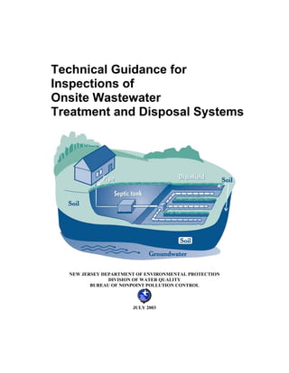
  • 6. Major Components of Onsite Systems In general, onsite systems include three components: Treatment Tank A treatment tank is a buried, watertight receptacle designed and constructed to receive wastewater from a building. Treatment tanks are designed to be either anaerobic (septic) or aerobic. The septic treatment tank's tranquil environment allows solids to separate from the liquids, provides limited digestion of organic matter, stores solids, and allows relatively clear effluent to discharge into the absorption area. The environment in an aerobic tank is not tranquil. Air may be forced into the effluent, or mechanical agitation devices, pumps or impellers constantly, or at timed intervals, mix the effluent. A properly working aerobic tank yields a more thoroughly treated effluent that is both clearer and has fewer odors. Research has shown that multiple tanks or two compartment tanks are more effective in solids separation than a single tank with one compartment. If multiple tanks or a multi-compartment tank are encountered, all tanks and compartments must be evaluated. Distribution System The distribution system is the method by which effluent is conveyed from the treatment tank into the absorption area. The distribution may consist of a gravity delivery line to a distribution box, or to a tank with a lift or dosing pump, or to a siphon chamber. In the case of a cesspool system, there may be no distinct distribution system. Absorption Area This component is very important because it is the most expensive and most difficult component of an onsite system to correct. Absorption of the effluent into the soil is achieved through any one of the following: • cesspools • seepage pits • absorption beds and trenches • above grade mounds • soil replacement systems Except for cesspools, which are both treatment tanks and absorption areas, these are generally referred to as absorption areas. Inspectors should carefully determine the location, type, size and, if present, the liquid level within the absorption area. A completely saturated absorption area will accelerate organic clogging and could eventually result in an absorption area malfunction, but should not be described as unsatisfactory in the report. In order to complete an inspection, the absorption areas MUST be located. 4
  • 7. Sequence Following all of the steps outlined herein, in order, is critical to the effective application of the standards when conducting an onsite system inspection. Sequence provides a uniform method of collecting information, which provides consistent inspection results between various inspectors and can be useful in cases where additional investigation is needed. However, since it is impossible to predict what can be present during any given inspection, if a deviation from the process is necessary to more thoroughly complete the inspection, that deviation should be noted in the report. The Inspection Form attached to this document contains the minimum information that should be identified during the inspection. It should be used in conjunction with these guidelines when completing an onsite system inspection. Obtaining Authorization It is recommended that a signed inspection authorization form be secured from the owner of the property or their authorized agent before gathering any information. See Appendix 1 for a sample authorization form. NJ One Call Contact NJ ONE CALL at 1-800-272-1000 to request that any utility lines be located at least 72 hours prior to the inspection. NOTE: This will not identify owner-installed utilities such as the onsite system or electric lines to pumps. 5
  • 8. Gathering Preliminary Information Regarding the Subject System General System Information As much information as possible should be gathered in advance of a site visit. Any information not gathered in advance should be gathered at the site. Prior to the inspection, the inspector or his agent should review records from the local administrative authority regarding the system. Health departments should be contacted at least 48 hours, during normal working days, prior to the inspection to allow enough time to provide for this file review. If records are not available, a letter from the health department or a notation of the individual at the administrative authority, along with time and date, acknowledging that records do not exist for the facility, should be provided in the report form. Requirements or fees for requesting a file review may vary based on jurisdiction. The inspector should also ask if there are any filing fees required by ordinance associated with submitting the inspection form to the local administrative authority, as required. During this file review a site plan (8½”x 11” or 8½” x 14”) with the location of the onsite system should be made for the report, if available. Additionally, the following items should be addressed during the health department file review, requested from the homeowner prior to the inspection, and compared to the information gathered during the inspection. 1. Type and age of onsite system(s) being inspected. 2. Age of structure. 3. Number of bedrooms 4. If occupied, what is the current number of occupants? If vacant, how long? What is the expected number of occupants? 5. Is a garbage disposal in use? 6. Request a copy of the system permit or a site sketch from the owner. 7. Is there evidence of a sewage back-up in to the house? If the structure has been unoccupied for more than one week, or the structure is subject to seasonal use or noncontinuous use, then in addition to the inspection, a Hydraulic Load Test should be conducted. 8. Is there a separate gray water system? 9. Is the washing machine drain line connected to the onsite wastewater treatment system? 11. Date of last treatment tank pumping? Frequency of treatment tank pumping? 12. What commercial or high water use activities or hobbies take place in the structure? 13. What prior repairs were made or problems encountered? 14. Are there any sump pump discharges to the system? 15. Are there any sewage discharges that bypass the system? 16. Has an inspection been conducted on the system previously? Date and results of last inspection? 17. Location information regarding the subject property should be obtained at this point. Be sure to collect municipality information (see a listing of municipalities at http://www.state.nj.us/health/lh/directory/lhdselectcounty.htm), Tax map Block and Lot information and provide any available coordinate data (GPS, lat./long., etc.). 6
  • 9. Procedures for Conducting the Field Investigation Inspections conducted when the subject property has been impacted by precipitation events, including but not limited to; rainfall; snow melting; or when the ground is snow covered, the inspection results must specifically identify the encountered condition and discuss the relationship of precipitation to the results of the inspection. General The field portion of a NJDEP onsite system inspection should be conducted in the following sequence. At all times the technician's personal safety, as well as protection of the environment and the client, shall receive the highest priority. 1. Note the weather at the time of inspection. 2. During the site visit, walk the entire house looking for unexpected fixtures, plumbing or discharges and exterior property looking for lush vegetation or discharges on or through any of the following: the surface of the ground, streams, road ditches, storm drains or unexpected pipes. 3. Note if trees, shrubs, their roots or any other landscaping features have been located above any system component or within ten (10) feet of the absorption area that could possibly create a negative impact the system. 4. Create a site sketch. Be sure to indicate distances of the treatment tank lid from two fixed points so that it will be easy to relocate the lid in the future. Do this for a distribution box as well if one has been located and accessed. 5. Be alert for above-grade evidence of a well. If a well is observed, note its location in the field notes and on the site sketch. 6. Compare the information gathered onsite to the information gathered previously and note any discrepancies. 7. Locate and gain access to the treatment tank(s), either initially or as indicated below and determine their composition. Check for infiltration of surface water into all tanks. Then locate the other system components. 8. A list of all subcontractors used during the inspection should be provided in, or as an attachment to, the report form. Inspection of the Internal Plumbing By providing an inspection of the internal plumbing, the inspector can obtain valuable information regarding where the building sewer discharges to the treatment tanks and can aid in the identification of the presence of multiple systems. This is especially important in confirming if the laundry facilities discharge to the septic system or to a separate system. Although this part of the inspection is significantly limited to where the plumbing is exposed, as in the case of unfinished basements, it should be attempted at dwellings with finished basements and elevated crawl spaces. However, due to interior finishes or impeded access, an inspector may elect to waive this portion of the inspection in dwellings with finished basements or crawl spaces with a notation in the report as to the conditions of why the inspection was not completed. If the inspection involves a dwelling on a slab foundation, this portion of the inspection may not be practical and may be waived by the inspector. 7
  • 10. Minimum Inspection Criteria 1. Review the existing septic system location documents. Confirm the number, size and general exit point(s) of the waste lines consistency with the system location documents and note any deviations. 2. Observe the general location of the plumbing fixtures within the dwelling to be reasonably sure you have determined that all waste line exit points and interior plumbing fixtures are reasonably accommodated. Discharge of a particular fixture may aid waste line identification during this procedure. 3. Observe the general condition and materials of waste piping, specifically within the stack. Differences in piping materials may be indicative of plumbing alterations necessitated by septic system failures. For example, a capped line that previously accepted the washing machine discharges. 4. Determine if any particular fixture can not reasonably be piped to the observed exit point. If any exist, dye should be used to confirm the discharge point for that fixture. Observation of the effluent within the first septic system component should occur to confirm the colored discharge. If the colored discharge is not observed, further investigation of the discharge point is required and shall be noted as such. 5. Determine if a sump pump services the residence. If one exists, confirm the discharge point of the sump is separate from the domestic waste lines and that the domestic waste is not directed to this equipment. Treatment Tanks General Generally, tanks should not be entered, as they are hazardous environments. If entry is required, appropriate safety measures and equipment consistent with OSHA requirements must be employed. During the initial investigation to locate the treatment tank, be careful to avoid damage to the tank and any Aerobic Tank buried electrical wires. The inlet and outlet baffles should be thoroughly inspected; however, the inlet and outlet baffles are somewhat susceptible to damage and must be treated with caution. The baffles help protect the absorption area from solids carryover. If deteriorated or missing, they should be repaired or replaced and the client should be notified of the potential problems associated with the ability of increased solids being allowed to enter the absorption area. Treatment tanks are generally comprised of one of three different materials and you should inform the client directly of the material of the tank. Concrete tanks are generally sound as compared to tanks of other materials. Metal treatment tanks have an average life expectancy of 20 to 25 years. Plastic or fiberglass tanks resist deterioration; however, they are susceptible to puncture by a probe rod. Extreme care should be used during the initial probing when locating tanks of this nature. 8
  • 11. Minimum Inspection Criteria 1. A satisfactory liquid level occurs when the liquid level is below the inlet invert and equal to the height of the outlet invert. If a treatment tank is overfull, you should determine whether the problem is in the distribution system or in the absorption area. 2. Scum thickness and sludge depth should be evaluated through the main access port by using a Sludge Judge, Sludge Stick or similar device. Do not pump any treatment tank until the absorption area has been investigated and should proceed at this point. The decision of when to pump a treatment tank is based on the absorption area's condition. These criteria determine when to pump the treatment tank(s): • If the aggregate in the absorption area is fully saturated, do not pump the treatment tanks. It is important to leave the existing system alone so that the results can be field verified if necessary. • If the water level in the tank is above the outlet invert and the liquid level is less than the full depth of the aggregate, investigate cause of blockage. • If the operating level in the tank is normal and the aggregate is free of liquid or the liquid level is less than the full depth of the aggregate, pump all tanks. 3. Pump all treatment tanks and compartments using the main access (largest opening) for cleaning, if accessible. Inspection ports should not be used for pumping. Septage should be removed, at a minimum, to within two inches of the tank bottom. Identify on the report and notify the client when sewage flows into the tank from the drainage area or if any defective septic system components are observed. 4. As each tank is pumped, look for inflow, cracks, holes and deficiencies that are hidden below the surface, including the tank bottom, and describe any of these in detail in the report. 5. Verify that all fixtures' discharges are entering the treatment tank. 6. Flush every toilet in the structure at least once. Use the observation port over the inlet or main access to note changes in treatment tank's liquid level (or observe backup conditions). 7. Check for continuous flow through the building sewer and into the treatment tank. 8. Insert a mirror on a 45-degree angle through the main manhole and inspect the underneath side of the tank top while shining a flashlight on the mirror. Determine the treatment tank's construction, composition (material), and condition of the tank, the baffles, and the cover. Determine the tank's capacity. Do this for every tank in the system. 9. Determine whether or not the tank is deteriorating and in need of replacement. 10. Check the baffles in every compartment by inspecting them directly through the inspection ports, or by using a mirror and flashlight through the main access port of the treatment tank. 11. In the case of an aerobic treatment tank, the electrical and mechanical operation of the pumps and compressors should be checked by observing them in operation. If you are not familiar with these tanks, contact someone who is. No NJDEP Inspection is complete until every tank is pumped and its condition evaluated. 9
  • 12. Holding Tanks General Since 1990, holding tanks are generally prohibited by New Jersey regulation, unless a sewer connection will be available within 180 days of the tank installation as approved by the administrative authority or the system has received a Treatment Works Approval (TWA) issued by the Department. All holding tank systems, including those approved by a local administrative authority prior to 1990 systems should be evaluated using the following minimum steps: 1. Check to see if the holding tank has audible and visual alarms. The Department recommends that all holding tanks have these types of alarms. These alarms should be installed so they activate when the material in the tank has reached 75% of the tank's capacity. 2. Determine the tank’s capacity. The Department recommends that holding tanks have a capacity of a minimum of three days' design flow (as determined by the criteria in Appendix 7) or 1,000 gallons, whichever is greater. 3. Measure and record the liquid level; then pump all tanks and compartments. As each tank compartment is pumped, look for inflow, cracks, holes and deficiencies that were previously hidden below the liquid surface. 4. Determine the tank does not leak and is watertight. 5. Inform client of the increase in frequency of pumping and their financial responsibility for ongoing maintenance of that service. Dosing and Lift Pumps and Tanks and Siphon Tanks General Dosing and lift pump tanks and siphon tanks should be inspected for physical integrity, just as treatment tanks are inspected. Dosing and lift tanks house a pump which either simply transports (lifts) the effluent to another elevation or delivers a specific volume of effluent to a pressure distribution system at a specific pressure. Siphon tanks contain a proprietary device that operates on atmospheric pressure, and at a factory set "trigger depth," the accumulated effluent is moved downhill under pressure. Minimum Inspection Criteria 1. Always check the absorption area before turning on either a lift or dosing pump; however, if the pump has recently been activated, finish all aspects of the inspection before checking the water level in the absorption area. 2. Check the condition and soundness of all pump and siphon tanks, using the tank inspection procedures described previously, including the alarm system. 3. If the system has a pump or pumps, verify the operation of every pump and its control system. Use a rake, hoe or similar device to elevate the appropriate float and activate the various components. 4. Visually inspect exposed electrical cables, junction boxes, etc. Do NOT touch any electrical wires or components unless you have PERSONALLY de-energized the circuit. Verify that the alarm and pump are on separate circuits. 5. Verify that all pumps are resting on a concrete block and elevated above the tank bottom. Pumps should not be suspended. 10
  • 13. 6. For siphon pressurized systems, open the observation port and check for continuous trickling. Run sufficient water into the siphon tank to cause the siphon to cycle, and watch for proper operation. 7. Measure and record the liquid level; then pump all pump tanks using the main access (largest opening) for cleaning, if accessible. Septage should be removed, at a minimum, to within two inches of the pump tank bottom. As each tank is pumped, look for inflow, cracks, holes and deficiencies, including the tank bottom. Effluent Delivery and Distribution Systems General Effluent is conveyed to the absorption area through solid rigid pipe in a manner that will provide for equal distribution of the effluent through the absorption area. Effluent may be moved by gravity or by pump. Systems installed since the 70's have used thin wall plastic pipe as the material of choice. When the effluent delivery line passes under areas subject to heavy loads (driveways), it is common to either use a heavier grade of pipe (schedule 80) or encase the effluent delivery line in a larger diameter heavier grade pipe. Effluent delivery systems may include a lift pump. In these situations, the absorption area is at a higher elevation than the treatment tank. Lift pumps are sized to overcome the friction in the pipes and the effects of gravity. These forces are called "head." Unlike a dosing pump, there is no required minimum head at the terminal end. Gravity systems In gravity systems, the effluent should be distributed either to a number of trenches or through several interconnected lines in an absorption bed. A distribution box (D-Box) is a small, usually concrete, container that most often receives effluent from a connecting pipe. Lift pumps can also discharge effluent to a D-Box. The D-Box has one inlet and several outlet ports. The outlets are at least one inch below the inlet's elevation. A variety of devices can be used to fine-tune the effective outlet elevations so that all lines receive an equal volume of effluent. A D-Box MUST be used to divide the flows in ALL gravity trench systems. A D-Box may be used to divide the flows to the laterals in a bed system. The D-Box should not be inside a trench, however, it may be found either outside or within the bed area. When found, the location of the D-Box should always be noted. Pressure systems Pressure distribution systems use a pump to assure equal distribution of the effluent across an entire absorption area or system. In a pressurized distribution system, a pump delivers effluent to a manifold, which in turn supplies a series of somewhat smaller diameter laterals. Pressure distribution may be encountered in all system types. 11
  • 14. Minimum Inspection Criteria 1. Distribution systems are checked by examining the treatment tank's outlet. If the liquid level is above the lowest point of the outlet of the treatment tank, further investigation is needed to locate and evaluate the cause of this condition. 2. If a D-Box is found and exposed, it should be evaluated; if a D-Box is not found, the absorption area investigation should proceed. However, if known to exist, the location of the D-Box should eventually be established on the site sketch or a notation that further investigation would be needed in order to locate the D-Box. 3. When a D-box is located and exposed, check for the presence of solids. All solids should be removed from a D-box, if present, and a notation of their presence should be noted. The structural integrity of the D-box should then be evaluated for any significant defects or deterioration. D-boxes must be watertight and not leak effluent or have exterior leakage into the component. Make sure the D-box is level and/or that effluent is equally distributed to the laterals. Absorption Area Types, Sizes, and Conditions - Subsurface Systems Overview The absorption area is the most critical component of an onsite system. No system report should be issued (other than "more investigation necessary") if this component is not found. If the inspector observes or has reason to believe that the system is discharging directly to the surface of the ground, or to the surface or ground waters of the State of New Jersey, such conditions shall be noted and the system shall be described as unsatisfactory. Cesspool or Seepage Pit General Cesspools and seepage pit systems that receive blackwater no longer meet current regulatory code for new construction, however these systems may continue to exist if they are operating as designed. Seepage pit systems that receive greywater only are currently permitted for existing and new systems. Cesspools receive all of the structure's flows directly (solids and liquids); seepage pits are preceded by a treatment tank where the solids are separated from the liquids. Any cesspool system that has malfunctioned, as declared by an authorized administrative authority (health department), must be (or have been) upgraded. Minimum Inspection Criteria 1. Determine the structure's capacity; then measure the distance from the water level to the bottom of the inlet pipe. For seepage pit systems, if liquid is at or above the inlet invert, the high water condition SHOULD be noted. For cesspool systems, if liquid is at or above the inlet invert (i.e., the building sewer), the system is unsatisfactory and the observed non-compliance requirements shall be met. 2. Determine daily flow using N.J.A.C. 7:9A Standards. (see Appendix 7) 3. Determine the available storage capacity in the seepage pit or cesspool below the bottom of the inlet pipe. 4. Determine if there is capacity for one day's flow. Confirm there is at least one day’s storage capacity available below the bottom of the inlet pipe to the seepage pit or 12
  • 15. cesspool. If there is less than one day's capacity, the high water condition should be noted. 5. Evaluate the liquid, scum and sludge levels; then pump the cesspool or seepage pit. Look for deficiencies and excessive inflow. 6. If a system has both a cesspool and an absorption area, evaluate each component separately. Inlet and outlet baffles to the cesspool are not required, however if there is an additional drainage system, outlet baffles to that system are recommended. Subsurface Bed or Trench Systems General Seepage beds are usually rectangular excavations that are partially filled with aggregate in which a network of perforated pipes distributes the effluent throughout the bed area. Trenches are long, narrow rectangles from 1.5 to 3 feet wide. Trenches are usually of equal length, partially filled with aggregate, in which a perforated pipe distributes the effluent throughout the length of the trench. Effluent is delivered to the trenches either under pressure (pump or siphon delivery) or by gravity. Serial distribution, which has not been allowed for new construction projects since 1990, directs all the effluent to a series of trenches that are "stepped down" a sloped site. After the first trench fills, the effluent "overflows" into the second; when it fills, the effluent again overflows into the next lower trench, and on. Gravity supplied trenches receive effluent from a common distribution box (D-Box). All trenches should receive an equal volume of effluent and their individual conditions should be similar. If not, further investigation is necessary. Cover over the aggregate material may vary greatly. After final approval, additional fill and surface grading may take place, consequently, the absorption area may be at a greater depth than anticipated. Above-grade systems: Mounded and Mounded Soil Replacement Systems A Mounded System or a Mounded Soil Replacement System is usually a bed type distribution system built on top of suitable fill material. In both systems, the fill provides both a level surface upon which the aggregate is placed and a porous filtering material for effluent renovation. In both systems, fill and aggregate are contained within a berm of suitable soil and the aggregate is above the site's preconstruction grade. In both systems, the cover over the aggregate is graded to direct precipitation away from the mound. In Mounded Systems, the entire system, fill, aggregate, and cover are all placed on the site's original soil. In a Mounded Soil Replacement System, a portion of the original site is excavated and backfilled with suitable fill which extends above the original grade. The fill is leveled and the system built upon that suitable fill material. In all of these absorption areas, a piping system distributes the effluent throughout the aggregate. These systems may distribute the effluent either by gravity or under pressure using either pump or siphon delivery. 13
  • 16. The berm supports the aggregate and suitable fill; it also contains the effluent and directs its downward movement (vertical and/or downslope) within the berm footprint. Soil Replacement Systems: Bottom Lined and Fill-Enclosed Systems There are two variations of the soil replacement system. Both rely on a trench or bed absorption area that is installed on suitable fill material. For both, the soil cover depth varies greatly. In the Bottom Lined Systems, the area directly under the aggregate is excavated, then filled with suitable fill material that is leveled. The aggregate is placed on the fill's level surface. Although called a "lined" system, there is no enclosing impervious layer installed in this system. In the Fill-Enclosed System, an area that is larger (longer and wider) than the aggregate foot print is excavated, then filed with suitable fill material that is leveled. The aggregate is placed on the fill's level surface. The suitable fill material that extends beyond the aggregate footprint is brought up to the same elevation as the aggregate's finished grade. Interceptor Drains On sites where a perched zone of saturation has been identified, an interceptor drain may be utilized to capture and move subsurface water (perched groundwater) around the system. These drains typically resemble a "squared U" where the closed bottom is upslope and parallel to the longest dimension of the absorption area. The ends of the U will extend downslope some distance below the lower sides of the absorption area and will be brought to the ground's surface. Do not mistake these drains as a source of surfacing effluent as their intended purpose is to move and discharge ground water. Minimum Inspection Criteria for all Subsurface Bed or Trench Systems 1. Determine the type, location and approximate size of the absorption area. 2. Determine if there is standing liquid in the absorption area by probing or other means available. If so, measure the depth of the effluent throughout the absorption area. Measure the difference between the liquid's depth and the invert of the laterals at the D- Box/manifold or the base of a lateral as best determined by the inspector. This depth (distance) is called the "dry aggregate." Do not use inspection ports for this evaluation. If inspection ports are present, make a note of their presence, locate them on the site sketch and provide liquid levels below the ground surface in the report (in inches). However, a sufficient number of probes should be made in each absorption area by the inspector to make a complete absorption area evaluation. If there are six or more inches dry aggregate below the invert of the laterals, the absorption area is satisfactory. If there are less than six inches of dry aggregate, the high water condition should be noted. 3. When liquid is present in an absorption area, it should be of an equal depth and evenly distributed throughout the entire bed. If it is not, further investigation is necessary. Possibilities include, but are not limited to: • The bed may not have been excavated with a level bottom. • Sludge may be clogging the aggregate or soil interface. 14
  • 17. A pipe may be crushed, clogged, broken; or • The D-Box was not properly installed or has settled out of level. Minimum Additional Inspection Criteria for Trench Systems 1. In serial distribution systems, if a lower trench is full but higher trenches are not, further investigation is necessary. 2. In gravity supplied trenches, check to make sure the trenches receive effluent equally from the D-Box and the subsurface conditions encountered during probing should be similar. If not, further investigation is necessary. Minimum Additional Inspection Criteria for Mounded Systems 1. Probe the aggregate in either of these mound systems in the manner described above. Note if standing liquid is present. The condition determination is the same for these systems as subsurface systems. In New Jersey, the presence of effluent in the suitable fill is not an unsatisfactory indication. If the fill is saturated, the system is described as satisfactory. As stated previously, do not use inspection ports for this evaluation. If inspection ports are present, make a note of their presence, locate them on the site sketch and provide liquid levels in the report, however at least one separate probe in the absorption area should be completed to make the overall system evaluation. 2. Examine the mound for: • Leakage on the top, side slopes, and toes • Sufficient depth of soil cover at the top edges • Animal burrows, deeply rooted vegetation and erosion For all systems: If the absorption area is completely saturated, do not pump the treatment tank. If the aggregate is saturated to its entire depth, do not conduct a hydraulic load test. NOTE: If the absorption area is satisfactory and the treatment tank access has not yet been exposed, access should now be achieved and all steps in Treatment Tank Procedures (above) should now be completed or performed. The probing and effluent level exploration process is the same for all systems, including Infiltrator and similar gravel alternative systems. Serial distribution systems should not experience liquid in the lower trenches while there are unsaturated upper trenches. Regardless of system type, careful notetaking is necessary. In New Jersey, absorption areas can be either fully above, fully below or partially above and below the site's prevailing grade. The Hydraulic Load Test A hydraulic load test is a method to evaluate a disposal area by adding clean water to the system and observing what happens to the water levels beneath the disposal area. The inspector may 15
  • 18. recommend that a hydraulic load test be conducted to determine if the system is properly functioning when any of the following observations are made: 1. High water condition 2. Structure vacant for more than 7 days 3. New water sources directed to the system within last 30 days 4. Soil fracturing activity within last 30 days 5. There is less than 24 hours storage capacity in a cesspool or seepage pit 6. Evidence that the treatment tank has been recently pumped 7. There is a significant difference in the current water use in a structure compared to the anticipated use of the structure When a hydraulic load test is recommended to a client, the inspector should describe why the recommendation is being made and what the test will entail by detailing the procedures and the possible results of the test. The client may elect not to proceed with the test, but the inspector should secure a signed release from the client acknowledging that the test was recommended, but refused prior to the release of the report to the client or their representatives. Any notification to the administrative authority should be completed as indicated. If the test is refused, the concerns should be outlined on the final report. However, any refusal should not be construed as an incomplete inspection. The client may simply not wish to persue with a home sale if the indicated problems or any other problems encountered are outside their expectations of negotiation. Alternatively, the client may wish to proceed with negotiations without knowing the full extent of the liability. Appendix 5 provides a hydraulic load test example that will satisfy the conditions of an inspection. To be considered a NJDEP Inspection, any hydraulic load test which does not follow the methodology in Appendix 5 should be designed and sealed by a New Jersey Licensed Professional Engineer. The test should thoroughly evaluate how liquid levels in a disposal area react to an appropriate volume of introduced clean water. Accessory Components Any accessory component of the system, which can range from items such as an effluent filter to an aerobic treatment unit that was installed in addition to an otherwise conforming system, should be noted on the form. By definition, an accessory component is something added to a system, which does not otherwise affect the system’s operation as a conventional disposal system. These accessory components should only be inspected by an inspector that is familiar with that specific type of component. Alternative or Innovative Technologies Any system using alternative technologies or innovative technologies as part of the system may only be inspected by personnel trained or otherwise familiar with the specific technology present. Many systems that are approved for use in New Jersey are required to have inspection forms and protocols available through the manufacturer. Those forms and protocols should be obtained prior to the inspection. Many systems using these technologies are required to maintain service contracts for the systems. A review of the homeowner’s service records, contacting the maintenance provider and the manufacturer of the equipment should all be made part of the 16
  • 19. inspection. An estimate of the annual cost of operating the system and maintenance agreements should be included in the report. 17
  • 20. Preparing the Inspection Form and Report Reaching Conclusions about the System The following sections present decision points that will enable the inspector to draw conclusions regarding the system under investigation. There are four potential conclusions: • More investigation is necessary to reach a conclusion • Satisfactory • Satisfactory with concerns • Unsatisfactory In addition to these conclusions that could apply to all components, one conclusion may apply solely to the absorption area: • Water level less than six inches below the invert of the laterals or high water condition If this condition is observed, regulations prohibit concluding that the observed water levels above the invert elevation of the laterals are a manifestation of failure. For further guidance regarding this observation, review the “Concerns” section below. If the high water condition is noted, the inspector should explain the significance of this condition and may recommend a hydraulic load test, which is a valuable tool in assessing the significance of the high water condition. Any concern or unsatisfactory conclusion reached regarding an onsite system that requires further action must be resolved or negotiated between the buyer and seller. It is not the responsibility of the local administrative authority or NJDEP to resolve the financial or legal responsibility of resolving these items of concern. In addition to the above conclusions, certain unsatisfactory observations should be reported to the local health department within 24 hours of the inspection. These observations include: • Ponding or breakout of sewage or effluent onto the surface of the ground. • Seepage of sewage or effluent into portions of buildings below ground. • Backup of sewage into the building served which is not caused by a physical blockage of the internal plumbing. • Any manner of leakage observed from or into septic tanks, connecting pipes, distribution boxes and other components that are not designed to emit sewage or effluent. These factors and thorough site notes enable a conclusion about every component in the system. If a component is found to be unsatisfactory, the system is unsatisfactory until the component is repaired or replaced. 18
  • 21. More Investigation Reasons for additional investigation and further evaluation can include, but are not limited to: • Absorption area can’t be located with tools on-hand. The absorption area MUST be located and investigated in an NJDEP Inspection • Pump discharge is inadequate • Less than 24 hours volume capacity in cesspool or seepage pit (note the high water condition) • Structure vacant more than 7 days (conduct a hydraulic load test) • Unequal distribution within absorption area (find distribution box) • Overfull treatment tank (liquid level above inlet) when the absorption area is satisfactory • Signs of previous unsatisfactory performance, including: - stains in soils adjacent to treatment tanks, on surface, etc. - stains or water level marks on treatment tank walls; debris on tank ceiling - stains at top of aggregate - sludge in aggregate • Deterioration of concrete components • New gray water sources directed to the system within last 30 days (note the high water condition) • Soil fracturing activity within last 180 days • Lush vegetation at or near the absorption area • Unexplained pipe to stream, road ditch, storm sewer, etc. • System has no discoverable absorption area; additional exploration is required to locate it • If there is less than six inches of dry aggregate below the invert of the laterals, note the high water condition • Signs of a second or separate gray water disposal system that was not inspected • Septage odors emitted from discharges of interceptor drains or basement sump pumps • D-box could not be located Concerns These factors are worthy of note when determining a satisfactory system. They should be included in the Inspection Report and brought to the client’s attention. The client should draw their own conclusions regarding the effect these factors may or may not have on the system under investigation. • High water condition was observed. This observation of water within six-inches below the inlet elevation of the laterals is an indication of impeded drainage within the disposal area. 19
  • 22. The closer the water levels approach the laterals, or encompasses them, the more substantial the concern. While this observation is not a failure, it is an indication that the system may be nearing the end of its serviceable life and may require corrective measures in the near future. The current or future homeowner may wish to conduct water use monitoring, reduce water use and/or find a physical remedy to correct the condition. • Solids level above 1/3 of tank’s liquid capacity • No/low levels of solids with no record of recent pumping. • System age • Systems with poor/no maintenance history • Access ports greater than 12” below the finished grade • Sludge level in pump tanks within three inches of the pump inlet • Soil fracturing or chemical injection has been used to remediate the septic system regardless of the results of a hydraulic load test. These remedies are temporary in nature and indicate potential problems with the continued operation of the system • Cesspools or seepage pit systems passed hydraulic load test but has less than one day’s storage available. • Number of bedrooms in the administrative authority approval that was the basis for the system design and approval is less than the number of bedrooms present or being represented as readily available to the inspector • Constant flow through building sewer from structure served regardless of satisfactory condition of the balance of system • Indirect sump pump, footer drains, roof and downspout discharges to the surface areas where the onsite wastewater treatment system is located Unsatisfactory Reasons for concluding a system is unsatisfactory include, but are not limited to: • Ponding or breakout of sewage or effluent onto the surface of the ground. • Seepage of sewage or effluent into portions of buildings below ground. • Backup of sewage into the building served which is not caused by a physical blockage of the internal plumbing. • Leakage into tanks, access or observation ports, or leakage from any component which was not designed to leak (such as an absorption area) into the environment • Treatment tank baffles are damaged or missing • Physically deteriorated components (concrete or metal tanks, etc.) • Clogged or broken effluent delivery lines or other pipes • Non-functioning electrical component (aerobic device, pump, controls, alarms, etc.) 20
  • 23. Effluent or gray water on the surface of the ground or observed to be discharging to the waters of New Jersey • Any sewage or effluent entering the structure (through pipes or seepage through the wall) • A well is present in the absorption area, or any direct discharge of effluent or sewage to a well, bore hole, natural or man-made cavern or cavity, or sink hole is observed • Direct sump pump, footer drains, roof and downspout discharges to the onsite wastewater treatment system • Plumbing fixtures were dye tested and ultimate disposal location could not be determined. Corrective Measures Potential corrective measures that may be negotiated between the buyer and seller if agreed upon include, but are not limited to: • Replace or repair tanks, baffles, pipes, etc. • Repair or replace electrical components (lift or dosing pump, alarms or controls) • Repair or replace aerobic treatment units, filters, etc. • Install a new absorption area • Eliminate points of infiltration • Install water conservation devices • Evaluate existing water use data, if available, and compare to existing design flow and projected future use. • Reduce loading to the disposal area by: • Relocating illicitly connected discharges to acceptable locations (i.e., sump pumps, downspouts, etc.) • Check for backwash or water treatment discharges and redirect to separate greywater or seepage pit disposal systems. • Install water saving devices The client should be cautioned and instructed to contact the administrative authority for guidance regarding the permit application process, parts replacement or repairs. Following completion of repairs, inspectors should verify that the concerns or unsatisfactory conditions were corrected and summarily documented. Notes on Completing the Inspection Form The inspection report may be the completed Inspection Form. No additional written document is required regarding the system’s condition, but is recommended in order to clarify the issues surrounding any concerns or unsatisfactory conditions. The form provides the client with information regarding the type and overall condition of the system, a statement of any problem(s) found, and suggested corrective measures. All inspection reports and forms should be prepared, signed and dated by the inspector that conducted the field investigation. 21
  • 24. Based on your notes, create a site sketch. Be sure to indicate distances to the treatment tank lid and D-box (if located and accessed) from two fixed and permanent points so that it will be easy to relocate the system’s components in the future. The client should be notified that the site sketch is approximate and for reference only. The sketch can not serve as an engineered or surveyed plan as a basis for future site work (such as installing additional utilities or expanding the building structure). Based on your notes regarding the treatment tank, distribution system, absorption area, pumps and electrical components determine a condition for each component. Select from: • Satisfactory • Satisfactory with concerns • Unsatisfactory • Condition cannot be determined; additional investigation is needed • Not Applicable (N/A) – the component does not exist in the inspected system The report should indicate the condition of each component. If more investigation is needed, indicate the component to be investigated, the nature of the investigation to be undertaken and an estimated cost. A copy of the inspection form should be provided to the administrative authority having jurisdiction over the onsite wastewater disposal system within 10 days of the inspection. If a condition is observed that requires immediate attention of the administrative authority, notification of the observation should be provided within 24 hours of the inspection. Although you may wish to include any additional reporting information for clarification purposes, it is not required. 22
  • 25. Appendix 1 - Sample Inspection Authorization Form On your company letterhead XYZ Inspection Services Company 123 Anywhere Road Yourtown, NJ Re: Client name Property owner Client mailing address Property address City, St., Zip City, St., Zip Directions to property Sir/Madam: Authorization In regard to the above described property, the signature below authorizes and this letter instructs the above named Company to undertake and perform the following: [Include only those that are applicable, or provide a comprehensive list with an X or client’s initials for each selected item.] - enter the property described - inspect and report on the onsite wastewater treatment system, which includes pumping of all tanks - contact/interview local officials to review environmental and construction records - contact/interview previous inspectors - contact/interview maintenance providers which have worked on the property Professional Fee I understand the fee for the services indicated is: $____________, which includes up to ____ hours of inspection activities by an inspector. Due to unforeseen circumstances, additional work may be required to complete the inspection. The Company will advise the undersigned of the estimated additional costs before proceeding. Terms of payment are _________. Performance Standards The work will be performed in a good and professional manner by the Company in accordance with applicable current onsite wastewater treatment system Inspection Standards (Standards) adopted by the New Jersey Department of Environmental Protection. Report is Not a Warranty The undersigned understands and acknowledges there are numerous factors, which affect the installation, operation and maintenance of onsite wastewater treatment systems. The inspection and the Inspection Report to be issued shall not and will not constitute, and shall not be construed by the undersigned, as a warranty by the Company that the system will function properly for any period of time or for any particular loading or usage. The undersigned understands and acknowledges that the Report will present conditions observed on the date and 23
  • 26. at the time of inspection. The undersigned will not represent the report as a warranty to third parties. Disclosure of Report and Findings The Company is authorized to disclose the results of the inspection and any and all records relating to the system’s installation, repair or maintenance history to (if no one, indicate no one): ____________________________________________________________________________. At a minimum, a copy of this report should be filed with the local administrative authority (health department) within 10 days of the date of the inspection. If any condition is observed during the inspection requiring a 24-hour notification to the local administrative authority, that notification will be made as required by the inspector. If any other applicable law, regulation or ordinance requires that the report be filed with or submitted to a state or local agency, or other person, the undersigned acknowledges and agrees that the undersigned property owner or agent shall make such a submittal, and if the requirement to file such report rests upon the inspector, the undersigned agrees that such submittal shall be made. Accepted and agreed to this date ___/___/___ By __________________________________ Property Owner/Owner’s agent Optional elements you may want to include: • Name of a company representative that the client can contact • Preliminary Information Form for the client to complete • A breakdown of the buyer’s and seller’s obligations (costs) 24
  • 27. Appendix 2 - Sample Inspection Report Letter (Recommended) On Your Company Letterhead Date Name Street Number City, State, and Zip Re: Onsite Wastewater Treatment System (Site address if other than above) Dear (client’s name): As requested, this company inspected the onsite wastewater treatment system at the above address on (date). This letter provides you with a report of the inspection. Based on the preliminary information you provided and the field inspection, (Satisfactory) We found the onsite wastewater treatment system to be in a satisfactory condition on the date it was inspected. (Satisfactory with Concerns) We found the onsite wastewater treatment and disposal system to be satisfactory on the date it was inspected. However, there are some items about which we have concerns. They are: (List concerns) (More investigation needed) We are unable to verify that the onsite wastewater treatment and disposal system is presently in satisfactory working condition for the following reasons: (List reasons) (High water indications) Standing liquid in the absorption area was observed within six inches below the inlet invert of the laterals. The NJDEP “doesn’t recommend concluding that observed water levels above the invert elevation of the laterals are a manifestation of failure.” This observation of water within six-inches below the inlet elevation of the laterals is an indication of impeded drainage. The closer the water levels approach the laterals, or encompasses them, the more substantial the concern. The current or future homeowner may wish to conduct water use monitoring and/or reduced water use. While this observation is not a failure, it is an indication that the system may be nearing the end of its serviceable life and may require corrective measures in the near future. (Unsatisfactory) Corrective measures are required to bring the system into satisfactory condition. Some or all of the suggested activities may require a permit from the local agency administrative authority or 25
  • 28. health department. The administrative authority must be contacted and his regulatory guidance sought before undertaking any of these activities. (Hydraulic Load Test) A condition resulting in the recommendation of a hydraulic load test was observed during the site inspection. A hydraulic load test will be provided for a fee of $________ according to the attached guidelines. The performance of the hydraulic load test is not required, however it is highly recommended to determine the extent of the problems encountered. If the test is not conducted, a signed release statement should be provided by the client prior to the release of this inspection or any of the information contained herein. (Observed conditions required to be reported within 24 hours to the local health department) Conditions were observed at the time of the inspection that the New Jersey Department of Environmental Protection requires to be reported to the local health department within 24 hours of the observance. The __________ (health department) was notified via (fax/telephone/hand delivery/etc.) of the condition and will respond appropriately. At the completion of repairs, a follow-up inspection by our company is needed to insure that the system has been restored to a satisfactory condition. (List suggested activities) This is a Report, Not a Warranty The Company provides no warranty, express or implied, including any warranty of merchantability or fitness for purpose, or any other warranty whatsoever, that the system meets any code or specifications, or will function properly for any period of time whatsoever, or otherwise will not malfunction or cause contamination of the ground or waters of the state of New Jersey. A copy of the field data upon which this report is based is available upon request. Sincerely, Inspector’s name & signature Company 26
  • 29. Appendix 3 - Additional Suggested Comments for Inspection Reports Preliminary Information Weather • It should be noted that due to the drought, soil moisture levels are extremely low which can cause septic system operation to appear more favorable than under non-drought conditions. • Excessive rain during the prior 72 hours may effect the water level in the drainage area. • Snow accumulation prevented/inhibited surface observation of the disposal area. • Due to extended cold weather and frozen ground conditions, certain system components could not be identified or located. • A lawn irrigation system should not be located in the area of any septic system components because it could hydraulically overload the system and lead to premature malfunction. Age of System • This type of system is permitted for an existing use, but it does not meet current construction standards and The Company cannot predict the system’s remaining serviceable life. Systems older than twenty years are beyond their peak operating efficiency and are likely to require repair or replacement. Please read the disclaimer on the last page carefully. • This type of system is permitted for an existing use. However, it does not meet current construction standards and The Company cannot predict the system’s serviceable life. Please read the report disclaimer carefully. • Like other components of a home, a septic system has a limited serviceable life span. Systems designed prior to 1990 may not meet current standards, may be past their peak operating efficiency, yet function at the time of inspection. Please read the disclaimer on the last page carefully. • Like other components of a home, a septic system has a useful life span. Systems older than twenty years generally do not meet current standards are beyond their peak operating efficiency and are likely to require repair or replacement, even if they are functioning at the time of inspection. Please read the disclaimer on the last page carefully. Number of Bedrooms • The current number of bedrooms identified is greater from that identified by construction approval. As a result, the system that was approved by the local administrative authority was not appropriately sized for a residence containing the number of bedrooms present. It is not possible to predict how the system will perform given an increase in occupants. 27
  • 30. Commercial Activities and/or High Impact Hobbies • Commercial activities and certain hobbies may place excessive hydraulic loading on the system, which may result in the discharge of undesirable substances into the septic system. Repair History • This is a re-inspection after an outlet pipe blockage was cleared. Outlet blockages are typically caused by solids carry over from the treatment tank. Water is now flowing freely to the drainage area, however The Company cannot ascertain how much, if any, sludge made its way into the drainage area. • There have been significant alterations made to the system, which are not consistent with health department records. The Company cannot verify that the system was repaired according to health department standards or if the alterations have adequately corrected any problems. Occupants • All aspects of the septic system were in satisfactory condition at the time of inspection. The water use by the current number of occupants (_) is substantially lower than the design rate for a five bedroom home, and the anticipated water use of the new occupants (_) will be significantly higher and it is not possible to predict how the system will perform given this increase. • The drainage area is near its maximum capacity with the current water use. Any additional occupants or higher water usage may cause a system overload. Due to limited occupancy (____ resident(s)) normal hydraulic loading on the system could not be duplicated. A hydraulic loading test may be used to further evaluate this disparity. • The system was functioning at the time of inspection with the volume of water used by the current number of occupants (_). That typical volume is substantially lower than the design rate for the home (_ bedrooms) and normal hydraulic loading cannot be duplicated. The Company cannot predict how the system will operate if the number of occupants or water usage increases. A hydraulic loading test may be used to further evaluate this disparity. • Due to the length of vacancy, normal hydraulic loading on the drainage area could not be duplicated and The Company cannot predict how the system will function when the home is occupied. A hydraulic loading test may be used to further evaluate this disparity. • The property was vacant at the time of the inspection. As explained during the inspection, normal hydraulic loading on the drainage area could not be duplicated during the inspection. The Company cannot predict how the septic system will function when the property is occupied. Please read the report disclaimer carefully. • The Company recommends that systems not in use for an extended period or minimally used, have a hydraulic load test, for a more conclusive examination of the drainage area. 28
  • 31. Disclaimer: • I have read and understand The Company hydraulic load test protocol. I authorize The Company to perform a septic system inspection without hydraulic load testing. • Customer read and understood The Company vacant property hydraulic load test protocol and declined hydraulic load testing • Due to the length of vacancy, normal hydraulic loading on the drainage area could not be duplicated. Please read the report disclaimer carefully. Washing Machine • The washing machine is discharging onto the surface of the ground, which is prohibited by New Jersey Administrative Code. The washing machine discharge should be re-directed into the septic system or into a separate seepage pit system to reduce the hydraulic load to the septic system, extending its serviceable life. Garbage Disposal • The kitchen is equipped with a garbage disposal unit, which will increase the solids content being loaded into the septic tank. The use of garbage grinders is not recommended for use with septic systems, but if used regularly, more frequent tank pumping is needed. • Garbage disposals place a higher level of suspended solids loading on the septic system. The septic tank should be pumped at a greater frequency/annually. Maintenance History • The treatment tank has not been adequately maintained. There are excessive solids in the tank and solids carryover into the drainage area is likely. Date of Last Pumping • The septic tank was pumped one week prior to this inspection. The septic tank had not reached operating level at the time of this inspection and normal hydraulic loading on the drainage area could not be duplicated. Please read the report disclaimer carefully. • The septic tank was pumped two weeks prior to this inspection. The system has not received normal hydraulic loading. Please read the report disclaimer carefully. Water Softener • The water softener backwash currently discharges into the septic system. This discharge may damage certain types of soils. Although current construction standards do not require a separate seepage pit for this discharge, it may be prudent to redirect that discharge into a separate area other than the septic system. This can reduce the hydraulic loading to the septic system and can extend the serviceable life of the system. Treatment Tank Type of System • The tank is compartmented with an access lid on each end. 29
  • 32. The tank is inadequately sized for the home and does not meet current construction standards. • The treatment tank does not meet current construction standards for size or construction material. • This type of system, a cesspool, is permitted for an existing use, although it does not meet current construction standards. Any future repair to a cesspool system must include upgrades, at a minimum, to include the installation of an appropriately sized septic tank prior to the cesspool. • Steel septic tanks have a useful life of approximately twenty years and have not been approved for new installations for over fifteen years. We recommend replacing the existing septic tank. Condition of Tank • The liquid level in the tank was well below the outlet pipe due to a hole. The tank is no longer watertight and does not comply with the Standards for Individual Subsurface Sewage Disposal Systems (N.J.A.C.7:9A). Inserting a hole is a technique used by installers, to prevent the septic tank from floating prior to it being filled with water. This hole is not permitted under code and you may elect to have it repaired or the tank replaced. • Minor deterioration has occurred in the treatment tank. • The inlet and/or outlet baffle is damaged, broken or missing and should be replaced. Solids carry over into the absorption area is likely. • The septic tank was not pumped during this inspection; size and condition are unknown. • A small hole in the bottom of the treatment tank was observed. This does not meet current construction standards and may allow ground water to infiltrate into the system or allow inadequately treated wastewater to negatively impact the environment. • The treatment tank has not been adequately maintained. There are excessive solids in the tank; solids discharge into the drainage area is likely. Liquid Level above the Outlet Invert • During the inspection process, the liquid level in the treatment tank rose significantly above the outlet pipe invert. This indicates a possible blockage of the outlet pipe or a saturated drainage area. • The liquid level in the treatment tank is above the inlet invert. This created a back-up of sewage into the building served, which was not caused by a physical blockage of the internal 30
  • 33. plumbing. This also indicates a possible blockage of the outlet pipe or a saturated drainage area. The treatment tank was not pumped and its condition is unknown. • The liquid level in the treatment tank is above the outlet invert. This indicates a possible blockage of the outlet pipe or a saturated drainage area. The treatment tank was not pumped and its condition is unknown. • This is a re-inspection after an outlet pipe blockage was cleared. Outlet blockages may be caused by solids carryover from the treatment tank. Water is now flowing freely to the drainage area, however The Company cannot ascertain how much sludge, if any made its way into the drainage area. • The liquid level in the treatment tank is above the outlet invert. The drainage area was not saturated indicating a blocked outlet pipe. The outlet pipe should be cleared and the system re-inspected. Treatment Tank pumped for this Inspection • During pumping, effluent from the absorption area flowed into the treatment tank, indicating a possible blockage or a saturated absorption area • The treatment tank has not been adequately maintained. There are excessive solids in the tank. To remove the solids, a combination of high-pressure water and vacuum will be required. • The treatment tank was not pumped at the customers request. • The liquid level in the treatment tank was above the outlet invert upon arrival the tank was not pumped its size and condition was not determined. • The treatment tank was not pumped during this inspection, its size and condition was not determined. • The treatment tank could not be located. Additional investigation is required to determine the location of the tank. • The liquid level in the septic tank was above the inlet invert. The tank was not pumped and its condition is unknown. • Due to a high water level in the absorption area, the treatment tank was not pumped during this inspection. Its size and condition were not determined All Portions of the Treatment Tank clear of Structures like a Deck or a Driveway • System components that are not accessible can make maintenance difficult. Excessive weight from vehicles or other sources may damage the system. 31
  • 34. Evidence that Sewage has surfaced above the Top of the Treatment Tank • There is evidence of sewage above the treatment tank indicating a previously surcharged condition; solids carryover to the drainage area is possible. Depth to Top of Tank • The treatment tank is in excess of two feet below grade. A septic tank “riser” provides easy access to the tank and should be considered. • The septic tank is over three feet below grade. A riser extended to grade would improve maintenance access. Depth to Main Lid • The main lid was not accessible. Absorption Area Absorption System • The absorption area could not be positively identified due to its excessive depth below grade or the due to the amount of rock on the site. Further investigation is necessary to locate the absorption area. • Due to soil conditions and/or depth, it’s not always possible to locate all components of the system. While there were no blatant signs of overflow on the surface, or drainage problems evident, The Company cannot complete an evaluation of drainage components unless they can actually be inspected, this will require additional investigation. • Accumulated snow prevented location of the drainage area. No evaluation is possible on this component of the system at this time • Due to extended cold weather and frozen ground conditions, not all system components could be identified. • Numerous obstructions prevented identification of all system components. Placing excessive weight over system components can cause significant damage to the system. These obstructions should be removed or relocated and further investigation of the system is necessary to identify all system components. • Effluent measurements varied considerably between sides of the system, possibly indicating uneven distribution. • The drainage area is at its maximum capacity under current water use. (Only one occupant), any additional occupants or higher water usage may cause a system overload. A hydraulic load test is recommended to further evaluate the system. 32
  • 35. The absorption area is near its capacity under current water use. A significant increase in occupants or higher water usage may cause a system overload. • The liquid level in the drainage area is above the top of the crushed stone. The drainage area is at its maximum capacity under the current water use and any additional occupation or higher water use could cause a system overflow. • Sewage visible above or near any system components indicates a saturated condition that should be identified to the local health department. • There is lush vegetation above the drainage area. This is an indication of high water levels. Any breakout of water at the ground surface requires immediate notification to the local health department. Distribution Box • Sewage identified above the lateral inverts in the distribution box indicates a saturated drainage area. • The distribution box is showing signs of its age with slight deterioration and/or small cracks, but it is intact and holding water as designed. • The distribution box is significantly deteriorated and is leaking wastewater, bypassing the absorption area. The distribution box should be replaced. Summary • During the inspection process, the liquid level in the tank rose above the inlet pipe invert causing a back-up of sewage toward the home, which is not caused by a physical blockage of the internal plumbing. This observed condition should be reported to the local health department immediately. • Water level above the invert elevation of the laterals or high water condition was observed. This observation of water within six-inches below the inlet elevation of the laterals is an indication of impeded drainage within the disposal area. The closer the water levels approach the laterals, or encompasses them, the more substantial the concern. While this observation is not a failure, it is an indication that the system may be nearing the end of its serviceable life and may require corrective measures in the near future. The current or future homeowner may wish to conduct water use monitoring, reduce water use and/or find a physical remedy to correct the condition. Terra-Lift • The drainage area has been treated by the "Terra-Lift " process. The long-term effectiveness of this remedial action cannot be predicted. Please read the following disclaimer carefully. 33
  • 36. Cesspool or Seepage Pit • At the time of inspection the water level in the cesspool/seepage pit was at or above the inlet pipe invert. This indicates a saturated condition in the zone of disposal area. • The liquid level is not touching the inlet pipe invert, however there is less than 24 hours worth of storage capacity left in the cesspool / seepage pit. Hydraulic Load Test • During the inspection process, the liquid level in the treatment tank rose significantly above the outlet pipe invert. This indicates a possible blockage of the outlet pipe or a saturated drainage area. • During partial hydraulic loading, the liquid level in the tank rose above the inlet pipe invert causing a back-up of sewage toward the home, which is not caused by a physical blockage of the internal plumbing. This condition is indicative that the system may be malfunctioning according to New Jersey Administrative Code 7:9A. This condition should be reported to the health department. • Due to the limited length of vacancy, normal hydraulic loading on the drainage area could not be duplicated. Please read the report disclaimer carefully. • Although partial hydraulic loading was performed, it cannot duplicate the actual water use of future occupants. Therefore, it is not possible to predict how the system will perform given an increase in occupants. • Within the home there is a grinder/ejector pump present. This unit is a part of the interior plumbing system, not the external septic system, and is not subject to inspection by The Company, as part of a septic system inspection. However, the use of grinder/ejector pumps or garbage grinders will increase the suspended solids loading to a septic system. Increased frequency of pumping and maintenance of the system should be conducted to extend its serviceable life. 34
  • 37. Appendix 4 - Hydraulic Load Test Release Form You are advised that a Hydraulic Load Test is recommended for the onsite wastewater treatment system at: Location of System: ____________________________ ____________________________ Municipality: ____________________________ Tax Block/Lot: ____________________________ Date of Inspection: ____________________________ Reason for test: Structure vacant more than 7 days New water sources directed to the system within last 30 days Soil fracturing activity within last 30 days High water conditions are observed Less than 24 hours storage capacity in a cesspool or seepage pit Evidence that the treatment tank has been recently pumped A significant difference in the current water use in a structure compared to the anticipated use of the structure Other:_________________________________________________________ A copy of the hydraulic load test is attached for your review and has been offered for a cost of $___________. Refusal of the test requires acknowledgement of the following statement prior to the release of the final report. “I have been advised of the conditions surrounding the inspection of subject onsite wastewater treatment system identified above. Although it is recommended to conduct a hydraulic load test to fully determine the extent of the problems or concerns with the intended future use of the system, this test is refused at this time. This refusal will not be construed as part of, or result in, an incomplete inspection.” Signed: ______________________________________ Date: (client) 35
  • 38. Appendix 5 - Hydraulic Load Test Purpose The hydraulic load test determines the volume of clean water an absorption area can absorb in a twenty-four hour period. Indications A hydraulic load test shall be recommended when, during the course of an inspection, any of these conditions is discovered: • Structure vacant more than 7 days • New water sources directed to the system within last 30 days • Soil fracturing activity within last 30 days • High water conditions are observed • When there is a significant difference in the current water use in a structure compared to the anticipated use of the structure Preparation Note: During the test, NO EFFLUENT may enter the absorption area. Use the treatment tank as an interim holding tank by pumping the treatment tank prior to the test. NO EFFLUENT may enter a cesspool or seepage pit. The client and occupants should be cautioned in this regard. Review the NJDEP Inspection Form for the type, size, location, and condition of the absorption area. If rain is forecast for the 24 to 48-hour test period, recommend that the test be postponed. Determine the loading rate of the system (number of bedrooms in house, gallons per day [gpd] for nonresidential uses). Use the daily flow standards set by the regulatory agency for the area where the system is located. For single family homes the minimum test volume is 350 gallons (for up to 2 bedrooms). Add 150 gallons for the 3rd and each additional bedroom. This is the calculated volume. For multifamily and nonresidential: Consult NJDEP's assigned flows in the regulations at N.J.A.C. 7:9A-7.4. (See Appendix 7.) If the onsite well is to be the water source for the test, the owner should authorize its use. 36
  • 39. Select a location downstream from the treatment tank to introduce CLEAN WATER, ensuring that no solids are flushed downstream of the tank. Make sure that whatever fixture is to be used to introduce the clean water into the system is cleaned and clear of any solids or other obstacles. Procedure 1. For all absorption or seepage beds, dig one observation hole to the surface of the aggregate at the center of the bed. Bore or dig into the aggregate to a depth sufficient to measure a liquid level or until the underlying soil/sand is reached. 2. For all trench type systems, dig one observation hole to the surface of the aggregate in each trench. Bore or dig into the aggregate to a depth sufficient to measure a liquid level or until the underlying soil/sand is reached. 3. For each hole, establish a fixed and recoverable reference point from which to measure. 4. Measure the distance from the reference point to: a. the surface of the aggregate b. the surface of any liquid in the aggregate 5. If the liquid level is at the top of the aggregate, do not add water. If the liquid level is below the top of the aggregate, introduce clean water into the absorption area until the calculated volume has been added, or until the liquid level rises to the top of the aggregate. 6. After the water has been added, wait thirty minutes for the liquid level to stabilize; then measure the distance from the reference point to the surface of the water, and record the liquid depth in each hole. 7. Return 24 hours later and measure and record the distance from the soil surface to the top of the liquid. 8. Introduce additional clean water to bring the liquid level to the level achieved on the prior day, or introduce the calculated volume, whichever is less. 9. Record the volume of water introduced on the second day. Procedural Differences for Cesspools and Seepage Pits 1. For cesspools and seepage pits, establish one observation hole and reference point at which to conduct observations and measurements. The observation hole should allow direct viewing of the liquid level. 2. Introduce either the calculated volume or sufficient clean water to bring the liquid level to the level of the inlet pipe. Follow steps 6 through 9 above. Measure the depth to the liquid surface immediately; DO NOT WAIT 30 minutes as described in step 6 above. Interpreting Results The hydraulic load test is intended to approximate a one-day load on the system. The absorptive capacity will be determined. The results will reveal if the absorption area can satisfactorily receive and allow to pass into the soil the volume of sewage effluent that NJDEP's regulations currently assign to a structure with the daily flow indicated. Two conclusions are possible following a hydraulic load test, they are: 37
  • 40. • The system has accepted and dispersed a volume of liquid equal to the calculated volume (daily flow) that is expected from the structure served, and is, therefore, “satisfactory.” • The system has not accepted and dispersed a volume of liquid (daily flow) that is expected from the structure served, and is, therefore, “unsatisfactory.” Hydraulic Load Test Report Add the following to the Inspection Report letter or generate this as a freestanding letter with the appropriate caveats and cautionary statements on your company letterhead. On (dates) the Company performed a hydraulic load test consistent with the standards established by the NJDEP. The absorption area initially received a volume of clean water equal to the daily volume of sewage effluent that NJDEP's regulations currently assign to a structure with the daily flow indicated (XXX gallons). The volume selected is believed to be representative of contemporary water usage for a structure of this size (number of bedrooms) or use (nonresidential). The absorption area's original design capacity may have been for a greater or lesser flow. Over a 24-hour period the absorption area received and distributed ____ gallons of clean water into the soil. This is indicative of a (choose one) satisfactory OR unsatisfactory system. This is a Report, Not a Warranty The Company provides no warranty, express or implied, including any warranty of merchantability or fitness for purpose, or any other warranty whatsoever, that the system meets any code or specifications, or will function properly for any period of time whatsoever, or otherwise will not malfunction or cause contamination of the ground or waters of the State of New Jersey. 38
  • 41. Appendix 6 - Calculating Tank Volume Cylindrical Tanks Method A 3.14 x radius squared (feet) x depth (feet) equals cubic capacity. 7.5 x cubic capacity equals capacity in gallons. Example: 60" dia. tank, 48" liquid depth 3.14 x (2.5 x 2.5) x 4 = 78.5 cu. capacity 78.5 x 7.5 = 588.75 gal. Method B Diameter squared (inches) divided by 292.5 equals gallons per inch of liquid depth in tank. Depth (inches) x gallons per inch. Example: 60" dia. tank, 48" liquid depth 60 x 60 ÷ 292.5 = 12.31 gal. per inch 12.31 gal. per inch x 48 = 590.88 gal. Method C Diameter squared (in inches) x depth (in inches) times .0034 equals total gallons. Example: 60" dia. tank, 48" liquid depth (60" x 60") x 48" x.0034 = 587.52 gal. Square or Rectangular Tanks Method A Length (feet) x depth (feet) x width (feet) equals cubic ft. Cubic ft. x 7.5 equals gallons. Example: 96" = length, 48" = width, 60" = depth 8 x 5 x 4 =160 cu. ft. 160 x 7.5 = 1200 gal. Method B Length (inches) x width (inches) divided by 231 equals gallons in each inch of liquid depth. Tank depth (inches) x gallons per inch equals total gallons. Example: 96" = length, 48" = width, 60" = depth 96" x 48" = 4608/231 = 19.95 gal. per inch 19.95 x 60" = 1,197 gal. 39
  • 42. Appendix 7 - Sewage Flows 7:9A-7.4 Volume of sanitary sewage (b) The criteria for estimating the volume of sanitary sewage from private residential sources shall be as follows: 1. The daily volume for each bedroom or dwelling unit shall be: Volume, first bedroom 200 gallons per day ("gal/day") Volume, each additional bedroom 150 gal/day Minimum volume per dwelling unit 350 gal/day Minimum volume per apartment 350 gal/day 2. The minimum volume for a dwelling unit shall be reduced to 200 gallons per day in the case of deed restricted senior citizen communities or mobile home parks with dwelling units less than 500 square feet in size. (c) The volume of sanitary sewage from commercial or institutional establishments shall be based upon the type and size of the facility and the maximum expected number of persons that may be served during any single day of operation. The volume shall be estimated as follows: 1. Depending upon the method of estimation selected from (d) below, multiply the number of gallons per person (user) by the maximum expected number of persons per day, or multiply the number of gallons per facility (unit) per day by the number of facilities (units) present or proposed. 2. Estimate the maximum number of employees which may be present during a single day of operation and add an additional 15 gallons per employee per each additional eight hour shift, except in the case of (d)24, (d)32, (d)38 and (d)40 below. (d) The criteria listed below are minimum standards for average facilities of the categories listed. In cases where a facility does not fall within any of the categories, the administrative authority may approve the use of other documented criteria, such as actual water data for the facility or other similar facilities, provided that the value used for design is at least 50 percent greater than the average daily volume of sewage. Type of Establishment Method of Estimation (gallon per user or gallon per unit per day) 1. Airport………………………………………………. 5 gal/passenger 2. Assembly Hall………………………………………. 3 gal/seat/day 3. Auto Service Station………………………………… 10 gal/car served 4. Bar…………………………………………………... 5 gal/patron 5. Bathhouse with shower……………………………… 25 gal/person without shower……………………………………… 10 gal/person 6. Beach Club………………………………………….. 25 gal/person 7. Beauty Parlors and Salons…………………………... 120 gal/day/sink 8. Boarding House, Meals……………………………... 75 gal/guest2 ………………………………………………………. 15 gal/non-res. boarder 9. Bowling Alley, no food………………………………125 gal/lane/day with food, add……………………………………….. 5 gal/patron 10. Bus Stop Rest Area…………………………………. 5 gal/passenger 40