SlideShare ist ein Scribd-Unternehmen logo
1 von 13
 2
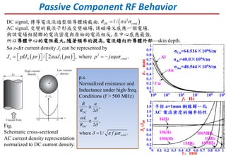
/DC condR l a DC signal, 傳導電流流過整個導體橫截面.
AC signal, 交變的載流子形成交變磁場, 該磁場又感應一個電場,
與該電場相關聯的電流密度與原始的電流相反, 在中心感應最強,
所以導體中心的電阻最大, 隨著頻率的提高, 電流趨向於導體外部—skin depth.
Passive Component RF Behavior
    2
0 1/ 2 , where .z condJ pIJ pr aJ pa p j         
So z-dir current density Jz can be represented by
Fig.
Schematic cross-sectional
AC current density representation
normalized to DC current density.
p.s.
Normalized resistance and
Inductance under high-freq.
Conditions (f > 500 MHz)
,
2
,
2
where 1/ .
DC
DC
cond
R a
R
L a
R
f



  



1
1/
ex
a
Z j L
j C R


 

Ca 為寄生電容(模擬電荷分離)
Cb 為寄生電容(模擬內部引線電容),
L = Lex等效引線電感
知道 Ca, L 就可計算出等效阻抗
Fig. Electric equivalent circuit
representation of the resistor.
Chip R (at high frequency)
b aC C
parasitic capacitance Ca = 5 pF
0 2
ln 1
2
ex
l l
L
a


  
   
  
1. at low freq. the impedance of the resistor is
equal to R.
2. As the freq. > 100 MHz, the effect of the stray
capacitance becomes dominant, which causes
the impedance of the resistor to decrease.
3. Beyond the resonance at 20 GHz, the total
impedance increases due to the lead inductance.
p.s. picture depend on each R case
Chip C (at high frequency)
Fig. Electric equivalent circuit
for a high-frequency capacitor.
Higher freq, dielectric become lossy
(there is a conductor current flow).
1
ex s
e
Z j L R
G j C


  

L 為寄生引線電感
Rs 為寄生引線串聯Ohmic loss
Re 等效介質損耗電阻
(高頻介質有 )loss tangen tant die

  
tan 1/die
e e
A
G C R
d

   
0
2 2
s DC
Cu
fa l
R R
a

 
 
p.s. picture depend on each C case
Chip L (at high frequency)
Fig. Equivalent circuit of the
high-frequency inductor.
( )s sZ j L R C 
s d
s d
R R
C C
 
 
1. The inductor acts as like an ideal inductance at
low freq.
2. The impedance of the inductor increases more
rapidly as the freq. approaches resonance (self-
resonant frequency : SRF).
3. After the freq. passes the SRF , the influence of
the parasitic capacitance Cs becomes dominant.
=> the impedance of the coil decreases.
p.s. picture depend on each L case
Cs 為寄生並聯電容
Inductors for RF circuits
Table. Examples of inductor applications in each circuit block of a mobile phone
高頻電感三大功能
Murata(RF元件大廠)在製造電感時把Chip L依用途分為三類
1. high-frequency(RF) circuits,
2. power supply line inductors (power inductors),
3. inductors for general circuits.
現在我們來談一下手機最常見的inductor for RF circuits.
 Used in the high-frequency band from 10 MHz to several GHz.
 As these products require a high Q value, most have a non-magnetic core structure.
 Mainly used in the high-frequency circuits of mobile communications equipment,
such as mobile phones, wireless LAN, and others.
Properties
 Winding copper wire in a spiral shape around an alumina core.
 Thicker wire than the multilayer and film structures, which provides the following features:
1) Low DC resistance is possible.
2) Extremely high Q value.
3) Large currents can be supported.
 These features make the wire wound structure suitable for matching applications in antenna
and PA circuits that require an extremely high Q factor, and resonance applications in IF circuits.
Inductors for RF circuits 3 different structure (I)
 wire wound structure
Inductors for RF circuits 3 different structure (II)
 multilayer structure
 Layering ceramic materials and coil conductor to create an integrated monolithic-type inductor.
 Smaller size and lower cost compared to the wire wound structure.
 Q factor is lower than wire, but provides good overall balance between the
L value deviation, rated current, size, price, and other characteristics.
 Suitable for various applications such as RF circuit matching, choke, and resonance for mobile
communication equipment.
Inductors for RF circuits 3 different structure (III)
 film structure
 Also a multilayer structure, but the coil is formed with high accuracy over ceramic materials.
 Extremly accurate cores providing the following features:
1) High-performance electrical characteristics can be realized even for compact chips (0402 size).
2) Stable inductance and small inductance value steps are supported.
3) High Q and high SRF.
 Narrow deviation and a high Q factor to support trends toward smaller and more lightweight mobile.
 Wire wound inductors feature a high Q value.
 High Q values are used in the matching circuits because their high Q values give them excellent
attenuation characteristics inside the pass band of the filters.
 Matching applications of antennas for maintaining the Tx and Rx sensitivity of the antennas.
 Low Rdc characteristics (high current levels flow), also employed in choke circuits.
 Micromachining of the coil is enabled by forming the electrodes using a photolithography technique.
 Smaller sizes and high Q characteristics mainstream 0603 and 0402 size.
 Used in the matching and resonance circuits of RF units that require miniaturized sizes, minimal
deviation in inductance and finely graded inductance levels.
 Also used in choke circuits that demand miniaturized sizes and low Rdc.
 Multilayer inductors have the lowest Q value of the three structures.
 They feature a good overall balance in terms of the inductance value line-up, size and cost, and are
used in the matching and resonance circuits of RF units and in all kinds of choke circuits.
Inductors for RF circuits Applications (I)
Inductors for RF circuits Applications (II)
Cross-sectional view of a typical chip resistor
Actual construction of a surface-mounted ceramic
multilayer capacitor
1. WCDMA在Uplink採BPSK, Downlink採QPSK
Pulse shaping採RRC(Root-Raised-Cosine)
就是為了防止無線傳輸信號所產生的ISI (Inter Symbol Interference)
那引起ISI最主要原因就是Group Delay
簡單講就是訊號沒有同步造成Group Delay過大引起ISI
2. 為了消除ISI, 引入Pulse shaping技術
主要目的就是消除雜訊,方便解調
而WCDMA所採用的就是RRC Filter
RRC Filter的時域圖就是著名的Broadcom logo
在數學上,就是一個 sinc function
3. LTE在Uplink採SC-FDMA, Downlink採OFDMA
OFDM會更有效率的使用頻寬,並且容納更多人
而他的每一個sub-carrier就是Broadcom logo並且
互相正交叫Multiple OFDM.
近期大事回顧
FFT
RF Block Diagram

Weitere ähnliche Inhalte

Was ist angesagt?

Receiver sensitivity Design Trade-Offs
Receiver sensitivity Design Trade-OffsReceiver sensitivity Design Trade-Offs
Receiver sensitivity Design Trade-OffsHamidKiabi
 
IIP2 requirements in 4G LTE Handset Receivers
IIP2 requirements in 4G LTE Handset ReceiversIIP2 requirements in 4G LTE Handset Receivers
IIP2 requirements in 4G LTE Handset Receiverscriterion123
 
Filtering Requirements for FDD + TDD CA Scenarios
Filtering Requirements for FDD + TDD CA ScenariosFiltering Requirements for FDD + TDD CA Scenarios
Filtering Requirements for FDD + TDD CA ScenariosPei-Che Chang
 
Receiver Desense Common Issue
Receiver Desense Common IssueReceiver Desense Common Issue
Receiver Desense Common Issuecriterion123
 
Challenges In Designing 5 GHz 802.11 ac WIFI Power Amplifiers
Challenges In Designing 5 GHz 802.11 ac WIFI Power AmplifiersChallenges In Designing 5 GHz 802.11 ac WIFI Power Amplifiers
Challenges In Designing 5 GHz 802.11 ac WIFI Power Amplifierscriterion123
 
Performance requirement and lessons learnt of LTE terminal---transmitter part
Performance requirement and lessons learnt of LTE terminal---transmitter partPerformance requirement and lessons learnt of LTE terminal---transmitter part
Performance requirement and lessons learnt of LTE terminal---transmitter partcriterion123
 
802.11ac WIFI Fundamentals
802.11ac WIFI Fundamentals802.11ac WIFI Fundamentals
802.11ac WIFI Fundamentalscriterion123
 
GNSS De-sense By IMT and PCS DA Output
GNSS De-sense By IMT and PCS DA OutputGNSS De-sense By IMT and PCS DA Output
GNSS De-sense By IMT and PCS DA Outputcriterion123
 
RF Matching Guidelines for WIFI
RF Matching Guidelines for WIFIRF Matching Guidelines for WIFI
RF Matching Guidelines for WIFIcriterion123
 
ABCs of Carrier Aggregation
ABCs of Carrier Aggregation ABCs of Carrier Aggregation
ABCs of Carrier Aggregation criterion123
 
EVM Degradation in LTE systems by RF Filtering
EVM Degradation in LTE systems by RF Filtering EVM Degradation in LTE systems by RF Filtering
EVM Degradation in LTE systems by RF Filtering criterion123
 
WIFI Spectrum Emission Mask Issue
WIFI Spectrum Emission Mask IssueWIFI Spectrum Emission Mask Issue
WIFI Spectrum Emission Mask Issuecriterion123
 
Carrier Aggregation Discussion
Carrier Aggregation DiscussionCarrier Aggregation Discussion
Carrier Aggregation Discussioncriterion123
 
RF Issue Due To PA Timing
RF Issue Due To PA TimingRF Issue Due To PA Timing
RF Issue Due To PA Timingcriterion123
 
Analysis of GSM ORFS Issue
Analysis of GSM ORFS IssueAnalysis of GSM ORFS Issue
Analysis of GSM ORFS Issuecriterion123
 
LTE carrier aggregation technology development and deployment worldwide
LTE carrier aggregation technology development and deployment worldwideLTE carrier aggregation technology development and deployment worldwide
LTE carrier aggregation technology development and deployment worldwidecriterion123
 
Relationships Among EVM, BER and SNR + WiFi minimum SNR consideration
Relationships Among EVM, BER and SNR + WiFi minimum SNR considerationRelationships Among EVM, BER and SNR + WiFi minimum SNR consideration
Relationships Among EVM, BER and SNR + WiFi minimum SNR considerationPei-Che Chang
 

Was ist angesagt? (20)

Diplexer duplexer
Diplexer duplexerDiplexer duplexer
Diplexer duplexer
 
Receiver sensitivity Design Trade-Offs
Receiver sensitivity Design Trade-OffsReceiver sensitivity Design Trade-Offs
Receiver sensitivity Design Trade-Offs
 
IIP2 requirements in 4G LTE Handset Receivers
IIP2 requirements in 4G LTE Handset ReceiversIIP2 requirements in 4G LTE Handset Receivers
IIP2 requirements in 4G LTE Handset Receivers
 
Filtering Requirements for FDD + TDD CA Scenarios
Filtering Requirements for FDD + TDD CA ScenariosFiltering Requirements for FDD + TDD CA Scenarios
Filtering Requirements for FDD + TDD CA Scenarios
 
Receiver Desense Common Issue
Receiver Desense Common IssueReceiver Desense Common Issue
Receiver Desense Common Issue
 
DDR Desense Issue
DDR Desense IssueDDR Desense Issue
DDR Desense Issue
 
Challenges In Designing 5 GHz 802.11 ac WIFI Power Amplifiers
Challenges In Designing 5 GHz 802.11 ac WIFI Power AmplifiersChallenges In Designing 5 GHz 802.11 ac WIFI Power Amplifiers
Challenges In Designing 5 GHz 802.11 ac WIFI Power Amplifiers
 
Performance requirement and lessons learnt of LTE terminal---transmitter part
Performance requirement and lessons learnt of LTE terminal---transmitter partPerformance requirement and lessons learnt of LTE terminal---transmitter part
Performance requirement and lessons learnt of LTE terminal---transmitter part
 
802.11ac WIFI Fundamentals
802.11ac WIFI Fundamentals802.11ac WIFI Fundamentals
802.11ac WIFI Fundamentals
 
GNSS De-sense By IMT and PCS DA Output
GNSS De-sense By IMT and PCS DA OutputGNSS De-sense By IMT and PCS DA Output
GNSS De-sense By IMT and PCS DA Output
 
RF Matching Guidelines for WIFI
RF Matching Guidelines for WIFIRF Matching Guidelines for WIFI
RF Matching Guidelines for WIFI
 
ABCs of Carrier Aggregation
ABCs of Carrier Aggregation ABCs of Carrier Aggregation
ABCs of Carrier Aggregation
 
B2 desence
B2 desenceB2 desence
B2 desence
 
EVM Degradation in LTE systems by RF Filtering
EVM Degradation in LTE systems by RF Filtering EVM Degradation in LTE systems by RF Filtering
EVM Degradation in LTE systems by RF Filtering
 
WIFI Spectrum Emission Mask Issue
WIFI Spectrum Emission Mask IssueWIFI Spectrum Emission Mask Issue
WIFI Spectrum Emission Mask Issue
 
Carrier Aggregation Discussion
Carrier Aggregation DiscussionCarrier Aggregation Discussion
Carrier Aggregation Discussion
 
RF Issue Due To PA Timing
RF Issue Due To PA TimingRF Issue Due To PA Timing
RF Issue Due To PA Timing
 
Analysis of GSM ORFS Issue
Analysis of GSM ORFS IssueAnalysis of GSM ORFS Issue
Analysis of GSM ORFS Issue
 
LTE carrier aggregation technology development and deployment worldwide
LTE carrier aggregation technology development and deployment worldwideLTE carrier aggregation technology development and deployment worldwide
LTE carrier aggregation technology development and deployment worldwide
 
Relationships Among EVM, BER and SNR + WiFi minimum SNR consideration
Relationships Among EVM, BER and SNR + WiFi minimum SNR considerationRelationships Among EVM, BER and SNR + WiFi minimum SNR consideration
Relationships Among EVM, BER and SNR + WiFi minimum SNR consideration
 

Andere mochten auch

Differential stripline impedance calculate
Differential stripline impedance calculateDifferential stripline impedance calculate
Differential stripline impedance calculatePei-Che Chang
 
CDMA Zero-IF Receiver Consideration
CDMA  Zero-IF Receiver ConsiderationCDMA  Zero-IF Receiver Consideration
CDMA Zero-IF Receiver Considerationcriterion123
 
Fast fading, Slow fading and Multipath effect in wireless communications
Fast fading, Slow fading and Multipath effect in wireless communicationsFast fading, Slow fading and Multipath effect in wireless communications
Fast fading, Slow fading and Multipath effect in wireless communicationsPei-Che Chang
 
Introduction to differential signal -For RF and EMC engineer
Introduction to differential signal -For RF and EMC engineerIntroduction to differential signal -For RF and EMC engineer
Introduction to differential signal -For RF and EMC engineercriterion123
 
4G wireless
4G wireless4G wireless
4G wirelessPavan K
 
Jaringan Komputer (4G LTE)
Jaringan Komputer (4G LTE)Jaringan Komputer (4G LTE)
Jaringan Komputer (4G LTE)zaenal mustofa
 
Introduction to PAMiD
Introduction to PAMiDIntroduction to PAMiD
Introduction to PAMiDcriterion123
 
PA Output Notch Filter Consideration
PA Output Notch Filter ConsiderationPA Output Notch Filter Consideration
PA Output Notch Filter Considerationcriterion123
 
How to solve ACLR issue
How to solve ACLR issueHow to solve ACLR issue
How to solve ACLR issuecriterion123
 
Tim day cto presentation - lc
Tim day   cto presentation - lcTim day   cto presentation - lc
Tim day cto presentation - lcTIM RI
 
C5 correlation function and power spectrum density of a signal
C5 correlation function and power spectrum density of a signalC5 correlation function and power spectrum density of a signal
C5 correlation function and power spectrum density of a signalPei-Che Chang
 
LTE ADVANCED PPT
LTE ADVANCED PPTLTE ADVANCED PPT
LTE ADVANCED PPTTrinath
 
The 4G LTE Auction in Thailand
The 4G LTE Auction in ThailandThe 4G LTE Auction in Thailand
The 4G LTE Auction in ThailandYOZZO
 
Voice in 4G: CSFB, VoIP & VoLTE
Voice in 4G: CSFB, VoIP & VoLTEVoice in 4G: CSFB, VoIP & VoLTE
Voice in 4G: CSFB, VoIP & VoLTE3G4G
 
Tele rf basic of drive test
Tele rf basic of drive test Tele rf basic of drive test
Tele rf basic of drive test MohaSyed
 
Lte(long term evolution) 4G LTE
Lte(long term evolution) 4G LTELte(long term evolution) 4G LTE
Lte(long term evolution) 4G LTEkaishik gundu
 

Andere mochten auch (20)

Differential stripline impedance calculate
Differential stripline impedance calculateDifferential stripline impedance calculate
Differential stripline impedance calculate
 
CDMA Zero-IF Receiver Consideration
CDMA  Zero-IF Receiver ConsiderationCDMA  Zero-IF Receiver Consideration
CDMA Zero-IF Receiver Consideration
 
Fast fading, Slow fading and Multipath effect in wireless communications
Fast fading, Slow fading and Multipath effect in wireless communicationsFast fading, Slow fading and Multipath effect in wireless communications
Fast fading, Slow fading and Multipath effect in wireless communications
 
NF vs QTINF
NF vs QTINFNF vs QTINF
NF vs QTINF
 
Introduction to differential signal -For RF and EMC engineer
Introduction to differential signal -For RF and EMC engineerIntroduction to differential signal -For RF and EMC engineer
Introduction to differential signal -For RF and EMC engineer
 
4G wireless
4G wireless4G wireless
4G wireless
 
Jaringan Komputer (4G LTE)
Jaringan Komputer (4G LTE)Jaringan Komputer (4G LTE)
Jaringan Komputer (4G LTE)
 
Nonlinearity
NonlinearityNonlinearity
Nonlinearity
 
Introduction to PAMiD
Introduction to PAMiDIntroduction to PAMiD
Introduction to PAMiD
 
Lte-u note
Lte-u noteLte-u note
Lte-u note
 
PA Output Notch Filter Consideration
PA Output Notch Filter ConsiderationPA Output Notch Filter Consideration
PA Output Notch Filter Consideration
 
How to solve ACLR issue
How to solve ACLR issueHow to solve ACLR issue
How to solve ACLR issue
 
Tim day cto presentation - lc
Tim day   cto presentation - lcTim day   cto presentation - lc
Tim day cto presentation - lc
 
4G Backhaul: Accept the challenge
4G Backhaul: Accept the challenge4G Backhaul: Accept the challenge
4G Backhaul: Accept the challenge
 
C5 correlation function and power spectrum density of a signal
C5 correlation function and power spectrum density of a signalC5 correlation function and power spectrum density of a signal
C5 correlation function and power spectrum density of a signal
 
LTE ADVANCED PPT
LTE ADVANCED PPTLTE ADVANCED PPT
LTE ADVANCED PPT
 
The 4G LTE Auction in Thailand
The 4G LTE Auction in ThailandThe 4G LTE Auction in Thailand
The 4G LTE Auction in Thailand
 
Voice in 4G: CSFB, VoIP & VoLTE
Voice in 4G: CSFB, VoIP & VoLTEVoice in 4G: CSFB, VoIP & VoLTE
Voice in 4G: CSFB, VoIP & VoLTE
 
Tele rf basic of drive test
Tele rf basic of drive test Tele rf basic of drive test
Tele rf basic of drive test
 
Lte(long term evolution) 4G LTE
Lte(long term evolution) 4G LTELte(long term evolution) 4G LTE
Lte(long term evolution) 4G LTE
 

Ähnlich wie Passive component z versus freq

Chapter 2 passive components, resonators and impedance matching
Chapter 2 passive components, resonators and impedance matchingChapter 2 passive components, resonators and impedance matching
Chapter 2 passive components, resonators and impedance matchingkiên lý
 
High Performance Printed Circuit Boards - Lecture #3
High Performance Printed Circuit Boards - Lecture #3High Performance Printed Circuit Boards - Lecture #3
High Performance Printed Circuit Boards - Lecture #3Samsung Electro-Mechanics
 
Integrated parasitic elements at high frequencies
Integrated parasitic elements at high frequenciesIntegrated parasitic elements at high frequencies
Integrated parasitic elements at high frequenciesGOPICHAND NAGUBOINA
 
A practical design of lumped, semi lumped & microwave cavity filters
A practical design of lumped, semi lumped & microwave cavity filtersA practical design of lumped, semi lumped & microwave cavity filters
A practical design of lumped, semi lumped & microwave cavity filtersSpringer
 
EC73_-RF_AND_MICROWAVE_ENGINEERING.pdf
EC73_-RF_AND_MICROWAVE_ENGINEERING.pdfEC73_-RF_AND_MICROWAVE_ENGINEERING.pdf
EC73_-RF_AND_MICROWAVE_ENGINEERING.pdfEmmanuelMukubwa2
 
Simple 100 w inverter circuit
Simple 100 w inverter circuitSimple 100 w inverter circuit
Simple 100 w inverter circuitNarasimha Reddy
 
Resistor capacitor inductor
Resistor capacitor inductorResistor capacitor inductor
Resistor capacitor inductorManish Kumar
 
A low power rf id transponder
A low power rf id transponderA low power rf id transponder
A low power rf id transponderBien Morfe
 
The wire
The wireThe wire
The wiresdpable
 
Electric field detector
Electric field detectorElectric field detector
Electric field detectorJawad Ali
 
A LOW POWER, LOW PHASE NOISE CMOS LC OSCILLATOR
A LOW POWER, LOW PHASE NOISE CMOS LC OSCILLATORA LOW POWER, LOW PHASE NOISE CMOS LC OSCILLATOR
A LOW POWER, LOW PHASE NOISE CMOS LC OSCILLATORIJEEE
 
A LOW POWER, LOW PHASE NOISE CMOS LC OSCILLATOR
A LOW POWER, LOW PHASE NOISE CMOS LC OSCILLATORA LOW POWER, LOW PHASE NOISE CMOS LC OSCILLATOR
A LOW POWER, LOW PHASE NOISE CMOS LC OSCILLATORIJEEE
 
Design and Simulation of Low Noise Amplifiers at 180nm and 90nm Technologies
Design and Simulation of Low Noise Amplifiers at 180nm and 90nm TechnologiesDesign and Simulation of Low Noise Amplifiers at 180nm and 90nm Technologies
Design and Simulation of Low Noise Amplifiers at 180nm and 90nm TechnologiesIJERA Editor
 
DESIGN AND ANALAYSIS OF E-SLOT PATCH ANTENNA FORWIMAX LOWER BAND
DESIGN AND ANALAYSIS OF E-SLOT PATCH ANTENNA FORWIMAX LOWER BANDDESIGN AND ANALAYSIS OF E-SLOT PATCH ANTENNA FORWIMAX LOWER BAND
DESIGN AND ANALAYSIS OF E-SLOT PATCH ANTENNA FORWIMAX LOWER BANDIRJET Journal
 
EWB practical workbook
EWB practical  workbookEWB practical  workbook
EWB practical workbookserjani
 

Ähnlich wie Passive component z versus freq (20)

Chapter 2 passive components, resonators and impedance matching
Chapter 2 passive components, resonators and impedance matchingChapter 2 passive components, resonators and impedance matching
Chapter 2 passive components, resonators and impedance matching
 
High Performance Printed Circuit Boards - Lecture #3
High Performance Printed Circuit Boards - Lecture #3High Performance Printed Circuit Boards - Lecture #3
High Performance Printed Circuit Boards - Lecture #3
 
Integrated parasitic elements at high frequencies
Integrated parasitic elements at high frequenciesIntegrated parasitic elements at high frequencies
Integrated parasitic elements at high frequencies
 
A practical design of lumped, semi lumped & microwave cavity filters
A practical design of lumped, semi lumped & microwave cavity filtersA practical design of lumped, semi lumped & microwave cavity filters
A practical design of lumped, semi lumped & microwave cavity filters
 
EC73_-RF_AND_MICROWAVE_ENGINEERING.pdf
EC73_-RF_AND_MICROWAVE_ENGINEERING.pdfEC73_-RF_AND_MICROWAVE_ENGINEERING.pdf
EC73_-RF_AND_MICROWAVE_ENGINEERING.pdf
 
f2001_landinger.ppt
f2001_landinger.pptf2001_landinger.ppt
f2001_landinger.ppt
 
Capacitores
CapacitoresCapacitores
Capacitores
 
Radio frequency mems
Radio frequency memsRadio frequency mems
Radio frequency mems
 
Simple 100 w inverter circuit
Simple 100 w inverter circuitSimple 100 w inverter circuit
Simple 100 w inverter circuit
 
adaindiv1
adaindiv1adaindiv1
adaindiv1
 
Resistor capacitor inductor
Resistor capacitor inductorResistor capacitor inductor
Resistor capacitor inductor
 
A low power rf id transponder
A low power rf id transponderA low power rf id transponder
A low power rf id transponder
 
The wire
The wireThe wire
The wire
 
Electric field detector
Electric field detectorElectric field detector
Electric field detector
 
A LOW POWER, LOW PHASE NOISE CMOS LC OSCILLATOR
A LOW POWER, LOW PHASE NOISE CMOS LC OSCILLATORA LOW POWER, LOW PHASE NOISE CMOS LC OSCILLATOR
A LOW POWER, LOW PHASE NOISE CMOS LC OSCILLATOR
 
A LOW POWER, LOW PHASE NOISE CMOS LC OSCILLATOR
A LOW POWER, LOW PHASE NOISE CMOS LC OSCILLATORA LOW POWER, LOW PHASE NOISE CMOS LC OSCILLATOR
A LOW POWER, LOW PHASE NOISE CMOS LC OSCILLATOR
 
Design and Simulation of Low Noise Amplifiers at 180nm and 90nm Technologies
Design and Simulation of Low Noise Amplifiers at 180nm and 90nm TechnologiesDesign and Simulation of Low Noise Amplifiers at 180nm and 90nm Technologies
Design and Simulation of Low Noise Amplifiers at 180nm and 90nm Technologies
 
DESIGN AND ANALAYSIS OF E-SLOT PATCH ANTENNA FORWIMAX LOWER BAND
DESIGN AND ANALAYSIS OF E-SLOT PATCH ANTENNA FORWIMAX LOWER BANDDESIGN AND ANALAYSIS OF E-SLOT PATCH ANTENNA FORWIMAX LOWER BAND
DESIGN AND ANALAYSIS OF E-SLOT PATCH ANTENNA FORWIMAX LOWER BAND
 
EWB practical workbook
EWB practical  workbookEWB practical  workbook
EWB practical workbook
 
wireless power transfer
wireless power transferwireless power transfer
wireless power transfer
 

Mehr von Pei-Che Chang

Phase Locked Loops (PLL) 1
Phase Locked Loops (PLL) 1Phase Locked Loops (PLL) 1
Phase Locked Loops (PLL) 1Pei-Che Chang
 
NTHU Comm Presentation
NTHU Comm PresentationNTHU Comm Presentation
NTHU Comm PresentationPei-Che Chang
 
Introduction to Compressive Sensing in Wireless Communication
Introduction to Compressive Sensing in Wireless CommunicationIntroduction to Compressive Sensing in Wireless Communication
Introduction to Compressive Sensing in Wireless CommunicationPei-Che Chang
 
Distributed Architecture of Subspace Clustering and Related
Distributed Architecture of Subspace Clustering and RelatedDistributed Architecture of Subspace Clustering and Related
Distributed Architecture of Subspace Clustering and RelatedPei-Che Chang
 
Brief Introduction About Topological Interference Management (TIM)
Brief Introduction About Topological Interference Management (TIM)Brief Introduction About Topological Interference Management (TIM)
Brief Introduction About Topological Interference Management (TIM)Pei-Che Chang
 
Introduction to OFDM
Introduction to OFDMIntroduction to OFDM
Introduction to OFDMPei-Che Chang
 
The Wireless Channel Propagation
The Wireless Channel PropagationThe Wireless Channel Propagation
The Wireless Channel PropagationPei-Che Chang
 
MIMO Channel Capacity
MIMO Channel CapacityMIMO Channel Capacity
MIMO Channel CapacityPei-Che Chang
 
Digital Passband Communication
Digital Passband CommunicationDigital Passband Communication
Digital Passband CommunicationPei-Che Chang
 
Digital Baseband Communication
Digital Baseband CommunicationDigital Baseband Communication
Digital Baseband CommunicationPei-Che Chang
 
The relationship between bandwidth and rise time
The relationship between bandwidth and rise timeThe relationship between bandwidth and rise time
The relationship between bandwidth and rise timePei-Che Chang
 
Millimeter wave 5G antennas for smartphones
Millimeter wave 5G antennas for smartphonesMillimeter wave 5G antennas for smartphones
Millimeter wave 5G antennas for smartphonesPei-Che Chang
 
Introduction of GPS BPSK-R and BOC
Introduction of GPS BPSK-R and BOCIntroduction of GPS BPSK-R and BOC
Introduction of GPS BPSK-R and BOCPei-Che Chang
 

Mehr von Pei-Che Chang (20)

PLL Note
PLL NotePLL Note
PLL Note
 
Phase Locked Loops (PLL) 1
Phase Locked Loops (PLL) 1Phase Locked Loops (PLL) 1
Phase Locked Loops (PLL) 1
 
NTHU Comm Presentation
NTHU Comm PresentationNTHU Comm Presentation
NTHU Comm Presentation
 
Introduction to Compressive Sensing in Wireless Communication
Introduction to Compressive Sensing in Wireless CommunicationIntroduction to Compressive Sensing in Wireless Communication
Introduction to Compressive Sensing in Wireless Communication
 
Distributed Architecture of Subspace Clustering and Related
Distributed Architecture of Subspace Clustering and RelatedDistributed Architecture of Subspace Clustering and Related
Distributed Architecture of Subspace Clustering and Related
 
PMF BPMF and BPTF
PMF BPMF and BPTFPMF BPMF and BPTF
PMF BPMF and BPTF
 
Distributed ADMM
Distributed ADMMDistributed ADMM
Distributed ADMM
 
Brief Introduction About Topological Interference Management (TIM)
Brief Introduction About Topological Interference Management (TIM)Brief Introduction About Topological Interference Management (TIM)
Brief Introduction About Topological Interference Management (TIM)
 
Patch antenna
Patch antennaPatch antenna
Patch antenna
 
Antenna basic
Antenna basicAntenna basic
Antenna basic
 
PAPR Reduction
PAPR ReductionPAPR Reduction
PAPR Reduction
 
Channel Estimation
Channel EstimationChannel Estimation
Channel Estimation
 
Introduction to OFDM
Introduction to OFDMIntroduction to OFDM
Introduction to OFDM
 
The Wireless Channel Propagation
The Wireless Channel PropagationThe Wireless Channel Propagation
The Wireless Channel Propagation
 
MIMO Channel Capacity
MIMO Channel CapacityMIMO Channel Capacity
MIMO Channel Capacity
 
Digital Passband Communication
Digital Passband CommunicationDigital Passband Communication
Digital Passband Communication
 
Digital Baseband Communication
Digital Baseband CommunicationDigital Baseband Communication
Digital Baseband Communication
 
The relationship between bandwidth and rise time
The relationship between bandwidth and rise timeThe relationship between bandwidth and rise time
The relationship between bandwidth and rise time
 
Millimeter wave 5G antennas for smartphones
Millimeter wave 5G antennas for smartphonesMillimeter wave 5G antennas for smartphones
Millimeter wave 5G antennas for smartphones
 
Introduction of GPS BPSK-R and BOC
Introduction of GPS BPSK-R and BOCIntroduction of GPS BPSK-R and BOC
Introduction of GPS BPSK-R and BOC
 

Kürzlich hochgeladen

Input Output Management in Operating System
Input Output Management in Operating SystemInput Output Management in Operating System
Input Output Management in Operating SystemRashmi Bhat
 
Python Programming for basic beginners.pptx
Python Programming for basic beginners.pptxPython Programming for basic beginners.pptx
Python Programming for basic beginners.pptxmohitesoham12
 
Prach: A Feature-Rich Platform Empowering the Autism Community
Prach: A Feature-Rich Platform Empowering the Autism CommunityPrach: A Feature-Rich Platform Empowering the Autism Community
Prach: A Feature-Rich Platform Empowering the Autism Communityprachaibot
 
DEVICE DRIVERS AND INTERRUPTS SERVICE MECHANISM.pdf
DEVICE DRIVERS AND INTERRUPTS  SERVICE MECHANISM.pdfDEVICE DRIVERS AND INTERRUPTS  SERVICE MECHANISM.pdf
DEVICE DRIVERS AND INTERRUPTS SERVICE MECHANISM.pdfAkritiPradhan2
 
KCD Costa Rica 2024 - Nephio para parvulitos
KCD Costa Rica 2024 - Nephio para parvulitosKCD Costa Rica 2024 - Nephio para parvulitos
KCD Costa Rica 2024 - Nephio para parvulitosVictor Morales
 
Gravity concentration_MI20612MI_________
Gravity concentration_MI20612MI_________Gravity concentration_MI20612MI_________
Gravity concentration_MI20612MI_________Romil Mishra
 
Mine Environment II Lab_MI10448MI__________.pptx
Mine Environment II Lab_MI10448MI__________.pptxMine Environment II Lab_MI10448MI__________.pptx
Mine Environment II Lab_MI10448MI__________.pptxRomil Mishra
 
CME 397 - SURFACE ENGINEERING - UNIT 1 FULL NOTES
CME 397 - SURFACE ENGINEERING - UNIT 1 FULL NOTESCME 397 - SURFACE ENGINEERING - UNIT 1 FULL NOTES
CME 397 - SURFACE ENGINEERING - UNIT 1 FULL NOTESkarthi keyan
 
Module-1-(Building Acoustics) Noise Control (Unit-3). pdf
Module-1-(Building Acoustics) Noise Control (Unit-3). pdfModule-1-(Building Acoustics) Noise Control (Unit-3). pdf
Module-1-(Building Acoustics) Noise Control (Unit-3). pdfManish Kumar
 
SOFTWARE ESTIMATION COCOMO AND FP CALCULATION
SOFTWARE ESTIMATION COCOMO AND FP CALCULATIONSOFTWARE ESTIMATION COCOMO AND FP CALCULATION
SOFTWARE ESTIMATION COCOMO AND FP CALCULATIONSneha Padhiar
 
Ch10-Global Supply Chain - Cadena de Suministro.pdf
Ch10-Global Supply Chain - Cadena de Suministro.pdfCh10-Global Supply Chain - Cadena de Suministro.pdf
Ch10-Global Supply Chain - Cadena de Suministro.pdfChristianCDAM
 
TEST CASE GENERATION GENERATION BLOCK BOX APPROACH
TEST CASE GENERATION GENERATION BLOCK BOX APPROACHTEST CASE GENERATION GENERATION BLOCK BOX APPROACH
TEST CASE GENERATION GENERATION BLOCK BOX APPROACHSneha Padhiar
 
Cost estimation approach: FP to COCOMO scenario based question
Cost estimation approach: FP to COCOMO scenario based questionCost estimation approach: FP to COCOMO scenario based question
Cost estimation approach: FP to COCOMO scenario based questionSneha Padhiar
 
2022 AWS DNA Hackathon 장애 대응 솔루션 jarvis.
2022 AWS DNA Hackathon 장애 대응 솔루션 jarvis.2022 AWS DNA Hackathon 장애 대응 솔루션 jarvis.
2022 AWS DNA Hackathon 장애 대응 솔루션 jarvis.elesangwon
 
Earthing details of Electrical Substation
Earthing details of Electrical SubstationEarthing details of Electrical Substation
Earthing details of Electrical Substationstephanwindworld
 
THE SENDAI FRAMEWORK FOR DISASTER RISK REDUCTION
THE SENDAI FRAMEWORK FOR DISASTER RISK REDUCTIONTHE SENDAI FRAMEWORK FOR DISASTER RISK REDUCTION
THE SENDAI FRAMEWORK FOR DISASTER RISK REDUCTIONjhunlian
 
『澳洲文凭』买麦考瑞大学毕业证书成绩单办理澳洲Macquarie文凭学位证书
『澳洲文凭』买麦考瑞大学毕业证书成绩单办理澳洲Macquarie文凭学位证书『澳洲文凭』买麦考瑞大学毕业证书成绩单办理澳洲Macquarie文凭学位证书
『澳洲文凭』买麦考瑞大学毕业证书成绩单办理澳洲Macquarie文凭学位证书rnrncn29
 
Virtual memory management in Operating System
Virtual memory management in Operating SystemVirtual memory management in Operating System
Virtual memory management in Operating SystemRashmi Bhat
 
multiple access in wireless communication
multiple access in wireless communicationmultiple access in wireless communication
multiple access in wireless communicationpanditadesh123
 
TechTAC® CFD Report Summary: A Comparison of Two Types of Tubing Anchor Catchers
TechTAC® CFD Report Summary: A Comparison of Two Types of Tubing Anchor CatchersTechTAC® CFD Report Summary: A Comparison of Two Types of Tubing Anchor Catchers
TechTAC® CFD Report Summary: A Comparison of Two Types of Tubing Anchor Catcherssdickerson1
 

Kürzlich hochgeladen (20)

Input Output Management in Operating System
Input Output Management in Operating SystemInput Output Management in Operating System
Input Output Management in Operating System
 
Python Programming for basic beginners.pptx
Python Programming for basic beginners.pptxPython Programming for basic beginners.pptx
Python Programming for basic beginners.pptx
 
Prach: A Feature-Rich Platform Empowering the Autism Community
Prach: A Feature-Rich Platform Empowering the Autism CommunityPrach: A Feature-Rich Platform Empowering the Autism Community
Prach: A Feature-Rich Platform Empowering the Autism Community
 
DEVICE DRIVERS AND INTERRUPTS SERVICE MECHANISM.pdf
DEVICE DRIVERS AND INTERRUPTS  SERVICE MECHANISM.pdfDEVICE DRIVERS AND INTERRUPTS  SERVICE MECHANISM.pdf
DEVICE DRIVERS AND INTERRUPTS SERVICE MECHANISM.pdf
 
KCD Costa Rica 2024 - Nephio para parvulitos
KCD Costa Rica 2024 - Nephio para parvulitosKCD Costa Rica 2024 - Nephio para parvulitos
KCD Costa Rica 2024 - Nephio para parvulitos
 
Gravity concentration_MI20612MI_________
Gravity concentration_MI20612MI_________Gravity concentration_MI20612MI_________
Gravity concentration_MI20612MI_________
 
Mine Environment II Lab_MI10448MI__________.pptx
Mine Environment II Lab_MI10448MI__________.pptxMine Environment II Lab_MI10448MI__________.pptx
Mine Environment II Lab_MI10448MI__________.pptx
 
CME 397 - SURFACE ENGINEERING - UNIT 1 FULL NOTES
CME 397 - SURFACE ENGINEERING - UNIT 1 FULL NOTESCME 397 - SURFACE ENGINEERING - UNIT 1 FULL NOTES
CME 397 - SURFACE ENGINEERING - UNIT 1 FULL NOTES
 
Module-1-(Building Acoustics) Noise Control (Unit-3). pdf
Module-1-(Building Acoustics) Noise Control (Unit-3). pdfModule-1-(Building Acoustics) Noise Control (Unit-3). pdf
Module-1-(Building Acoustics) Noise Control (Unit-3). pdf
 
SOFTWARE ESTIMATION COCOMO AND FP CALCULATION
SOFTWARE ESTIMATION COCOMO AND FP CALCULATIONSOFTWARE ESTIMATION COCOMO AND FP CALCULATION
SOFTWARE ESTIMATION COCOMO AND FP CALCULATION
 
Ch10-Global Supply Chain - Cadena de Suministro.pdf
Ch10-Global Supply Chain - Cadena de Suministro.pdfCh10-Global Supply Chain - Cadena de Suministro.pdf
Ch10-Global Supply Chain - Cadena de Suministro.pdf
 
TEST CASE GENERATION GENERATION BLOCK BOX APPROACH
TEST CASE GENERATION GENERATION BLOCK BOX APPROACHTEST CASE GENERATION GENERATION BLOCK BOX APPROACH
TEST CASE GENERATION GENERATION BLOCK BOX APPROACH
 
Cost estimation approach: FP to COCOMO scenario based question
Cost estimation approach: FP to COCOMO scenario based questionCost estimation approach: FP to COCOMO scenario based question
Cost estimation approach: FP to COCOMO scenario based question
 
2022 AWS DNA Hackathon 장애 대응 솔루션 jarvis.
2022 AWS DNA Hackathon 장애 대응 솔루션 jarvis.2022 AWS DNA Hackathon 장애 대응 솔루션 jarvis.
2022 AWS DNA Hackathon 장애 대응 솔루션 jarvis.
 
Earthing details of Electrical Substation
Earthing details of Electrical SubstationEarthing details of Electrical Substation
Earthing details of Electrical Substation
 
THE SENDAI FRAMEWORK FOR DISASTER RISK REDUCTION
THE SENDAI FRAMEWORK FOR DISASTER RISK REDUCTIONTHE SENDAI FRAMEWORK FOR DISASTER RISK REDUCTION
THE SENDAI FRAMEWORK FOR DISASTER RISK REDUCTION
 
『澳洲文凭』买麦考瑞大学毕业证书成绩单办理澳洲Macquarie文凭学位证书
『澳洲文凭』买麦考瑞大学毕业证书成绩单办理澳洲Macquarie文凭学位证书『澳洲文凭』买麦考瑞大学毕业证书成绩单办理澳洲Macquarie文凭学位证书
『澳洲文凭』买麦考瑞大学毕业证书成绩单办理澳洲Macquarie文凭学位证书
 
Virtual memory management in Operating System
Virtual memory management in Operating SystemVirtual memory management in Operating System
Virtual memory management in Operating System
 
multiple access in wireless communication
multiple access in wireless communicationmultiple access in wireless communication
multiple access in wireless communication
 
TechTAC® CFD Report Summary: A Comparison of Two Types of Tubing Anchor Catchers
TechTAC® CFD Report Summary: A Comparison of Two Types of Tubing Anchor CatchersTechTAC® CFD Report Summary: A Comparison of Two Types of Tubing Anchor Catchers
TechTAC® CFD Report Summary: A Comparison of Two Types of Tubing Anchor Catchers
 

Passive component z versus freq

  • 1.  2 /DC condR l a DC signal, 傳導電流流過整個導體橫截面. AC signal, 交變的載流子形成交變磁場, 該磁場又感應一個電場, 與該電場相關聯的電流密度與原始的電流相反, 在中心感應最強, 所以導體中心的電阻最大, 隨著頻率的提高, 電流趨向於導體外部—skin depth. Passive Component RF Behavior     2 0 1/ 2 , where .z condJ pIJ pr aJ pa p j          So z-dir current density Jz can be represented by Fig. Schematic cross-sectional AC current density representation normalized to DC current density. p.s. Normalized resistance and Inductance under high-freq. Conditions (f > 500 MHz) , 2 , 2 where 1/ . DC DC cond R a R L a R f         
  • 2. 1 1/ ex a Z j L j C R      Ca 為寄生電容(模擬電荷分離) Cb 為寄生電容(模擬內部引線電容), L = Lex等效引線電感 知道 Ca, L 就可計算出等效阻抗 Fig. Electric equivalent circuit representation of the resistor. Chip R (at high frequency) b aC C parasitic capacitance Ca = 5 pF 0 2 ln 1 2 ex l l L a             1. at low freq. the impedance of the resistor is equal to R. 2. As the freq. > 100 MHz, the effect of the stray capacitance becomes dominant, which causes the impedance of the resistor to decrease. 3. Beyond the resonance at 20 GHz, the total impedance increases due to the lead inductance. p.s. picture depend on each R case
  • 3. Chip C (at high frequency) Fig. Electric equivalent circuit for a high-frequency capacitor. Higher freq, dielectric become lossy (there is a conductor current flow). 1 ex s e Z j L R G j C       L 為寄生引線電感 Rs 為寄生引線串聯Ohmic loss Re 等效介質損耗電阻 (高頻介質有 )loss tangen tant die     tan 1/die e e A G C R d      0 2 2 s DC Cu fa l R R a      p.s. picture depend on each C case
  • 4. Chip L (at high frequency) Fig. Equivalent circuit of the high-frequency inductor. ( )s sZ j L R C  s d s d R R C C     1. The inductor acts as like an ideal inductance at low freq. 2. The impedance of the inductor increases more rapidly as the freq. approaches resonance (self- resonant frequency : SRF). 3. After the freq. passes the SRF , the influence of the parasitic capacitance Cs becomes dominant. => the impedance of the coil decreases. p.s. picture depend on each L case Cs 為寄生並聯電容
  • 5. Inductors for RF circuits Table. Examples of inductor applications in each circuit block of a mobile phone 高頻電感三大功能 Murata(RF元件大廠)在製造電感時把Chip L依用途分為三類 1. high-frequency(RF) circuits, 2. power supply line inductors (power inductors), 3. inductors for general circuits. 現在我們來談一下手機最常見的inductor for RF circuits.  Used in the high-frequency band from 10 MHz to several GHz.  As these products require a high Q value, most have a non-magnetic core structure.  Mainly used in the high-frequency circuits of mobile communications equipment, such as mobile phones, wireless LAN, and others. Properties
  • 6.  Winding copper wire in a spiral shape around an alumina core.  Thicker wire than the multilayer and film structures, which provides the following features: 1) Low DC resistance is possible. 2) Extremely high Q value. 3) Large currents can be supported.  These features make the wire wound structure suitable for matching applications in antenna and PA circuits that require an extremely high Q factor, and resonance applications in IF circuits. Inductors for RF circuits 3 different structure (I)  wire wound structure
  • 7. Inductors for RF circuits 3 different structure (II)  multilayer structure  Layering ceramic materials and coil conductor to create an integrated monolithic-type inductor.  Smaller size and lower cost compared to the wire wound structure.  Q factor is lower than wire, but provides good overall balance between the L value deviation, rated current, size, price, and other characteristics.  Suitable for various applications such as RF circuit matching, choke, and resonance for mobile communication equipment.
  • 8. Inductors for RF circuits 3 different structure (III)  film structure  Also a multilayer structure, but the coil is formed with high accuracy over ceramic materials.  Extremly accurate cores providing the following features: 1) High-performance electrical characteristics can be realized even for compact chips (0402 size). 2) Stable inductance and small inductance value steps are supported. 3) High Q and high SRF.  Narrow deviation and a high Q factor to support trends toward smaller and more lightweight mobile.
  • 9.  Wire wound inductors feature a high Q value.  High Q values are used in the matching circuits because their high Q values give them excellent attenuation characteristics inside the pass band of the filters.  Matching applications of antennas for maintaining the Tx and Rx sensitivity of the antennas.  Low Rdc characteristics (high current levels flow), also employed in choke circuits.  Micromachining of the coil is enabled by forming the electrodes using a photolithography technique.  Smaller sizes and high Q characteristics mainstream 0603 and 0402 size.  Used in the matching and resonance circuits of RF units that require miniaturized sizes, minimal deviation in inductance and finely graded inductance levels.  Also used in choke circuits that demand miniaturized sizes and low Rdc.  Multilayer inductors have the lowest Q value of the three structures.  They feature a good overall balance in terms of the inductance value line-up, size and cost, and are used in the matching and resonance circuits of RF units and in all kinds of choke circuits. Inductors for RF circuits Applications (I)
  • 10. Inductors for RF circuits Applications (II)
  • 11. Cross-sectional view of a typical chip resistor Actual construction of a surface-mounted ceramic multilayer capacitor
  • 12. 1. WCDMA在Uplink採BPSK, Downlink採QPSK Pulse shaping採RRC(Root-Raised-Cosine) 就是為了防止無線傳輸信號所產生的ISI (Inter Symbol Interference) 那引起ISI最主要原因就是Group Delay 簡單講就是訊號沒有同步造成Group Delay過大引起ISI 2. 為了消除ISI, 引入Pulse shaping技術 主要目的就是消除雜訊,方便解調 而WCDMA所採用的就是RRC Filter RRC Filter的時域圖就是著名的Broadcom logo 在數學上,就是一個 sinc function 3. LTE在Uplink採SC-FDMA, Downlink採OFDMA OFDM會更有效率的使用頻寬,並且容納更多人 而他的每一個sub-carrier就是Broadcom logo並且 互相正交叫Multiple OFDM. 近期大事回顧 FFT