SlideShare a Scribd company logo
1 of 70
Download to read offline
Frequency Measurement and Switching Instruments
Multitasker T601
Instruction Manual
Version 1.01E
2 Channel Tachometer with digital and analog Input and Output
• T601.50: Part No.: 384Z-05602 (AC Version)
• T601.10: Part No.: 384Z-05603 (DC Version)
JAQUET AG, Thannerstrasse 15, CH-4009 Basel
Tel. +41 61 306 88 22 Fax +41 61 306 88 18 E-Mail: info@jaquet.com
Instruction Manual T601 JAQUET AG
Version 1.01E 2/70
Contents
1 SAFETY NOTICE 6
2 PRODUCT FEATURES 7
3 SPECIFICATIONS 8
3.1 General 8
3.2 Inputs 9
3.2.1 Sensor Inputs 9
3.2.2 Analog Input 11
3.3 Binary Inputs 12
3.4 CAN Input 12
3.5 Outputs 13
3.5.1 Analog Outputs 13
3.5.2 Relays Outputs 14
3.5.3 Open Collector Outputs 14
3.6 Data communication 15
3.6.1 Ethernet 15
3.6.2 Connection to the Display 15
3.7 Environment 15
3.7.1 Climatic Conditions 15
3.7.2 Electromagnetic immunity 15
3.7.3 Other Standards 15
4 PRINCIPLE OF OPERATION 16
4.1 General 16
4.2 Machine factor 18
4.2.1 Measured 18
4.2.2 Calculated 18
4.2.3 Other physical parameters 18
4.3 Datalogger 19
4.3.1 Min- Max value registers 19
4.3.2 Event Recorder 19
4.3.3 Trip Datalogger 19
5 INSTALLATION 21
6 CONNECTIONS 22
6.1 Front view 22
6.1.1 Front view T601 22
6.1.2 Terminal A 23
6.1.3 Terminal B 25
6.2 Top View 27
Instruction Manual T601 JAQUET AG
Version 1.01E 3/70
6.2.1 Terminal C 27
7 CONFIGURATION VIA PC SOFTWARE 28
7.1 Software Concept 28
7.2 PC Settings 28
7.3 Download configuration software 29
7.3.1 Direct execution 29
7.3.2 Save as 29
7.4 Configuration software 29
7.4.1 Configuration user and Process user 29
7.4.2 Log in 30
7.4.3 Main Window, Min-Max Values and System Limit Matrix 30
7.4.4 Logging in and out 31
7.5 Configuration file… 31
7.5.1 … creating new 31
7.5.2 … resetting to factory default 31
7.5.3 … loading 32
7.5.4 … saving 32
7.5.5 … printout 32
7.6 Communication with the Tachometer 33
7.6.1 Read measured data 33
7.6.2 Reading configuration from the T601 33
7.6.3 Writing a configuration to the T601 34
7.6.4 Compare data 34
7.6.5 Read and/or Delete Event Recorder 34
7.7 Configuring 35
7.7.1 Configure Speed Sensors 35
7.7.2 Configure Analog Sensor 36
7.7.3 Configure binary input 37
7.7.4 CAN 38
7.7.5 Set Measurement Interval 38
7.7.6 Sensor Alarm 39
7.7.7 Machine factor 39
7.7.8 Direction Sensing 40
7.7.9 Analog Input Range 40
7.7.10 Dynamic Error 40
7.7.11 Math Function 41
7.7.12 System Limits 42
7.7.13 Relay Outputs 43
7.7.14 Open Collector Outputs 44
7.7.15 Analog Output 45
7.7.16 Copy Parameter Set 46
7.7.17 Change-over delay 47
7.7.18 Data-logger Memory 48
7.8 Settings 48
7.8.1 Ethernet Interface 48
7.8.2 Time and Date settings 49
7.8.3 Changing the Password 49
7.8.4 Displays via Bluetooth® 50
7.8.5 Display Settings 51
7.9 Info 51
Instruction Manual T601 JAQUET AG
Version 1.01E 4/70
8 OPERATING BEHAVIOUR 52
8.1 Power on 52
8.1.1 Analog Output 52
8.1.2 Relay Output 52
8.1.3 Open Collector Output 52
8.2 Frequency Measurement 53
8.2.1 The Adaptive Trigger Level 53
8.2.2 Signal failure 54
8.3 Analog Input 54
8.4 Functions 54
8.4.1 “Exec“ Push button 54
8.4.2 Parameter sets A, B, C and D 54
8.4.3 Limits 54
8.4.4 Window Function 55
8.4.5 Rotational Direction 55
8.4.6 Creep Detection 56
8.4.7 Frequency x2 and x4 56
8.4.8 Relay and Open Collector Latch Function 57
8.4.9 Analog Output 57
8.5 Sensor Error 57
8.5.1 Sensor error 57
8.5.2 System alarm 57
8.6 Power failure 57
8.7 Behaviour during Configuration 57
9 MECHANICAL CONSTRUCTION / HOUSING 58
9.1 Tachometer 58
9.2 Mounting 59
10 ACCESSORIES 60
10.1.1 Interface cable 60
10.2 Display 60
10.2.1 Cable version 60
10.2.2 Bluetooth® Version 60
11 MAINTENANCE / REPAIR 61
12 SOFTWARE-VERSION 61
12.1 Configurations software 61
12.2 Firmware 61
13 WARRANTY 61
APPENDIX 62
Instruction Manual T601 JAQUET AG
Version 1.01E 5/70
A: Declaration of Conformity 62
B: Possible Problems 63
Instruction Manual T601 JAQUET AG
Version 1.01E 6/70
1 Safety notice
Series T601 tachometers should only be connected by trained personnel.
T601 tachometers do not generate dangerous potentials but as soon as circuits
exhibiting dangerous potentials are connected, then these may be present in the
tachometer circuits.
• The Tachometers may only be opened for repair by trained personnel.
• These Instruments correspond to protection class I. The PE terminal must
therefore be earthed.
• The instructions in this manual must be strictly adhered to.
• Not following these instructions could result in damage to equipment or plant and injury to personnel, as
well as negating warranty claims!
• Units that have suffered electrical over load, mechanical stress or been operated outside of specification
must be immediately switched off and returned to the manufacturer for repair.
• These Instruments have been developed and produced in accordance with the IC-Publication 348 and
left our factory in perfect condition.
Instruction Manual T601 JAQUET AG
Version 1.01E 7/70
2 Product features
T601 Series tachometers measure and monitor frequency signals in the range 0.025Hz to 50kHz along with
analog signals.
The following functionality is provided:
• 2 Frequency inputs (Speed sensor)
• 1 Analog input for current or temperature (Pt100)
• 2 Binary input
• 2 Analog outputs
• 4 Relays
• 2 Open Collector outputs
• 4 Parameter sets each having 6 System limits with 4 Limit values
• Creep detection
• Direction detection
• Data logger function
• Sensor monitoring
• System monitoring
T601’s are configured via Computer (PC) and a user program.
Two tachometer models are offered:
• T601.50: Part No. 384Z-05602 (AC Version)
• T601.10: Part No. 384Z-05603 (DC Version)
Instruction Manual T601 JAQUET AG
Version 1.01E 8/70
3 Specifications
Reference temp: + 20 °C
3.1 General
Measurement interval 2 ms / 5 ms / 10 ms / 20 ms / 50 ms / 100 ms / 200 ms / 500 ms / 1 s / 2 s / 5 s
(Under certain circumstances, frequency measurements can take several
measurement intervals)
Supply voltage AC Version 90…264 VAC (47...63 Hz)
DC Version 18…36 VDC
Isolation voltage AC Version 3000 VAC (of the AC/DC power supply)
DC Version 1500 VDC (of the DC/DC converter)
Isolation Galvanic isolation between:
• Supply
• Sensor input incl. sensor supply, analog input, CAN, Display
• Binary input 1
• Binary input 2
• Analog output 1
• Analog output 2
• Relay outputs
• Open Collector output 1
• Open Collector output 2
• Ethernet interface
Power consumption T601 without Display
T601 with D211
(Cable version)
T601 with D201
(BlueTooth® version)
P min.
(W)
P max.
(W)
P min.
(W)
P max.
(W)
P min.
(W)
P max.
(W)
AC Vers.
110 VAC 5.0 11.0 6.8 13.0 5.1 11.2
230 VAC 8.0 15.2 10.0 16.7 8.1 15.4
DC Vers.
18 VDC 3.0 7.5 4.4 8.8 3.2 7.7
24 VDC 3.0 7.4 4.4 8.7 3.2 7.6
36 VDC 3.2 7.5 4.6 8.8 3.4 7.7
Power supply bridging
with P max.
T601 without Display
T601 with D211
(Cable version)
T601 with D201
(BlueTooth® version)
AC Vers.
110 VAC 39 ms 37 ms 31 ms
230 VAC 200 ms 190 ms 170 ms
DC Vers.
18 VDC 7 ms 6.8 ms 5.5 ms
24 VDC 23 ms 22 ms 19 ms
25 VDC 26 ms 25 ms 22 ms
36 VDC 70 ms 67 ms 55 ms
Operating temperature AC Version -25 °C…+50 °C
DC Version -40 °C…+70 °C
Storage temperature AC Version
-40 °C…+85 °C
DC Version
Weight AC Version 450 g
DC Version 400 g
Sealing to DIN
EN 60529
IP 20
Instruction Manual T601 JAQUET AG
Version 1.01E 9/70
3.2 Inputs
3.2.1 Sensor Inputs
Number 2 Sensor inputs
Frequency range (-3 dB) 0.025 Hz … 50 kHz
Measurement range Programmable within the frequency range
Measurement accuracy 0.002 %
Resolution
(Frequency)
10 ns
Input impedance > 11.5 kΩ
(0.1 Hz 80 kΩ, 1 kHz 18.5 kΩ, 10 kHz 16 kΩ, 50 kHz 11.6 kΩ)
Input signal for fixed 3V
trigger (+/-15 %)
• Max. voltage: 80 VRMS (226 Vpp)
• Best suited to digital signals
• Schmitt Trigger Input (Hysteresis > 1 V)
• „0“ = Low Level to 1.25 V
• „1“ = High level from 3 V (+/- 15 %)
• Min. pulse width: 5 µs
• Not DC-decoupled
Input signal for adaptive
trigger min. 57 mVpp
(+/-10 %) 20 mVRMS
• Max. voltage: 80 VRMS (226 Vpp)
• DC-decoupled
• The Trigger level automatically adapts itself to the input signal in the range
+28.5 mV to +2 V. The Adaptive Trigger improves the signal to noise immunity
e.g. where electromagnetic sensors are used.
Min. Trigger level: 57 mVpp +/-10% = 20 mVRMS +/-10% U min. = f(Frequency)
0.01
0.10
1.00
10.00
100.00
1000.00
0.01
0.1
1
10
100
1000
10000
100000
Frequency (Hz)
SensorSignal(Vpp)
O.K
NOT O.K.
Instruction Manual T601 JAQUET AG
Version 1.01E 10/70
Input signal for adaptive
trigger min. 500 mVpp
(+/-10 %) 180 mVRMS
• Max. voltage: 80 VRMS (226 Vpp)
• DC-decoupled
• The Trigger level automatically adapts itself to the input signal in the range
+250 mV to +2 V. The Adaptive Trigger improves the signal to noise immunity
e.g. where electromagnetic sensors are used.
Min. Trigger level: 500 mVpp +/-10% = 180 mVRMS +/-10% U min. = f(Frequency)
0.1
1.0
10.0
100.0
1000.0
0.01
0.1
1
10
100
1000
10000
100000
Frequency (Hz)
SensorSignal(Vpp)
O.K.
NOT O.K.
Sensor supply • +14 V +/- 0.5 V, max. 35 mA / Short circuit proof
• If the current limit has been activated, then the circuit needs to be disconnected
to reset the protection.
Typical voltage curve as a function of sensor current
Sensor voltage = f (Sensor current)
13.6
13.8
14.0
14.2
14.4
14.6
14.8
0 5 10 15 20 25 30 35 40 45
Sensor current (mA)
Sensorvoltage(V)
Integral pull up resistor 1000 Ω to +14 V (Only for 2 wire active e.g. NAMUR sensors)
Screen Terminals are provided for each sensor cable screen (Sh1 and Sh2). These
terminals are internally connected to the ground of the sensor input.
Instruction Manual T601 JAQUET AG
Version 1.01E 11/70
Sensor monitoring 3 sensor monitoring settings are available in the configuration software:
• No Sensor Monitoring
• Monitoring of supplied sensors (active Sensor Types)
[Also for 2 wire sensors that are supplied via the internal Pull-up resistor (1 kΩ)
Sensors drawing current outside of Imin or Imax are considered to be faulty.
Imin = 0.5…35 mA
Imax = 0.5…35 mA
• Monitoring of non powered sensors (passive Sensor Types)
[For 2 wire sensors such as electromagnetic sensors.]
The sensor is considered to be faulty if the line is broken.
Here the sensor impedance is dynamically measured.
Z < 60 kΩ = OK
Z > 125 kΩ = NOT OK
3.2.2 Analog Input
Number One 0/4 ..20 mA or 1 Temperature input (Pt100)
3.2.2.1 Analog Input as Current Input
Resolution 12 Bit (4096 Steps)
Max Linearity error 1 LSB (Least Significant Bit) ca. 5.37 uA
Measurement error Max. 0.25 % of Measured value + 1 LSB (-25 °C +50 °C)
Max. 0.50 % of Measured value + 1 LSB (-40 °C +70 °C)
Accuracy class 0.2 % of final value
Open circuit voltage Max. 13.7 VDC (active Sensor input)
Driving voltage Min. 12 VDC (active Sensor input)
External load Max. 600 Ω (active Sensor input)
Internal current limit IMax = 24 mA+/-1 mA (active Sensor input)
Measurement
Impedance
50 Ω (passive Sensor input)
Damping Hardware time constant T = 4.1 ms
10 % 90 % = 8.6 ms (Hardware)
Actual time = Hardware time constant + Max. 1 Measurement interval
Temperature Drift Typ.: 100 ppm/K, max. 150 ppm/K
3.2.2.2 Analogue Input as Temperature Input
Measurement 2 wire or 3 wire
Sensor Pt100 (Measurement current = 950 uA)
Measuring range -50 °C +300 °C
Accuracy +/-0.5 °C of the measurement value
Max. cable resistance 28 Ω (3 Wire Measurement)
Max. cable length, 3
wire measurement
Cable resistance
AWG Diameter
Cross
section Resistance Max. Length
mm mm
2
Ω/km Pt100 T601
38 0.1 0.0082 2190 12.8 m
36 0.13 0.0127 1300 21.5 m
34 0.16 0.02 844 33.2 m
32 0.2 0.032 547 51.2 m
30 0.25 0.051 351 79.8 m
28 0.32 0.08 232 120.7 m
25 0.46 0.16 108 259.3 m
24 0.51 0.21 87.5 320.0 m
2 wire connection The cable must be kept as short as possible, since the cable resistance will be
measured as well; e.g. a cable having 1 Ω (2 x 0.5 Ω wires) would introduce an
error of about 2.5 °C.
Instruction Manual T601 JAQUET AG
Version 1.01E 12/70
Damping Hardware time constant T = 10 ms
10 % 90 % = 21 ms (Hardware)
Actual time = Hardware time constant + Max. 1 Measurement interval
3.3 Binary Inputs
Number 2 Active Binary Inputs and 1 push button (EXEC – logic OR with Binary input B1).
Level Logic 0 = 0 V….+5 V
Logic 1 = +15 V….+36 V
Isolation voltage 1500 VRMS
Input resistance Rmin = 8.2 kΩ
3.4 CAN Input
All T600 digital inputs and outputs are represented in the Device Profile DS-404. In addition, 3 manufacturers
binary inputs that influence the T600 process are defined in a specific profile area.
Instruction Manual T601 JAQUET AG
Version 1.01E 13/70
3.5 Outputs
3.5.1 Analog Outputs
Number 2 Analog outputs
Isolation voltage 1000 VDC
Output type Current (selectable 0…20 mA / 4…20 mA)
Load Max. 500 Ω
Open circuit voltage Max. 15 V
Typical error curve
-1
-0.9
-0.8
-0.7
-0.6
-0.5
-0.4
-0.3
-0.2
-0.1
0
0.1
0.2
0.3
0.4
0.5
0.6
0.7
0.8
0.9
1
0.00E+00
1.00E-03
2.00E-03
3.00E-03
4.00E-03
5.00E-03
6.00E-03
7.00E-03
8.00E-03
9.00E-03
1.00E-02
1.10E-02
1.20E-02
1.30E-02
1.40E-02
1.50E-02
1.60E-02
1.70E-02
1.80E-02
1.90E-02
2.00E-02
I (A)
Measurementerror(%)
0.2 % (from measured value) + 2 LSB
CLASS 0.1 % (from End Value)
Mode
20.5
20
12
4
0
Mode
Output value
0...20mA
4...20mA
Start value End value
[mA]
21
2
Error level
4 … 20mA
Error level
0 … 20mA
Transfer Functions Start value < or > End value
Outputvalue
Output
Startvalue < Endvalue
Output
Startvalue > Endvalue
Outputvalue
Resolution 14 Bit (16384 increments)
Max. Linearity error 2 LSB (Least Significant Bit) approx. 2.7 uA
Measuring error Max. 0.15 % f.m.v. + 2 LSB (-25 °C +50 °C)
Max. 0.20 % f.m.v. + 2 LSB (-40 °C +70 °C)
Instruction Manual T601 JAQUET AG
Version 1.01E 14/70
Accuracy class 0.1 % of the end value
Damping Hardware time constant T = 4.1 ms
10 % 90 % = 8.6 ms (Hardware)
Actual time = Hardware time constant + Software setting (configuration)
Temperature Drift Typ.: 50 ppm/K, max. 120 ppm/K
3.5.2 Relays Outputs
Number 4 Relay output
Type Mono-stable single change-over
Functions • May be assigned to System Limit 1..6, Sensor Alarm, Static error Sensor 1 or
2, dynamic error, Static error Analog input, always on or off.
• With or without Hold function (Reset via Binary input)
• Fail Safe or Not Fail Safe
Max. switching current
Reaction time Effective Measurement interval + max 6 ms
Contact resistance 50 mΩ Max. (Initial-contact)
Contact isolation 1500 VAC (coil to contact)
1000 VAC (between open contacts)
3.5.3 Open Collector Outputs
Number 2 Open Collector output
Type Opto-coupler (passive)
External resistance IC nominal = 15 mA (RPull-up = V / I) Example: V = 24 V R = 1.6 kΩ
IC max. = 30 mA
Reaction time • As Frequency output: <30 us
• Effective Measurement interval + max 30 us
Load voltage V = 5 VDC…36 VDC
Isolation voltage 1500 VAC
Functions • May be assigned to System Limit 1..6, Sensor Alarm, static error Sensor 1 or 2,
dynamic error, static error Analog input, always ON or OFF, Frequency S1 or
2, Frequency x 2, Frequency x 4.
• With or without hold function (Reset via Binary input)
• Fail Safe or Not Fail Safe
Inverting Open collector output frequencies are in phase with the input signal.
Instruction Manual T601 JAQUET AG
Version 1.01E 15/70
3.6 Data communication
3.6.1 Ethernet
Number 1 Ethernet interface
Physical Layer Ethernet 10Base-T, IEEE 802.3i
Max cable length 100 m
Transmission rate 10 MBit/s
Connection Front panel, 8P8C (RJ45)
Usage Configuration and measurement status
Protocol Peer to Peer
Connecting cable Use a crossover cable
3.6.2 Connection to the Display
Number 1
Connector Plug (5 pins)
Usage Connection to the Display
3.6.2.1 Cable
Cable Complete 6m long cable to connect a display. See Chapter 10.2.1 Cable version
3.6.2.2 Bluetooth®
Max. distance to the
Display
10 m – 150 m
Class Bluetooth® Class 1 + 7 dBm
3.7 Environment
3.7.1 Climatic Conditions
Standard DIN 40 040
Operating temperature See 3.1 General
Storage temperature See 3.1 General
Relative humidity • 75 % average over 1 year; to 90 % for max. 30 days
• Condensation to be avoided
3.7.2 Electromagnetic immunity
Electrostatic discharge EN 61000-4-2 Contact 6 kV, air 8 kV
Electromagnetic fields EN 61000-4-3 30 V/m, not modulated and AM 80 % with 1000Hz Sinus
wave
Fast transients EN 61000-4-4 2 kV, repeated 5 kHz duration 15 ms period 300 ms
Slow transients EN 61000-4-5 Line / line +/- 1kV, earth line +/- 2kV, 1 per minute
Conducted HF EN 61000-4-6 3 V eff (180 dBuV) 10 kHz – 80 MHz
Mains frequency
Magnetic field
EN 61000-4-8 50 Hz, 100 A/m 2 minutes
Voltage dips EN 61000-4-11 Voltage dips, short interruptions and voltage variations
immunity tests
3.7.3 Other Standards
Communauté Européenne
Instruction Manual T601 JAQUET AG
Version 1.01E 16/70
4 Principle of Operation
4.1 General
T601’s are microprocessor controlled and operate on the period measurement principle whereby the input
signal period is measured during the measurement interval. The frequency is determined from the reciprocal
of the average input period. The relationship between frequency and speed is determined by the machine
factor.
The status of System Limits can be affected by various inputs. Inputs to System Limits may be logically
combined AND or OR. System limit inputs may be: speed inputs, analog input, a math function of the 2 speed
values or the analog input, both binary inputs, creep, direction, CAN interface.
A hysteresis may be set in the case of both speed inputs, the analog input and the math function.
The 6 System Limits may be variously defined in 4 parameter sets that may be selected via binary inputs.
The 4 relays and 2 open collectors may be assigned to react to the System Limits. The 2 open collectors may
alternatively be used to output the input frequency (f), frequency x2, frequency x4.
In the case of limits, the relay and open collector status may be latched and then reset via binary input.
The system permanently monitors itself. Sensors may in addition be monitored. Sensor alarm may be used in
the configuration to influence System Limits. System error would influence the relays, open collectors and
analog outputs and the front panel LED would go out.
Frequency outputs (Open Collector Outputs) are not influenced by the machine factor but where so defined
correspond to the input signal. For frequency x2 or x4 the 2 input signals should ideally be phase shifted by 90
degrees.
Parameter input is via resident PC software and the Ethernet interface. This may also be used to interrogate
the unit and display measurement and unit status.
The parameters are safely stored in EEPROM.
Instruction Manual T601 JAQUET AG
Version 1.01E 17/70
Instruction Manual T601 JAQUET AG
Version 1.01E 18/70
4.2 Machine factor
The Machine factor determines the relationship between the measured sensor frequency and the
corresponding speed.
There are two means of determining this value:
4.2.1 Measured
Where the Frequency (f) at the Sensor input and the corresponding speed (n) is known:
4.2.2 Calculated
The relationship between sensor signal frequency (f) and speed (n) at a pole wheel is:
Machine factor is then:
Should a gearbox be present between the pole wheel and drive shaft the formula becomes:
The gearbox ratio is determined as follows:
4.2.3 Other physical parameters
In principle any parameter may be processed as long as it can be translated into a frequency proportional
value. The formulas above may still be applied whereby the required parameter is used in place of speed.
n
f
M =
M = Machine factor
f = Signal frequency at machine speed n
n = Machine speed
n
f
M =
M = Machine factor
f = Signal frequency at known speed
n = Machine speed at measured signal frequency
f = Signal frequency in Hz
n = Pole wheel speed in U/min (rpm)
p = Number of teeth60
pn
f
×
=
60
ip
M
×
=
M = Machine factor
p = Number of teeth
i = Gearbox ratio
1
2
2
1
p
p
n
n
i ==
i = Gearbox ratio
n1 = Primary pole wheel speed (Sensor position)
n2 = Secondary pole wheel speed (Speed to be indicated)
p1 = Nr. of teeth – primary pole wheel
p2 = Nr. of teeth – secondary pole wheel
60
p
M =
M = Machine factor
p = Number of teeth
Instruction Manual T601 JAQUET AG
Version 1.01E 19/70
4.3 Datalogger
This function is for the Firmware version 0.88 not available.
4.3.1 Min- Max value registers
The minimum and maximum values of input signals S1 and S2 along with the analog value are measured and
stored. The Min / Max registers may be reset via appropriately configured binary inputs (see 7.7.3) or via the
configuration software (see 7.6.5 Event Recorder readout and / or reset).
NB. If the Min / Max registers are reset via the configuration software, then the event and trip data recorders
are reset as well!
4.3.2 Event Recorder
The event recorder logs events such as when a relay operates or a system limit occurs. The following events
are logged:
• Relay 1 – 4
• Open Collector 1 and 2 (If assigned to a System Limit)
• Binary input 1 and 2
• CAN Cell
• Sensor alarm
• System Limit 1 – 6 from the active parameter set
• Creep
• Direction
• Sensor fault (Static Fault S1, Static Fault S2, Dynamic Fault, Static Fault Analog Input)
146 events can be recorded for each item in the list. Each event is time and date stamped. Every event has its
own memory range. The event memory can be defined as Ring or Limited Memory. (see 7.7.18 Data-logger
Memory)
Time and date are only used for the event recorder and have no influence over other tachometer functions.
In the event of power loss the clock will continue to operate for approx. 7 days. Thereafter it must be reset.
(see 7.8.2 Time and Date settings)
NB: If the memory is reset via the configuration software, then the event recorder, trip data logger and min /
max registers are reset at the same time!
4.3.3 Trip Datalogger
A Trip Data Logger is assigned to System Limit 1 in each parameter set. When activated by a System Limit 1
becoming active, 100 additional parameters before and after the trip event are logged. The additional
parameters being:
• Speed - Sensor S1
• Speed - Sensor S2
• Analog input value
• Status – Binary input 1
• Status – Binary input 2
• CAN Cell status
• Sensor alarm
• Creep
• Direction
This function stores data for a fixed event window and needs to be reset via binary input to allow recording of
further trip event data.
Instruction Manual T601 JAQUET AG
Version 1.01E 20/70
NB: If the memory is deleted via configuration software then the safety and event recorders along with the min
/ max registers are reset at the same time!
Instruction Manual T601 JAQUET AG
Version 1.01E 21/70
5 Installation
Series T601 tachometers may only be installed by competent personnel. Only undamaged and correctly
configured units may be used. Please note the safety instructions in chapter 1 Safety notice.
They should be connected to the power supply by means of an isolating switch and correspond to protection
class I. The PE terminal must therefore be earthed.
Before switching on check that the supply is within the permissible range.
The sensor cable screens must be connected to the terminals „Sh1“ and „Sh2“ respectively so as to minimize
the effects of signal noise. These terminals are internally connected to 0V (not PE).
Attention: If the password has been changed, there is no way of returning to a factory setup. If the password
is forgotten, you have to send in the tachometer and the Jaquet-Service-Team will set it back.
Instruction Manual T601 JAQUET AG
Version 1.01E 22/70
6 Connections
6.1 Front view
6.1.1 Front view T601
The Ethernet and CAN interfaces along with the control LED and execute push button (EXEC) are all located
at the front. A crossover Ethernet cable is required for configuration (see Chapter 7)
Terminal B
Terminal A
Instruction Manual T601 JAQUET AG
Version 1.01E 23/70
6.1.2 Terminal A
Supply
N (-) : Neutral (Return)
P (+) : Live
PE : Earth
Binary inputs
B1+ : positive B1
B1- : negative B1
B2+ : positive B2
B2- : negative B2
Sensor connections S1 / S2
S1 : Sensor input S1
Sh1 : Screen S1
V1+ : Sensor Supply S1
V1- : 0V S1
S2 : Sensor input S2
Sh2 : Screen S2
V2+ : Sensor Supply S2
V2- : 0V S2
Analog outputs
I1+ : positive I1
I1- : negative I1
I2+ : positive I2
I2- : negative I2
Sh2 V2
-
I2
-
I2
+
Sh1 V1
-
S1 V1
+
I1
-
I1
+
B2
-
B2
+
B1
-
B1
+
PEP
+
N
-
S2 V2
+
+
-
Binary input
Current output
Power supply
+
-
+-+-
I1 I2
B2B1
Sensor 1 Sensor 2
For connection recommendation see
below
Instruction Manual T601 JAQUET AG
Version 1.01E 24/70
Ferostatic sensors (2-wire)
(DSF..., NAMUR)
Sensors with NPN- output (open collector)
(DSF..., DSD...)
Electromagnetic 2-wire sensors
(DSE..., Green Line E...)
Sensors with amplifier and fixed trigger level at 1.25/3V (DC)
(DSF..., DSD..., Greenline F..., D..., Y... )
or
Sensor types
or
Configuration recommendation of the software parameters
Connection recommendation
Terminal for Sensor 1
Sh2 V2
-
V1
+
S2 V2
+
Sh2I2
+
Sh1 V1
-
S1 V1
+
+V
S
-
+
-
+
-
MDR
+V
S
-
Terminal for Sensor 2
Instruction Manual T601 JAQUET AG
Version 1.01E 25/70
6.1.3 Terminal B
Open Collector outputs Oc1 / Oc2
Oc1+ : positive Open Collector 1 (Emitter)
Oc1- : negative Open Collector 1 (Collector)
Oc2+ : positive Open Collector 2 (Emitter)
Oc2- : negative Open Collector 2 (Collector)
Relay outputs R1-R4
NC : Normally closed
NO : Normally open
Com : Common
Analogeingang
AIN1 : Terminal 1
AIN2 : Terminal 2
AIN3 : Terminal 3
temperature measurement
+
Sense (-)
-
current measurement
+ (active)
- /+ (active / passive)
- (passive)
Oc2
+
AIN
1
R4
com
R4
no
R4
nc
Oc1
-
Oc1
+
Oc2
-
R3
no
R3
nc
R2
nc
R3
com
R2
com
R2
no
R1
nc
R1
com
R1
no
AIN
2
AIN
3
Relay output
- Open Collector 1
nc
no
com
+
Open Collector 2
=
Analog output
For connecting
recommendation, see below
Instruction Manual T601 JAQUET AG
Version 1.01E 26/70
Temperature measurement with Pt100 (3-wire technology)
(...)
Current measurement 0/4...20mA with passive current input (Loop powered by sensor)
Temperature measurement with Pt100 (2-wire technology)
(...)
Current measurement 0/4...20mA with active current input (Loop power from T601)
(loop powered sensors)
Sensor types
Configuration recommendation of the software parameters
Connection recommendation
Terminal for
Analog input
OC2
+
AIN
1
AIN
2
AIN
3
T
T
or
or
Instruction Manual T601 JAQUET AG
Version 1.01E 27/70
6.2 Top View
Oc2
+
AIN
1
R4
com
R4
no
R4
nc
Oc1
-
Oc1
+
Oc2
-
R3
no
R3
nc
R2
nc
R3
com
R2
com
R2
no
R1
nc
R1
com
R1
no
AIN
2
AIN
3
6.2.1 Terminal C
This connector is used to connect displays. Please refer to the operating instructions of the used display(s).
Terminal C
Pin 5
Pin 1
Instruction Manual T601 JAQUET AG
Version 1.01E 28/70
7 Configuration via PC Software
7.1 Software Concept
The Ethernet interface is required to configure the T601 or view its measurement status.
Settings are written to the T601 from a PC via a cross-over cable (see chapter 10 Accessories). The
Configuration is done with a user friendly and self explanatory menu driven software.
The software is resident in the T601 and needs to be downloaded for configuration.
Normal file handling applies to the configured parameters and they may be printed out.
To run the software Java Runtime Environment (JRE) 1.5 or higher is required. You can get the newest
version online at www.java.com or you will find it on the CD-Rom.
7.2 PC Settings
The PC Ethernet card must first be set correctly. T601’s cannot be
used on a network.
Go to Desktop, Settings, Network connections and right click on
<Properties>. Right click the Network card you want to use for T601
comms and select <Properties>.
Select Internet Protocol (TCP/IP) and select the option <Obtain an IP
address automatically>
Instruction Manual T601 JAQUET AG
Version 1.01E 29/70
7.3 Download configuration software
Connect the Tachometer to your PC using a cross over patch cable.
Once connected open your internet browser and enter the IP
address 192.168.1.127/software
A HTML page will open with the link <Download control program>
Click on the link. Dependent on your internet Explorer configuration
you will be asked whether you want to <Open> (Run) or <Save>
(Save as) the programme.
NB: depending on your security settings, these functions will be
denied. In this case, contact your administrator.
7.3.1 Direct execution
Select <Open> and the configuration will be read from the
tachometer (can take a few seconds). Once loaded the configuration
software will open automatically.
7.3.2 Save as
Select <Save> to save the file in a path of your choice (can take a
few seconds).
Open the file from your PC. The configuration software establishes a
connection to the T601 and reads the actual parameters.
7.4 Configuration software
7.4.1 Configuration user and Process user
T601 parameters are divided into 2 groups, Configuration and Process parameters.
When the programme is started the window shows 3 levels one can log into, Config user, Process user or
Guest. Process and Configuration users require passwords.
A Guest has only the right to view measured data or print out actual parameters.
Process users may execute all of the functions that a Guest can do. In addition he is able to view or set
process parameters. Should a new file be loaded, only process parameters will be accepted (no configuration
parameters).
The Configuration user has full access and control over all parameters, Process as well as Configuration.
The factory settings are shown below bold.
Instruction Manual T601 JAQUET AG
Version 1.01E 30/70
7.4.2 Log in
Here you can Log in on three different levels. The standard
passwords for Config- and Process- User are:
Config user password 1981
Process user password 1977
7.4.3 Main Window, Min-Max Values and System Limit Matrix
After successfully logging in, the main over view appears. Here one
sees the various I/O’s and status.
Listed on the left hand side are the various System Limit inputs.
System Limit status and alarm messages are to be found in the
middle. Shown on the right are all outputs status and output current
levels.
The measured Min-Max values are accessed via the button on the
left.
Actual measured values are shown alongside the Min-Max values for
sensor signals 1 & 2 and the analog input.
In the middle next to status is a further button through which an
overview of the System Limit matrix is accessed, showing the logical
status of System Limits, binary inputs etc.
Instruction Manual T601 JAQUET AG
Version 1.01E 31/70
7.4.4 Logging in and out
To change user level log out via <File> and click on <Logout>, then
log in again using the appropriate password.
7.5 Configuration file…
7.5.1 … creating new
To create a new configuration file go to <File>, <New> and click on
OK. All parameters are then reset.
NB: if you have not saved the live parameters then they would be
lost.
7.5.2 … resetting to factory default
To reset parameters to factory settings go to <Settings> <Back to
factory setup> then click on OK.
NB: if you have not saved the live parameters then they would be
lost.
Instruction Manual T601 JAQUET AG
Version 1.01E 32/70
7.5.3 … loading
To load an existing file go to <File>, <Open> and select the required
configuration file.
NB: if you have not saved the live parameters then they would be
lost.
NB: you can only load parameters that your user level allows you to
change.
7.5.4 … saving
To save actual parameters go to <File>, <Save as> and choose the
path and file name you want to use. Please note that the file name
ends in the format *.T601.
7.5.5 … printout
To print actual parameters go to <File>, <Print> and choose your
printer. 9 pages will be printed.
Instruction Manual T601 JAQUET AG
Version 1.01E 33/70
7.6 Communication with the Tachometer
7.6.1 Read measured data
To read actual measured data and unit status go to <Online>, <Start
– read measure data>.
Measured data is updated in the Main window with interval defined
under <Settings>, <Refresh Interval>.
¼ Second
½ Second
1 Second
2 ½ Seconds
5 Seconds
10 Seconds
To end the measured data display go to <Online>, <Stop – read
measure data>.
7.6.2 Reading configuration from the T601
When the configuration software is started the configuration file is
automatically transferred to the PC. To up load the file again go to
<Online>, <Read parameters> and confirm with Enter.
NB: The live parameter data will be overwritten.
Instruction Manual T601 JAQUET AG
Version 1.01E 34/70
7.6.3 Writing a configuration to the T601
Once the configuration is prepared it can be written to the T601.
Go to <Online>, <Write parameters>. The parameters will then be
sent to the tachometer. The process takes approximately 10
seconds. The T601 status during this period is described in chapter
8.7 Behaviour during Configuration.
If no connection can be established, the process is repeated 3 times
and then abandoned.
NB: Actual tachometer data will be over written and the unit is in
error mode during this period.
7.6.4 Compare data
If you like to compare a PC configuration file with that in the T601,
first open the file and then go to <Online>, <Compare Data>.
The actual file is then uploaded from the T601 and compared with
the software parameters. A dialogue window will then appear
showing whether the files are identical or not.
7.6.5 Read and/or Delete Event Recorder
This function is for the Firmware version 0.88 not available.
To read out the contents of the event recorder and then delete it go
to <Online>, <Read and delete memory>.
After confirming with OK that you wish to read the data, it is loaded
from the tachometer. That can take a few seconds. When reading
the data you can define the destination to save it. For safety reasons
you will be asked again whether you wish to delete the data.
NB: After deleting the data it cannot be restored.
If you only wish to read the data from the event recorder got to
<Online>, <Read memory>
After confirming with OK that you wish to read the data, it is loaded
from the tachometer.
If you only wish to delete the event recorder data go to <Online>,
<Delete memory>, then confirm with OK.
Instruction Manual T601 JAQUET AG
Version 1.01E 35/70
7.7 Configuring
7.7.1 Configure Speed Sensors
Go to <Configuration>, <Sensor>.
To connect the sensor see chapter 6.1.2 Terminal A.
5 Parameters are used to configure the sensor:
Type: powered / not powered
Resistor: used / not used
Min. current: 0.5mA … 35mA
Max. current: 0.5mA … 35mA
Trigger level: fixed 3V / min 57mVpp / min 500mVpp
Sensor Type
powered: The sensor is supplied from the Tachometer’s
14V (+/-0.5V) supply. To use static sensor
monitoring the Min/Max current consumption must
be defined.
not powered: For sensors that aren’t powered by the
Tachometer. Sensor monitoring is done via
impedance measurement. Therefore a broken
cable can be detected.
not used: Sensor input is not used. Certain functions
requiring 2 sensors are not available and will be
automatically disabled.
Internal pull up resistor
not used: The internal pull up is not in circuit.
used: The internal pull up is in circuit.
Current monitoring
When the sensor is supplied from the tachometer upper and lower
current limits must be entered. Current consumption outside of the
defined limits results in a static sensor error being signalled.
Instruction Manual T601 JAQUET AG
Version 1.01E 36/70
Trigger level
One of 3 modes may be selected. Fixed trigger (fixed 3V) for digital
sensors and two adaptive triggers (57 mVpp / 500 mVpp) for analog
speed sensors (electromagnetic).
7.7.2 Configure Analog Sensor
To configure the analog sensor input, go to <Configuration>,
<Sensor>.
How to connect the sensor to terminal B is shown in 6.1.3 Terminal
B.
There are 2 parameters available for configuration:
Type: Pt100 / Current 4 .. 20mA / Current 0 .. 20mA
Min. Sensor current: 0.5mA … 3.5mA … 35mA
Sensor Type
Pt100: Temperature sensor (Pt100)
Current 4 .. 20mA: Current input 4mA … 20mA
Current 0 .. 20mA: Current input 0mA … 20mA
Current monitoring
Static sensor fault is signalled if the current falls outside of the limits.
The lower limit may only be selected where the sensor range is
4...20mA.
The upper limit is fixed at > 20.5mA and cannot be adjusted.
Instruction Manual T601 JAQUET AG
Version 1.01E 37/70
7.7.3 Configure binary input
To configure the binary inputs go to <Configuration>, Binary input>.
There are 2 parameters available to configure:
Logic level: Active High / Active Low
Binary input for: Input to System Limits /
Parameter set selection (A/B/C/D) /
Latch reset /
Creep reset /
Min - Max value reset
Logic levels
Active High: Logic 1 = voltage in range on binary
input
Active Low: Logic 1 = no voltage on binary input
Please see chapter 3.3 Binary Inputs for binary input voltage levels
Binary input
Binary inputs may be used for various functions.
Input for System Limits: The binary input forms part of the logical
combination for System Limit.
Parameter set selection: Select parameter set A, B, C or D. See
chapter 8.4.2.
Reset latch / Open Collector: Reset latched relay and open collector
Creep reset: Reset the Creep function
Min / Max reset: Reset min / max values in the event
recorder
Instruction Manual T601 JAQUET AG
Version 1.01E 38/70
7.7.4 CAN
To set the CAN interface go to <Configuration>, <CAN>.
To set up the interface the port must be enabled.
Speed: 20kBit / 50kBit / 125kBit / 250kBit /
500kBit / 1MBit
Node ID: 0 … 80 … 127
Activate: Yes / No
7.7.5 Set Measurement Interval
Go to <Configuration>, <Measurement time>.
This time interval determines the period during which the speed,
parameters, status and outputs are recalculated and set accordingly.
Measurement time: 2ms / 5ms / 10ms / 20ms / 50ms /
100ms / 200ms / 500ms / 1s / 2s / 5s
Instruction Manual T601 JAQUET AG
Version 1.01E 39/70
7.7.6 Sensor Alarm
Go to <Configuration>, <Sensor alarm>.
There are 4 possible error sources for sensor alarm that may be
combined in a logic OR. Each individual error source may be
independently selected.
Static error sensor 1: On / Off
Static error sensor 2: On / Off
Dynamic error: On / Off
Static error analog input: On / Off
Box checked = On, unchecked = Off (see also chapter 7.7.1
Configure Speed Sensors).
Dynamic Error can only be used when 2 sensors are present. (see
chapter 7.7.10 Dynamic Error).
Analog input static error occurs if the input falls outside of permitted
limits.
7.7.7 Machine factor
Go to <Configuration>, <System>.
The machine factor establishes the relationship between sensor
frequency and associated machine speed. (see chapter 4.2
Machine factor)
The machine factor may also be set by means of the number of
pulses per revolution. The 2 parameters have a fixed relationship of
factor 60 (Pulses per rev. = Machine factor x 60)
Machine factor: 0.0001 … 1 … 999,999
Pulses per revolution: 0.006 … 60 … 59,999,940
Once the machine factor has been established all further entries
such as speed limits are in machine units e.g. rpm.
Instruction Manual T601 JAQUET AG
Version 1.01E 40/70
7.7.8 Direction Sensing
To configure direction sensing go to <Configuration>, <System>.
To use direction sensing, 2 sensors must be connected that
optimally exhibit 90°phase shift (minimum 10°).
The signal sequence that corresponds to clockwise rotation of the
shaft must be defined
Clockwise: S1 before S2 / S2 before S1
7.7.9 Analog Input Range
To configure the analog input go to <Configuration>, <System>.
The current value may be defined for inclusion in System Limits.
The start value refers to 0/4mA according to the definition and the
end value to 20mA input.
Start value: -999'999 … 0.0 … 999’999
End value: -999'999 … 100.0 … 999’999
7.7.10 Dynamic Error
Go to <Configuration>, <System>.
ff SS
Difference
21
−=
fS1: Sensor 1 frequency
fS2: Sensor 2 frequency
This function is only available used when both sensor inputs are
used.
Deviation: 0.0 … 100.0 … 999’999
If the speed difference is bigger than this value, then Dynamic error
is signalled.
Instruction Manual T601 JAQUET AG
Version 1.01E 41/70
7.7.11 Math Function
Go to <Configuration>, <Math>.
Math function is an additional input available for System Limit and
current outputs
The following Math functions may be constructed.
S1 – S2
Subtraction of speed values
S2 – S1
S1 / S2
Division of speed values
S2 / S1
100% x (S1-S2)/S2
Percentage difference
100% x (S2-S1)/S1
Variance (S1)
VarianceVariance (S2)
Variance (Ain)
Acceleration (S1)
Speed value accelerationAcceleration (S2)
Acceleration (Ain)
S1
May also be used for the Window
Function.
S2
Ain
Percentage difference
1
)12(100
n
nn −×
n: Speed
Variance
2
1
2
)(
1
1
∑=
−
−
=
j
i
ix xx
j
S j = 100
Acceleration
altedgeSedgeS
alt
tt
n
t
v
a
11
11
−
−
=
∆
∆
= n: Speed
If the variance for S1, S2 or Analog input needs to be calculated,
the measurement time must be set to 5ms or higher.
Instruction Manual T601 JAQUET AG
Version 1.01E 42/70
7.7.12 System Limits
Go to <Configuration>, <System Limits>.
Every System Limit has the same 9 logical inputs: sensor 1, sensor
2, analog input, math function, creep, direction, binary input 1, binary
input 2 and CAN. A hysteresis may also be set for the first 4. Every
input may be inverted and selectively assigned to the logical
combination. The inputs may be logically combined OR or AND.
Sensor alarm may be additionally combined OR with the System
Limit result.
Sensor 1:
Limit low: 0.01 … 200.0 … 999’999
Limit high: 0.01 … 300.0 … 999’999
Sensor 2
Limit low: 0.01 … 400.0 … 999’999
Limit high: 0.01 … 500.0 … 999’999
Analog input for Pt100 Sensor:
Limit low: -50 … 20.0 … 300
Limit high: -50 … 25.0 … 300
Analog input for current Sensor:
Limit low: -999'999 … 50.0 … 999’999
Limit high: -999'999 … 100.0 … 999’999
Math function
Limit low: -999’999 … 50.0 … 999’999
Limit high: -999’999 … 100.0 … 999’999
Inversion:
Sensor 1: Over speed / Under speed
Sensor 2: Over speed / Under speed
Analog input: Over-run / Under-run
Math: Over-run / Under-run
Creep Creep / no Creep
Rotational Direction CW / CCW
Binary input 1: active / inactive
Binary input 2: active / inactive
Inclusion in logical combination:
Sensor 1: On / Off On with system Limit 1
Sensor 2: On / Off On with system Limit 2
Analog input On / Off
Math: On / Off On with system Limit 3
Creep On / Off
Rotational Direction On / Off
Binary input 1: On / Off On with system Limit 4
Binary input 2: On / Off On with system Limit 4
CAN On / Off
Logical combination:
Combined OR / AND
Hysteresis
Hysteresis may be defined for the first 3 inputs via upper and lower
limits. If the lower limit is set higher than the upper limit, the
hysteresis is inverted.
Instruction Manual T601 JAQUET AG
Version 1.01E 43/70
Inversion
Every input may be inverted. Just select your event that triggers your
system limit.
Logical combination
The box must be ticked to include the input in the logical
combination.
Sensor Alarm
To OR Sensor alarm with the System Limit result the box must be
ticked.
7.7.13 Relay Outputs
To configure relay outputs go to <Configuration>, <Relay / Open
Collector>.
Relay configuration consists of:
Assignment, the latch function and the fail safe/not fail safe mode.
Latch Function: Latched / not latched
Safety function: Fail safe / Not fail safe
System limit 1 Sensor alarm
System limit 2 Static S1
System limit 3 Static S2
System limit 4 Dynamic error
System limit 5 Always ON
System limit 6 Always OFF
Static Ain
Instruction Manual T601 JAQUET AG
Version 1.01E 44/70
Assignment selection
The selection box is used to choose relay assignment.
Latch Function
Defines whether a relay state should be held (Latched) until reset.
Safety Function
Defines whether the relay is to operate in Fail safe (deactivate at e.g.
limit) or not fail safe mode (activate at e.g. limit).
7.7.14 Open Collector Outputs
To configure the Open Collector outputs go to <Configuration>,
<Relays / Open Collector>
3 parameters are available for configuration: Open Collector
assignment, latch function and fail safe / not fail safe function
System Limit 1 Dynamic error
System Limit 2 Static Ain
System Limit 3 Always ON
System Limit 4 Always OFF
System Limit 5 Frequency S1
System Limit 6 Frequency S2
Sensoralarm Frequency x2
Static S1 Frequency x4
Static S2
Latch Function: Latched / not latched
Failsafe / not failsafe: Failsafe / not failsafe
Assignment selection
The selection box is used to choose Open Collector assignment.
Instruction Manual T601 JAQUET AG
Version 1.01E 45/70
Latch Function
Defines whether an Open Collector state should be held (Latched)
until reset.
Safety Function
Defines whether the Open Collector is to operate in Fail safe
(deactivate at e.g. limit) or not fail safe mode (activate at e.g. limit).
7.7.15 Analog Output
To configure analog outputs go to <Configuration>, <Analog out>.
4 parameters are available: Assignment, current range, start and end
values and the time constant
Assignment possibilities:
Sensor 1 Analog output 1
Sensor 2 Analog output 2
Analog input
Math value
Current range: 0 ..20mA / 4 .. 20mA
Start value: -999’999 … 0.0 … +999’999
End value: -999’999 … 2’000.0 … +999’999
Time constant 0 … 9.9 in 0.1 second increments
Assignment selection
The selection box is used to choose analog output assignment.
Current range
0 … 20mA or 4 … 20mA
Start and End values
Enter the start and end values e.g.
0 (rpm) = 4mA
2000 (rpm) = 20mA
If the end value is lower than the start value the output current
follows a falling characteristic.
Instruction Manual T601 JAQUET AG
Version 1.01E 46/70
Time constant
Sets a time constant T. The target value is reached after 5xT.
The output current follows an e- Function.
If the time constant is longer than 0 seconds, the measurement time
must be set to 5ms or higher.
7.7.16 Copy Parameter Set
Go to <Configuration>, <Copy from Control A>.
A Parameter set may only be copied from Parameter set A! All
parameter of the submenu <System>, <Math>, <System Limits>,
<Relay / Open collector> and <Analog output> are members of the
parameters sets. Therefore, the following Parameters will be copied:
- Machine factor 1 and 2
- Deviation
- Direction Sensing
- Analog input range
- Math function selection
- Upper and lower limits in System Limits
- System Limit inversion
- Inclusion of input in the logical combination
- Inclusion of sensor alarm in the logical combination
- Relay / Open Collector assignment
- Relay / Open Collector latch mode
- Relay / Open Collector fail safe mode
- Analog output assignment
- 0..20mA or 4..20mA setting
- Start and end values
- Analog output time constant
Instruction Manual T601 JAQUET AG
Version 1.01E 47/70
7.7.17 Change-over delay
Go to <Configuration>, <Delay>.
One change-over delay may be set for the delay in switching from
Parameter set B to Parameter set A only.
Delay time: 0.0 … 2000 Seconds
Instruction Manual T601 JAQUET AG
Version 1.01E 48/70
7.7.18 Data-logger Memory
This function is for the Firmware version 0.88 not available.
To configure the data-logger go to <Configuration>, <Memory>.
The memory may be organised as: Ring buffer or limited memory.
Memory mode: Ring buffer / Limited memory
Ring buffer: earlier data is over-written after a given number of
values.
Limited memory: a given number of values are stored. Once that
value is reached no further data is saved.
7.8 Settings
7.8.1 Ethernet Interface
Go to <Settings>, <Interface …>.
No settings can be made. The PC-T601 connection is peer to peer
(PC to PC). T601’s cannot be connected to a network!
For technical data see chapter 3.6.1 Ethernet.
DHCP Server ON / OFF
TCP/IP Address 192.168.1.127
TCP/IP Mask 255.255.255.0
Instruction Manual T601 JAQUET AG
Version 1.01E 49/70
7.8.2 Time and Date settings
Go to <Settings>, <Time setting>.
To set the time enter the new time into the text field and click on <Set
time>. Please keep to the format (hh:mm).
To set the date enter the new date into the text field and click on
<Set date>. Please keep to the format (dd.mm.yyyy).
NB: The time and date settings have not yet been transferred to the
tachometer. That only occurs when the parameters are sent to the
unit.
In the case of power loss, time and date are stored for approx. 7
days. Thereafter they must be re-enterred.
7.8.3 Changing the Password
Go to <Settings>, <Change Config user password> or <Change
Process user password>.
Changing the password involves entering the old password and the
new password twice. To save the password click on <OK>.
The password is now stored in the configuration software.
To change it in the T601 the data must be downloaded.
A configuration user may change the process user password by
entering the Configuration user password first.
Factory set passwords:
Config user: 1981
Process user 1977
Attention: If the password has been changed, there is no way of
returning to a factory setup. If someone has forgotten the password,
you have to send in the tachometer and we will set it back.
Instruction Manual T601 JAQUET AG
Version 1.01E 50/70
7.8.4 Displays via Bluetooth®
To configure Display via Bluetooth® go to <Settings>, <Bluetooth
Settings>.
If you have connected a Bluetooth® Display or wish to connect an
additional one, click on the button <Search for devices>. This search
may take a few seconds. All Bluetooth® equipment found will be
shown in a list.
Then choose the required displays from the selection menu on the
right to assign them to the tachometer.
After assignment, the settings must be sent to the tachometer by
clicking on the button <Save Settings>. This process can take a few
seconds.
NB: These settings are independent of the other parameters and do
not form part of PC-T601 parameter transfers!
To read the settings click on the button <Read Settings>. The actual
settings are then displayed. This process can take a few seconds.
Instruction Manual T601 JAQUET AG
Version 1.01E 51/70
7.8.5 Display Settings
To configure the display go to <Settings>, <Display Settings>.
18 values are available for display.
Whether each value may be displayed can be independently
selected.
Further information is to be found in the display operating
instructions.
The display mode can be set for each value.
Automatic: The decimal point is placed automatically
Alternatively, the decimal point position may be fixed. In the case of
values >100000, 100.0k may be used.
Display the value: Yes / No (except variance)
Mode: automatic / 0000.0 / 000.00 /
00.000 / 0.0000 / 100.0k
If the variance should be shown on the display, the measurement
time must be set to 5ms or higher.
7.9 Info
To gain information about the Tachometer or to enter a process
name <Info>, <Info about>.
An individual process name may be entered into the text field to the
right of <Process ID>, max. 16 characters. (Only alphanumeric
characters).
Type: Tachometer type number
Java version: Configurations software of the Tachometer
Firmware version: T601 Firmware Version
Serial number: T601’s serial number
Calibration date: Calibration date
TCP/IP Address: T601’s IP Address
JRE version: PC’s JAVA Runtime version
Instruction Manual T601 JAQUET AG
Version 1.01E 52/70
8 Operating behaviour
8.1 Power on
The parameter set e.g. as defined by binary inputs is immediately valid.
8.1.1 Analog Output
Immediately after power on the output corresponds to the lower range value set. Following the first
measurement interval the output corresponds to the measured value.
8.1.2 Relay Output
Up until the first measurement interval is completed, all relays are de-energised. Thereafter they assume the
defined condition.
If no input frequency is present then after measurement interval x 2, 0Hz is assumed.
8.1.3 Open Collector Output
Up until the first measurement interval is completed, all Open Collectors are inactive. Thereafter they assume
the defined condition.
If the Open Collector is assigned to a frequency, then it immediately assumes the corresponding status.
If no input frequency is present then after measurement interval x 2, 0Hz is assumed.
Instruction Manual T601 JAQUET AG
Version 1.01E 53/70
8.2 Frequency Measurement
Every frequency measurement starts with the negative edge of the input signal. The last measured edge prior
the end of the measurement interval completes the running measurement and immediately starts the next.
An optimum measurement is achieved when the input period is shorter than the measurement interval.
Input signal
Input period
Measurement
End of the measurement interval
Time
If the input period is greater than the measurement interval, the frequency is calculated as follows:
nt
f
×
=
tMeasuremen
1
n: Number of measurement intervals without input signal
This continues until a second negative edge arrives.
Input signal
Input period
Measurement
End of the measurement interval
Time
The calculation and adjustment of outputs occurs immediately after the start of the next measurement interval.
If the input frequency is lower than the lower limit (0.025Hz), then the output will be zero. The measurement of
input frequencies above the upper limit (50kHz) is not guaranteed.
8.2.1 The Adaptive Trigger Level
The trigger level is continuously adjusted for
successive pulses. This guarantees that the trigger
level can follow a 50% reduction in speed from pulse
to pulse. DC offset, resonance and negative pulses
have no effect on the triggering.
t
Triggerlevel
signal to
noise ratio
bad
Sensorsignal
U
Old Triggerlevel
Instruction Manual T601 JAQUET AG
Version 1.01E 54/70
8.2.2 Signal failure
Signal failure is defined as the sudden transition from an input frequency to no further recognisable pulses.
The frequency is then calculated as follows:
nt
f
×
=
tMeasuremen
1
n: the number of Measurement intervals without an input signal
The measured speed thereby follows an exponential function to the minimum frequency (0.025Hz) and then
falls to zero.
8.3 Analog Input
The analog input may be connected to a Pt100 temperature sensor or an analog signal (see 6.1.3 Terminal B)
If a Pt100 is connected the resistance of the sensor is measured and converted into a temperature value
based on the Pt100 characteristic. (Accuracy 0.5°C) .
If an analog signal is connected it may be defined as 0 … 20mA or as 4mA … 20mA.
NB: If the wrong configuration is selected the sensor may be damaged! (Pt100: I=950uA, Current output Imax =
24mA)
8.4 Functions
8.4.1 “Exec“ Push button
The front panel “Exec“ button is ORed with binary input B1. Pushing the button executes the B1 function.
8.4.2 Parameter sets A, B, C and D
Binary input configuration
Status
BIN 1
Status
BIN 2
Selected
Parameter set
Binary input 1 to <Selection of Control A/B>
Binary input 2 not to parameter set selection
0 X A
1 X B
Binary input 1 not to parameter set selection
Binary input 2 to <Selection of Control C/D>
X 0 C
X 1 D
Binary input 1 to <Parameter set selection A/B> and
Binary input 2 to <Parameter set selection C/D>
0 0 A
0 1 B
1 0 C
1 1 D
For delay in switching between Parameter sets B and A see Paragraph 7.7.17 Change-over delay.
8.4.3 Limits
User defined upper and lower limits allow wide or narrow hysteresis to be set. Unless otherwise required we
recommend a hysteresis of 10%.
Instruction Manual T601 JAQUET AG
Version 1.01E 55/70
8.4.4 Window Function
The Window function as implemented in earlier tachometers is realized in the T601 by means of the Math
function.
To set a Window function on a speed input please follow the steps below. (Example for Sensor 1):
1. Set the Math function to S1.
2. Set Math function and Sensor 1 hysteresis.
3. The Sensor – hysteresis gets the higher limit.
4. Math function must be set to under run.
5. All logic inputs must be switched off except Sensor 1 and Math function.
6. The two inputs must be combined OR.
System limit settings
8.4.5 Rotational Direction
2 sensors are required for sense of direction. Ideally, the sensor signal phase relationship between the two
should be 90°(minimum 10°). Digital (square wave) signals are required for precise evaluation, with sensor
configuration as defined under 3.2.1 Sensor Inputs.
Where signals from electromagnetic sensors are used these will first be digitised in the T601 prior to
processing.
However, the nature of electromagnetic signals is that there output voltage reduces with speed. This can
therefore give rise to errors as the machine slows down to change direction.
Instruction Manual T601 JAQUET AG
Version 1.01E 56/70
8.4.6 Creep Detection
This function allows discrimination between pole wheel rotation and jitter (vibration). Following a reset
command via Binary input the sequence of the first 4 pulses is checked i.e. S1 > S2 > S1 > S2. The sequence
may start with S1 or S2. Should irregularities arise after the first 4 pulses then that would not be recognised.
S1
S2
No creep is, if the order of these four pulses isn’t correct.
S1
S2
To check for shaft rotation again the creep detector needs to be reset via binary input (defined under 7.7.3
Configure binary input).
8.4.7 Frequency x2 and x4
A prerequisite for the x2 and x4 functions is that the 2 signals are synchronous, exhibit a phase shift close to
90°(minimum 10°) and a 50% Mark / Space ratio.
The x2 function is an EXOR combination of the two input signals S1 and S2, with frequency limited to 35kHz.
The x4 function comes from doubling of x2 and generates a 10us pulse for each positive and negative 'x2'
edge. The Mark / Space ratio therefore changes with frequency, which is limited to 35kHz max.
Frequency S1
Frequency S2
Frequency x2
Frequency x4
90°
10us
Instruction Manual T601 JAQUET AG
Version 1.01E 57/70
8.4.8 Relay and Open Collector Latch Function
Relays and Open Collectors can be assigned a latch function. If a signal arrives from the assigned function the
relay / OC is latched and remains latched until reset via binary input or the <Exec> button.
Where fail safe mode is selected the deactivated Relay / Open Collector state is held.
8.4.9 Analog Output
If an analog time constant higher than zero is set, with measurement
interval of 2ms, then the max. frequency that can be measured is
35kHz.
To measure frequencies higher than 35kHz with time constant higher
than zero, a min. measurement interval of 5ms must be selected.
8.5 Sensor Error
8.5.1 Sensor error
The sensors may be monitored in 3 ways.
• Sensor powered by the T600 – Sensor supply current monitoring.
If the current falls outside of the defined range then static error is signalled.
• Sensor not powered by the T600 – Wire break detection.
Static error is signalled when wire breakage occurs. (Impedance measurement of 2 wire sensor)
• 2 speed sensors connected – Dynamic sensor monitoring, i.e. the 2 signals may be compared. If the
values differ by more than the defined tolerance, dynamic error is signalled.
The T601 behaviour in the event of a sensor fault is a function of the software configuration.
If sensor monitoring is selected, a fault causes the LED to go off. Relay and analog output behaviour is a
function of the configuration.
8.5.2 System alarm
The microprocessor continuously monitors the following functions for errors: Supply, math functions of the
micro controller, RAM, EEPROM.
In the event of a fault the relays are de-activated, the current output goes to 2mA (4-20mA) or 21mA
respectively and the Open Collectors become high resistance if assigned to a function other than frequency
output. The T601 then initializes and attempts to run again.
8.6 Power failure
If the power fails for longer than the bridging time the outputs are de-activated, i.e. Analog outputs go to 0mA,
Relays de-activate and the Open Collectors go high resistance.
As soon as the supply returns to the minimum required the T601 recommences its initialization routine.
8.7 Behaviour during Configuration
During the transmission of configuration or process parameters to the tachometer, it goes into a safe mode,
i.e. the outputs assume a defined state. For individual outputs that means:
• Relays: are no longer powered
• Open Collectors: become high resistance
• Analog outputs:assume the fault mode according to the configuration
Instruction Manual T601 JAQUET AG
Version 1.01E 58/70
9 Mechanical Construction / Housing
9.1 Tachometer
Instruction Manual T601 JAQUET AG
Version 1.01E 59/70
9.2 Mounting
Wall mounting Top hat rail mounting
(as delivert)
Instruction Manual T601 JAQUET AG
Version 1.01E 60/70
10 Accessories
10.1.1 Interface cable
Optional cable for computer – tachometer communications:
• PC-T601, cross over, 2m: Part No. 830A-37649
• PC-T601, cross over, 5m: Part No. 830A-37650
10.2Display
Two types of display are available for various process values:
• Cable version, whereby the display has a fixed connection to the tachometer.
• Bluetooth® Version, whereby up to 7 displays may be connected via Bluetooth® and used to display
different process values.
10.2.1 Cable version
Cables are available assembled or for self assembly.
• D211.10 Display with assembled cable: Part No. 384Z-05729
• Cable with 2 connectors: Part No. 304F-73740
10.2.2 Bluetooth® Version
Connecting 1...7 displays via Bluetooth® requires a Base Module connected to the tachometer and
Bluetooth® displays.
• Display Base Module: Part No. 384Z-05731
• D211.11 Display with Bluetooth®: Part No. 384Z-05730
Instruction Manual T601 JAQUET AG
Version 1.01E 61/70
11 Maintenance / Repair
T601 s require no maintenance as they exhibit minimal drift and have no consumable components.
When cleaning, please note the IP protection level.
Wherever possible T601’s should be isolated from all power sources (including relay supplies) prior to
cleaning. Surface cleaning may be only with a damp cloth.
12 Software-Version
History and changes of the configuration software and firmware
12.1Configurations software
Software version Changes
1.080428 First edit
12.2Firmware
Firmware version Changes
0.88 First edit
13 Warranty
The standard warranty in the event of a manufacturing defect confirmed by JAQUET consists of repair or
replacement within 12 months of delivery. Ancillary costs are excluded as is damage caused by use outside
the specification. Complaints concerning visible defects will only be accepted if advised to JAQUET within 14
days of receipt.
Instruction Manual T601 JAQUET AG
Version 1.01E 62/70
Appendix
A: Declaration of Conformity
Instruction Manual T601 JAQUET AG
Version 1.01E 63/70
B: Possible Problems
Neither green nor yellow LAN connector LED light up
Cause: No physical (electrical) connection present.
Solution: Check that a LAN Crossover cable is being used.
Cause: Tachometer is unpowered.
Solution: Check the supply connections and level.
Cause: Computer network card is switched off or de-activated (energy save mode)
Solution: • Open the Network Connections window.
<Start> <Settings> <Control Panel> <Network Connections>
• Click on the appropriate connection
• Open the Menu <File>
• Select <Deactivate>
• Re-open Menu <File>
• Select <Activate>
Yellow LAN connector LED lights but no connection to browser
Cause: Several instruments are connected to the same LAN as the tachometer.
Solution: The tachometer only functions with a <Pier to Pier> connection. Remove the other
equipment and insure that no hub, switch or router is connected between tachometer and
computer.
Cause: Computer LAN card not set correctly.
Solution: Configure the card in accordance with chapter 7 Configuration via PC Software. If that does
not solve the problem check that the network card is configured as follows:
Go to Desktop, Settings, Network connections
and right click on <Properties>. Right click on the
network card you want to use and select
<Properties>.
Instruction Manual T601 JAQUET AG
Version 1.01E 64/70
Select Internet protocol (TCP/IP) and select the
options:
<IP-Address automatically recognize>
<DNS-Server address automatically
recognize>
Then select <Advanced>.
Insure that:
apart from the entries shown, no other entries
are present.
Select the tag <DNS> and insure that:
no entries are present.
Instruction Manual T601 JAQUET AG
Version 1.01E 65/70
Select the tag <WINS> and insure that:
no entries are present.
NetBIOS- Setting is Standard.
Confirm with <OK>
Change to tag <Alternative Configuration>.
Insure that:
<Automatically allocated, private IP-Address>
is selected.
Confirm all settings with <OK>
Confirm settings with <OK>
Instruction Manual T601 JAQUET AG
Version 1.01E 66/70
If you had to make changes you must now reset
the LAN card:
Enter the following
commands:
c:
ipconfig /flushdns
ipconfig /release
ipconfig /renew
The tachometer responds with incomprehensible hieroglyphics
Cause: Your browser and computer interpret the address incorrectly.
Solution: Extend the address with a forward slash: http://192.168.1.127/software/
Problems when using Microsoft Internet Explorer
Cause: Your browser and computer interpret the address incorrectly.
Solution: • Close Internet Explorer
• Restart Internet Explorer
• Wait until IE has fully loaded and the computer is inactive.
• Call the tachometer using the address: http://192.168.1.127/software/
Instruction Manual T601 JAQUET AG
Version 1.01E 67/70
Solution: Should the solution above not work, go to the
menu <Extras> and select <Internet options>
Click on <Security>
Select <Adjust level>
Change setting to „Medium“
Click on <Reset>
Click on <OK>
Click <OK> again
Start IE again and proceed as described in the
operating instructions.
The first page is shown correctly but after selecting Download nothing
happens
Cause: The IE security level is too restrictive.
Solution: Set the security level to „Medium“.
In the Menu <Extras> select <Internet options>
Change tab to <Security>
Select <Adjust Level>
Instruction Manual T601 JAQUET AG
Version 1.01E 68/70
Change settings to „Medium“
Click on <Reset>
Click <OK>
Click <OK> again
Start IE again and proceed as described in the
operating instructions.
Solution: Should you not be able to change these settings we recommend you try the
browser Firefox (freeware).
Problems using Internet Browser Mozilla
Cause: „Ping“ works but an error message appears - Proxy Server not found. A Proxy Server
is defined.
Solution: Avoid the Proxy- Server.
In the Menu <Extras> select
<Settings>
Change the tab to <Network>
Select <Settings>
Instruction Manual T601 JAQUET AG
Version 1.01E 69/70
Select <Direct Connection to
Internet>
Confirm with <OK>
How do I see which Java Version is installed on my PC?
Solution
(Win XP)
Go to <Control Panel>
And select <Java> (the
coffee cup)
Instruction Manual T601 JAQUET AG
Version 1.01E 70/70
Select <Application Info…>
Further information on Java-Technologies and
Applications can be seen at http://www.java.com

More Related Content

What's hot

Catalog mikro mikro mk232a-dienhathe.vn
Catalog mikro mikro mk232a-dienhathe.vnCatalog mikro mikro mk232a-dienhathe.vn
Catalog mikro mikro mk232a-dienhathe.vnDien Ha The
 
Datasheet Fluke 43B. Hubungi PT. Siwali Swantika 021-45850618
Datasheet Fluke 43B. Hubungi PT. Siwali Swantika 021-45850618Datasheet Fluke 43B. Hubungi PT. Siwali Swantika 021-45850618
Datasheet Fluke 43B. Hubungi PT. Siwali Swantika 021-45850618PT. Siwali Swantika
 
Hioki Electrical Measuring Instruments in Bangladesh
Hioki Electrical Measuring Instruments in BangladeshHioki Electrical Measuring Instruments in Bangladesh
Hioki Electrical Measuring Instruments in BangladeshROnex International
 
Jd748a ds-cpo-tm-ae
Jd748a ds-cpo-tm-aeJd748a ds-cpo-tm-ae
Jd748a ds-cpo-tm-aeHoài Hà
 
Catalog bộ điều khiển nhiệt độ (Digital Temperature Controller) PXR - Beeteco...
Catalog bộ điều khiển nhiệt độ (Digital Temperature Controller) PXR - Beeteco...Catalog bộ điều khiển nhiệt độ (Digital Temperature Controller) PXR - Beeteco...
Catalog bộ điều khiển nhiệt độ (Digital Temperature Controller) PXR - Beeteco...Beeteco
 
Shinko FCL Series 1/32 DIN Digital Temperature Controller - Available at the ...
Shinko FCL Series 1/32 DIN Digital Temperature Controller - Available at the ...Shinko FCL Series 1/32 DIN Digital Temperature Controller - Available at the ...
Shinko FCL Series 1/32 DIN Digital Temperature Controller - Available at the ...Mod-Tronic
 
Datasheet Fluke 52102A. Hubungi PT. Siwali Swantika 021-45850618
Datasheet Fluke 52102A. Hubungi PT. Siwali Swantika 021-45850618Datasheet Fluke 52102A. Hubungi PT. Siwali Swantika 021-45850618
Datasheet Fluke 52102A. Hubungi PT. Siwali Swantika 021-45850618PT. Siwali Swantika
 
Netzer DS 90 Data Sheet
Netzer DS 90 Data SheetNetzer DS 90 Data Sheet
Netzer DS 90 Data SheetElectromate
 
Av02 3563 en-ds_acpl-c87x_04mar2013-2
Av02 3563 en-ds_acpl-c87x_04mar2013-2Av02 3563 en-ds_acpl-c87x_04mar2013-2
Av02 3563 en-ds_acpl-c87x_04mar2013-2srinivasponnaluri
 
Bộ điều khiển nhiệt độ (Temperature Controller) Fuji Electric PXF4
Bộ điều khiển nhiệt độ (Temperature Controller) Fuji Electric PXF4Bộ điều khiển nhiệt độ (Temperature Controller) Fuji Electric PXF4
Bộ điều khiển nhiệt độ (Temperature Controller) Fuji Electric PXF4Beeteco
 
Datasheet Fluke 5790B Extended Specification. Hubungi PT. Siwali Swantika 021...
Datasheet Fluke 5790B Extended Specification. Hubungi PT. Siwali Swantika 021...Datasheet Fluke 5790B Extended Specification. Hubungi PT. Siwali Swantika 021...
Datasheet Fluke 5790B Extended Specification. Hubungi PT. Siwali Swantika 021...PT. Siwali Swantika
 

What's hot (14)

Catalog mikro mikro mk232a-dienhathe.vn
Catalog mikro mikro mk232a-dienhathe.vnCatalog mikro mikro mk232a-dienhathe.vn
Catalog mikro mikro mk232a-dienhathe.vn
 
Datasheet Fluke 43B. Hubungi PT. Siwali Swantika 021-45850618
Datasheet Fluke 43B. Hubungi PT. Siwali Swantika 021-45850618Datasheet Fluke 43B. Hubungi PT. Siwali Swantika 021-45850618
Datasheet Fluke 43B. Hubungi PT. Siwali Swantika 021-45850618
 
Hioki Electrical Measuring Instruments in Bangladesh
Hioki Electrical Measuring Instruments in BangladeshHioki Electrical Measuring Instruments in Bangladesh
Hioki Electrical Measuring Instruments in Bangladesh
 
Jd748a ds-cpo-tm-ae
Jd748a ds-cpo-tm-aeJd748a ds-cpo-tm-ae
Jd748a ds-cpo-tm-ae
 
Catalog bộ điều khiển nhiệt độ (Digital Temperature Controller) PXR - Beeteco...
Catalog bộ điều khiển nhiệt độ (Digital Temperature Controller) PXR - Beeteco...Catalog bộ điều khiển nhiệt độ (Digital Temperature Controller) PXR - Beeteco...
Catalog bộ điều khiển nhiệt độ (Digital Temperature Controller) PXR - Beeteco...
 
Shinko FCL Series 1/32 DIN Digital Temperature Controller - Available at the ...
Shinko FCL Series 1/32 DIN Digital Temperature Controller - Available at the ...Shinko FCL Series 1/32 DIN Digital Temperature Controller - Available at the ...
Shinko FCL Series 1/32 DIN Digital Temperature Controller - Available at the ...
 
Datasheet Fluke 52102A. Hubungi PT. Siwali Swantika 021-45850618
Datasheet Fluke 52102A. Hubungi PT. Siwali Swantika 021-45850618Datasheet Fluke 52102A. Hubungi PT. Siwali Swantika 021-45850618
Datasheet Fluke 52102A. Hubungi PT. Siwali Swantika 021-45850618
 
Netzer DS 90 Data Sheet
Netzer DS 90 Data SheetNetzer DS 90 Data Sheet
Netzer DS 90 Data Sheet
 
Av02 3563 en-ds_acpl-c87x_04mar2013-2
Av02 3563 en-ds_acpl-c87x_04mar2013-2Av02 3563 en-ds_acpl-c87x_04mar2013-2
Av02 3563 en-ds_acpl-c87x_04mar2013-2
 
Bộ điều khiển nhiệt độ (Temperature Controller) Fuji Electric PXF4
Bộ điều khiển nhiệt độ (Temperature Controller) Fuji Electric PXF4Bộ điều khiển nhiệt độ (Temperature Controller) Fuji Electric PXF4
Bộ điều khiển nhiệt độ (Temperature Controller) Fuji Electric PXF4
 
Ft1 a idec
Ft1 a idecFt1 a idec
Ft1 a idec
 
Datasheet Fluke 5790B Extended Specification. Hubungi PT. Siwali Swantika 021...
Datasheet Fluke 5790B Extended Specification. Hubungi PT. Siwali Swantika 021...Datasheet Fluke 5790B Extended Specification. Hubungi PT. Siwali Swantika 021...
Datasheet Fluke 5790B Extended Specification. Hubungi PT. Siwali Swantika 021...
 
Dgs co 968-034 digital co sensor module
Dgs co 968-034 digital co sensor moduleDgs co 968-034 digital co sensor module
Dgs co 968-034 digital co sensor module
 
Cataloge schneider đồng hồ volt - ampe
Cataloge schneider đồng hồ volt - ampeCataloge schneider đồng hồ volt - ampe
Cataloge schneider đồng hồ volt - ampe
 

Viewers also liked

Social Media for Restoration Companies. Are you missing the boat?
Social Media for Restoration Companies. Are you missing the boat?Social Media for Restoration Companies. Are you missing the boat?
Social Media for Restoration Companies. Are you missing the boat?Tim Bauer
 
Plantillas de figuras geometricas en 3dimensiones
Plantillas de figuras geometricas en 3dimensionesPlantillas de figuras geometricas en 3dimensiones
Plantillas de figuras geometricas en 3dimensiones4lex4ndr4
 
Eptik Kelompok 9
Eptik Kelompok 9Eptik Kelompok 9
Eptik Kelompok 9danang yogi
 
E student services 07.20.14
E student services 07.20.14E student services 07.20.14
E student services 07.20.14jilllove1
 
Salesforce cert my prep doc
Salesforce cert my prep docSalesforce cert my prep doc
Salesforce cert my prep docRohit Sharma
 
Instructional design and development 7.06.14
Instructional design and development 7.06.14Instructional design and development 7.06.14
Instructional design and development 7.06.14jilllove1
 
More subjects
More subjectsMore subjects
More subjectsCHARMY22
 
Sedation and mobility in ICU
Sedation and mobility in ICUSedation and mobility in ICU
Sedation and mobility in ICUVishal Ramteke
 

Viewers also liked (15)

Social Media for Restoration Companies. Are you missing the boat?
Social Media for Restoration Companies. Are you missing the boat?Social Media for Restoration Companies. Are you missing the boat?
Social Media for Restoration Companies. Are you missing the boat?
 
Plantillas de figuras geometricas en 3dimensiones
Plantillas de figuras geometricas en 3dimensionesPlantillas de figuras geometricas en 3dimensiones
Plantillas de figuras geometricas en 3dimensiones
 
Eptik Kelompok 9
Eptik Kelompok 9Eptik Kelompok 9
Eptik Kelompok 9
 
Orthodox christianfamilylesson09
Orthodox christianfamilylesson09Orthodox christianfamilylesson09
Orthodox christianfamilylesson09
 
E student services 07.20.14
E student services 07.20.14E student services 07.20.14
E student services 07.20.14
 
Orthodox christianfamilylesson05
Orthodox christianfamilylesson05Orthodox christianfamilylesson05
Orthodox christianfamilylesson05
 
Impacto Ambiental
Impacto AmbientalImpacto Ambiental
Impacto Ambiental
 
Forcica
ForcicaForcica
Forcica
 
Salesforce cert my prep doc
Salesforce cert my prep docSalesforce cert my prep doc
Salesforce cert my prep doc
 
Instructional design and development 7.06.14
Instructional design and development 7.06.14Instructional design and development 7.06.14
Instructional design and development 7.06.14
 
20130514001
2013051400120130514001
20130514001
 
งานคอม
งานคอมงานคอม
งานคอม
 
More subjects
More subjectsMore subjects
More subjects
 
Sedation and mobility in ICU
Sedation and mobility in ICUSedation and mobility in ICU
Sedation and mobility in ICU
 
Auto it (upload_by_nguyentin2703)
Auto it (upload_by_nguyentin2703)Auto it (upload_by_nguyentin2703)
Auto it (upload_by_nguyentin2703)
 

Similar to Jaquet multitasker

Thermophant t ttr31 ttr35 endress+hauser datasheet-temperature switch
Thermophant t ttr31 ttr35 endress+hauser datasheet-temperature switchThermophant t ttr31 ttr35 endress+hauser datasheet-temperature switch
Thermophant t ttr31 ttr35 endress+hauser datasheet-temperature switchENVIMART
 
K49 Controller
K49 ControllerK49 Controller
K49 ControllerJoseph
 
Datasheet Fluke 5080A. Hubungi PT. Siwali Swantika 021-45850618
Datasheet Fluke 5080A. Hubungi PT. Siwali Swantika 021-45850618Datasheet Fluke 5080A. Hubungi PT. Siwali Swantika 021-45850618
Datasheet Fluke 5080A. Hubungi PT. Siwali Swantika 021-45850618PT. Siwali Swantika
 
K48 Controller
K48 ControllerK48 Controller
K48 ControllerJoseph
 
EGmicro EG8010 Datasheet
EGmicro EG8010 DatasheetEGmicro EG8010 Datasheet
EGmicro EG8010 DatasheetChangyao Xu
 
Dold earth leakage indicator
Dold earth leakage indicatorDold earth leakage indicator
Dold earth leakage indicatorSony Gunawan
 
Advanced motion controls azbe60a8
Advanced motion controls azbe60a8Advanced motion controls azbe60a8
Advanced motion controls azbe60a8Electromate
 
6 n137 datasheet_en_20170808 (1)
6 n137 datasheet_en_20170808 (1)6 n137 datasheet_en_20170808 (1)
6 n137 datasheet_en_20170808 (1)fabio Rivas
 
Applied motion products stm datasheet
Applied motion products stm datasheetApplied motion products stm datasheet
Applied motion products stm datasheetElectromate
 
Advanced motion controls azbe10a20
Advanced motion controls azbe10a20Advanced motion controls azbe10a20
Advanced motion controls azbe10a20Electromate
 
Advanced motion controls azbe40a8
Advanced motion controls azbe40a8Advanced motion controls azbe40a8
Advanced motion controls azbe40a8Electromate
 
Monitoring and data logging system for a generator
Monitoring and data logging system for a generatorMonitoring and data logging system for a generator
Monitoring and data logging system for a generatorMoon Shahzad
 
Original Opto NEC8701 PS8701 8701 SOP-5 New
Original Opto NEC8701 PS8701 8701 SOP-5 NewOriginal Opto NEC8701 PS8701 8701 SOP-5 New
Original Opto NEC8701 PS8701 8701 SOP-5 NewAUTHELECTRONIC
 
Tlc5940 ep
Tlc5940 epTlc5940 ep
Tlc5940 ep____
 
6ES7331-7KF02-0AB0 manual
6ES7331-7KF02-0AB0 manual6ES7331-7KF02-0AB0 manual
6ES7331-7KF02-0AB0 manualsteven qi
 
Brosur Metrel MI 2893 Power Master XT
Brosur Metrel MI 2893 Power Master XTBrosur Metrel MI 2893 Power Master XT
Brosur Metrel MI 2893 Power Master XTPT. Siwali Swantika
 

Similar to Jaquet multitasker (20)

Acs712 sensor-arus
Acs712 sensor-arusAcs712 sensor-arus
Acs712 sensor-arus
 
Thermophant t ttr31 ttr35 endress+hauser datasheet-temperature switch
Thermophant t ttr31 ttr35 endress+hauser datasheet-temperature switchThermophant t ttr31 ttr35 endress+hauser datasheet-temperature switch
Thermophant t ttr31 ttr35 endress+hauser datasheet-temperature switch
 
K49 Controller
K49 ControllerK49 Controller
K49 Controller
 
Datasheet Fluke 5080A. Hubungi PT. Siwali Swantika 021-45850618
Datasheet Fluke 5080A. Hubungi PT. Siwali Swantika 021-45850618Datasheet Fluke 5080A. Hubungi PT. Siwali Swantika 021-45850618
Datasheet Fluke 5080A. Hubungi PT. Siwali Swantika 021-45850618
 
K48 Controller
K48 ControllerK48 Controller
K48 Controller
 
Fx3 s
Fx3 sFx3 s
Fx3 s
 
Fx3 s
Fx3 sFx3 s
Fx3 s
 
EGmicro EG8010 Datasheet
EGmicro EG8010 DatasheetEGmicro EG8010 Datasheet
EGmicro EG8010 Datasheet
 
Dold earth leakage indicator
Dold earth leakage indicatorDold earth leakage indicator
Dold earth leakage indicator
 
Advanced motion controls azbe60a8
Advanced motion controls azbe60a8Advanced motion controls azbe60a8
Advanced motion controls azbe60a8
 
6 n137 datasheet_en_20170808 (1)
6 n137 datasheet_en_20170808 (1)6 n137 datasheet_en_20170808 (1)
6 n137 datasheet_en_20170808 (1)
 
Applied motion products stm datasheet
Applied motion products stm datasheetApplied motion products stm datasheet
Applied motion products stm datasheet
 
Advanced motion controls azbe10a20
Advanced motion controls azbe10a20Advanced motion controls azbe10a20
Advanced motion controls azbe10a20
 
Advanced motion controls azbe40a8
Advanced motion controls azbe40a8Advanced motion controls azbe40a8
Advanced motion controls azbe40a8
 
Monitoring and data logging system for a generator
Monitoring and data logging system for a generatorMonitoring and data logging system for a generator
Monitoring and data logging system for a generator
 
Original Opto NEC8701 PS8701 8701 SOP-5 New
Original Opto NEC8701 PS8701 8701 SOP-5 NewOriginal Opto NEC8701 PS8701 8701 SOP-5 New
Original Opto NEC8701 PS8701 8701 SOP-5 New
 
Tlc5940 ep
Tlc5940 epTlc5940 ep
Tlc5940 ep
 
6ES7331-7KF02-0AB0 manual
6ES7331-7KF02-0AB0 manual6ES7331-7KF02-0AB0 manual
6ES7331-7KF02-0AB0 manual
 
Brosur Metrel MI 2893 Power Master XT
Brosur Metrel MI 2893 Power Master XTBrosur Metrel MI 2893 Power Master XT
Brosur Metrel MI 2893 Power Master XT
 
Thesis_Pijpers_PDF
Thesis_Pijpers_PDFThesis_Pijpers_PDF
Thesis_Pijpers_PDF
 

Recently uploaded

Gurgaon ✡️9711147426✨Call In girls Gurgaon Sector 51 escort service
Gurgaon ✡️9711147426✨Call In girls Gurgaon Sector 51 escort serviceGurgaon ✡️9711147426✨Call In girls Gurgaon Sector 51 escort service
Gurgaon ✡️9711147426✨Call In girls Gurgaon Sector 51 escort servicejennyeacort
 
Katarzyna Lipka-Sidor - BIM School Course
Katarzyna Lipka-Sidor - BIM School CourseKatarzyna Lipka-Sidor - BIM School Course
Katarzyna Lipka-Sidor - BIM School Coursebim.edu.pl
 
Sachpazis Costas: Geotechnical Engineering: A student's Perspective Introduction
Sachpazis Costas: Geotechnical Engineering: A student's Perspective IntroductionSachpazis Costas: Geotechnical Engineering: A student's Perspective Introduction
Sachpazis Costas: Geotechnical Engineering: A student's Perspective IntroductionDr.Costas Sachpazis
 
Indian Dairy Industry Present Status and.ppt
Indian Dairy Industry Present Status and.pptIndian Dairy Industry Present Status and.ppt
Indian Dairy Industry Present Status and.pptMadan Karki
 
Unit7-DC_Motors nkkjnsdkfnfcdfknfdgfggfg
Unit7-DC_Motors nkkjnsdkfnfcdfknfdgfggfgUnit7-DC_Motors nkkjnsdkfnfcdfknfdgfggfg
Unit7-DC_Motors nkkjnsdkfnfcdfknfdgfggfgsaravananr517913
 
Industrial Safety Unit-IV workplace health and safety.ppt
Industrial Safety Unit-IV workplace health and safety.pptIndustrial Safety Unit-IV workplace health and safety.ppt
Industrial Safety Unit-IV workplace health and safety.pptNarmatha D
 
"Exploring the Essential Functions and Design Considerations of Spillways in ...
"Exploring the Essential Functions and Design Considerations of Spillways in ..."Exploring the Essential Functions and Design Considerations of Spillways in ...
"Exploring the Essential Functions and Design Considerations of Spillways in ...Erbil Polytechnic University
 
THE SENDAI FRAMEWORK FOR DISASTER RISK REDUCTION
THE SENDAI FRAMEWORK FOR DISASTER RISK REDUCTIONTHE SENDAI FRAMEWORK FOR DISASTER RISK REDUCTION
THE SENDAI FRAMEWORK FOR DISASTER RISK REDUCTIONjhunlian
 
National Level Hackathon Participation Certificate.pdf
National Level Hackathon Participation Certificate.pdfNational Level Hackathon Participation Certificate.pdf
National Level Hackathon Participation Certificate.pdfRajuKanojiya4
 
Internet of things -Arshdeep Bahga .pptx
Internet of things -Arshdeep Bahga .pptxInternet of things -Arshdeep Bahga .pptx
Internet of things -Arshdeep Bahga .pptxVelmuruganTECE
 
Earthing details of Electrical Substation
Earthing details of Electrical SubstationEarthing details of Electrical Substation
Earthing details of Electrical Substationstephanwindworld
 
BSNL Internship Training presentation.pptx
BSNL Internship Training presentation.pptxBSNL Internship Training presentation.pptx
BSNL Internship Training presentation.pptxNiranjanYadav41
 
Past, Present and Future of Generative AI
Past, Present and Future of Generative AIPast, Present and Future of Generative AI
Past, Present and Future of Generative AIabhishek36461
 
Crystal Structure analysis and detailed information pptx
Crystal Structure analysis and detailed information pptxCrystal Structure analysis and detailed information pptx
Crystal Structure analysis and detailed information pptxachiever3003
 
IVE Industry Focused Event - Defence Sector 2024
IVE Industry Focused Event - Defence Sector 2024IVE Industry Focused Event - Defence Sector 2024
IVE Industry Focused Event - Defence Sector 2024Mark Billinghurst
 
Configuration of IoT devices - Systems managament
Configuration of IoT devices - Systems managamentConfiguration of IoT devices - Systems managament
Configuration of IoT devices - Systems managamentBharaniDharan195623
 
UNIT III ANALOG ELECTRONICS (BASIC ELECTRONICS)
UNIT III ANALOG ELECTRONICS (BASIC ELECTRONICS)UNIT III ANALOG ELECTRONICS (BASIC ELECTRONICS)
UNIT III ANALOG ELECTRONICS (BASIC ELECTRONICS)Dr SOUNDIRARAJ N
 

Recently uploaded (20)

Gurgaon ✡️9711147426✨Call In girls Gurgaon Sector 51 escort service
Gurgaon ✡️9711147426✨Call In girls Gurgaon Sector 51 escort serviceGurgaon ✡️9711147426✨Call In girls Gurgaon Sector 51 escort service
Gurgaon ✡️9711147426✨Call In girls Gurgaon Sector 51 escort service
 
Katarzyna Lipka-Sidor - BIM School Course
Katarzyna Lipka-Sidor - BIM School CourseKatarzyna Lipka-Sidor - BIM School Course
Katarzyna Lipka-Sidor - BIM School Course
 
Sachpazis Costas: Geotechnical Engineering: A student's Perspective Introduction
Sachpazis Costas: Geotechnical Engineering: A student's Perspective IntroductionSachpazis Costas: Geotechnical Engineering: A student's Perspective Introduction
Sachpazis Costas: Geotechnical Engineering: A student's Perspective Introduction
 
Indian Dairy Industry Present Status and.ppt
Indian Dairy Industry Present Status and.pptIndian Dairy Industry Present Status and.ppt
Indian Dairy Industry Present Status and.ppt
 
Unit7-DC_Motors nkkjnsdkfnfcdfknfdgfggfg
Unit7-DC_Motors nkkjnsdkfnfcdfknfdgfggfgUnit7-DC_Motors nkkjnsdkfnfcdfknfdgfggfg
Unit7-DC_Motors nkkjnsdkfnfcdfknfdgfggfg
 
Industrial Safety Unit-IV workplace health and safety.ppt
Industrial Safety Unit-IV workplace health and safety.pptIndustrial Safety Unit-IV workplace health and safety.ppt
Industrial Safety Unit-IV workplace health and safety.ppt
 
Designing pile caps according to ACI 318-19.pptx
Designing pile caps according to ACI 318-19.pptxDesigning pile caps according to ACI 318-19.pptx
Designing pile caps according to ACI 318-19.pptx
 
Design and analysis of solar grass cutter.pdf
Design and analysis of solar grass cutter.pdfDesign and analysis of solar grass cutter.pdf
Design and analysis of solar grass cutter.pdf
 
"Exploring the Essential Functions and Design Considerations of Spillways in ...
"Exploring the Essential Functions and Design Considerations of Spillways in ..."Exploring the Essential Functions and Design Considerations of Spillways in ...
"Exploring the Essential Functions and Design Considerations of Spillways in ...
 
THE SENDAI FRAMEWORK FOR DISASTER RISK REDUCTION
THE SENDAI FRAMEWORK FOR DISASTER RISK REDUCTIONTHE SENDAI FRAMEWORK FOR DISASTER RISK REDUCTION
THE SENDAI FRAMEWORK FOR DISASTER RISK REDUCTION
 
National Level Hackathon Participation Certificate.pdf
National Level Hackathon Participation Certificate.pdfNational Level Hackathon Participation Certificate.pdf
National Level Hackathon Participation Certificate.pdf
 
Internet of things -Arshdeep Bahga .pptx
Internet of things -Arshdeep Bahga .pptxInternet of things -Arshdeep Bahga .pptx
Internet of things -Arshdeep Bahga .pptx
 
Earthing details of Electrical Substation
Earthing details of Electrical SubstationEarthing details of Electrical Substation
Earthing details of Electrical Substation
 
BSNL Internship Training presentation.pptx
BSNL Internship Training presentation.pptxBSNL Internship Training presentation.pptx
BSNL Internship Training presentation.pptx
 
Past, Present and Future of Generative AI
Past, Present and Future of Generative AIPast, Present and Future of Generative AI
Past, Present and Future of Generative AI
 
Crystal Structure analysis and detailed information pptx
Crystal Structure analysis and detailed information pptxCrystal Structure analysis and detailed information pptx
Crystal Structure analysis and detailed information pptx
 
IVE Industry Focused Event - Defence Sector 2024
IVE Industry Focused Event - Defence Sector 2024IVE Industry Focused Event - Defence Sector 2024
IVE Industry Focused Event - Defence Sector 2024
 
Configuration of IoT devices - Systems managament
Configuration of IoT devices - Systems managamentConfiguration of IoT devices - Systems managament
Configuration of IoT devices - Systems managament
 
young call girls in Green Park🔝 9953056974 🔝 escort Service
young call girls in Green Park🔝 9953056974 🔝 escort Serviceyoung call girls in Green Park🔝 9953056974 🔝 escort Service
young call girls in Green Park🔝 9953056974 🔝 escort Service
 
UNIT III ANALOG ELECTRONICS (BASIC ELECTRONICS)
UNIT III ANALOG ELECTRONICS (BASIC ELECTRONICS)UNIT III ANALOG ELECTRONICS (BASIC ELECTRONICS)
UNIT III ANALOG ELECTRONICS (BASIC ELECTRONICS)
 

Jaquet multitasker

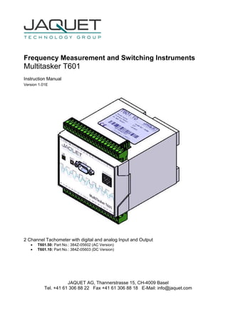
  • 1. Frequency Measurement and Switching Instruments Multitasker T601 Instruction Manual Version 1.01E 2 Channel Tachometer with digital and analog Input and Output • T601.50: Part No.: 384Z-05602 (AC Version) • T601.10: Part No.: 384Z-05603 (DC Version) JAQUET AG, Thannerstrasse 15, CH-4009 Basel Tel. +41 61 306 88 22 Fax +41 61 306 88 18 E-Mail: info@jaquet.com
  • 2. Instruction Manual T601 JAQUET AG Version 1.01E 2/70 Contents 1 SAFETY NOTICE 6 2 PRODUCT FEATURES 7 3 SPECIFICATIONS 8 3.1 General 8 3.2 Inputs 9 3.2.1 Sensor Inputs 9 3.2.2 Analog Input 11 3.3 Binary Inputs 12 3.4 CAN Input 12 3.5 Outputs 13 3.5.1 Analog Outputs 13 3.5.2 Relays Outputs 14 3.5.3 Open Collector Outputs 14 3.6 Data communication 15 3.6.1 Ethernet 15 3.6.2 Connection to the Display 15 3.7 Environment 15 3.7.1 Climatic Conditions 15 3.7.2 Electromagnetic immunity 15 3.7.3 Other Standards 15 4 PRINCIPLE OF OPERATION 16 4.1 General 16 4.2 Machine factor 18 4.2.1 Measured 18 4.2.2 Calculated 18 4.2.3 Other physical parameters 18 4.3 Datalogger 19 4.3.1 Min- Max value registers 19 4.3.2 Event Recorder 19 4.3.3 Trip Datalogger 19 5 INSTALLATION 21 6 CONNECTIONS 22 6.1 Front view 22 6.1.1 Front view T601 22 6.1.2 Terminal A 23 6.1.3 Terminal B 25 6.2 Top View 27
  • 3. Instruction Manual T601 JAQUET AG Version 1.01E 3/70 6.2.1 Terminal C 27 7 CONFIGURATION VIA PC SOFTWARE 28 7.1 Software Concept 28 7.2 PC Settings 28 7.3 Download configuration software 29 7.3.1 Direct execution 29 7.3.2 Save as 29 7.4 Configuration software 29 7.4.1 Configuration user and Process user 29 7.4.2 Log in 30 7.4.3 Main Window, Min-Max Values and System Limit Matrix 30 7.4.4 Logging in and out 31 7.5 Configuration file… 31 7.5.1 … creating new 31 7.5.2 … resetting to factory default 31 7.5.3 … loading 32 7.5.4 … saving 32 7.5.5 … printout 32 7.6 Communication with the Tachometer 33 7.6.1 Read measured data 33 7.6.2 Reading configuration from the T601 33 7.6.3 Writing a configuration to the T601 34 7.6.4 Compare data 34 7.6.5 Read and/or Delete Event Recorder 34 7.7 Configuring 35 7.7.1 Configure Speed Sensors 35 7.7.2 Configure Analog Sensor 36 7.7.3 Configure binary input 37 7.7.4 CAN 38 7.7.5 Set Measurement Interval 38 7.7.6 Sensor Alarm 39 7.7.7 Machine factor 39 7.7.8 Direction Sensing 40 7.7.9 Analog Input Range 40 7.7.10 Dynamic Error 40 7.7.11 Math Function 41 7.7.12 System Limits 42 7.7.13 Relay Outputs 43 7.7.14 Open Collector Outputs 44 7.7.15 Analog Output 45 7.7.16 Copy Parameter Set 46 7.7.17 Change-over delay 47 7.7.18 Data-logger Memory 48 7.8 Settings 48 7.8.1 Ethernet Interface 48 7.8.2 Time and Date settings 49 7.8.3 Changing the Password 49 7.8.4 Displays via Bluetooth® 50 7.8.5 Display Settings 51 7.9 Info 51
  • 4. Instruction Manual T601 JAQUET AG Version 1.01E 4/70 8 OPERATING BEHAVIOUR 52 8.1 Power on 52 8.1.1 Analog Output 52 8.1.2 Relay Output 52 8.1.3 Open Collector Output 52 8.2 Frequency Measurement 53 8.2.1 The Adaptive Trigger Level 53 8.2.2 Signal failure 54 8.3 Analog Input 54 8.4 Functions 54 8.4.1 “Exec“ Push button 54 8.4.2 Parameter sets A, B, C and D 54 8.4.3 Limits 54 8.4.4 Window Function 55 8.4.5 Rotational Direction 55 8.4.6 Creep Detection 56 8.4.7 Frequency x2 and x4 56 8.4.8 Relay and Open Collector Latch Function 57 8.4.9 Analog Output 57 8.5 Sensor Error 57 8.5.1 Sensor error 57 8.5.2 System alarm 57 8.6 Power failure 57 8.7 Behaviour during Configuration 57 9 MECHANICAL CONSTRUCTION / HOUSING 58 9.1 Tachometer 58 9.2 Mounting 59 10 ACCESSORIES 60 10.1.1 Interface cable 60 10.2 Display 60 10.2.1 Cable version 60 10.2.2 Bluetooth® Version 60 11 MAINTENANCE / REPAIR 61 12 SOFTWARE-VERSION 61 12.1 Configurations software 61 12.2 Firmware 61 13 WARRANTY 61 APPENDIX 62
  • 5. Instruction Manual T601 JAQUET AG Version 1.01E 5/70 A: Declaration of Conformity 62 B: Possible Problems 63
  • 6. Instruction Manual T601 JAQUET AG Version 1.01E 6/70 1 Safety notice Series T601 tachometers should only be connected by trained personnel. T601 tachometers do not generate dangerous potentials but as soon as circuits exhibiting dangerous potentials are connected, then these may be present in the tachometer circuits. • The Tachometers may only be opened for repair by trained personnel. • These Instruments correspond to protection class I. The PE terminal must therefore be earthed. • The instructions in this manual must be strictly adhered to. • Not following these instructions could result in damage to equipment or plant and injury to personnel, as well as negating warranty claims! • Units that have suffered electrical over load, mechanical stress or been operated outside of specification must be immediately switched off and returned to the manufacturer for repair. • These Instruments have been developed and produced in accordance with the IC-Publication 348 and left our factory in perfect condition.
  • 7. Instruction Manual T601 JAQUET AG Version 1.01E 7/70 2 Product features T601 Series tachometers measure and monitor frequency signals in the range 0.025Hz to 50kHz along with analog signals. The following functionality is provided: • 2 Frequency inputs (Speed sensor) • 1 Analog input for current or temperature (Pt100) • 2 Binary input • 2 Analog outputs • 4 Relays • 2 Open Collector outputs • 4 Parameter sets each having 6 System limits with 4 Limit values • Creep detection • Direction detection • Data logger function • Sensor monitoring • System monitoring T601’s are configured via Computer (PC) and a user program. Two tachometer models are offered: • T601.50: Part No. 384Z-05602 (AC Version) • T601.10: Part No. 384Z-05603 (DC Version)
  • 8. Instruction Manual T601 JAQUET AG Version 1.01E 8/70 3 Specifications Reference temp: + 20 °C 3.1 General Measurement interval 2 ms / 5 ms / 10 ms / 20 ms / 50 ms / 100 ms / 200 ms / 500 ms / 1 s / 2 s / 5 s (Under certain circumstances, frequency measurements can take several measurement intervals) Supply voltage AC Version 90…264 VAC (47...63 Hz) DC Version 18…36 VDC Isolation voltage AC Version 3000 VAC (of the AC/DC power supply) DC Version 1500 VDC (of the DC/DC converter) Isolation Galvanic isolation between: • Supply • Sensor input incl. sensor supply, analog input, CAN, Display • Binary input 1 • Binary input 2 • Analog output 1 • Analog output 2 • Relay outputs • Open Collector output 1 • Open Collector output 2 • Ethernet interface Power consumption T601 without Display T601 with D211 (Cable version) T601 with D201 (BlueTooth® version) P min. (W) P max. (W) P min. (W) P max. (W) P min. (W) P max. (W) AC Vers. 110 VAC 5.0 11.0 6.8 13.0 5.1 11.2 230 VAC 8.0 15.2 10.0 16.7 8.1 15.4 DC Vers. 18 VDC 3.0 7.5 4.4 8.8 3.2 7.7 24 VDC 3.0 7.4 4.4 8.7 3.2 7.6 36 VDC 3.2 7.5 4.6 8.8 3.4 7.7 Power supply bridging with P max. T601 without Display T601 with D211 (Cable version) T601 with D201 (BlueTooth® version) AC Vers. 110 VAC 39 ms 37 ms 31 ms 230 VAC 200 ms 190 ms 170 ms DC Vers. 18 VDC 7 ms 6.8 ms 5.5 ms 24 VDC 23 ms 22 ms 19 ms 25 VDC 26 ms 25 ms 22 ms 36 VDC 70 ms 67 ms 55 ms Operating temperature AC Version -25 °C…+50 °C DC Version -40 °C…+70 °C Storage temperature AC Version -40 °C…+85 °C DC Version Weight AC Version 450 g DC Version 400 g Sealing to DIN EN 60529 IP 20
  • 9. Instruction Manual T601 JAQUET AG Version 1.01E 9/70 3.2 Inputs 3.2.1 Sensor Inputs Number 2 Sensor inputs Frequency range (-3 dB) 0.025 Hz … 50 kHz Measurement range Programmable within the frequency range Measurement accuracy 0.002 % Resolution (Frequency) 10 ns Input impedance > 11.5 kΩ (0.1 Hz 80 kΩ, 1 kHz 18.5 kΩ, 10 kHz 16 kΩ, 50 kHz 11.6 kΩ) Input signal for fixed 3V trigger (+/-15 %) • Max. voltage: 80 VRMS (226 Vpp) • Best suited to digital signals • Schmitt Trigger Input (Hysteresis > 1 V) • „0“ = Low Level to 1.25 V • „1“ = High level from 3 V (+/- 15 %) • Min. pulse width: 5 µs • Not DC-decoupled Input signal for adaptive trigger min. 57 mVpp (+/-10 %) 20 mVRMS • Max. voltage: 80 VRMS (226 Vpp) • DC-decoupled • The Trigger level automatically adapts itself to the input signal in the range +28.5 mV to +2 V. The Adaptive Trigger improves the signal to noise immunity e.g. where electromagnetic sensors are used. Min. Trigger level: 57 mVpp +/-10% = 20 mVRMS +/-10% U min. = f(Frequency) 0.01 0.10 1.00 10.00 100.00 1000.00 0.01 0.1 1 10 100 1000 10000 100000 Frequency (Hz) SensorSignal(Vpp) O.K NOT O.K.
  • 10. Instruction Manual T601 JAQUET AG Version 1.01E 10/70 Input signal for adaptive trigger min. 500 mVpp (+/-10 %) 180 mVRMS • Max. voltage: 80 VRMS (226 Vpp) • DC-decoupled • The Trigger level automatically adapts itself to the input signal in the range +250 mV to +2 V. The Adaptive Trigger improves the signal to noise immunity e.g. where electromagnetic sensors are used. Min. Trigger level: 500 mVpp +/-10% = 180 mVRMS +/-10% U min. = f(Frequency) 0.1 1.0 10.0 100.0 1000.0 0.01 0.1 1 10 100 1000 10000 100000 Frequency (Hz) SensorSignal(Vpp) O.K. NOT O.K. Sensor supply • +14 V +/- 0.5 V, max. 35 mA / Short circuit proof • If the current limit has been activated, then the circuit needs to be disconnected to reset the protection. Typical voltage curve as a function of sensor current Sensor voltage = f (Sensor current) 13.6 13.8 14.0 14.2 14.4 14.6 14.8 0 5 10 15 20 25 30 35 40 45 Sensor current (mA) Sensorvoltage(V) Integral pull up resistor 1000 Ω to +14 V (Only for 2 wire active e.g. NAMUR sensors) Screen Terminals are provided for each sensor cable screen (Sh1 and Sh2). These terminals are internally connected to the ground of the sensor input.
  • 11. Instruction Manual T601 JAQUET AG Version 1.01E 11/70 Sensor monitoring 3 sensor monitoring settings are available in the configuration software: • No Sensor Monitoring • Monitoring of supplied sensors (active Sensor Types) [Also for 2 wire sensors that are supplied via the internal Pull-up resistor (1 kΩ) Sensors drawing current outside of Imin or Imax are considered to be faulty. Imin = 0.5…35 mA Imax = 0.5…35 mA • Monitoring of non powered sensors (passive Sensor Types) [For 2 wire sensors such as electromagnetic sensors.] The sensor is considered to be faulty if the line is broken. Here the sensor impedance is dynamically measured. Z < 60 kΩ = OK Z > 125 kΩ = NOT OK 3.2.2 Analog Input Number One 0/4 ..20 mA or 1 Temperature input (Pt100) 3.2.2.1 Analog Input as Current Input Resolution 12 Bit (4096 Steps) Max Linearity error 1 LSB (Least Significant Bit) ca. 5.37 uA Measurement error Max. 0.25 % of Measured value + 1 LSB (-25 °C +50 °C) Max. 0.50 % of Measured value + 1 LSB (-40 °C +70 °C) Accuracy class 0.2 % of final value Open circuit voltage Max. 13.7 VDC (active Sensor input) Driving voltage Min. 12 VDC (active Sensor input) External load Max. 600 Ω (active Sensor input) Internal current limit IMax = 24 mA+/-1 mA (active Sensor input) Measurement Impedance 50 Ω (passive Sensor input) Damping Hardware time constant T = 4.1 ms 10 % 90 % = 8.6 ms (Hardware) Actual time = Hardware time constant + Max. 1 Measurement interval Temperature Drift Typ.: 100 ppm/K, max. 150 ppm/K 3.2.2.2 Analogue Input as Temperature Input Measurement 2 wire or 3 wire Sensor Pt100 (Measurement current = 950 uA) Measuring range -50 °C +300 °C Accuracy +/-0.5 °C of the measurement value Max. cable resistance 28 Ω (3 Wire Measurement) Max. cable length, 3 wire measurement Cable resistance AWG Diameter Cross section Resistance Max. Length mm mm 2 Ω/km Pt100 T601 38 0.1 0.0082 2190 12.8 m 36 0.13 0.0127 1300 21.5 m 34 0.16 0.02 844 33.2 m 32 0.2 0.032 547 51.2 m 30 0.25 0.051 351 79.8 m 28 0.32 0.08 232 120.7 m 25 0.46 0.16 108 259.3 m 24 0.51 0.21 87.5 320.0 m 2 wire connection The cable must be kept as short as possible, since the cable resistance will be measured as well; e.g. a cable having 1 Ω (2 x 0.5 Ω wires) would introduce an error of about 2.5 °C.
  • 12. Instruction Manual T601 JAQUET AG Version 1.01E 12/70 Damping Hardware time constant T = 10 ms 10 % 90 % = 21 ms (Hardware) Actual time = Hardware time constant + Max. 1 Measurement interval 3.3 Binary Inputs Number 2 Active Binary Inputs and 1 push button (EXEC – logic OR with Binary input B1). Level Logic 0 = 0 V….+5 V Logic 1 = +15 V….+36 V Isolation voltage 1500 VRMS Input resistance Rmin = 8.2 kΩ 3.4 CAN Input All T600 digital inputs and outputs are represented in the Device Profile DS-404. In addition, 3 manufacturers binary inputs that influence the T600 process are defined in a specific profile area.
  • 13. Instruction Manual T601 JAQUET AG Version 1.01E 13/70 3.5 Outputs 3.5.1 Analog Outputs Number 2 Analog outputs Isolation voltage 1000 VDC Output type Current (selectable 0…20 mA / 4…20 mA) Load Max. 500 Ω Open circuit voltage Max. 15 V Typical error curve -1 -0.9 -0.8 -0.7 -0.6 -0.5 -0.4 -0.3 -0.2 -0.1 0 0.1 0.2 0.3 0.4 0.5 0.6 0.7 0.8 0.9 1 0.00E+00 1.00E-03 2.00E-03 3.00E-03 4.00E-03 5.00E-03 6.00E-03 7.00E-03 8.00E-03 9.00E-03 1.00E-02 1.10E-02 1.20E-02 1.30E-02 1.40E-02 1.50E-02 1.60E-02 1.70E-02 1.80E-02 1.90E-02 2.00E-02 I (A) Measurementerror(%) 0.2 % (from measured value) + 2 LSB CLASS 0.1 % (from End Value) Mode 20.5 20 12 4 0 Mode Output value 0...20mA 4...20mA Start value End value [mA] 21 2 Error level 4 … 20mA Error level 0 … 20mA Transfer Functions Start value < or > End value Outputvalue Output Startvalue < Endvalue Output Startvalue > Endvalue Outputvalue Resolution 14 Bit (16384 increments) Max. Linearity error 2 LSB (Least Significant Bit) approx. 2.7 uA Measuring error Max. 0.15 % f.m.v. + 2 LSB (-25 °C +50 °C) Max. 0.20 % f.m.v. + 2 LSB (-40 °C +70 °C)
  • 14. Instruction Manual T601 JAQUET AG Version 1.01E 14/70 Accuracy class 0.1 % of the end value Damping Hardware time constant T = 4.1 ms 10 % 90 % = 8.6 ms (Hardware) Actual time = Hardware time constant + Software setting (configuration) Temperature Drift Typ.: 50 ppm/K, max. 120 ppm/K 3.5.2 Relays Outputs Number 4 Relay output Type Mono-stable single change-over Functions • May be assigned to System Limit 1..6, Sensor Alarm, Static error Sensor 1 or 2, dynamic error, Static error Analog input, always on or off. • With or without Hold function (Reset via Binary input) • Fail Safe or Not Fail Safe Max. switching current Reaction time Effective Measurement interval + max 6 ms Contact resistance 50 mΩ Max. (Initial-contact) Contact isolation 1500 VAC (coil to contact) 1000 VAC (between open contacts) 3.5.3 Open Collector Outputs Number 2 Open Collector output Type Opto-coupler (passive) External resistance IC nominal = 15 mA (RPull-up = V / I) Example: V = 24 V R = 1.6 kΩ IC max. = 30 mA Reaction time • As Frequency output: <30 us • Effective Measurement interval + max 30 us Load voltage V = 5 VDC…36 VDC Isolation voltage 1500 VAC Functions • May be assigned to System Limit 1..6, Sensor Alarm, static error Sensor 1 or 2, dynamic error, static error Analog input, always ON or OFF, Frequency S1 or 2, Frequency x 2, Frequency x 4. • With or without hold function (Reset via Binary input) • Fail Safe or Not Fail Safe Inverting Open collector output frequencies are in phase with the input signal.
  • 15. Instruction Manual T601 JAQUET AG Version 1.01E 15/70 3.6 Data communication 3.6.1 Ethernet Number 1 Ethernet interface Physical Layer Ethernet 10Base-T, IEEE 802.3i Max cable length 100 m Transmission rate 10 MBit/s Connection Front panel, 8P8C (RJ45) Usage Configuration and measurement status Protocol Peer to Peer Connecting cable Use a crossover cable 3.6.2 Connection to the Display Number 1 Connector Plug (5 pins) Usage Connection to the Display 3.6.2.1 Cable Cable Complete 6m long cable to connect a display. See Chapter 10.2.1 Cable version 3.6.2.2 Bluetooth® Max. distance to the Display 10 m – 150 m Class Bluetooth® Class 1 + 7 dBm 3.7 Environment 3.7.1 Climatic Conditions Standard DIN 40 040 Operating temperature See 3.1 General Storage temperature See 3.1 General Relative humidity • 75 % average over 1 year; to 90 % for max. 30 days • Condensation to be avoided 3.7.2 Electromagnetic immunity Electrostatic discharge EN 61000-4-2 Contact 6 kV, air 8 kV Electromagnetic fields EN 61000-4-3 30 V/m, not modulated and AM 80 % with 1000Hz Sinus wave Fast transients EN 61000-4-4 2 kV, repeated 5 kHz duration 15 ms period 300 ms Slow transients EN 61000-4-5 Line / line +/- 1kV, earth line +/- 2kV, 1 per minute Conducted HF EN 61000-4-6 3 V eff (180 dBuV) 10 kHz – 80 MHz Mains frequency Magnetic field EN 61000-4-8 50 Hz, 100 A/m 2 minutes Voltage dips EN 61000-4-11 Voltage dips, short interruptions and voltage variations immunity tests 3.7.3 Other Standards Communauté Européenne
  • 16. Instruction Manual T601 JAQUET AG Version 1.01E 16/70 4 Principle of Operation 4.1 General T601’s are microprocessor controlled and operate on the period measurement principle whereby the input signal period is measured during the measurement interval. The frequency is determined from the reciprocal of the average input period. The relationship between frequency and speed is determined by the machine factor. The status of System Limits can be affected by various inputs. Inputs to System Limits may be logically combined AND or OR. System limit inputs may be: speed inputs, analog input, a math function of the 2 speed values or the analog input, both binary inputs, creep, direction, CAN interface. A hysteresis may be set in the case of both speed inputs, the analog input and the math function. The 6 System Limits may be variously defined in 4 parameter sets that may be selected via binary inputs. The 4 relays and 2 open collectors may be assigned to react to the System Limits. The 2 open collectors may alternatively be used to output the input frequency (f), frequency x2, frequency x4. In the case of limits, the relay and open collector status may be latched and then reset via binary input. The system permanently monitors itself. Sensors may in addition be monitored. Sensor alarm may be used in the configuration to influence System Limits. System error would influence the relays, open collectors and analog outputs and the front panel LED would go out. Frequency outputs (Open Collector Outputs) are not influenced by the machine factor but where so defined correspond to the input signal. For frequency x2 or x4 the 2 input signals should ideally be phase shifted by 90 degrees. Parameter input is via resident PC software and the Ethernet interface. This may also be used to interrogate the unit and display measurement and unit status. The parameters are safely stored in EEPROM.
  • 17. Instruction Manual T601 JAQUET AG Version 1.01E 17/70
  • 18. Instruction Manual T601 JAQUET AG Version 1.01E 18/70 4.2 Machine factor The Machine factor determines the relationship between the measured sensor frequency and the corresponding speed. There are two means of determining this value: 4.2.1 Measured Where the Frequency (f) at the Sensor input and the corresponding speed (n) is known: 4.2.2 Calculated The relationship between sensor signal frequency (f) and speed (n) at a pole wheel is: Machine factor is then: Should a gearbox be present between the pole wheel and drive shaft the formula becomes: The gearbox ratio is determined as follows: 4.2.3 Other physical parameters In principle any parameter may be processed as long as it can be translated into a frequency proportional value. The formulas above may still be applied whereby the required parameter is used in place of speed. n f M = M = Machine factor f = Signal frequency at machine speed n n = Machine speed n f M = M = Machine factor f = Signal frequency at known speed n = Machine speed at measured signal frequency f = Signal frequency in Hz n = Pole wheel speed in U/min (rpm) p = Number of teeth60 pn f × = 60 ip M × = M = Machine factor p = Number of teeth i = Gearbox ratio 1 2 2 1 p p n n i == i = Gearbox ratio n1 = Primary pole wheel speed (Sensor position) n2 = Secondary pole wheel speed (Speed to be indicated) p1 = Nr. of teeth – primary pole wheel p2 = Nr. of teeth – secondary pole wheel 60 p M = M = Machine factor p = Number of teeth
  • 19. Instruction Manual T601 JAQUET AG Version 1.01E 19/70 4.3 Datalogger This function is for the Firmware version 0.88 not available. 4.3.1 Min- Max value registers The minimum and maximum values of input signals S1 and S2 along with the analog value are measured and stored. The Min / Max registers may be reset via appropriately configured binary inputs (see 7.7.3) or via the configuration software (see 7.6.5 Event Recorder readout and / or reset). NB. If the Min / Max registers are reset via the configuration software, then the event and trip data recorders are reset as well! 4.3.2 Event Recorder The event recorder logs events such as when a relay operates or a system limit occurs. The following events are logged: • Relay 1 – 4 • Open Collector 1 and 2 (If assigned to a System Limit) • Binary input 1 and 2 • CAN Cell • Sensor alarm • System Limit 1 – 6 from the active parameter set • Creep • Direction • Sensor fault (Static Fault S1, Static Fault S2, Dynamic Fault, Static Fault Analog Input) 146 events can be recorded for each item in the list. Each event is time and date stamped. Every event has its own memory range. The event memory can be defined as Ring or Limited Memory. (see 7.7.18 Data-logger Memory) Time and date are only used for the event recorder and have no influence over other tachometer functions. In the event of power loss the clock will continue to operate for approx. 7 days. Thereafter it must be reset. (see 7.8.2 Time and Date settings) NB: If the memory is reset via the configuration software, then the event recorder, trip data logger and min / max registers are reset at the same time! 4.3.3 Trip Datalogger A Trip Data Logger is assigned to System Limit 1 in each parameter set. When activated by a System Limit 1 becoming active, 100 additional parameters before and after the trip event are logged. The additional parameters being: • Speed - Sensor S1 • Speed - Sensor S2 • Analog input value • Status – Binary input 1 • Status – Binary input 2 • CAN Cell status • Sensor alarm • Creep • Direction This function stores data for a fixed event window and needs to be reset via binary input to allow recording of further trip event data.
  • 20. Instruction Manual T601 JAQUET AG Version 1.01E 20/70 NB: If the memory is deleted via configuration software then the safety and event recorders along with the min / max registers are reset at the same time!
  • 21. Instruction Manual T601 JAQUET AG Version 1.01E 21/70 5 Installation Series T601 tachometers may only be installed by competent personnel. Only undamaged and correctly configured units may be used. Please note the safety instructions in chapter 1 Safety notice. They should be connected to the power supply by means of an isolating switch and correspond to protection class I. The PE terminal must therefore be earthed. Before switching on check that the supply is within the permissible range. The sensor cable screens must be connected to the terminals „Sh1“ and „Sh2“ respectively so as to minimize the effects of signal noise. These terminals are internally connected to 0V (not PE). Attention: If the password has been changed, there is no way of returning to a factory setup. If the password is forgotten, you have to send in the tachometer and the Jaquet-Service-Team will set it back.
  • 22. Instruction Manual T601 JAQUET AG Version 1.01E 22/70 6 Connections 6.1 Front view 6.1.1 Front view T601 The Ethernet and CAN interfaces along with the control LED and execute push button (EXEC) are all located at the front. A crossover Ethernet cable is required for configuration (see Chapter 7) Terminal B Terminal A
  • 23. Instruction Manual T601 JAQUET AG Version 1.01E 23/70 6.1.2 Terminal A Supply N (-) : Neutral (Return) P (+) : Live PE : Earth Binary inputs B1+ : positive B1 B1- : negative B1 B2+ : positive B2 B2- : negative B2 Sensor connections S1 / S2 S1 : Sensor input S1 Sh1 : Screen S1 V1+ : Sensor Supply S1 V1- : 0V S1 S2 : Sensor input S2 Sh2 : Screen S2 V2+ : Sensor Supply S2 V2- : 0V S2 Analog outputs I1+ : positive I1 I1- : negative I1 I2+ : positive I2 I2- : negative I2 Sh2 V2 - I2 - I2 + Sh1 V1 - S1 V1 + I1 - I1 + B2 - B2 + B1 - B1 + PEP + N - S2 V2 + + - Binary input Current output Power supply + - +-+- I1 I2 B2B1 Sensor 1 Sensor 2 For connection recommendation see below
  • 24. Instruction Manual T601 JAQUET AG Version 1.01E 24/70 Ferostatic sensors (2-wire) (DSF..., NAMUR) Sensors with NPN- output (open collector) (DSF..., DSD...) Electromagnetic 2-wire sensors (DSE..., Green Line E...) Sensors with amplifier and fixed trigger level at 1.25/3V (DC) (DSF..., DSD..., Greenline F..., D..., Y... ) or Sensor types or Configuration recommendation of the software parameters Connection recommendation Terminal for Sensor 1 Sh2 V2 - V1 + S2 V2 + Sh2I2 + Sh1 V1 - S1 V1 + +V S - + - + - MDR +V S - Terminal for Sensor 2
  • 25. Instruction Manual T601 JAQUET AG Version 1.01E 25/70 6.1.3 Terminal B Open Collector outputs Oc1 / Oc2 Oc1+ : positive Open Collector 1 (Emitter) Oc1- : negative Open Collector 1 (Collector) Oc2+ : positive Open Collector 2 (Emitter) Oc2- : negative Open Collector 2 (Collector) Relay outputs R1-R4 NC : Normally closed NO : Normally open Com : Common Analogeingang AIN1 : Terminal 1 AIN2 : Terminal 2 AIN3 : Terminal 3 temperature measurement + Sense (-) - current measurement + (active) - /+ (active / passive) - (passive) Oc2 + AIN 1 R4 com R4 no R4 nc Oc1 - Oc1 + Oc2 - R3 no R3 nc R2 nc R3 com R2 com R2 no R1 nc R1 com R1 no AIN 2 AIN 3 Relay output - Open Collector 1 nc no com + Open Collector 2 = Analog output For connecting recommendation, see below
  • 26. Instruction Manual T601 JAQUET AG Version 1.01E 26/70 Temperature measurement with Pt100 (3-wire technology) (...) Current measurement 0/4...20mA with passive current input (Loop powered by sensor) Temperature measurement with Pt100 (2-wire technology) (...) Current measurement 0/4...20mA with active current input (Loop power from T601) (loop powered sensors) Sensor types Configuration recommendation of the software parameters Connection recommendation Terminal for Analog input OC2 + AIN 1 AIN 2 AIN 3 T T or or
  • 27. Instruction Manual T601 JAQUET AG Version 1.01E 27/70 6.2 Top View Oc2 + AIN 1 R4 com R4 no R4 nc Oc1 - Oc1 + Oc2 - R3 no R3 nc R2 nc R3 com R2 com R2 no R1 nc R1 com R1 no AIN 2 AIN 3 6.2.1 Terminal C This connector is used to connect displays. Please refer to the operating instructions of the used display(s). Terminal C Pin 5 Pin 1
  • 28. Instruction Manual T601 JAQUET AG Version 1.01E 28/70 7 Configuration via PC Software 7.1 Software Concept The Ethernet interface is required to configure the T601 or view its measurement status. Settings are written to the T601 from a PC via a cross-over cable (see chapter 10 Accessories). The Configuration is done with a user friendly and self explanatory menu driven software. The software is resident in the T601 and needs to be downloaded for configuration. Normal file handling applies to the configured parameters and they may be printed out. To run the software Java Runtime Environment (JRE) 1.5 or higher is required. You can get the newest version online at www.java.com or you will find it on the CD-Rom. 7.2 PC Settings The PC Ethernet card must first be set correctly. T601’s cannot be used on a network. Go to Desktop, Settings, Network connections and right click on <Properties>. Right click the Network card you want to use for T601 comms and select <Properties>. Select Internet Protocol (TCP/IP) and select the option <Obtain an IP address automatically>
  • 29. Instruction Manual T601 JAQUET AG Version 1.01E 29/70 7.3 Download configuration software Connect the Tachometer to your PC using a cross over patch cable. Once connected open your internet browser and enter the IP address 192.168.1.127/software A HTML page will open with the link <Download control program> Click on the link. Dependent on your internet Explorer configuration you will be asked whether you want to <Open> (Run) or <Save> (Save as) the programme. NB: depending on your security settings, these functions will be denied. In this case, contact your administrator. 7.3.1 Direct execution Select <Open> and the configuration will be read from the tachometer (can take a few seconds). Once loaded the configuration software will open automatically. 7.3.2 Save as Select <Save> to save the file in a path of your choice (can take a few seconds). Open the file from your PC. The configuration software establishes a connection to the T601 and reads the actual parameters. 7.4 Configuration software 7.4.1 Configuration user and Process user T601 parameters are divided into 2 groups, Configuration and Process parameters. When the programme is started the window shows 3 levels one can log into, Config user, Process user or Guest. Process and Configuration users require passwords. A Guest has only the right to view measured data or print out actual parameters. Process users may execute all of the functions that a Guest can do. In addition he is able to view or set process parameters. Should a new file be loaded, only process parameters will be accepted (no configuration parameters). The Configuration user has full access and control over all parameters, Process as well as Configuration. The factory settings are shown below bold.
  • 30. Instruction Manual T601 JAQUET AG Version 1.01E 30/70 7.4.2 Log in Here you can Log in on three different levels. The standard passwords for Config- and Process- User are: Config user password 1981 Process user password 1977 7.4.3 Main Window, Min-Max Values and System Limit Matrix After successfully logging in, the main over view appears. Here one sees the various I/O’s and status. Listed on the left hand side are the various System Limit inputs. System Limit status and alarm messages are to be found in the middle. Shown on the right are all outputs status and output current levels. The measured Min-Max values are accessed via the button on the left. Actual measured values are shown alongside the Min-Max values for sensor signals 1 & 2 and the analog input. In the middle next to status is a further button through which an overview of the System Limit matrix is accessed, showing the logical status of System Limits, binary inputs etc.
  • 31. Instruction Manual T601 JAQUET AG Version 1.01E 31/70 7.4.4 Logging in and out To change user level log out via <File> and click on <Logout>, then log in again using the appropriate password. 7.5 Configuration file… 7.5.1 … creating new To create a new configuration file go to <File>, <New> and click on OK. All parameters are then reset. NB: if you have not saved the live parameters then they would be lost. 7.5.2 … resetting to factory default To reset parameters to factory settings go to <Settings> <Back to factory setup> then click on OK. NB: if you have not saved the live parameters then they would be lost.
  • 32. Instruction Manual T601 JAQUET AG Version 1.01E 32/70 7.5.3 … loading To load an existing file go to <File>, <Open> and select the required configuration file. NB: if you have not saved the live parameters then they would be lost. NB: you can only load parameters that your user level allows you to change. 7.5.4 … saving To save actual parameters go to <File>, <Save as> and choose the path and file name you want to use. Please note that the file name ends in the format *.T601. 7.5.5 … printout To print actual parameters go to <File>, <Print> and choose your printer. 9 pages will be printed.
  • 33. Instruction Manual T601 JAQUET AG Version 1.01E 33/70 7.6 Communication with the Tachometer 7.6.1 Read measured data To read actual measured data and unit status go to <Online>, <Start – read measure data>. Measured data is updated in the Main window with interval defined under <Settings>, <Refresh Interval>. ¼ Second ½ Second 1 Second 2 ½ Seconds 5 Seconds 10 Seconds To end the measured data display go to <Online>, <Stop – read measure data>. 7.6.2 Reading configuration from the T601 When the configuration software is started the configuration file is automatically transferred to the PC. To up load the file again go to <Online>, <Read parameters> and confirm with Enter. NB: The live parameter data will be overwritten.
  • 34. Instruction Manual T601 JAQUET AG Version 1.01E 34/70 7.6.3 Writing a configuration to the T601 Once the configuration is prepared it can be written to the T601. Go to <Online>, <Write parameters>. The parameters will then be sent to the tachometer. The process takes approximately 10 seconds. The T601 status during this period is described in chapter 8.7 Behaviour during Configuration. If no connection can be established, the process is repeated 3 times and then abandoned. NB: Actual tachometer data will be over written and the unit is in error mode during this period. 7.6.4 Compare data If you like to compare a PC configuration file with that in the T601, first open the file and then go to <Online>, <Compare Data>. The actual file is then uploaded from the T601 and compared with the software parameters. A dialogue window will then appear showing whether the files are identical or not. 7.6.5 Read and/or Delete Event Recorder This function is for the Firmware version 0.88 not available. To read out the contents of the event recorder and then delete it go to <Online>, <Read and delete memory>. After confirming with OK that you wish to read the data, it is loaded from the tachometer. That can take a few seconds. When reading the data you can define the destination to save it. For safety reasons you will be asked again whether you wish to delete the data. NB: After deleting the data it cannot be restored. If you only wish to read the data from the event recorder got to <Online>, <Read memory> After confirming with OK that you wish to read the data, it is loaded from the tachometer. If you only wish to delete the event recorder data go to <Online>, <Delete memory>, then confirm with OK.
  • 35. Instruction Manual T601 JAQUET AG Version 1.01E 35/70 7.7 Configuring 7.7.1 Configure Speed Sensors Go to <Configuration>, <Sensor>. To connect the sensor see chapter 6.1.2 Terminal A. 5 Parameters are used to configure the sensor: Type: powered / not powered Resistor: used / not used Min. current: 0.5mA … 35mA Max. current: 0.5mA … 35mA Trigger level: fixed 3V / min 57mVpp / min 500mVpp Sensor Type powered: The sensor is supplied from the Tachometer’s 14V (+/-0.5V) supply. To use static sensor monitoring the Min/Max current consumption must be defined. not powered: For sensors that aren’t powered by the Tachometer. Sensor monitoring is done via impedance measurement. Therefore a broken cable can be detected. not used: Sensor input is not used. Certain functions requiring 2 sensors are not available and will be automatically disabled. Internal pull up resistor not used: The internal pull up is not in circuit. used: The internal pull up is in circuit. Current monitoring When the sensor is supplied from the tachometer upper and lower current limits must be entered. Current consumption outside of the defined limits results in a static sensor error being signalled.
  • 36. Instruction Manual T601 JAQUET AG Version 1.01E 36/70 Trigger level One of 3 modes may be selected. Fixed trigger (fixed 3V) for digital sensors and two adaptive triggers (57 mVpp / 500 mVpp) for analog speed sensors (electromagnetic). 7.7.2 Configure Analog Sensor To configure the analog sensor input, go to <Configuration>, <Sensor>. How to connect the sensor to terminal B is shown in 6.1.3 Terminal B. There are 2 parameters available for configuration: Type: Pt100 / Current 4 .. 20mA / Current 0 .. 20mA Min. Sensor current: 0.5mA … 3.5mA … 35mA Sensor Type Pt100: Temperature sensor (Pt100) Current 4 .. 20mA: Current input 4mA … 20mA Current 0 .. 20mA: Current input 0mA … 20mA Current monitoring Static sensor fault is signalled if the current falls outside of the limits. The lower limit may only be selected where the sensor range is 4...20mA. The upper limit is fixed at > 20.5mA and cannot be adjusted.
  • 37. Instruction Manual T601 JAQUET AG Version 1.01E 37/70 7.7.3 Configure binary input To configure the binary inputs go to <Configuration>, Binary input>. There are 2 parameters available to configure: Logic level: Active High / Active Low Binary input for: Input to System Limits / Parameter set selection (A/B/C/D) / Latch reset / Creep reset / Min - Max value reset Logic levels Active High: Logic 1 = voltage in range on binary input Active Low: Logic 1 = no voltage on binary input Please see chapter 3.3 Binary Inputs for binary input voltage levels Binary input Binary inputs may be used for various functions. Input for System Limits: The binary input forms part of the logical combination for System Limit. Parameter set selection: Select parameter set A, B, C or D. See chapter 8.4.2. Reset latch / Open Collector: Reset latched relay and open collector Creep reset: Reset the Creep function Min / Max reset: Reset min / max values in the event recorder
  • 38. Instruction Manual T601 JAQUET AG Version 1.01E 38/70 7.7.4 CAN To set the CAN interface go to <Configuration>, <CAN>. To set up the interface the port must be enabled. Speed: 20kBit / 50kBit / 125kBit / 250kBit / 500kBit / 1MBit Node ID: 0 … 80 … 127 Activate: Yes / No 7.7.5 Set Measurement Interval Go to <Configuration>, <Measurement time>. This time interval determines the period during which the speed, parameters, status and outputs are recalculated and set accordingly. Measurement time: 2ms / 5ms / 10ms / 20ms / 50ms / 100ms / 200ms / 500ms / 1s / 2s / 5s
  • 39. Instruction Manual T601 JAQUET AG Version 1.01E 39/70 7.7.6 Sensor Alarm Go to <Configuration>, <Sensor alarm>. There are 4 possible error sources for sensor alarm that may be combined in a logic OR. Each individual error source may be independently selected. Static error sensor 1: On / Off Static error sensor 2: On / Off Dynamic error: On / Off Static error analog input: On / Off Box checked = On, unchecked = Off (see also chapter 7.7.1 Configure Speed Sensors). Dynamic Error can only be used when 2 sensors are present. (see chapter 7.7.10 Dynamic Error). Analog input static error occurs if the input falls outside of permitted limits. 7.7.7 Machine factor Go to <Configuration>, <System>. The machine factor establishes the relationship between sensor frequency and associated machine speed. (see chapter 4.2 Machine factor) The machine factor may also be set by means of the number of pulses per revolution. The 2 parameters have a fixed relationship of factor 60 (Pulses per rev. = Machine factor x 60) Machine factor: 0.0001 … 1 … 999,999 Pulses per revolution: 0.006 … 60 … 59,999,940 Once the machine factor has been established all further entries such as speed limits are in machine units e.g. rpm.
  • 40. Instruction Manual T601 JAQUET AG Version 1.01E 40/70 7.7.8 Direction Sensing To configure direction sensing go to <Configuration>, <System>. To use direction sensing, 2 sensors must be connected that optimally exhibit 90°phase shift (minimum 10°). The signal sequence that corresponds to clockwise rotation of the shaft must be defined Clockwise: S1 before S2 / S2 before S1 7.7.9 Analog Input Range To configure the analog input go to <Configuration>, <System>. The current value may be defined for inclusion in System Limits. The start value refers to 0/4mA according to the definition and the end value to 20mA input. Start value: -999'999 … 0.0 … 999’999 End value: -999'999 … 100.0 … 999’999 7.7.10 Dynamic Error Go to <Configuration>, <System>. ff SS Difference 21 −= fS1: Sensor 1 frequency fS2: Sensor 2 frequency This function is only available used when both sensor inputs are used. Deviation: 0.0 … 100.0 … 999’999 If the speed difference is bigger than this value, then Dynamic error is signalled.
  • 41. Instruction Manual T601 JAQUET AG Version 1.01E 41/70 7.7.11 Math Function Go to <Configuration>, <Math>. Math function is an additional input available for System Limit and current outputs The following Math functions may be constructed. S1 – S2 Subtraction of speed values S2 – S1 S1 / S2 Division of speed values S2 / S1 100% x (S1-S2)/S2 Percentage difference 100% x (S2-S1)/S1 Variance (S1) VarianceVariance (S2) Variance (Ain) Acceleration (S1) Speed value accelerationAcceleration (S2) Acceleration (Ain) S1 May also be used for the Window Function. S2 Ain Percentage difference 1 )12(100 n nn −× n: Speed Variance 2 1 2 )( 1 1 ∑= − − = j i ix xx j S j = 100 Acceleration altedgeSedgeS alt tt n t v a 11 11 − − = ∆ ∆ = n: Speed If the variance for S1, S2 or Analog input needs to be calculated, the measurement time must be set to 5ms or higher.
  • 42. Instruction Manual T601 JAQUET AG Version 1.01E 42/70 7.7.12 System Limits Go to <Configuration>, <System Limits>. Every System Limit has the same 9 logical inputs: sensor 1, sensor 2, analog input, math function, creep, direction, binary input 1, binary input 2 and CAN. A hysteresis may also be set for the first 4. Every input may be inverted and selectively assigned to the logical combination. The inputs may be logically combined OR or AND. Sensor alarm may be additionally combined OR with the System Limit result. Sensor 1: Limit low: 0.01 … 200.0 … 999’999 Limit high: 0.01 … 300.0 … 999’999 Sensor 2 Limit low: 0.01 … 400.0 … 999’999 Limit high: 0.01 … 500.0 … 999’999 Analog input for Pt100 Sensor: Limit low: -50 … 20.0 … 300 Limit high: -50 … 25.0 … 300 Analog input for current Sensor: Limit low: -999'999 … 50.0 … 999’999 Limit high: -999'999 … 100.0 … 999’999 Math function Limit low: -999’999 … 50.0 … 999’999 Limit high: -999’999 … 100.0 … 999’999 Inversion: Sensor 1: Over speed / Under speed Sensor 2: Over speed / Under speed Analog input: Over-run / Under-run Math: Over-run / Under-run Creep Creep / no Creep Rotational Direction CW / CCW Binary input 1: active / inactive Binary input 2: active / inactive Inclusion in logical combination: Sensor 1: On / Off On with system Limit 1 Sensor 2: On / Off On with system Limit 2 Analog input On / Off Math: On / Off On with system Limit 3 Creep On / Off Rotational Direction On / Off Binary input 1: On / Off On with system Limit 4 Binary input 2: On / Off On with system Limit 4 CAN On / Off Logical combination: Combined OR / AND Hysteresis Hysteresis may be defined for the first 3 inputs via upper and lower limits. If the lower limit is set higher than the upper limit, the hysteresis is inverted.
  • 43. Instruction Manual T601 JAQUET AG Version 1.01E 43/70 Inversion Every input may be inverted. Just select your event that triggers your system limit. Logical combination The box must be ticked to include the input in the logical combination. Sensor Alarm To OR Sensor alarm with the System Limit result the box must be ticked. 7.7.13 Relay Outputs To configure relay outputs go to <Configuration>, <Relay / Open Collector>. Relay configuration consists of: Assignment, the latch function and the fail safe/not fail safe mode. Latch Function: Latched / not latched Safety function: Fail safe / Not fail safe System limit 1 Sensor alarm System limit 2 Static S1 System limit 3 Static S2 System limit 4 Dynamic error System limit 5 Always ON System limit 6 Always OFF Static Ain
  • 44. Instruction Manual T601 JAQUET AG Version 1.01E 44/70 Assignment selection The selection box is used to choose relay assignment. Latch Function Defines whether a relay state should be held (Latched) until reset. Safety Function Defines whether the relay is to operate in Fail safe (deactivate at e.g. limit) or not fail safe mode (activate at e.g. limit). 7.7.14 Open Collector Outputs To configure the Open Collector outputs go to <Configuration>, <Relays / Open Collector> 3 parameters are available for configuration: Open Collector assignment, latch function and fail safe / not fail safe function System Limit 1 Dynamic error System Limit 2 Static Ain System Limit 3 Always ON System Limit 4 Always OFF System Limit 5 Frequency S1 System Limit 6 Frequency S2 Sensoralarm Frequency x2 Static S1 Frequency x4 Static S2 Latch Function: Latched / not latched Failsafe / not failsafe: Failsafe / not failsafe Assignment selection The selection box is used to choose Open Collector assignment.
  • 45. Instruction Manual T601 JAQUET AG Version 1.01E 45/70 Latch Function Defines whether an Open Collector state should be held (Latched) until reset. Safety Function Defines whether the Open Collector is to operate in Fail safe (deactivate at e.g. limit) or not fail safe mode (activate at e.g. limit). 7.7.15 Analog Output To configure analog outputs go to <Configuration>, <Analog out>. 4 parameters are available: Assignment, current range, start and end values and the time constant Assignment possibilities: Sensor 1 Analog output 1 Sensor 2 Analog output 2 Analog input Math value Current range: 0 ..20mA / 4 .. 20mA Start value: -999’999 … 0.0 … +999’999 End value: -999’999 … 2’000.0 … +999’999 Time constant 0 … 9.9 in 0.1 second increments Assignment selection The selection box is used to choose analog output assignment. Current range 0 … 20mA or 4 … 20mA Start and End values Enter the start and end values e.g. 0 (rpm) = 4mA 2000 (rpm) = 20mA If the end value is lower than the start value the output current follows a falling characteristic.
  • 46. Instruction Manual T601 JAQUET AG Version 1.01E 46/70 Time constant Sets a time constant T. The target value is reached after 5xT. The output current follows an e- Function. If the time constant is longer than 0 seconds, the measurement time must be set to 5ms or higher. 7.7.16 Copy Parameter Set Go to <Configuration>, <Copy from Control A>. A Parameter set may only be copied from Parameter set A! All parameter of the submenu <System>, <Math>, <System Limits>, <Relay / Open collector> and <Analog output> are members of the parameters sets. Therefore, the following Parameters will be copied: - Machine factor 1 and 2 - Deviation - Direction Sensing - Analog input range - Math function selection - Upper and lower limits in System Limits - System Limit inversion - Inclusion of input in the logical combination - Inclusion of sensor alarm in the logical combination - Relay / Open Collector assignment - Relay / Open Collector latch mode - Relay / Open Collector fail safe mode - Analog output assignment - 0..20mA or 4..20mA setting - Start and end values - Analog output time constant
  • 47. Instruction Manual T601 JAQUET AG Version 1.01E 47/70 7.7.17 Change-over delay Go to <Configuration>, <Delay>. One change-over delay may be set for the delay in switching from Parameter set B to Parameter set A only. Delay time: 0.0 … 2000 Seconds
  • 48. Instruction Manual T601 JAQUET AG Version 1.01E 48/70 7.7.18 Data-logger Memory This function is for the Firmware version 0.88 not available. To configure the data-logger go to <Configuration>, <Memory>. The memory may be organised as: Ring buffer or limited memory. Memory mode: Ring buffer / Limited memory Ring buffer: earlier data is over-written after a given number of values. Limited memory: a given number of values are stored. Once that value is reached no further data is saved. 7.8 Settings 7.8.1 Ethernet Interface Go to <Settings>, <Interface …>. No settings can be made. The PC-T601 connection is peer to peer (PC to PC). T601’s cannot be connected to a network! For technical data see chapter 3.6.1 Ethernet. DHCP Server ON / OFF TCP/IP Address 192.168.1.127 TCP/IP Mask 255.255.255.0
  • 49. Instruction Manual T601 JAQUET AG Version 1.01E 49/70 7.8.2 Time and Date settings Go to <Settings>, <Time setting>. To set the time enter the new time into the text field and click on <Set time>. Please keep to the format (hh:mm). To set the date enter the new date into the text field and click on <Set date>. Please keep to the format (dd.mm.yyyy). NB: The time and date settings have not yet been transferred to the tachometer. That only occurs when the parameters are sent to the unit. In the case of power loss, time and date are stored for approx. 7 days. Thereafter they must be re-enterred. 7.8.3 Changing the Password Go to <Settings>, <Change Config user password> or <Change Process user password>. Changing the password involves entering the old password and the new password twice. To save the password click on <OK>. The password is now stored in the configuration software. To change it in the T601 the data must be downloaded. A configuration user may change the process user password by entering the Configuration user password first. Factory set passwords: Config user: 1981 Process user 1977 Attention: If the password has been changed, there is no way of returning to a factory setup. If someone has forgotten the password, you have to send in the tachometer and we will set it back.
  • 50. Instruction Manual T601 JAQUET AG Version 1.01E 50/70 7.8.4 Displays via Bluetooth® To configure Display via Bluetooth® go to <Settings>, <Bluetooth Settings>. If you have connected a Bluetooth® Display or wish to connect an additional one, click on the button <Search for devices>. This search may take a few seconds. All Bluetooth® equipment found will be shown in a list. Then choose the required displays from the selection menu on the right to assign them to the tachometer. After assignment, the settings must be sent to the tachometer by clicking on the button <Save Settings>. This process can take a few seconds. NB: These settings are independent of the other parameters and do not form part of PC-T601 parameter transfers! To read the settings click on the button <Read Settings>. The actual settings are then displayed. This process can take a few seconds.
  • 51. Instruction Manual T601 JAQUET AG Version 1.01E 51/70 7.8.5 Display Settings To configure the display go to <Settings>, <Display Settings>. 18 values are available for display. Whether each value may be displayed can be independently selected. Further information is to be found in the display operating instructions. The display mode can be set for each value. Automatic: The decimal point is placed automatically Alternatively, the decimal point position may be fixed. In the case of values >100000, 100.0k may be used. Display the value: Yes / No (except variance) Mode: automatic / 0000.0 / 000.00 / 00.000 / 0.0000 / 100.0k If the variance should be shown on the display, the measurement time must be set to 5ms or higher. 7.9 Info To gain information about the Tachometer or to enter a process name <Info>, <Info about>. An individual process name may be entered into the text field to the right of <Process ID>, max. 16 characters. (Only alphanumeric characters). Type: Tachometer type number Java version: Configurations software of the Tachometer Firmware version: T601 Firmware Version Serial number: T601’s serial number Calibration date: Calibration date TCP/IP Address: T601’s IP Address JRE version: PC’s JAVA Runtime version
  • 52. Instruction Manual T601 JAQUET AG Version 1.01E 52/70 8 Operating behaviour 8.1 Power on The parameter set e.g. as defined by binary inputs is immediately valid. 8.1.1 Analog Output Immediately after power on the output corresponds to the lower range value set. Following the first measurement interval the output corresponds to the measured value. 8.1.2 Relay Output Up until the first measurement interval is completed, all relays are de-energised. Thereafter they assume the defined condition. If no input frequency is present then after measurement interval x 2, 0Hz is assumed. 8.1.3 Open Collector Output Up until the first measurement interval is completed, all Open Collectors are inactive. Thereafter they assume the defined condition. If the Open Collector is assigned to a frequency, then it immediately assumes the corresponding status. If no input frequency is present then after measurement interval x 2, 0Hz is assumed.
  • 53. Instruction Manual T601 JAQUET AG Version 1.01E 53/70 8.2 Frequency Measurement Every frequency measurement starts with the negative edge of the input signal. The last measured edge prior the end of the measurement interval completes the running measurement and immediately starts the next. An optimum measurement is achieved when the input period is shorter than the measurement interval. Input signal Input period Measurement End of the measurement interval Time If the input period is greater than the measurement interval, the frequency is calculated as follows: nt f × = tMeasuremen 1 n: Number of measurement intervals without input signal This continues until a second negative edge arrives. Input signal Input period Measurement End of the measurement interval Time The calculation and adjustment of outputs occurs immediately after the start of the next measurement interval. If the input frequency is lower than the lower limit (0.025Hz), then the output will be zero. The measurement of input frequencies above the upper limit (50kHz) is not guaranteed. 8.2.1 The Adaptive Trigger Level The trigger level is continuously adjusted for successive pulses. This guarantees that the trigger level can follow a 50% reduction in speed from pulse to pulse. DC offset, resonance and negative pulses have no effect on the triggering. t Triggerlevel signal to noise ratio bad Sensorsignal U Old Triggerlevel
  • 54. Instruction Manual T601 JAQUET AG Version 1.01E 54/70 8.2.2 Signal failure Signal failure is defined as the sudden transition from an input frequency to no further recognisable pulses. The frequency is then calculated as follows: nt f × = tMeasuremen 1 n: the number of Measurement intervals without an input signal The measured speed thereby follows an exponential function to the minimum frequency (0.025Hz) and then falls to zero. 8.3 Analog Input The analog input may be connected to a Pt100 temperature sensor or an analog signal (see 6.1.3 Terminal B) If a Pt100 is connected the resistance of the sensor is measured and converted into a temperature value based on the Pt100 characteristic. (Accuracy 0.5°C) . If an analog signal is connected it may be defined as 0 … 20mA or as 4mA … 20mA. NB: If the wrong configuration is selected the sensor may be damaged! (Pt100: I=950uA, Current output Imax = 24mA) 8.4 Functions 8.4.1 “Exec“ Push button The front panel “Exec“ button is ORed with binary input B1. Pushing the button executes the B1 function. 8.4.2 Parameter sets A, B, C and D Binary input configuration Status BIN 1 Status BIN 2 Selected Parameter set Binary input 1 to <Selection of Control A/B> Binary input 2 not to parameter set selection 0 X A 1 X B Binary input 1 not to parameter set selection Binary input 2 to <Selection of Control C/D> X 0 C X 1 D Binary input 1 to <Parameter set selection A/B> and Binary input 2 to <Parameter set selection C/D> 0 0 A 0 1 B 1 0 C 1 1 D For delay in switching between Parameter sets B and A see Paragraph 7.7.17 Change-over delay. 8.4.3 Limits User defined upper and lower limits allow wide or narrow hysteresis to be set. Unless otherwise required we recommend a hysteresis of 10%.
  • 55. Instruction Manual T601 JAQUET AG Version 1.01E 55/70 8.4.4 Window Function The Window function as implemented in earlier tachometers is realized in the T601 by means of the Math function. To set a Window function on a speed input please follow the steps below. (Example for Sensor 1): 1. Set the Math function to S1. 2. Set Math function and Sensor 1 hysteresis. 3. The Sensor – hysteresis gets the higher limit. 4. Math function must be set to under run. 5. All logic inputs must be switched off except Sensor 1 and Math function. 6. The two inputs must be combined OR. System limit settings 8.4.5 Rotational Direction 2 sensors are required for sense of direction. Ideally, the sensor signal phase relationship between the two should be 90°(minimum 10°). Digital (square wave) signals are required for precise evaluation, with sensor configuration as defined under 3.2.1 Sensor Inputs. Where signals from electromagnetic sensors are used these will first be digitised in the T601 prior to processing. However, the nature of electromagnetic signals is that there output voltage reduces with speed. This can therefore give rise to errors as the machine slows down to change direction.
  • 56. Instruction Manual T601 JAQUET AG Version 1.01E 56/70 8.4.6 Creep Detection This function allows discrimination between pole wheel rotation and jitter (vibration). Following a reset command via Binary input the sequence of the first 4 pulses is checked i.e. S1 > S2 > S1 > S2. The sequence may start with S1 or S2. Should irregularities arise after the first 4 pulses then that would not be recognised. S1 S2 No creep is, if the order of these four pulses isn’t correct. S1 S2 To check for shaft rotation again the creep detector needs to be reset via binary input (defined under 7.7.3 Configure binary input). 8.4.7 Frequency x2 and x4 A prerequisite for the x2 and x4 functions is that the 2 signals are synchronous, exhibit a phase shift close to 90°(minimum 10°) and a 50% Mark / Space ratio. The x2 function is an EXOR combination of the two input signals S1 and S2, with frequency limited to 35kHz. The x4 function comes from doubling of x2 and generates a 10us pulse for each positive and negative 'x2' edge. The Mark / Space ratio therefore changes with frequency, which is limited to 35kHz max. Frequency S1 Frequency S2 Frequency x2 Frequency x4 90° 10us
  • 57. Instruction Manual T601 JAQUET AG Version 1.01E 57/70 8.4.8 Relay and Open Collector Latch Function Relays and Open Collectors can be assigned a latch function. If a signal arrives from the assigned function the relay / OC is latched and remains latched until reset via binary input or the <Exec> button. Where fail safe mode is selected the deactivated Relay / Open Collector state is held. 8.4.9 Analog Output If an analog time constant higher than zero is set, with measurement interval of 2ms, then the max. frequency that can be measured is 35kHz. To measure frequencies higher than 35kHz with time constant higher than zero, a min. measurement interval of 5ms must be selected. 8.5 Sensor Error 8.5.1 Sensor error The sensors may be monitored in 3 ways. • Sensor powered by the T600 – Sensor supply current monitoring. If the current falls outside of the defined range then static error is signalled. • Sensor not powered by the T600 – Wire break detection. Static error is signalled when wire breakage occurs. (Impedance measurement of 2 wire sensor) • 2 speed sensors connected – Dynamic sensor monitoring, i.e. the 2 signals may be compared. If the values differ by more than the defined tolerance, dynamic error is signalled. The T601 behaviour in the event of a sensor fault is a function of the software configuration. If sensor monitoring is selected, a fault causes the LED to go off. Relay and analog output behaviour is a function of the configuration. 8.5.2 System alarm The microprocessor continuously monitors the following functions for errors: Supply, math functions of the micro controller, RAM, EEPROM. In the event of a fault the relays are de-activated, the current output goes to 2mA (4-20mA) or 21mA respectively and the Open Collectors become high resistance if assigned to a function other than frequency output. The T601 then initializes and attempts to run again. 8.6 Power failure If the power fails for longer than the bridging time the outputs are de-activated, i.e. Analog outputs go to 0mA, Relays de-activate and the Open Collectors go high resistance. As soon as the supply returns to the minimum required the T601 recommences its initialization routine. 8.7 Behaviour during Configuration During the transmission of configuration or process parameters to the tachometer, it goes into a safe mode, i.e. the outputs assume a defined state. For individual outputs that means: • Relays: are no longer powered • Open Collectors: become high resistance • Analog outputs:assume the fault mode according to the configuration
  • 58. Instruction Manual T601 JAQUET AG Version 1.01E 58/70 9 Mechanical Construction / Housing 9.1 Tachometer
  • 59. Instruction Manual T601 JAQUET AG Version 1.01E 59/70 9.2 Mounting Wall mounting Top hat rail mounting (as delivert)
  • 60. Instruction Manual T601 JAQUET AG Version 1.01E 60/70 10 Accessories 10.1.1 Interface cable Optional cable for computer – tachometer communications: • PC-T601, cross over, 2m: Part No. 830A-37649 • PC-T601, cross over, 5m: Part No. 830A-37650 10.2Display Two types of display are available for various process values: • Cable version, whereby the display has a fixed connection to the tachometer. • Bluetooth® Version, whereby up to 7 displays may be connected via Bluetooth® and used to display different process values. 10.2.1 Cable version Cables are available assembled or for self assembly. • D211.10 Display with assembled cable: Part No. 384Z-05729 • Cable with 2 connectors: Part No. 304F-73740 10.2.2 Bluetooth® Version Connecting 1...7 displays via Bluetooth® requires a Base Module connected to the tachometer and Bluetooth® displays. • Display Base Module: Part No. 384Z-05731 • D211.11 Display with Bluetooth®: Part No. 384Z-05730
  • 61. Instruction Manual T601 JAQUET AG Version 1.01E 61/70 11 Maintenance / Repair T601 s require no maintenance as they exhibit minimal drift and have no consumable components. When cleaning, please note the IP protection level. Wherever possible T601’s should be isolated from all power sources (including relay supplies) prior to cleaning. Surface cleaning may be only with a damp cloth. 12 Software-Version History and changes of the configuration software and firmware 12.1Configurations software Software version Changes 1.080428 First edit 12.2Firmware Firmware version Changes 0.88 First edit 13 Warranty The standard warranty in the event of a manufacturing defect confirmed by JAQUET consists of repair or replacement within 12 months of delivery. Ancillary costs are excluded as is damage caused by use outside the specification. Complaints concerning visible defects will only be accepted if advised to JAQUET within 14 days of receipt.
  • 62. Instruction Manual T601 JAQUET AG Version 1.01E 62/70 Appendix A: Declaration of Conformity
  • 63. Instruction Manual T601 JAQUET AG Version 1.01E 63/70 B: Possible Problems Neither green nor yellow LAN connector LED light up Cause: No physical (electrical) connection present. Solution: Check that a LAN Crossover cable is being used. Cause: Tachometer is unpowered. Solution: Check the supply connections and level. Cause: Computer network card is switched off or de-activated (energy save mode) Solution: • Open the Network Connections window. <Start> <Settings> <Control Panel> <Network Connections> • Click on the appropriate connection • Open the Menu <File> • Select <Deactivate> • Re-open Menu <File> • Select <Activate> Yellow LAN connector LED lights but no connection to browser Cause: Several instruments are connected to the same LAN as the tachometer. Solution: The tachometer only functions with a <Pier to Pier> connection. Remove the other equipment and insure that no hub, switch or router is connected between tachometer and computer. Cause: Computer LAN card not set correctly. Solution: Configure the card in accordance with chapter 7 Configuration via PC Software. If that does not solve the problem check that the network card is configured as follows: Go to Desktop, Settings, Network connections and right click on <Properties>. Right click on the network card you want to use and select <Properties>.
  • 64. Instruction Manual T601 JAQUET AG Version 1.01E 64/70 Select Internet protocol (TCP/IP) and select the options: <IP-Address automatically recognize> <DNS-Server address automatically recognize> Then select <Advanced>. Insure that: apart from the entries shown, no other entries are present. Select the tag <DNS> and insure that: no entries are present.
  • 65. Instruction Manual T601 JAQUET AG Version 1.01E 65/70 Select the tag <WINS> and insure that: no entries are present. NetBIOS- Setting is Standard. Confirm with <OK> Change to tag <Alternative Configuration>. Insure that: <Automatically allocated, private IP-Address> is selected. Confirm all settings with <OK> Confirm settings with <OK>
  • 66. Instruction Manual T601 JAQUET AG Version 1.01E 66/70 If you had to make changes you must now reset the LAN card: Enter the following commands: c: ipconfig /flushdns ipconfig /release ipconfig /renew The tachometer responds with incomprehensible hieroglyphics Cause: Your browser and computer interpret the address incorrectly. Solution: Extend the address with a forward slash: http://192.168.1.127/software/ Problems when using Microsoft Internet Explorer Cause: Your browser and computer interpret the address incorrectly. Solution: • Close Internet Explorer • Restart Internet Explorer • Wait until IE has fully loaded and the computer is inactive. • Call the tachometer using the address: http://192.168.1.127/software/
  • 67. Instruction Manual T601 JAQUET AG Version 1.01E 67/70 Solution: Should the solution above not work, go to the menu <Extras> and select <Internet options> Click on <Security> Select <Adjust level> Change setting to „Medium“ Click on <Reset> Click on <OK> Click <OK> again Start IE again and proceed as described in the operating instructions. The first page is shown correctly but after selecting Download nothing happens Cause: The IE security level is too restrictive. Solution: Set the security level to „Medium“. In the Menu <Extras> select <Internet options> Change tab to <Security> Select <Adjust Level>
  • 68. Instruction Manual T601 JAQUET AG Version 1.01E 68/70 Change settings to „Medium“ Click on <Reset> Click <OK> Click <OK> again Start IE again and proceed as described in the operating instructions. Solution: Should you not be able to change these settings we recommend you try the browser Firefox (freeware). Problems using Internet Browser Mozilla Cause: „Ping“ works but an error message appears - Proxy Server not found. A Proxy Server is defined. Solution: Avoid the Proxy- Server. In the Menu <Extras> select <Settings> Change the tab to <Network> Select <Settings>
  • 69. Instruction Manual T601 JAQUET AG Version 1.01E 69/70 Select <Direct Connection to Internet> Confirm with <OK> How do I see which Java Version is installed on my PC? Solution (Win XP) Go to <Control Panel> And select <Java> (the coffee cup)
  • 70. Instruction Manual T601 JAQUET AG Version 1.01E 70/70 Select <Application Info…> Further information on Java-Technologies and Applications can be seen at http://www.java.com