SlideShare a Scribd company logo
1 of 29
Download to read offline
GLOBAL COLLEGE OF ENGINEERING &TECHNOLOGY: YSR DIST.
  Unit –I            OPTICS - Interference    Engineering Physics
1. Introduction
               In the 17th century, the properties of light were explained by Sir Isaac Newton
and Christian Huygens. Sir Isaac Newton was explained the properties of light by introducing
corpuscular theory in 1675. It explains reflection, refraction and dispersion properties of light.
It fails to explain interference, diffraction, polarization, photo electric effect and double
refraction.
        In 1679, Christian Huygens proposed the wave theory of light. According to Huygen’s
wave theory, each point on the wave front is to be considered as a source of secondary
wavelets. It explains reflection, refraction, dispersion, double refraction, diffraction,
interference and polarization properties of light. It fails to explain, photo electric effect, black


                                                                              m
body radiation etc,.

2. Coherence


                                                                        .co
       Coherence is a property of waves. Two produce interference pattern coherent sources
are required. Coherent light sources cannot be obtained from the separate light sources, but
they are obtained from the single light source.


                                                                 bly
Two waves are said to be coherent, the waves must have
  • Same wavelength
  • Same amplitude and


                                                            ee
  • Constant phase difference                       s.w
Definition:-

       A predictable correlation of the amplitude and phase at any one point with other point is
called coherence.
                                              sic

There are two types of coherence

      i) Temporal coherence (or longitudinal coherence)
                                      hy


      ii) Spatial coherence (or transverse coherence)

Temporal coherence (or longitudinal coherence):-
                              gp


         It is possible to predict the amplitude the amplitude and phase at a one point on the
                      in


wave w.r.t another point on the same wave, then the wave is in temporal coherence.
         To understand this, let us consider two points P1 and P2 on the same wave as in shown
                   er


in figure. Suppose the phase and amplitude at any one point is known, then we can easily
calculate the amplitude and phase for any other point on the same wave by using the wave
             e


equation
                                                  2ߨ
                                       ‫ ݕ‬ൌ ܽ sin ቆ ሺܿ ‫ ݐ‬െ ‫ݔ‬ሻቇ
          gin


                                                   ߣ
Where ‘a’ is the amplitude of the wave and ‘x’ is the displacement of the wave at any instant of
time‘t’.
    en


                               P1
                                           P2
Spatial coherence (or transverse coherence)
      It is possible to predict the amplitude the amplitude and phase at a one point on the
wave w.r.t another point on the second wave, then the wave is in spatial coherence.


      P.Sreenivasula Reddy   M.Sc, (PhD)   Website: www.engineeringphysics.weebly.com   Page 1
Independent sources are not coherent
       Two independent sources of light with same power can never be treated as coherent
sources; even it emits same wavelength and same amplitude waves. Generally the light is
emitted from the source through spontaneous emission process. But the waves emitted
trough spontaneous emission process is in out of phase. So two waves generated by two light
sources are always in out of coherence. Even the waves are emitted from the different parts of
the lamp, no longer they are coherent.

3. Principle of superposition of waves
Definition:-
       Principle of superposition of waves states that, the resultant displacement of two or
more waves traveling simultaneously in a medium at any point is equal to the algebraic sum of
the displacements due to individual waves.


                                                                          m
      To understand this concept, Let us consider two waves traveling simultaneously in the


                                                                         .co
medium. Let ܻଵ and ܻଶ are the displacements of first and second waves at any point in the
absence of other.
      According to principle of superposition, the resultant displacement ሺܻሻ of two waves


                                                                bly
can be written as
                                       ܻ ൌ ܻଵ േ ܻଶ


                                                           ee
   Wave 1
                         +
                                             =
                                                  s.w
  Wave 2

Let two waves are in phase, their resultant amplitude is
                                          ܻ ൌ ܻଵ ൅ ܻଶ
                                            sic

Two waves are in opposite phase, their resultant amplitude is
                                          ܻ ൌ ܻଵ ~ ܻଶ
                                       hy


   Wave 1
                                   gp


                         +                   =
  Wave 2
                             in
                          er


4. Young’s double slit experiment

       The first experimental evidence of interference pattern was given by Thomas Young In
                    e


1801. He explained the interference pattern based on the wave nature of light.
                 gin


Experimental setup:
       His experimental arrangement is shown in figure. He passed the sun light through a
narrow pin hole S on a opaque surface and then through closely spaced pin holes S1 and S2
in another opaque surface. A screen XY was arranged in front of the pin holes S1 and S2. He
               en


observed few coloured bright and dark bands on the screen. Now a day, the pin holes are
replaced by slits and sun light is replaced by monochromatic light.

                                                                X

                                                 S1

                                                 S2
                               S                                Screen


                                                                Y
GLOBAL COLLEGE OF ENGINEERING &TECHNOLOGY: YSR DIST.
  Unit –I            OPTICS - Interference    Engineering Physics
Explanation of wave theory
        When sun light is passes through pin hole S, spherical waves are spread out.
According to Huygen’s wave theory, each point on the wave front is to be considered as a
source of secondary wavelets. Hence spherical waves also spread out from pin holes S1 and
S2. The radii of the wave fronts increase as they move away from S1 and S2 and hence
superimpose on each other.
        In the above figure, continuous circular arcs represent the wave crests while dotted
circular arcs represent the troughs of each wave. A crest fall on the other crest constructive
interference will occurs and their resultant amplitude is equal to the sum of the amplitudes
individual waves.
                                           ܻ ൌ ܻଵ ൅ ܻଶ


                                                                               m
        A crest fall on the other trough destructive interference will occurs and their resultant


                                                                         .co
amplitude is equal to the difference of the amplitudes of individual waves.
                                           ܻ ൌ ܻଵ െ ܻଶ
Thus a number of dark and bright bands having equal width is observed on the screen.


                                                                  bly
5. Interference of light

       The best evidence for the wave nature of light is interference phenomenon. This was


                                                             ee
experimentally demonstrated by Thomas Young in 180, through double slit experiment. Due
to interference, we will observe many observations in our day today life, such as multiple
                                                     s.w
colours on soap bubbles as well as on oil film when viewed under sun light. Interference
concept is explained on the basis of superposition of wave’s concept.
              When two light waves superimpose, then the resultant amplitude or intensity in
                                               sic

the region of superposition is different than the amplitude of individual waves.

Definition:-
                                       hy


       The modification in the distribution of intensity in the region of superposition is known
as interference.
                               gp


In case of interference pattern we observe two cases
   •   Constructive interference
                       in


   •   Destructive interference
                    er


Constructive interference
              e


  The waves are reaching at a point are in phase constructive interference occurs
  In constructive interference, the resultant amplitude is always equal to the sum of the
           gin


  amplitudes of two individual waves.
   Condition
       en


       The path difference between the two waves is equal to the integral multiple of wave
length ሺߣሻ the constructive interference occurs.
‫ ݁ܿ݊݁ݎ݂݁݅݀ ݄ݐܽ݌‬ൌ ݊ߣ         Where n = 0, 1, 2, 3, 4 …


   Wave 1
                              +
                                                        =
  Wave 2


       P.Sreenivasula Reddy   M.Sc, (PhD)   Website: www.engineeringphysics.weebly.com   Page 3
Destructive interference
  The waves are reaching at a point are in out of phase desstructive interference occurs
  In Destructive interference, the resultant amplitude is always equal to the difference of the
  amplitudes of two individual waves.
   Condition
      The path difference between the two waves is equal to the odd integral multiple of λ/2
destructive interference occurs
                    ሺ2݊ െ 1ሻߣ
‫ ݁ܿ݊݁ݎ݂݁݅݀ ݄ݐܽ݌‬ൌ                 Where n ൌ 1, 2, 3, 4 … ‫ݎ݋‬
                        2
                     ሺଶ௡ାଵሻఒ
‫ ݁ܿ݊݁ݎ݂݁݅݀ ݄ݐܽ݌‬ൌ                    Where n ൌ 0, 1, 2, 3, 4 …
                        ଶ


                                                                           m
   Wave 1
                         +


                                                                     .co
                                              =
  Wave 2


                                                                bly
6. Types of interference:-
       For the formation of interference pattern, two coherent light sources are required. To


                                                         ee
get two coherent sources form a single light source, two techniques are used. They are
   1. Division of wave front
   2. Division of amplitude
                                                  s.w
Division of wave front
        The wave front from a single light source is divided into two parts using the
phenomenon of reflection, refraction or diffraction. Young’s double slit experiment is belongs
                                              sic

to this class of interference.
Division of amplitude
        The amplitude of a single light beam is divided into two parts by parallel reflection or
                                       hy


refraction. Newton’s ring experiment, Michelson’s interferometer is belongs to this class of
interference.
                                  gp


7. Conditions for interference
                               in


   1)   Two light sources of emitting light waves should be coherent.
   2)   Two sources must emit continuous light waves of same wavelengths or frequency.
                            er


   3)   The separation between the two sources should be small.
   4)   The distance between the two sources and the screen should be large.
   5)   To view interference fringes, the background should be dark.
                     e


   6)   The amplitude of light waves should be equal or nearly equal.
                  gin


   7)   The sources should be narrow.
   8)   The sources should be monochromatic.
8. Interference in thin films by reflection
             en


Principle:-
        The formation of colours in thin films can explained as due to the phenomenon of
interference. In this example, the formation of interference pattern is by the division of
amplitude.
 .       Consider a thin film of uniform thickness ’‫ ’ݐ‬and refractive index ‘µ’. Let a
 monochromatic light ray AB is incident is on the upper surface of the film with an angle ‘i’.
 This ray is partially reflected along BC and the remaining part is refracted along BD with an
 angle ‘r’. The refracted ray BD is reflected into DE from the lower surface of the film and it
 emerges through the film in the form of light ray EF. The two light rays BC and EF are parallel
 and superimpose and produce interference. The intensity of interference fringe depends up
 on the path difference between the ray 1 and ray 2.
GLOBAL COLLEGE OF ENGINEERING &TECHNOLOGY: YSR DIST.
Unit –I            OPTICS - Interference    Engineering Physics
                                                                               Ray 1

                                                                                  Ray 2


                                                                                       m
                                                                               .co
                                                                       bly
           To find out the path difference between the light rays (1) and (2), draw one


                                                             ee
   normal DG to BE and from point E to BC. From point E and H onwards the two light
   rays 1 and 2 travels equal distances. By the time the light ray 1 travels from B to H, the
                                                  s.w
   transmitted ray has to travel from B to C and D to E.
   The path difference between the light rays (1) and (2) is
   ‫ ݁ܿ݊݁ݎ݂݂݁݅݀ ݄ݐܽ݌‬ൌ ߤሺ‫ ܦܤ‬൅ ‫ܧܦ‬ሻ ݅݊ ݂݈݅݉ െ ‫ݎ݅ܽ ݊݅ ܪܤ‬                                               (1)
                                            sic

                                                            ஽ீ         ௧
   From ∆‫ܩܦܤ‬                                  cos ‫ ݎ‬ൌ            ൌ
                                                            ஻஽        ஻஽
                                                              ‫ݐ‬
                                    hy


                                                ‫ ܦܤ‬ൌ
                                                            cos ‫ݎ‬
                            gp


                                                             ஽ீ            ௧
Similarly from ∆‫ܩܧܦ‬                             cos ‫ ݎ‬ൌ           ൌ
                                                             ஽ா        ஽ா
                                                               ‫ݐ‬
                   in


                                                  ‫ ܧܦ‬ൌ
                                                             cos ‫ݎ‬
                er


                                                                  ௧
                                         ‫ ܦܤ ׵‬ൌ ‫ ܧܦ‬ൌ                                              (2)
                                                              ௖௢௦ ௥
          e


                                                       ஻ு         ஻ு
                 ∆‫ܪܧܤ‬                        sin ݅ ൌ        ൌ ஻ீାீா
       gin


From
                                                       ஻ா

‫ ܪܤ ׵‬ൌ ሺ‫ ܩܤ‬൅ ‫ܧܩ‬ሻ. sin ݅
From ∆‫ܩܧܦ∆ ݀݊ܽ ܩܦܤ‬                             ‫ ܩܤ‬ൌ ‫ ܧܩ‬ൌ ‫ ݐ‬tan ‫ݎ‬
 en


‫ ܪܤ‬ൌ ሺ2‫ ݐ‬tan ‫ݎ‬ሻ. sin ݅
From Snell’s law at point B
                                                  sin ݅ ൌ ߤ sin ‫ݎ‬
                           ‫ ܪܤ ׵‬ൌ 2ߤ‫ ݐ‬tan ‫ . ݎ‬sin ‫ݎ‬                                    (3)
Substituting the equations (2) and (3) in equation (1), we get
                         ଶఓ௧
ܲܽ‫ ݁ܿ݊݁ݎ݂݂݁݅݀ ݄ݐ‬ൌ ୡ୭ୱ ௥ െ 2ߤ‫ ݐ‬tan ‫ . ݎ‬sin ‫ݎ‬


  P.Sreenivasula Reddy     M.Sc, (PhD)   Website: www.engineeringphysics.weebly.com          Page 5
2ߤ‫ݐ‬          sin ଶ ‫ݎ‬
                                          ൌ       െ 2ߤ‫.ݐ‬
                                            cos ‫ݎ‬          cos ‫ݎ‬
                                             2ߤ‫ݐ‬
                                          ൌ       ሺ1 െ sin ଶ ‫ݎ‬ሻ
                                            cos ‫ݎ‬
                                             2ߤ‫ݐ‬
                                          ൌ       ܿ‫ ݏ݋‬ଶ ‫ݎ‬
                                            cos ‫ݎ‬
                                          =2ߤ‫ ݐ‬cos ‫ݎ‬
    At point B the light ray (1) is reflected at the surface of thin film (denser medium). So the
   light ray (1) undergoes a phase change π or an additional path difference λ/2.
                                          ఒ
    Total path difference ൌ 2ߤ‫ ݐ‬cos ‫ ݎ‬െ ଶ
   Constructive interference (or Bright fridge)


                                                                            m
   General condition; ‫ ݁ܿ݊݁ݎ݂݂݄݁݅݀ݐܽ݌‬ൌ ݊ߣ
                                                      ߣ
                                          2ߤ‫ ݐ‬cos ‫ ݎ‬െ   ൌ ݊ߣ


                                                                     .co
                                                      2
                                                           ߣ
                                          2ߤ‫ ݐ‬cos ‫ ݎ‬ൌ ݊ߣ ൅
                                                           2


                                                                    bly
                                                     ሺ2݊ ൅ 1ሻߣ
                                         2ߤ‫ ݐ‬cos ‫ ݎ‬ൌ
                                                         2


                                                             ee
   Destructive interference (or Dark fridge)
                                                ఒ
   General condition: ‫ ݁ܿ݊݁ݎ݂݂݄݁݅݀ݐܽ݌‬ൌ ሺ2݊ ൅ 1ሻ ଶ
                                                       s.w
                                                   ߣ ሺ2݊ െ 1ሻߣ
                                     2ߤ‫ ݐ‬cos ‫ ݎ‬െ     ൌ
                                                   2     2
                                            2ߤ‫ ݐ‬cos ‫ ݎ‬ൌ ݊ߣ
                                              sic

9. Newton’s rings
                                         hy


Principle:-
        The formation of Newton’s rings can explained as due to the phenomenon of
                                  gp


interference. In this example, the formation of interference pattern is obtained by the division
of amplitude.
                             in


Experimental arrangement
                          er


     The experimental arrangement of
Newton’s rings is shown in figure.
                    e


The Plano -convex lens (L) of large
                 gin


radius of curvature is placed with its
                                                                      M
convex surface on the glass plate (P).
The lens touches the glass plate at
              en


O. A monochromatic light is allowed
to fall normally on the lens with the
help of glass plate M kept at 450 to
the incident monochromatic light.

        A part of light is reflected by
the curved surface of the lens ‘L’ and
a part of light is transmitted is partly                    O
reflected back by the upper surface of
the plane glass plate P as shown in figure. These reflected rays interfere and give rise to an
interference pattern in the form of circular fringes. These rings are seen through microscope.
GLOBAL COLLEGE OF ENGINEERING &TECHNOLOGY: YSR DIST.
  Unit –I            OPTICS - Interference    Engineering Physics
Explanation of formation of Newton’s rings

       Newton’s rings are formed due to the interference between the light rays reflected from
the lower surface of the lens and the upper surface of the glass plate (or top and bottom
surfaces of the air film).
       Let R be the radius of curvature of the lens and ‫ ݐ‬be the thickness of the air film at point
P. At point P a part of the incident monochromatic light is reflected from the bottom surface of
the glass plate without phase change. The other part of the light is refracted from the upper
surface of glass plate with additional phase change of π or path difference λ/2.
The path difference between the two rays is
                                                      ߣ


                                                                                    m
                                          2ߤ‫ ݐ‬cos ‫ ݎ‬൅
                                                      2
For air film ߤ ൌ 1 and for normal incidence ‫ ݎ‬ൌ 0, so


                                                                              .co
                             ఒ
The path difference ൌ 2‫ ݐ‬൅
                             ଶ


                                                                       bly
Constructive interference (or Bright fridge)
General condition: ‫ ݁ܿ݊݁ݎ݂݂݄݁݅݀ݐܽ݌‬ൌ ݊ߣ
                                                           ߣ
                                                    2‫ ݐ‬൅     ൌ ݊ߣ
                                                           2


                                                                   ee
                                                                      ߣ
                                                  2‫ ݐ‬ൌ ሺ2݊ െ 1ሻ
                                                                      2
Where ݊ ൌ 0, 1, 2, … … … ..
                                                       s.w
Destructive interference (or Dark fridge)
                                             ఒ
General condition: ‫ ݁ܿ݊݁ݎ݂݂݄݁݅݀ݐܽ݌‬ൌ ሺ2݊ ൅ 1ሻ ଶ
                                               sic

                                                       ߣ            ߣ
                                                2‫ ݐ‬൅     ൌ ሺ2݊ ൅ 1ሻ
                                                       2            2
                                       hy


                                                       2‫ ݐ‬ൌ ݊ ߣ
Where ݊ ൌ 0, 1, 2, … … … ..
                               gp


                                                               ఒ
At the point of contact ‫ ݐ‬ൌ 0, path difference is              ଶ
                                                                   i.e., the reflected and incidence light are out
                       in


of phase and destructive interference occur. So the center fringe is always dark.
Theory of Newton’s rings
                    er


         To find the diameters of a dark and bright fringes construct a circle with the radius of
curvature R of a lens L and let us choose a point P at a distance ‘r’ from the center of lens and
             e


‫ ݐ‬be the thickness of air film at point ܲ.
          gin


From the property of a circle ܰܲ. ܰ‫ ܤ‬ൌ ܱܰ. ܰ‫ܦ‬
                      ‫ ݎ .ݎ‬ൌ ܶ. ሺ2‫ ݎ‬െ ‫ݐ‬ሻ
                         ‫ ݎ‬ଶ ൌ 2ܴ‫ ݐ‬െ ‫ ݐ‬ଶ
    en


If t is small ‫ ݐ‬ଶ is negligible.
         ‫ ݎ‬ଶ ൌ 2ܴ‫ݐ‬
                                 ‫ݎ‬ଶ                               r       r
                            ‫ݐ‬ൌ
                                2ܴ
Bright rings
                                                           ఒ
For bright ring, the condition is 2‫ ݐ‬ൌ ሺ2݊ െ 1ሻ ଶ
                 2 ‫ݎ‬ଶ            ߣ
                      ൌ ሺ2݊ െ 1ሻ
                 2ܴ              2
                                                         ሺ2݊ െ 1ሻߣܴ
                                                  ‫ݎ‬ଶ ൌ
                                                              2
      P.Sreenivasula Reddy    M.Sc, (PhD)   Website: www.engineeringphysics.weebly.com        Page 7
By replacing r by D/2 the diameter of the bright ring is
                                        ‫ܦ‬ଶ ሺ2݊ െ 1ሻߣܴ
                                          ൌ
                                        4       2
                                        ‫ܦ‬ଶ ൌ 2ሺ2݊ െ 1ሻߣܴ
                                       ‫ ܦ‬ൌ ඥ2ሺ2݊ െ 1ሻߣܴ

                                       ‫ ܦ‬ൌ ඥሺ2݊ െ 1ሻ√2ߣܴ

                                          ‫ ן ܦ‬ඥሺ2݊ െ 1ሻ
‫ݎܾ݁݉ݑ݊ ݈ܽݎݑݐܽ݊ ݀݀݋√ ן ܦ‬
Dark rings


                                                                            m
For dark rings, the condition is
                                             2‫ ݐ‬ൌ ݊ ߣ


                                                                      .co
                                             2 ‫ݎ‬ଶ
                                                  ൌ݊ߣ
                                             2ܴ


                                                                bly
                                             ‫ ݎ‬ଶ ൌ ݊ ߣܴ
By replacing r by D/2 the diameter of the nth dark ring is


                                                             ee
                                             ‫ܦ‬ଶ
                                                ൌ ݊ ߣܴ
                                             4
                                                       s.w
                                           ‫ ܦ‬ൌ √4݊ ߣܴ
                                           ‫ ܦ‬ൌ 2√݊ ߣܴ
                                              ‫݊√ ן ܦ‬
                                              sic


                                      ‫ݎܾ݁݉ݑ݊ ݈ܽݎݑݐܽ݊√ ן ܦ‬
                                         hy


Note: suppose a liquid is taken in between the lens and glass plate having refractive index ߤ,
then the diameter of the dark nth dark ring can be written as
                                   gp


                                                √4݊ ߣܴ
                                           ‫ܦ‬ൌ
                                                  ߤ
                              in


10. Determination of wave length of sodium light using Newton’s rings
                           er


       By forming Newton’s rings and measuring the radii of the rings formed, we can
                     e


calculate the wavelength of the light used if the radius of curvature of the lens is known. Let R
be the radius of curvature of the lens and ߣ is the wavelength of the light used.
                  gin


So the diameter of the nth dark ring can be written as
‫ܦ‬௡ ଶ ൌ 4 ݊ ߣ ܴ                                     (1)
             en


Similarly the diameter of the (n+m)th dark ring is
‫ܦ‬௡ା௠ ଶ ൌ 4 ሺ݊ ൅ ݉ሻ ߣ ܴ                               (2)
Subtracting equation (1) from (2) we get
                             ‫ܦ‬௡ା௠ ଶ െ ‫ܦ‬௡ ଶ ൌ 4 ሺ݊ ൅ ݉ሻߣ ܴ െ 4 ݊ ߣ ܴ
                                     ‫ܦ‬௡ା௠ ଶ െ ‫ܦ‬௡ ଶ ൌ 4 ݉ ߣ ܴ
                                             ‫ܦ‬௡ା௠ ଶ െ ‫ܦ‬௡ ଶ
                                        ߣൌ
                                                4ܴ݉
Using the above relation wavelength can be calculated
GLOBAL COLLEGE OF ENGINEERING &TECHNOLOGY: YSR DIST.
  Unit –I            OPTICS - Interference    Engineering Physics
11. Determination of refractive index of a liquid using Newton’s rings

         By forming Newton’s rings and measuring the diameter of the rings formed, we can
calculate the refractive index of the liquid.
         In air film, the diameter of the nth and mth dark rings are ‫ܦ‬௡                and ‫ܦ‬௠     are measured
with the help of travelling microscope.
The diameter of the nth dark ring is
‫ܦ‬௡ ଶ ൌ 4 ݊ ߣ ܴ


                                                                                      m
                                                                    (1)
The diameter of the mth dark ring is


                                                                                     .co
‫ܦ‬௠ ଶ ൌ 4 ݉ߣ ܴ                                                       (2)
So                                            ‫ܦ‬௠ ଶ െ ‫ܦ‬௡ ଶ ൌ 4 ݉ߣ ܴ െ 4 ݊ ߣ ܴ


                                                                           bly
‫ܦ‬௠ ଶ െ ‫ܦ‬௡ ଶ ൌ 4 ሺ݉ െ ݊ሻ ߣ ܴ                                                    (3)
        The Newton’s rings setup is taken in a liquid. Now the air film is replaced by liquid film.
In liquid film, the diameters of the same nth and mth dark rings are ‫ ′ܦ‬௡ and ‫ ′ܦ‬௠ are measured


                                                                     ee
with the help of travelling microscope.
     ଶ    ସ௡ఒோ
‫ ′ܦ‬௡ ൌ
                                                         s.w
                 and
            ఓ

                                                            ଶ       4݉ߣܴ
                                                      ‫′ܦ‬௠ ൌ
                                                                      ߤ
                                                 sic

                           ଶ          ଶ       ସ ሺ௠ି௡ሻ ఒ ோ
So                     ‫ ′ܦ‬௠ െ ‫ ′ܦ‬௡ ൌ                                                        (4)
                                                  ఓ
                                          hy


Dividing equation (3) by (4)
                                               ‫ܦ‬௠ ଶ െ ‫ܦ‬௡ ଶ          4 ሺ݉ െ ݊ሻ ߣ ܴ
                                                                ൌ
                                                  ଶ         ଶ       4 ሺ݉ െ ݊ሻ ߣ ܴ
                                 gp


                                              ‫′ܦ‬௠ െ    ‫ ′ܦ‬௡
                                                                          ߤ
                                                      ‫ܦ‬௠ ଶ െ ‫ܦ‬௡ ଶ
                                                                          ൌߤ
                          in


                                                            ଶ         ଶ
                                                      ‫ ′ܦ‬௠ െ ‫ ′ܦ‬௡
                       er


Using the above relation ߤ can be calculated.
                e
             gin
         en


         P.Sreenivasula Reddy   M.Sc, (PhD)   Website: www.engineeringphysics.weebly.com   Page 9


en
  gin
     ee
        rin
            gph
                ys
                  ics
                     .w
                        ee
                          bly
                             .co
                                m
GLOBAL COLLEGE OF ENGINEERING &TECHNOLOGY: YSR DIST.
  Unit –I            OPTICS - Diffraction   Engineering Physics
Introduction
       The wave nature of light is first confirmed by the phenomenon of interference.
Further it is confirmed by the phenomenon of diffraction. The word ‘diffraction’ is derived
from the Latin word diffractus which means break to piece. When the light waves encounter
an obstacle, they bend round the edges of the obstacle. The bending is predominant when
the size of the obstacle is comparable with the wavelength of light. The bending of light


                                                               m
waves around the edges of an obstacle is diffraction. It was first observed by Gremaldy.


                                                            .co
1. Diffraction
Definition:-
        When the light falls on the obstacle whose size is comparable with the wavelength of


                                                      bly
light then the light bends around the obstacle and enters in the geometrical shadow. This
bending of light is called diffraction.


                                                ee
      When the light is incident on an obstacle AB, their corresponding shadow is
completely dark on the screen.      Suppose the width of the slit is comparable to the


                                           .w
wavelength of light, then the shadow consists of bright and dark fringes. These fringes are
formed due to the superposition of bended waves around the corners of an obstacle. The
amount of bending always depends on the size of the obstacle and wavelength of light used.
                                     ics
                                ys
                      g    ph
                  rin


2. Types of diffraction
The diffraction phenomena are classified into two ways
               ee


  I.   Fresnel diffraction
 II.   Fraunhofer diffraction.
      gin


Fresnel diffraction:-
        In this diffraction the source and screen are separated at finite distance. To study this
en


diffraction lenses are not used because the source and screen separated at finite distance.
This diffraction can be studied in the direction of propagation of light. In this diffraction the
incidence wave front must be spherical of cylindrical.
Fraunhofer diffraction:-

       In this diffraction the source and screen are separated at infinite distance. To study
this diffraction lenses are used because the source and screen separated at infinite
distance. This diffraction can be studied in any direction. In this diffraction the incidence
wave front must be plane.
P.Sreenivasula Reddy M.Sc, (PhD) Website: www.engineeringphysics.weebly.com Page 1
3. Fraunhofer single slit diffraction:-
        Let us consider a slit AB of width ‘e’. Let a plane wavefront     of monochromatic
light of wavelength λ is incident on the slit AB. According to Huygens principle, every point
on the wavefront is a source of secondary wavelets. Those secondary wavelets travelling
normal to the slit are brought to focus at point P0 on the screen by using the lens. The
secondary wavelets traveling at an angle θ with the normal are focused at point P1.


                                                                                       m
                                                                                    .co
                                                                                  bly
      Intensity at point P1 depends up on the path difference between the wavelets A and B


                                                                            ee
reaching to point P1.


                                                                      .w
                                                            2

                                                      2         sin
                                                             ics
Let the width of the slit is divided into ‘n’ equal parts and the amplitude of the wave front
each part is ‘a’. Then the phase difference between any two successive waves from these
                                                      ys

parts would be
                           1                        1 2 sin
                                            ph


Using the vector addition method, the resultant amplitude R is
                                                            sin
                                     g


                                                                  2
                                 rin


                                                            sin
                                                                  2
                                                1 2       sin
                                            .                                 sin
                        ee


                                      sin                             sin
                                                      2
                                            1 2       sin                    sin
                                                                      sin
                                      sin
                  gin


                                                      2
                                         sin                                sin
                                       sin
            en


                                sin
                                                                            sin

                                                                sin

                                                sin


Therefore resultant intensity
GLOBAL COLLEGE OF ENGINEERING &TECHNOLOGY: YSR DIST.
  Unit –I            OPTICS - Diffraction   Engineering Physics
Principal maximum:-
The resultant amplitude R can be written as

                                                           3!         5!     7!

                                                  1
                                                           3!         5!     7!


                                                                                         m
                                               1
                                                          3!      5!        7!
In the above expression for                0 values the resultant amplitude is maximum


                                                                                      .co
Then
                                                                sin
                                                                             0


                                                                            bly
                                                          sin          0
                                           0
For    0 value the resultant intensity is maximum at P0 and is known as principal


                                                                 ee
maximum.

Minimum intensity positions


                                                          .w
 Will be minimum when sin                 0
                                                                           1,2,3,4,5 … … ..
                                                           sin
                                              ics
                                          sin
                                         ys

 So we obtain the minimum intensity positions on either side of the principal maxima for all
                                                 values.
                                 ph


Secondary maximum
      In between these minima secondary maxima positions are located. This can be
obtained by differentiating the expression of w.r.t and equation to zero
                       g


                                               sin
                                                         0
                   rin


                                               2sin                   sin
                                                                                  0
             ee


                                           2sin                 cos         sin
                                                      ·                               0
      gin


In the above expression can never equal to zero, so
Either sin       0 or cos           sin      0
sin        0 gives the positions of minima.
en


The condition for getting the secondary maxima is
                                         cos    sin   0
                                            cos   sin
                                                tan
The values of satisfying the above equation are obtained graphically by plotting the curves
         and        tan on the same graph. The plots of         and        tan is shown
in figure.


P.Sreenivasula Reddy   M.Sc, (PhD)   Website: www.engineeringphysics.weebly.com               Page 3
m
From the graph intersecting points are       0,      ,     ,   …………


                                                                      .co
From the above concepts the intensity distribution curve verses is shown in figure.


                                                                bly
                                                           ee
                                                         .w
                                                  ics
                                           ys
                                      ph


4. Fraunhofer double slit diffraction
       Let S1and S2 be the two slits equal width e and separated by a distance d. The
                                  g


distance between the two slits is (e + d). A monochromatic light of wavelength λ is incident
on the two slits. The diffracted light from these slits is focused on the screen by using a
                              rin


lens. The diffraction of a two slits is a combination of diffraction and interference. The
wavelets travelling normal to the slit is focused at P0. The wavelets travelling at an angle θ
                         ee


with the incident light are focused at point P1.
From Fraunhofer single slit experiment, the resultant amplitude is
                   gin


So the amplitude of each secondary wavelet travelling with an angle θ can be taken
     sin
as         . These two wavelets interference and meet at point P1 on the screen.
              en
GLOBAL COLLEGE OF ENGINEERING &TECHNOLOGY: YSR DIST.
  Unit –I            OPTICS - Diffraction   Engineering Physics
      To find out the path difference between the two wavelets, let us draw a normal s1k to
the wavelet S2.
                                                     S
                      S       S
From ∆S S k sin
                           S S
                                                                    S                             sin
                                            2                                                2
                                                                                                              sin


                                                                                               m
    By using vector addition method, we can calculate the resultant amplitude at point P1
                                                                        2                   cos


                                                                                            .co
                                      sin               sin                          sin          sin
                                                                            2                           cos
                                                    sin                             sin
                                            2                           2                   cos


                                                                                    bly
                                                              sin
                                                    2                           1     cos


                                                                    ee
                                                        sin
                                                2                   1           2 cos         1
                                                              sin
                                                    2                           2 cos

                                                4
                                                    sin
                                                            .w      cos
                                                ics
                                                        sin
                                                4                   cos
                                                                                    sin
                                         ys


                                                                sin
                                 ph


                                                        4                           cos

The resultant intensity              4           cos
                       g


From the above equation, it is clear that the resultant intensity is a product of two factors i.e.,
                   rin


   1.             represents the diffraction pattern due to a single slit.
    2. cos      represents the interference pattern due to wavelets from double slit.
             ee


Diffraction effect
In diffraction pattern the variation of w.r.t as shown in figure.
        gin
en


P.Sreenivasula Reddy   M.Sc, (PhD)   Website: www.engineeringphysics.weebly.com                           Page 5
The diffraction pattern consists of central principal maxima for 0 value.
The secondary maxima of decreasing intensity are present on either side of the central
maxima for             ,      ,         values.
Between the secondary maxima the minima values are present for                          , 2 ,
values.

Interference effect
In interference pattern the variation of cos          w.r.t       as shown in figure.


                                                                                      m
                                                                                   .co
                                                                                bly
                                                                            ee
cos   represents the interference pattern.
Interference maximum will occur for cos                 1

                                                                    .w
                                                    0, 1, 2, 3, 4 … … …
                                          , 2 , 3 , 4 ………
                                                        ics
                                                sin

                                  sin
                                                  ys

Interference minima will occur for cos            0
                                         ph


                                                  2         1
                                                                    2
                                           sin
                                                                2       1   2
                                      g


                                           sin                2         1
                                  rin


                                                            2
The resultant intensity variation due both interference and diffraction patterns is shown in
figure. Due to interference the resultant minimum in not exactly equal to zero.
                           ee
                  gin
             en
θ
       GLOBAL COLLEGE OF ENGINEERING &TECHNOLOGY: YSR DIST.
  Unit –I            OPTICS - Diffraction   Engineering Physics
Construction of plane diffraction grating
                                                       Or
Construction of grating

       A set of large number of parallel slits of same width and separated by opaque spaces
is known as diffraction grating.             Fraunhofer used the first grating consisting of a large
number of parallel wires placed side by side very closely at regular separation.                  Now the


                                                                         m
gratings are constructed by ruling the equidistance parallel lines on a transparent material


                                                                      .co
such as glass with fine diamond point. The ruled lines are opaque to light while the space
between the two lines is transparent to light and act as a slit.


                                                               bly
       Let ‘e’ be the width of line and‘d’ be the width of the slit.              Then (e + d) is known as
grating element. If N is the number of lines per inch on the grating then


                                                         ee
                 1            2.54
             .


                                                    .w
                                              ics
                                         ys
                         g       ph
                     rin
             ee


Plane Diffraction grating ( or diffraction at N - slits)
      Let a plane wavefront        of monochromatic light of wavelength λ is incident on the
      gin


slits. Let ‘e’ be the width of line and ‘ ’ be the width of the slit.             Then (e + d) is known as
grating element.       According to Huygens principle, every point on the wavefront is a source
of secondary wavelets. The wavelets spread out to the right in all directions. Those
en


secondary wavelets travelling normal to the slit are brought to focus at point P0 on the
screen by using the lens. . The wavelets travelling at an angle θ with the incident light are
focused at point P1.


P.Sreenivasula Reddy   M.Sc, (PhD)   Website: www.engineeringphysics.weebly.com     Page 7
sin
       The resultant amplitude due to diffraction of a single slit is                          , where
         sin .
      Let us assume that there are N slits in the grating. The path difference between the
corresponding points is
                                                           sin       2 .
       The resultant of amplitude R of the N amplitudes of                    is
                                                       sin sin
                                                                                                    1
                                                            sin


                                                                                      m
       And intensity is


                                                                                   .co
                                                          sin        sin
                                                                 .                                  2
                                                                      sin


                                                                            bly
       In the above equation                shows the intensity distribution due to a single slit

diffraction and             shows the combined intensity distribution due to interference at all


                                                                     ee
the N slits.
Principal Maxima: from equation 2, we know that the intensity would be maximum


                                                                 .w
when sin     0, where    0, 2 , … . .       and n= 0,1,2,3…
                  Indeterminate
                                                       ics
To find out its value, L- Hospitals rule is applied

                          sin                    sin                        cos
                                               ys

                    lim               lim                        lim
                            sin                     sin                     cos
                                        ph


Hence the resultant intensity is can be written as
                                                 sin
                                      g
                                  rin


So the maxima are obtained for
                                              sin                      or
                          ee


                                                 sin
Minima:
From equation 2 the resultant intensity is minimum for sin                   0 but sin   0
                    gin


                                                    sin
             en


                                                 sin
  can be take integral values except 0, N, 2N,………..nN. For these values we bet maxima
Secondary maxima:
Between two adjacent principal maxima there are       1 minima and        2 other maxima
called secondary maxima.b to get the position so secondary maxima, differentiate equation
2 w.r.t and then equate to zero.
GLOBAL COLLEGE OF ENGINEERING &TECHNOLOGY: YSR DIST.
  Unit –I             OPTICS - Diffraction         Engineering Physics
               sin     sin         cos    sin   sin   cos
                    2          .                             0
                        sin                   2

                                      cos     sin       sin         cos    0 or
                                                tan           tan
The roots of the above equation (other than                     , this corresponds to principal maxima)
give the secondary maxima.


                                                                             m
The variation of intensity due to the interference factor                 is shown in figure


                                                                          .co
                                                                bly
                                                         ee
                                                      .w
The variation of intensity due to the diffraction factor of                    is shown in figure
                                              ics
                                         ys
                       g         ph
                   rin


The variation of resultant intensity is shown in figure.
             ee
      gin
en


P.Sreenivasula Reddy   M.Sc, (PhD)   Website: www.engineeringphysics.weebly.com    Page 9
5. Grating spectrum
       When white light is fall on the grating, the light gets diffracted through each slit. As a
result of both interference and diffraction, diffraction pattern will occur. This pattern is known
as grating spectrum or diffraction spectrum.


                                                                            m
                                                                         .co
                                                                   bly
                                                             ee
                                                        .w
                                                  ics
                                             ys
                                       ph


       The condition for the principal maximum in grating spectrum is
                                               sin
                                  g


Where          is the grating element and is the order of spectrum.
From the grating equation, we observe that
                              rin


   1. For a particular wavelength λ the angle of diffraction θ is different for principal maxima
      and for different orders.
                         ee


   2. For white light and for a particular order , the light of different wavelengths will be
      diffracted in different directions.
   3. Angle of diffraction increases with wavelength.
                  gin


   4. In the spectrum violet is in the innermost position and red at the outermost position.
   5. Most of the energy is distributed for zero order and the rest is distributed among the
      other orders.
            en


   6. Spectrum different orders are situated symmetrically on both sides of zero order.
   7. Sharpness of maxima increases with increasing of number of lines in the grating.
   8. The colour of central maxima is same as the incident light.
   9. The condition for finding the maximum number of orders formed by the grating is
GLOBAL COLLEGE OF ENGINEERING &TECHNOLOGY: YSR DIST.
         Unit –I             OPTICS - polarisation               Engineering Physics
Introduction

        From the previous chapter’s interference and diffraction, we can understand that the light is
exhibiting wave nature. But these phenomenon don’t explain the character of these wave motion i.e.,
whether it is longitudinal or transverse. In longitudinal waves, the particles of the medium move to
and fro in the direction of propagation of the wave as in case of sound waves. In transverse waves,
the particles of the medium vibrate up and down perpendicular to the direction of propagation of wave


                                                                    m
as ripples on a water surface.


                                                                 .co
1. Polarization
        Light is electromagnetic in nature, it consists of oscillating electric and magnetic fields of
vectors. They are perpendicular to each other and perpendicular to the propagation of light.
       In light, the electric field direction is always changes in random ways. So the unpolarized or


                                                          bly
ordinary light is represented as shown in figure.


                                                    ee
        If the direction of electric field vector is confined to one fixed direction, that light beam is

                                               .w
called linearly polarized or plane polarized light. So the plane polarized light is represented as shown
in figure
                                             ics
                                   ys


Definition:
                             ph


        The process of restricting the vibration of electric field vector is called polarization.

2. Plane of polarization and plane of vibration
                        g


Plane of vibration: -
                    rin


        The plane which contains the vibrations of polarized is known as plan of vibration.
Plane of vibration:-
               ee


        The plane perpendicular to the plane of vibration is known as plane of polarization.
        When an unpolarized light is incident on the polarizer, the emergent light beam always has
vibrations parallel to the optic axis.
      gin
en


         In the figure the plane         parallel to the optic axis of the polarizer and containing the
vibrations of polarized light and hence it is known as plane of vibration the plane                   is
perpendicular to the plane of vibration and hence it is known as plane of polarization.

P.Sreenivasula Reddy           M.Sc, (PhD)    Page 1 of 9
3. Definitions:
Blunt corners:- If any corner contain all obtuse angles (is an angle between 90 and 180 degrees),
which is called blunt corner.
Optic axis: -
        A line joining the two blunt corners is known as optic axis of the crystal. An optic axis is not
an axis, but it is a direction of a crystal. Any line parallel to the optic is also known as optic axis.
Uniaxial crystal: -
If any crystal having only one optic axis is known as uniaxial crystal.
Examples: - calcite, quartz.


                                                                                 m
Biaxial crystal: -


                                                                              .co
If any crystal having two optic axes is known as biaxial crystal.
Examples: -borax, mica.


                                                                          bly
Principal section: -
       A plane containing the optic axis and perpendicular to two opposite faces of the crystal is
known as the principal section of the crystal.


                                                                    ee
Principal planes: -
       The plane having the optic axis and ordinary ray of the crystal is known as principal plane of


                                                           .w
the ordinary ray. The plane having the optic axis and extraordinary ray of the crystal is known as
principal plane of the extraordinary ray.
                                                     ics
4. Production of polarized light
        For the production of plane polarized light different methods are followed, they are
                                               ys

   a)   Polarization by reflection
   b)   Polarization by transmission
   c)   Polarization by absorption
                                         ph


   d)   Polarization by double refraction
                                     g


a) Polarization by reflection
                                 rin


        When the unpolarized light is fall on the smooth surface such as glass or water surface, the
        reflected light is partially plane polarized. The degree of polarization changes with the angle
                           ee


        of incidence. For a particular angle of incidence the reflected light was completely polarized
        transmitted light ray is partially plane polarized. The vibration of the reflected light is
                   gin


        perpendicular to the plane of incidence. The polarizing angle for glass is 57.50
                At which angle of incidence the reflected ray is completely plane polarized, that
        angle is called polarizing angle or angle of polarization.
             en
GLOBAL COLLEGE OF ENGINEERING &TECHNOLOGY: YSR DIST.
         Unit –I              OPTICS - polarisation                   Engineering Physics
b) Polarization by transmission
        When the unpolarized light incident on smooth surface at polarizing angle the reflected light is
plane polarized and the transmitted light ray is partially plane polarized.
        When the unpolarized light incident on the pile of plates at polarizing angle, the transmitted
light ray is purely plane polarized. The polarizing angle for glass is 57.50. The vibration of the
transmitted light is parallel to the plane of incidence.


                                                                         m
                                                                      .co
                                                             bly
                                                        ee
c) Polarization by absorption
        When un polarized light is passing through the tourmaline (     ,      ,       , it is split into
horizontal and vertical components. The horizontal components are completely absorbed by the


                                                .w
crystal and the vertical component comes out. The light coming from the crystal is linearly polarized.
                                             ics
                                   ys
                             ph


d) Double refraction: -
        When an unpolarized light is passes through a calcite crystal, it is split up into two plane
                        g


polarized lights. This phenomenon is known as double refraction.
                    rin
              ee
       gin


        In which, one ray obeys the laws of refraction and has vibrations perpendicular to the principal
section is known as ordinary ray. The other ray does not obey the laws of refraction and has
en


vibrations parallel to the principal section is known as extraordinary ray. The refractive index of
ordinary and extraordinary rays for calcite crystal is
                                              sin             sin
                                                                   
                                             sin             sin
        In calcite crystal the velocity light for O- ray inside the crystal is less than the E- ray. The
refractive index of O-ray is same for all angle of incidence and hence it is represented by spherical
wave front. The refractive index of E-ray is always varies with the angle of incidence and hence it is
represented by ellipsoidal wave front. But both rays are travel with same velocity along the optic axis
of the calcite crystal.

P.Sreenivasula Reddy           M.Sc, (PhD)     Page 3 of 9
5. Polarization of light waves
        Let us consider an unpolarized light is passed through the tourmaline crystal as shown in
figure. Even when we are rotating the tourmaline crystal by taking the incident ray as an axis, there is
no intensity variation in the emergent beam. The tourmaline crystal only allows the vibrations of light
that are parallel to the axis of the crystal, and it does not allow the other vibrations. So the emergent
beam from the tourmaline crystal is a polarized light. So the first tourmaline crystal is called
polarizer.


                                                                                   m
                                                                                .co
                                                                         bly
        If the second tourmaline crystal is rotated by taking the incident ray as an axis, the intensity of
emergent beam from the second tourmaline crystal has two times minimum intensity and two times
maximum intensity is observed within one complete rotation. When the second tourmaline crystal is


                                                                   ee
parallel to the first one the emergent beam from the second crystal is maximum. When the second
tourmaline crystal is perpendicular to the first one the emergent beam from the second crystal is
minimum. Therefore the second crystal is called analyzer.

                                                             .w
So this property of light of rays confirms the transverse nature of light rays.
6. Nicol prism
                                                      ics
        Nicol prism is an optical device made from calcite and is used to produce and analyze plane
polarized light. It was invented by Nicol in 1828 and is known as Nicol prism.
                                                 ys

Principle:-
        Nicol prism is worked on the principle of double refraction exhibited by calcite crystal.
 Construction:-
                                          ph


        Nicol prism is constructed by using calcite crystal. Its length and breadth dimensions are in
the ratio 3:1. Consider a calcite crystal, in which        is the principal section and B and D are blunt
                                     g


corners. The angles of the principal section are 710 and 1090. The angle of the principal section is
                                 rin


reduced from 710 to 680 by grinding the faces of AB and CD. After grinding the new principal section
is
         The crystal is cut into two pieces perpendicular to the principal section along       . The two
                           ee


cut surfaces are highly polished into optical flat and joined together by means of Canada balsam. The
refractive index of Nicol prism for sodium wave length             5893 and the refractive indices of
                    gin


ordinary ray, extraordinary ray and Canada balsam are 1.658, 1.46 and 1.55 respectively. The two
faces of the Nicol prism is kept open, while the two sides are blackened to absorb the totally internally
reflected rays.
              en


                         B
                                                                            C


                                                                             Canada balsam
                                                                             cement


                    68 71
            A
                                                               D
GLOBAL COLLEGE OF ENGINEERING &TECHNOLOGY: YSR DIST.
         Unit –I              OPTICS - polarisation              Engineering Physics
Working of Nicol prism
When an unpolarized light is passes through a calcite crystal, it is split up into two beams, namely,
ordinary and extraordinary rays.


                                                                    m
                                                                                E ray


                                                                 .co
When the ordinary ray passing through the calcite, the Canada balsam layer acts as a rarer medium.


                                                          bly
Therefore the ordinary ray is travelling from denser (calcite) to rarer (Canada balsam) medium. For
ordinary ray, the angle of incidence at the interface of calcite and Canada balsam is greater than the
critical angle, it undergoes total internal reflection.


                                                    ee
The critical angle for the ordinary ray is
                                                     1.55
                                               sin           69.2

                                               .w
                                                     1.658
The angle of the principal section is greater than the critical angle, so the upper and lower surfaces of
the Nicol prism are grounded from 710 to 680. For the extraordinary ray the Canada balsam is acts as
                                             ics
a dense medium. Hence it travels in a straight line and emerges out from the Nicol prism. The
emergent beam is plane polarized light.
                                   ys

7. Plane polarized light by Nicol prism.
         A Nicol prism is used to produce and analyze plane polarized light. When an unpolarized
                             ph


light is passed through a Nicol prism, it is split up into ordinary and extraordinary rays. The ordinary
ray is cut of when it is passing from calcite to Canada balsam layer. The extraordinary ray is passed
                        g


through the Nicol prism.
                    rin
              ee
      gin
en


       If the second Nicol prism is rotated by taking the incident ray as an axis, the intensity of
emergent beam from the second Nicol prism has two times minimum intensity and two times
maximum intensity is observed within one complete rotation. The first Nicol prism is known as
polarizer and the second Nicol prism is known as analyzer. Thus a Nicol prism can be used as a
polarizer as well as analyzer.

P.Sreenivasula Reddy           M.Sc, (PhD)    Page 5 of 9
8. Limitations of Nicol prism
1. The Nicol prism acts as a polarizer only for the light rays having slightly convergent and slightly
   divergent beam.
2. The Nicol prism does not acts as a polarizer for the light rays having highly convergent and highly
   divergent beam
3. If the incident divergent beam is making larger angle with the front face, the extraordinary ray
   will become parallel to the optics axis of the crystal. Extraordinary ray also totally internally
   reflected by the Canada balsam layer. Therefore no light emerges our from the Nicol prism.
4. If the incident convergent beam is making small angle with the front face, the ordinary makes less
   critical angle at the calcite and Canada balsam interface. Then the ordinary ray also emerges out


                                                                                  m
   from the Nicol prism.
9. Quarter wave plate


                                                                               .co
        A wave plate is an optical device, is used to produce path difference or phase difference
between the ordinary and extraordinary rays. It is made from the doubly refracting uniaxial crystals.
Its faces are cut parallel to the direction of the optic axis.


                                                                              bly
        When the polarized light is incident on the calcite crystal, the light splits up into O-ray and E-
ray. The thickness of the device is cut in such way it can produce the path difference 4 or phase
difference 2 between the O-ray and E-ray is called quarter wave plate.


                                                                              ee
        Let be the thickness of the crystal. Let          and  be the refractive indices of E-ray and O-
ray. Then the path difference between E-ray and O-ray is
                                                              
For quarter wave plate path difference = 4
                                                                      .w
                                                              ics
                                                                          4
                                                   
                                                      4
                                                  ys

For negative crystals                          
For positive crystals
                                          ph


     10. Half wav e plate
         A wave plate is an optical device, is used to produce path difference or phase difference
                                     g


between the ordinary and extraordinary rays. It is made from the doubly refracting uniaxial crystals.
                                 rin


Its faces are cut parallel to the direction of the optic axis.
When the plane polarized light is incident on the calcite crystal, the light splits up into O-ray and E-
                           ee


ray. When the refracting faces are cut parallel to the optic axis, O-ray and E-ray travels with different
velocities along the same path.
The thickness of the device is cut in such way it can produce the path difference              2 or path
                    gin


difference between the O-ray and E-ray is called half wave plate.
Let be the thickness of the crystal. Let      and     be the refractive indices of E-ray and O-ray.
Then the path difference between E-ray and O-ray is 
             en


For half wave plate path difference =    2
                                                                      2
                                                       
                                                          2
For negative crystals                                  

For positive crystals
GLOBAL COLLEGE OF ENGINEERING &TECHNOLOGY: YSR DIST.
          Unit –I                OPTICS - polarisation                          Engineering Physics

    11. Theory of circular and elliptical polarized lights
        A beam of plane polarized light is obtained by passing the unpolarized light through the Nicol
prism. Let          be the maximum amplitude of the incident light which makes an angle with the
optic axis. When the plane polarized light is passes through a wave plate, it is split up into two
ordinary and extraordinary rays. The amplitudes of ordinary and extraordinary rays are sin   and
  cos respectively.                                                   A sin


                                                                                   m
                                                                                                    Q


                                                                                .co
                                                                                      P                 A cos


                                                                         bly
         The ordinary and extraordinary rays travel with different velocities in the same direction, and


                                                                ee
hence a phase difference is introduced between these two rays. Let                    be the phase difference between
the ordinary and extraordinary rays. The emergent beam from the wave plate can be represented as


                                                            .w
                                                            cos sin                                               (1)
                                                            sin sin                                               (2)
                                                 ics
Taking     cos        and sin               , the above equations can be written as
                                                                   sin                                            (3)
                                        ys

                                                                   sin                                            (4)
Equations (3) and (4) can be written as
                              ph


                                                                 sin                                              (5)
                          g


                                                                 sin                                              (6)
                      rin


Equation (5) can be written as
                                                       sin       cos           cos        sin                     (7)
                 ee


Substituting the value of  sin        and  cos           from equation (6) in equation (7)
       gin


                                                                  cos             1           sin                 (8)

Squaring equation (8), we get
en


          cos     2     cos         1              sin


          cos     2     cos           sin             sin

           cos       sin      2        cos            sin

                                                  2       cos         sin                                         (9)

P.Sreenivasula Reddy               M.Sc, (PhD)           Page 7 of 9
Equation (9) is a general expression for an ellipse.
      when         0,   sin    0 and  cos       1
Equation (9) becomes
          2        0

           0


                                                                                    m
The above expression represents a straight line. Therefore the light is plane polarized.
      when         ,   sin   1 and  cos        0


                                                                                 .co
Equation (9) becomes

             1


                                                                         bly
This represents the equation of a ellipse. Thus the emergent light in this case will be elliptically
polarized light.
          when        ,   sin    1,  cos    0 and


                                                                   ee
             1


                                                             .w
This represents the equation of a circle. Thus the emergent light in this case will be circularly
                                                       ics
polarized light

   12. Differences between polarized light and unpolarized light
                                                  ys

Unpolarized light                                      Polarized light
                                           ph


When an unpolarized light is passed through the        When a polarized light is passed through the
rotating tourmaline crystal, no variation intensity    rotating tourmaline crystal, variation in the
of light is observed.                                  intensity of light is observed.
                                      g


The unpolarized light is symmetrical about the         The polarized light is lack symmetry about the
direction of propagation of light.                     direction of propagation light.
                                  rin


In unpolarized light the vibrations are confined to    In polarized light the vibrations are confined to
any direction.                                         one particular direction.
                            ee


The unpolarized light is specified as                  The polarized light is specified as
                       gin
                 en


 Differences between O-ray and E-ray
O-ray                                                  E-ray
The O-ray obeys the laws of refraction                 The E-ray does not obeys the laws of refraction
The O-ray has vibrations perpendicular to the          The E-ray has vibrations parallel to the principal
principal section.                                     section
In negative crystal the velocity light for O- ray is   In positive crystal the velocity light for E- ray is
less than the E- ray                                   less than the O- ray
The refractive index of O-ray is same for all          The refractive index of E-ray is always varies
angle of incidence                                     with the angle of incidence
GLOB
            BAL COLLE
                    EGE OF EN
                            NGINEERI
                                   ING &TEC
                                          CHNOLOGY YSR DIS
                                                 Y:      ST.
        Unit –I
             –             OPTICS - polarisat
                                            tion         Engineer
                                                         E      ring Phys
                                                                        sics


13. A
    Analysis or detection of unknown p
                d          f         polarization
                                                n


                                                            m
                                                         .co
                                                    bly
                                               ee
                                           .w
                                          ics
                                ys
                      g   ph
                  rin
            ee
      gin
en


P.Sr
   reenivasu Reddy
           ula              M.Sc, (PhD)    Page 9 of 9
                                              e

More Related Content

What's hot

Fraunhoffer diffraction
Fraunhoffer diffractionFraunhoffer diffraction
Fraunhoffer diffractionPrasad Gaikwad
 
OPTICAL FIBER COMMUNICATION UNIT-1
OPTICAL FIBER COMMUNICATION UNIT-1OPTICAL FIBER COMMUNICATION UNIT-1
OPTICAL FIBER COMMUNICATION UNIT-1Asif Iqbal
 
CLASS XII PHYSICS Chapter 7 - wave optics
CLASS XII PHYSICS Chapter 7 - wave optics CLASS XII PHYSICS Chapter 7 - wave optics
CLASS XII PHYSICS Chapter 7 - wave optics Pooja M
 
Michelson interferometer
Michelson interferometerMichelson interferometer
Michelson interferometercalvin_k
 
The wave-particle duality and the double slit experiment
The wave-particle duality and the double slit experimentThe wave-particle duality and the double slit experiment
The wave-particle duality and the double slit experimentSatyavan65
 
Wave Propagation In Lossy Dielectrics
Wave Propagation In Lossy Dielectrics Wave Propagation In Lossy Dielectrics
Wave Propagation In Lossy Dielectrics Shubham Verma
 
Group velocity and phase velocity
Group velocity and phase velocityGroup velocity and phase velocity
Group velocity and phase velocityrameshthombre1
 

What's hot (20)

Diffraction
DiffractionDiffraction
Diffraction
 
Fraunhoffer diffraction
Fraunhoffer diffractionFraunhoffer diffraction
Fraunhoffer diffraction
 
OPTICAL FIBER COMMUNICATION UNIT-1
OPTICAL FIBER COMMUNICATION UNIT-1OPTICAL FIBER COMMUNICATION UNIT-1
OPTICAL FIBER COMMUNICATION UNIT-1
 
Wave particle duality
Wave particle dualityWave particle duality
Wave particle duality
 
CLASS XII PHYSICS Chapter 7 - wave optics
CLASS XII PHYSICS Chapter 7 - wave optics CLASS XII PHYSICS Chapter 7 - wave optics
CLASS XII PHYSICS Chapter 7 - wave optics
 
Classical Mechanics-MSc
Classical Mechanics-MScClassical Mechanics-MSc
Classical Mechanics-MSc
 
Ph 101-8
Ph 101-8Ph 101-8
Ph 101-8
 
THE HALL EFFECT
THE HALL EFFECTTHE HALL EFFECT
THE HALL EFFECT
 
Magneto optic effect
Magneto optic effectMagneto optic effect
Magneto optic effect
 
Michelson interferometer
Michelson interferometerMichelson interferometer
Michelson interferometer
 
Laser linewidth measurement
Laser linewidth measurementLaser linewidth measurement
Laser linewidth measurement
 
The wave-particle duality and the double slit experiment
The wave-particle duality and the double slit experimentThe wave-particle duality and the double slit experiment
The wave-particle duality and the double slit experiment
 
Wave Propagation In Lossy Dielectrics
Wave Propagation In Lossy Dielectrics Wave Propagation In Lossy Dielectrics
Wave Propagation In Lossy Dielectrics
 
Group velocity and phase velocity
Group velocity and phase velocityGroup velocity and phase velocity
Group velocity and phase velocity
 
Oscillations
OscillationsOscillations
Oscillations
 
domain theroy
domain theroydomain theroy
domain theroy
 
Diffraction
DiffractionDiffraction
Diffraction
 
Ph 101-2
Ph 101-2Ph 101-2
Ph 101-2
 
non linear optics
non linear opticsnon linear optics
non linear optics
 
Diffraction
DiffractionDiffraction
Diffraction
 

Similar to Unit 1 optics jntu anantapur

A project on wave nature of light
A project on wave nature of lightA project on wave nature of light
A project on wave nature of lightKANNAN
 
Ch 7 physical optics final
Ch 7 physical optics finalCh 7 physical optics final
Ch 7 physical optics finalanimesh samundh
 
Plane waves reflection refraction and polarization by dinesh.V.raj
Plane waves reflection refraction and polarization by dinesh.V.rajPlane waves reflection refraction and polarization by dinesh.V.raj
Plane waves reflection refraction and polarization by dinesh.V.rajdineshraj007
 
Optics 09 april 2021
Optics 09 april 2021Optics 09 april 2021
Optics 09 april 2021Anisur Rahman
 
physics presentation (yukesh).pptx
physics presentation (yukesh).pptxphysics presentation (yukesh).pptx
physics presentation (yukesh).pptxFriFriKhelum
 
1.5 Interference of Waves
1.5 Interference of Waves1.5 Interference of Waves
1.5 Interference of Wavescgharyati
 
interference_reflection_refraction_diffraction.pptx
interference_reflection_refraction_diffraction.pptxinterference_reflection_refraction_diffraction.pptx
interference_reflection_refraction_diffraction.pptxMuhammadShamraizDar
 
Chapter 7 - Wave optics.pptx
Chapter 7 - Wave optics.pptxChapter 7 - Wave optics.pptx
Chapter 7 - Wave optics.pptxPooja M
 
Grade 11, U4 L3-Superposition of Waves
Grade 11, U4 L3-Superposition of WavesGrade 11, U4 L3-Superposition of Waves
Grade 11, U4 L3-Superposition of Wavesgruszecki1
 
25 pius augustine interference of light
25 pius augustine interference of light25 pius augustine interference of light
25 pius augustine interference of lightPiusAugustine
 

Similar to Unit 1 optics jntu anantapur (20)

A project on wave nature of light
A project on wave nature of lightA project on wave nature of light
A project on wave nature of light
 
light waves
light waveslight waves
light waves
 
Wave motion
Wave motionWave motion
Wave motion
 
Ch 7 physical optics final
Ch 7 physical optics finalCh 7 physical optics final
Ch 7 physical optics final
 
Wave optics
Wave opticsWave optics
Wave optics
 
Module No. 45
Module No. 45Module No. 45
Module No. 45
 
Plane waves reflection refraction and polarization by dinesh.V.raj
Plane waves reflection refraction and polarization by dinesh.V.rajPlane waves reflection refraction and polarization by dinesh.V.raj
Plane waves reflection refraction and polarization by dinesh.V.raj
 
wave optics-1.pptx
wave optics-1.pptxwave optics-1.pptx
wave optics-1.pptx
 
Light waves
Light wavesLight waves
Light waves
 
Optics 09 april 2021
Optics 09 april 2021Optics 09 april 2021
Optics 09 april 2021
 
chapter2.pdf
chapter2.pdfchapter2.pdf
chapter2.pdf
 
physics presentation (yukesh).pptx
physics presentation (yukesh).pptxphysics presentation (yukesh).pptx
physics presentation (yukesh).pptx
 
1.5 Interference of Waves
1.5 Interference of Waves1.5 Interference of Waves
1.5 Interference of Waves
 
chapter18.pdf
chapter18.pdfchapter18.pdf
chapter18.pdf
 
interference_reflection_refraction_diffraction.pptx
interference_reflection_refraction_diffraction.pptxinterference_reflection_refraction_diffraction.pptx
interference_reflection_refraction_diffraction.pptx
 
Wave particle duality
Wave particle dualityWave particle duality
Wave particle duality
 
Chapter 7 - Wave optics.pptx
Chapter 7 - Wave optics.pptxChapter 7 - Wave optics.pptx
Chapter 7 - Wave optics.pptx
 
Grade 11, U4 L3-Superposition of Waves
Grade 11, U4 L3-Superposition of WavesGrade 11, U4 L3-Superposition of Waves
Grade 11, U4 L3-Superposition of Waves
 
25 pius augustine interference of light
25 pius augustine interference of light25 pius augustine interference of light
25 pius augustine interference of light
 
wave optics-1 (1).pptx
wave optics-1 (1).pptxwave optics-1 (1).pptx
wave optics-1 (1).pptx
 

Unit 1 optics jntu anantapur

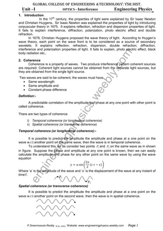
  • 1. GLOBAL COLLEGE OF ENGINEERING &TECHNOLOGY: YSR DIST. Unit –I OPTICS - Interference Engineering Physics 1. Introduction In the 17th century, the properties of light were explained by Sir Isaac Newton and Christian Huygens. Sir Isaac Newton was explained the properties of light by introducing corpuscular theory in 1675. It explains reflection, refraction and dispersion properties of light. It fails to explain interference, diffraction, polarization, photo electric effect and double refraction. In 1679, Christian Huygens proposed the wave theory of light. According to Huygen’s wave theory, each point on the wave front is to be considered as a source of secondary wavelets. It explains reflection, refraction, dispersion, double refraction, diffraction, interference and polarization properties of light. It fails to explain, photo electric effect, black m body radiation etc,. 2. Coherence .co Coherence is a property of waves. Two produce interference pattern coherent sources are required. Coherent light sources cannot be obtained from the separate light sources, but they are obtained from the single light source. bly Two waves are said to be coherent, the waves must have • Same wavelength • Same amplitude and ee • Constant phase difference s.w Definition:- A predictable correlation of the amplitude and phase at any one point with other point is called coherence. sic There are two types of coherence i) Temporal coherence (or longitudinal coherence) hy ii) Spatial coherence (or transverse coherence) Temporal coherence (or longitudinal coherence):- gp It is possible to predict the amplitude the amplitude and phase at a one point on the in wave w.r.t another point on the same wave, then the wave is in temporal coherence. To understand this, let us consider two points P1 and P2 on the same wave as in shown er in figure. Suppose the phase and amplitude at any one point is known, then we can easily calculate the amplitude and phase for any other point on the same wave by using the wave e equation 2ߨ ‫ ݕ‬ൌ ܽ sin ቆ ሺܿ ‫ ݐ‬െ ‫ݔ‬ሻቇ gin ߣ Where ‘a’ is the amplitude of the wave and ‘x’ is the displacement of the wave at any instant of time‘t’. en P1 P2 Spatial coherence (or transverse coherence) It is possible to predict the amplitude the amplitude and phase at a one point on the wave w.r.t another point on the second wave, then the wave is in spatial coherence. P.Sreenivasula Reddy M.Sc, (PhD) Website: www.engineeringphysics.weebly.com Page 1
  • 2. Independent sources are not coherent Two independent sources of light with same power can never be treated as coherent sources; even it emits same wavelength and same amplitude waves. Generally the light is emitted from the source through spontaneous emission process. But the waves emitted trough spontaneous emission process is in out of phase. So two waves generated by two light sources are always in out of coherence. Even the waves are emitted from the different parts of the lamp, no longer they are coherent. 3. Principle of superposition of waves Definition:- Principle of superposition of waves states that, the resultant displacement of two or more waves traveling simultaneously in a medium at any point is equal to the algebraic sum of the displacements due to individual waves. m To understand this concept, Let us consider two waves traveling simultaneously in the .co medium. Let ܻଵ and ܻଶ are the displacements of first and second waves at any point in the absence of other. According to principle of superposition, the resultant displacement ሺܻሻ of two waves bly can be written as ܻ ൌ ܻଵ േ ܻଶ ee Wave 1 + = s.w Wave 2 Let two waves are in phase, their resultant amplitude is ܻ ൌ ܻଵ ൅ ܻଶ sic Two waves are in opposite phase, their resultant amplitude is ܻ ൌ ܻଵ ~ ܻଶ hy Wave 1 gp + = Wave 2 in er 4. Young’s double slit experiment The first experimental evidence of interference pattern was given by Thomas Young In e 1801. He explained the interference pattern based on the wave nature of light. gin Experimental setup: His experimental arrangement is shown in figure. He passed the sun light through a narrow pin hole S on a opaque surface and then through closely spaced pin holes S1 and S2 in another opaque surface. A screen XY was arranged in front of the pin holes S1 and S2. He en observed few coloured bright and dark bands on the screen. Now a day, the pin holes are replaced by slits and sun light is replaced by monochromatic light. X S1 S2 S Screen Y
  • 3. GLOBAL COLLEGE OF ENGINEERING &TECHNOLOGY: YSR DIST. Unit –I OPTICS - Interference Engineering Physics Explanation of wave theory When sun light is passes through pin hole S, spherical waves are spread out. According to Huygen’s wave theory, each point on the wave front is to be considered as a source of secondary wavelets. Hence spherical waves also spread out from pin holes S1 and S2. The radii of the wave fronts increase as they move away from S1 and S2 and hence superimpose on each other. In the above figure, continuous circular arcs represent the wave crests while dotted circular arcs represent the troughs of each wave. A crest fall on the other crest constructive interference will occurs and their resultant amplitude is equal to the sum of the amplitudes individual waves. ܻ ൌ ܻଵ ൅ ܻଶ m A crest fall on the other trough destructive interference will occurs and their resultant .co amplitude is equal to the difference of the amplitudes of individual waves. ܻ ൌ ܻଵ െ ܻଶ Thus a number of dark and bright bands having equal width is observed on the screen. bly 5. Interference of light The best evidence for the wave nature of light is interference phenomenon. This was ee experimentally demonstrated by Thomas Young in 180, through double slit experiment. Due to interference, we will observe many observations in our day today life, such as multiple s.w colours on soap bubbles as well as on oil film when viewed under sun light. Interference concept is explained on the basis of superposition of wave’s concept. When two light waves superimpose, then the resultant amplitude or intensity in sic the region of superposition is different than the amplitude of individual waves. Definition:- hy The modification in the distribution of intensity in the region of superposition is known as interference. gp In case of interference pattern we observe two cases • Constructive interference in • Destructive interference er Constructive interference e The waves are reaching at a point are in phase constructive interference occurs In constructive interference, the resultant amplitude is always equal to the sum of the gin amplitudes of two individual waves. Condition en The path difference between the two waves is equal to the integral multiple of wave length ሺߣሻ the constructive interference occurs. ‫ ݁ܿ݊݁ݎ݂݁݅݀ ݄ݐܽ݌‬ൌ ݊ߣ Where n = 0, 1, 2, 3, 4 … Wave 1 + = Wave 2 P.Sreenivasula Reddy M.Sc, (PhD) Website: www.engineeringphysics.weebly.com Page 3
  • 4. Destructive interference The waves are reaching at a point are in out of phase desstructive interference occurs In Destructive interference, the resultant amplitude is always equal to the difference of the amplitudes of two individual waves. Condition The path difference between the two waves is equal to the odd integral multiple of λ/2 destructive interference occurs ሺ2݊ െ 1ሻߣ ‫ ݁ܿ݊݁ݎ݂݁݅݀ ݄ݐܽ݌‬ൌ Where n ൌ 1, 2, 3, 4 … ‫ݎ݋‬ 2 ሺଶ௡ାଵሻఒ ‫ ݁ܿ݊݁ݎ݂݁݅݀ ݄ݐܽ݌‬ൌ Where n ൌ 0, 1, 2, 3, 4 … ଶ m Wave 1 + .co = Wave 2 bly 6. Types of interference:- For the formation of interference pattern, two coherent light sources are required. To ee get two coherent sources form a single light source, two techniques are used. They are 1. Division of wave front 2. Division of amplitude s.w Division of wave front The wave front from a single light source is divided into two parts using the phenomenon of reflection, refraction or diffraction. Young’s double slit experiment is belongs sic to this class of interference. Division of amplitude The amplitude of a single light beam is divided into two parts by parallel reflection or hy refraction. Newton’s ring experiment, Michelson’s interferometer is belongs to this class of interference. gp 7. Conditions for interference in 1) Two light sources of emitting light waves should be coherent. 2) Two sources must emit continuous light waves of same wavelengths or frequency. er 3) The separation between the two sources should be small. 4) The distance between the two sources and the screen should be large. 5) To view interference fringes, the background should be dark. e 6) The amplitude of light waves should be equal or nearly equal. gin 7) The sources should be narrow. 8) The sources should be monochromatic. 8. Interference in thin films by reflection en Principle:- The formation of colours in thin films can explained as due to the phenomenon of interference. In this example, the formation of interference pattern is by the division of amplitude. . Consider a thin film of uniform thickness ’‫ ’ݐ‬and refractive index ‘µ’. Let a monochromatic light ray AB is incident is on the upper surface of the film with an angle ‘i’. This ray is partially reflected along BC and the remaining part is refracted along BD with an angle ‘r’. The refracted ray BD is reflected into DE from the lower surface of the film and it emerges through the film in the form of light ray EF. The two light rays BC and EF are parallel and superimpose and produce interference. The intensity of interference fringe depends up on the path difference between the ray 1 and ray 2.
  • 5. GLOBAL COLLEGE OF ENGINEERING &TECHNOLOGY: YSR DIST. Unit –I OPTICS - Interference Engineering Physics Ray 1 Ray 2 m .co bly To find out the path difference between the light rays (1) and (2), draw one ee normal DG to BE and from point E to BC. From point E and H onwards the two light rays 1 and 2 travels equal distances. By the time the light ray 1 travels from B to H, the s.w transmitted ray has to travel from B to C and D to E. The path difference between the light rays (1) and (2) is ‫ ݁ܿ݊݁ݎ݂݂݁݅݀ ݄ݐܽ݌‬ൌ ߤሺ‫ ܦܤ‬൅ ‫ܧܦ‬ሻ ݅݊ ݂݈݅݉ െ ‫ݎ݅ܽ ݊݅ ܪܤ‬ (1) sic ஽ீ ௧ From ∆‫ܩܦܤ‬ cos ‫ ݎ‬ൌ ൌ ஻஽ ஻஽ ‫ݐ‬ hy ‫ ܦܤ‬ൌ cos ‫ݎ‬ gp ஽ீ ௧ Similarly from ∆‫ܩܧܦ‬ cos ‫ ݎ‬ൌ ൌ ஽ா ஽ா ‫ݐ‬ in ‫ ܧܦ‬ൌ cos ‫ݎ‬ er ௧ ‫ ܦܤ ׵‬ൌ ‫ ܧܦ‬ൌ (2) ௖௢௦ ௥ e ஻ு ஻ு ∆‫ܪܧܤ‬ sin ݅ ൌ ൌ ஻ீାீா gin From ஻ா ‫ ܪܤ ׵‬ൌ ሺ‫ ܩܤ‬൅ ‫ܧܩ‬ሻ. sin ݅ From ∆‫ܩܧܦ∆ ݀݊ܽ ܩܦܤ‬ ‫ ܩܤ‬ൌ ‫ ܧܩ‬ൌ ‫ ݐ‬tan ‫ݎ‬ en ‫ ܪܤ‬ൌ ሺ2‫ ݐ‬tan ‫ݎ‬ሻ. sin ݅ From Snell’s law at point B sin ݅ ൌ ߤ sin ‫ݎ‬ ‫ ܪܤ ׵‬ൌ 2ߤ‫ ݐ‬tan ‫ . ݎ‬sin ‫ݎ‬ (3) Substituting the equations (2) and (3) in equation (1), we get ଶఓ௧ ܲܽ‫ ݁ܿ݊݁ݎ݂݂݁݅݀ ݄ݐ‬ൌ ୡ୭ୱ ௥ െ 2ߤ‫ ݐ‬tan ‫ . ݎ‬sin ‫ݎ‬ P.Sreenivasula Reddy M.Sc, (PhD) Website: www.engineeringphysics.weebly.com Page 5
  • 6. 2ߤ‫ݐ‬ sin ଶ ‫ݎ‬ ൌ െ 2ߤ‫.ݐ‬ cos ‫ݎ‬ cos ‫ݎ‬ 2ߤ‫ݐ‬ ൌ ሺ1 െ sin ଶ ‫ݎ‬ሻ cos ‫ݎ‬ 2ߤ‫ݐ‬ ൌ ܿ‫ ݏ݋‬ଶ ‫ݎ‬ cos ‫ݎ‬ =2ߤ‫ ݐ‬cos ‫ݎ‬ At point B the light ray (1) is reflected at the surface of thin film (denser medium). So the light ray (1) undergoes a phase change π or an additional path difference λ/2. ఒ Total path difference ൌ 2ߤ‫ ݐ‬cos ‫ ݎ‬െ ଶ Constructive interference (or Bright fridge) m General condition; ‫ ݁ܿ݊݁ݎ݂݂݄݁݅݀ݐܽ݌‬ൌ ݊ߣ ߣ 2ߤ‫ ݐ‬cos ‫ ݎ‬െ ൌ ݊ߣ .co 2 ߣ 2ߤ‫ ݐ‬cos ‫ ݎ‬ൌ ݊ߣ ൅ 2 bly ሺ2݊ ൅ 1ሻߣ 2ߤ‫ ݐ‬cos ‫ ݎ‬ൌ 2 ee Destructive interference (or Dark fridge) ఒ General condition: ‫ ݁ܿ݊݁ݎ݂݂݄݁݅݀ݐܽ݌‬ൌ ሺ2݊ ൅ 1ሻ ଶ s.w ߣ ሺ2݊ െ 1ሻߣ 2ߤ‫ ݐ‬cos ‫ ݎ‬െ ൌ 2 2 2ߤ‫ ݐ‬cos ‫ ݎ‬ൌ ݊ߣ sic 9. Newton’s rings hy Principle:- The formation of Newton’s rings can explained as due to the phenomenon of gp interference. In this example, the formation of interference pattern is obtained by the division of amplitude. in Experimental arrangement er The experimental arrangement of Newton’s rings is shown in figure. e The Plano -convex lens (L) of large gin radius of curvature is placed with its M convex surface on the glass plate (P). The lens touches the glass plate at en O. A monochromatic light is allowed to fall normally on the lens with the help of glass plate M kept at 450 to the incident monochromatic light. A part of light is reflected by the curved surface of the lens ‘L’ and a part of light is transmitted is partly O reflected back by the upper surface of the plane glass plate P as shown in figure. These reflected rays interfere and give rise to an interference pattern in the form of circular fringes. These rings are seen through microscope.
  • 7. GLOBAL COLLEGE OF ENGINEERING &TECHNOLOGY: YSR DIST. Unit –I OPTICS - Interference Engineering Physics Explanation of formation of Newton’s rings Newton’s rings are formed due to the interference between the light rays reflected from the lower surface of the lens and the upper surface of the glass plate (or top and bottom surfaces of the air film). Let R be the radius of curvature of the lens and ‫ ݐ‬be the thickness of the air film at point P. At point P a part of the incident monochromatic light is reflected from the bottom surface of the glass plate without phase change. The other part of the light is refracted from the upper surface of glass plate with additional phase change of π or path difference λ/2. The path difference between the two rays is ߣ m 2ߤ‫ ݐ‬cos ‫ ݎ‬൅ 2 For air film ߤ ൌ 1 and for normal incidence ‫ ݎ‬ൌ 0, so .co ఒ The path difference ൌ 2‫ ݐ‬൅ ଶ bly Constructive interference (or Bright fridge) General condition: ‫ ݁ܿ݊݁ݎ݂݂݄݁݅݀ݐܽ݌‬ൌ ݊ߣ ߣ 2‫ ݐ‬൅ ൌ ݊ߣ 2 ee ߣ 2‫ ݐ‬ൌ ሺ2݊ െ 1ሻ 2 Where ݊ ൌ 0, 1, 2, … … … .. s.w Destructive interference (or Dark fridge) ఒ General condition: ‫ ݁ܿ݊݁ݎ݂݂݄݁݅݀ݐܽ݌‬ൌ ሺ2݊ ൅ 1ሻ ଶ sic ߣ ߣ 2‫ ݐ‬൅ ൌ ሺ2݊ ൅ 1ሻ 2 2 hy 2‫ ݐ‬ൌ ݊ ߣ Where ݊ ൌ 0, 1, 2, … … … .. gp ఒ At the point of contact ‫ ݐ‬ൌ 0, path difference is ଶ i.e., the reflected and incidence light are out in of phase and destructive interference occur. So the center fringe is always dark. Theory of Newton’s rings er To find the diameters of a dark and bright fringes construct a circle with the radius of curvature R of a lens L and let us choose a point P at a distance ‘r’ from the center of lens and e ‫ ݐ‬be the thickness of air film at point ܲ. gin From the property of a circle ܰܲ. ܰ‫ ܤ‬ൌ ܱܰ. ܰ‫ܦ‬ ‫ ݎ .ݎ‬ൌ ܶ. ሺ2‫ ݎ‬െ ‫ݐ‬ሻ ‫ ݎ‬ଶ ൌ 2ܴ‫ ݐ‬െ ‫ ݐ‬ଶ en If t is small ‫ ݐ‬ଶ is negligible. ‫ ݎ‬ଶ ൌ 2ܴ‫ݐ‬ ‫ݎ‬ଶ r r ‫ݐ‬ൌ 2ܴ Bright rings ఒ For bright ring, the condition is 2‫ ݐ‬ൌ ሺ2݊ െ 1ሻ ଶ 2 ‫ݎ‬ଶ ߣ ൌ ሺ2݊ െ 1ሻ 2ܴ 2 ሺ2݊ െ 1ሻߣܴ ‫ݎ‬ଶ ൌ 2 P.Sreenivasula Reddy M.Sc, (PhD) Website: www.engineeringphysics.weebly.com Page 7
  • 8. By replacing r by D/2 the diameter of the bright ring is ‫ܦ‬ଶ ሺ2݊ െ 1ሻߣܴ ൌ 4 2 ‫ܦ‬ଶ ൌ 2ሺ2݊ െ 1ሻߣܴ ‫ ܦ‬ൌ ඥ2ሺ2݊ െ 1ሻߣܴ ‫ ܦ‬ൌ ඥሺ2݊ െ 1ሻ√2ߣܴ ‫ ן ܦ‬ඥሺ2݊ െ 1ሻ ‫ݎܾ݁݉ݑ݊ ݈ܽݎݑݐܽ݊ ݀݀݋√ ן ܦ‬ Dark rings m For dark rings, the condition is 2‫ ݐ‬ൌ ݊ ߣ .co 2 ‫ݎ‬ଶ ൌ݊ߣ 2ܴ bly ‫ ݎ‬ଶ ൌ ݊ ߣܴ By replacing r by D/2 the diameter of the nth dark ring is ee ‫ܦ‬ଶ ൌ ݊ ߣܴ 4 s.w ‫ ܦ‬ൌ √4݊ ߣܴ ‫ ܦ‬ൌ 2√݊ ߣܴ ‫݊√ ן ܦ‬ sic ‫ݎܾ݁݉ݑ݊ ݈ܽݎݑݐܽ݊√ ן ܦ‬ hy Note: suppose a liquid is taken in between the lens and glass plate having refractive index ߤ, then the diameter of the dark nth dark ring can be written as gp √4݊ ߣܴ ‫ܦ‬ൌ ߤ in 10. Determination of wave length of sodium light using Newton’s rings er By forming Newton’s rings and measuring the radii of the rings formed, we can e calculate the wavelength of the light used if the radius of curvature of the lens is known. Let R be the radius of curvature of the lens and ߣ is the wavelength of the light used. gin So the diameter of the nth dark ring can be written as ‫ܦ‬௡ ଶ ൌ 4 ݊ ߣ ܴ (1) en Similarly the diameter of the (n+m)th dark ring is ‫ܦ‬௡ା௠ ଶ ൌ 4 ሺ݊ ൅ ݉ሻ ߣ ܴ (2) Subtracting equation (1) from (2) we get ‫ܦ‬௡ା௠ ଶ െ ‫ܦ‬௡ ଶ ൌ 4 ሺ݊ ൅ ݉ሻߣ ܴ െ 4 ݊ ߣ ܴ ‫ܦ‬௡ା௠ ଶ െ ‫ܦ‬௡ ଶ ൌ 4 ݉ ߣ ܴ ‫ܦ‬௡ା௠ ଶ െ ‫ܦ‬௡ ଶ ߣൌ 4ܴ݉ Using the above relation wavelength can be calculated
  • 9. GLOBAL COLLEGE OF ENGINEERING &TECHNOLOGY: YSR DIST. Unit –I OPTICS - Interference Engineering Physics 11. Determination of refractive index of a liquid using Newton’s rings By forming Newton’s rings and measuring the diameter of the rings formed, we can calculate the refractive index of the liquid. In air film, the diameter of the nth and mth dark rings are ‫ܦ‬௡ and ‫ܦ‬௠ are measured with the help of travelling microscope. The diameter of the nth dark ring is ‫ܦ‬௡ ଶ ൌ 4 ݊ ߣ ܴ m (1) The diameter of the mth dark ring is .co ‫ܦ‬௠ ଶ ൌ 4 ݉ߣ ܴ (2) So ‫ܦ‬௠ ଶ െ ‫ܦ‬௡ ଶ ൌ 4 ݉ߣ ܴ െ 4 ݊ ߣ ܴ bly ‫ܦ‬௠ ଶ െ ‫ܦ‬௡ ଶ ൌ 4 ሺ݉ െ ݊ሻ ߣ ܴ (3) The Newton’s rings setup is taken in a liquid. Now the air film is replaced by liquid film. In liquid film, the diameters of the same nth and mth dark rings are ‫ ′ܦ‬௡ and ‫ ′ܦ‬௠ are measured ee with the help of travelling microscope. ଶ ସ௡ఒோ ‫ ′ܦ‬௡ ൌ s.w and ఓ ଶ 4݉ߣܴ ‫′ܦ‬௠ ൌ ߤ sic ଶ ଶ ସ ሺ௠ି௡ሻ ఒ ோ So ‫ ′ܦ‬௠ െ ‫ ′ܦ‬௡ ൌ (4) ఓ hy Dividing equation (3) by (4) ‫ܦ‬௠ ଶ െ ‫ܦ‬௡ ଶ 4 ሺ݉ െ ݊ሻ ߣ ܴ ൌ ଶ ଶ 4 ሺ݉ െ ݊ሻ ߣ ܴ gp ‫′ܦ‬௠ െ ‫ ′ܦ‬௡ ߤ ‫ܦ‬௠ ଶ െ ‫ܦ‬௡ ଶ ൌߤ in ଶ ଶ ‫ ′ܦ‬௠ െ ‫ ′ܦ‬௡ er Using the above relation ߤ can be calculated. e gin en P.Sreenivasula Reddy M.Sc, (PhD) Website: www.engineeringphysics.weebly.com Page 9
  • 10.         en gin ee rin gph ys ics .w ee bly .co m
  • 11. GLOBAL COLLEGE OF ENGINEERING &TECHNOLOGY: YSR DIST. Unit –I OPTICS - Diffraction Engineering Physics Introduction The wave nature of light is first confirmed by the phenomenon of interference. Further it is confirmed by the phenomenon of diffraction. The word ‘diffraction’ is derived from the Latin word diffractus which means break to piece. When the light waves encounter an obstacle, they bend round the edges of the obstacle. The bending is predominant when the size of the obstacle is comparable with the wavelength of light. The bending of light m waves around the edges of an obstacle is diffraction. It was first observed by Gremaldy. .co 1. Diffraction Definition:- When the light falls on the obstacle whose size is comparable with the wavelength of bly light then the light bends around the obstacle and enters in the geometrical shadow. This bending of light is called diffraction. ee When the light is incident on an obstacle AB, their corresponding shadow is completely dark on the screen. Suppose the width of the slit is comparable to the .w wavelength of light, then the shadow consists of bright and dark fringes. These fringes are formed due to the superposition of bended waves around the corners of an obstacle. The amount of bending always depends on the size of the obstacle and wavelength of light used. ics ys g ph rin 2. Types of diffraction The diffraction phenomena are classified into two ways ee I. Fresnel diffraction II. Fraunhofer diffraction. gin Fresnel diffraction:- In this diffraction the source and screen are separated at finite distance. To study this en diffraction lenses are not used because the source and screen separated at finite distance. This diffraction can be studied in the direction of propagation of light. In this diffraction the incidence wave front must be spherical of cylindrical. Fraunhofer diffraction:- In this diffraction the source and screen are separated at infinite distance. To study this diffraction lenses are used because the source and screen separated at infinite distance. This diffraction can be studied in any direction. In this diffraction the incidence wave front must be plane. P.Sreenivasula Reddy M.Sc, (PhD) Website: www.engineeringphysics.weebly.com Page 1
  • 12. 3. Fraunhofer single slit diffraction:- Let us consider a slit AB of width ‘e’. Let a plane wavefront of monochromatic light of wavelength λ is incident on the slit AB. According to Huygens principle, every point on the wavefront is a source of secondary wavelets. Those secondary wavelets travelling normal to the slit are brought to focus at point P0 on the screen by using the lens. The secondary wavelets traveling at an angle θ with the normal are focused at point P1. m .co bly Intensity at point P1 depends up on the path difference between the wavelets A and B ee reaching to point P1. .w 2 2 sin ics Let the width of the slit is divided into ‘n’ equal parts and the amplitude of the wave front each part is ‘a’. Then the phase difference between any two successive waves from these ys parts would be 1 1 2 sin ph Using the vector addition method, the resultant amplitude R is sin g 2 rin sin 2 1 2 sin . sin ee sin sin 2 1 2 sin sin sin sin gin 2 sin sin sin en sin sin sin sin Therefore resultant intensity
  • 13. GLOBAL COLLEGE OF ENGINEERING &TECHNOLOGY: YSR DIST. Unit –I OPTICS - Diffraction Engineering Physics Principal maximum:- The resultant amplitude R can be written as 3! 5! 7! 1 3! 5! 7! m 1 3! 5! 7! In the above expression for 0 values the resultant amplitude is maximum .co Then sin 0 bly sin 0 0 For 0 value the resultant intensity is maximum at P0 and is known as principal ee maximum. Minimum intensity positions .w Will be minimum when sin 0 1,2,3,4,5 … … .. sin ics sin ys So we obtain the minimum intensity positions on either side of the principal maxima for all values. ph Secondary maximum In between these minima secondary maxima positions are located. This can be obtained by differentiating the expression of w.r.t and equation to zero g sin 0 rin 2sin sin 0 ee 2sin cos sin · 0 gin In the above expression can never equal to zero, so Either sin 0 or cos sin 0 sin 0 gives the positions of minima. en The condition for getting the secondary maxima is cos sin 0 cos sin tan The values of satisfying the above equation are obtained graphically by plotting the curves and tan on the same graph. The plots of and tan is shown in figure. P.Sreenivasula Reddy M.Sc, (PhD) Website: www.engineeringphysics.weebly.com Page 3
  • 14. m From the graph intersecting points are 0, , , ………… .co From the above concepts the intensity distribution curve verses is shown in figure. bly ee .w ics ys ph 4. Fraunhofer double slit diffraction Let S1and S2 be the two slits equal width e and separated by a distance d. The g distance between the two slits is (e + d). A monochromatic light of wavelength λ is incident on the two slits. The diffracted light from these slits is focused on the screen by using a rin lens. The diffraction of a two slits is a combination of diffraction and interference. The wavelets travelling normal to the slit is focused at P0. The wavelets travelling at an angle θ ee with the incident light are focused at point P1. From Fraunhofer single slit experiment, the resultant amplitude is gin So the amplitude of each secondary wavelet travelling with an angle θ can be taken sin as . These two wavelets interference and meet at point P1 on the screen. en
  • 15. GLOBAL COLLEGE OF ENGINEERING &TECHNOLOGY: YSR DIST. Unit –I OPTICS - Diffraction Engineering Physics To find out the path difference between the two wavelets, let us draw a normal s1k to the wavelet S2. S S S From ∆S S k sin S S S sin 2 2 sin m By using vector addition method, we can calculate the resultant amplitude at point P1 2 cos .co sin sin sin sin 2 cos sin sin 2 2 cos bly sin 2 1 cos ee sin 2 1 2 cos 1 sin 2 2 cos 4 sin .w cos ics sin 4 cos sin ys sin ph 4 cos The resultant intensity 4 cos g From the above equation, it is clear that the resultant intensity is a product of two factors i.e., rin 1. represents the diffraction pattern due to a single slit. 2. cos represents the interference pattern due to wavelets from double slit. ee Diffraction effect In diffraction pattern the variation of w.r.t as shown in figure. gin en P.Sreenivasula Reddy M.Sc, (PhD) Website: www.engineeringphysics.weebly.com Page 5
  • 16. The diffraction pattern consists of central principal maxima for 0 value. The secondary maxima of decreasing intensity are present on either side of the central maxima for , , values. Between the secondary maxima the minima values are present for , 2 , values. Interference effect In interference pattern the variation of cos w.r.t as shown in figure. m .co bly ee cos represents the interference pattern. Interference maximum will occur for cos 1 .w 0, 1, 2, 3, 4 … … … , 2 , 3 , 4 ……… ics sin sin ys Interference minima will occur for cos 0 ph 2 1 2 sin 2 1 2 g sin 2 1 rin 2 The resultant intensity variation due both interference and diffraction patterns is shown in figure. Due to interference the resultant minimum in not exactly equal to zero. ee gin en
  • 17. θ GLOBAL COLLEGE OF ENGINEERING &TECHNOLOGY: YSR DIST. Unit –I OPTICS - Diffraction Engineering Physics Construction of plane diffraction grating Or Construction of grating A set of large number of parallel slits of same width and separated by opaque spaces is known as diffraction grating. Fraunhofer used the first grating consisting of a large number of parallel wires placed side by side very closely at regular separation. Now the m gratings are constructed by ruling the equidistance parallel lines on a transparent material .co such as glass with fine diamond point. The ruled lines are opaque to light while the space between the two lines is transparent to light and act as a slit. bly Let ‘e’ be the width of line and‘d’ be the width of the slit. Then (e + d) is known as grating element. If N is the number of lines per inch on the grating then ee 1 2.54 . .w ics ys g ph rin ee Plane Diffraction grating ( or diffraction at N - slits) Let a plane wavefront of monochromatic light of wavelength λ is incident on the gin slits. Let ‘e’ be the width of line and ‘ ’ be the width of the slit. Then (e + d) is known as grating element. According to Huygens principle, every point on the wavefront is a source of secondary wavelets. The wavelets spread out to the right in all directions. Those en secondary wavelets travelling normal to the slit are brought to focus at point P0 on the screen by using the lens. . The wavelets travelling at an angle θ with the incident light are focused at point P1. P.Sreenivasula Reddy M.Sc, (PhD) Website: www.engineeringphysics.weebly.com Page 7
  • 18. sin The resultant amplitude due to diffraction of a single slit is , where sin . Let us assume that there are N slits in the grating. The path difference between the corresponding points is sin 2 . The resultant of amplitude R of the N amplitudes of is sin sin 1 sin m And intensity is .co sin sin . 2 sin bly In the above equation shows the intensity distribution due to a single slit diffraction and shows the combined intensity distribution due to interference at all ee the N slits. Principal Maxima: from equation 2, we know that the intensity would be maximum .w when sin 0, where 0, 2 , … . . and n= 0,1,2,3… Indeterminate ics To find out its value, L- Hospitals rule is applied sin sin cos ys lim lim lim sin sin cos ph Hence the resultant intensity is can be written as sin g rin So the maxima are obtained for sin or ee sin Minima: From equation 2 the resultant intensity is minimum for sin 0 but sin 0 gin sin en sin can be take integral values except 0, N, 2N,………..nN. For these values we bet maxima Secondary maxima: Between two adjacent principal maxima there are 1 minima and 2 other maxima called secondary maxima.b to get the position so secondary maxima, differentiate equation 2 w.r.t and then equate to zero.
  • 19. GLOBAL COLLEGE OF ENGINEERING &TECHNOLOGY: YSR DIST. Unit –I OPTICS - Diffraction Engineering Physics sin sin cos sin sin cos 2 . 0 sin 2 cos sin sin cos 0 or tan tan The roots of the above equation (other than , this corresponds to principal maxima) give the secondary maxima. m The variation of intensity due to the interference factor is shown in figure .co bly ee .w The variation of intensity due to the diffraction factor of is shown in figure ics ys g ph rin The variation of resultant intensity is shown in figure. ee gin en P.Sreenivasula Reddy M.Sc, (PhD) Website: www.engineeringphysics.weebly.com Page 9
  • 20. 5. Grating spectrum When white light is fall on the grating, the light gets diffracted through each slit. As a result of both interference and diffraction, diffraction pattern will occur. This pattern is known as grating spectrum or diffraction spectrum. m .co bly ee .w ics ys ph The condition for the principal maximum in grating spectrum is sin g Where is the grating element and is the order of spectrum. From the grating equation, we observe that rin 1. For a particular wavelength λ the angle of diffraction θ is different for principal maxima and for different orders. ee 2. For white light and for a particular order , the light of different wavelengths will be diffracted in different directions. 3. Angle of diffraction increases with wavelength. gin 4. In the spectrum violet is in the innermost position and red at the outermost position. 5. Most of the energy is distributed for zero order and the rest is distributed among the other orders. en 6. Spectrum different orders are situated symmetrically on both sides of zero order. 7. Sharpness of maxima increases with increasing of number of lines in the grating. 8. The colour of central maxima is same as the incident light. 9. The condition for finding the maximum number of orders formed by the grating is
  • 21. GLOBAL COLLEGE OF ENGINEERING &TECHNOLOGY: YSR DIST. Unit –I OPTICS - polarisation Engineering Physics Introduction From the previous chapter’s interference and diffraction, we can understand that the light is exhibiting wave nature. But these phenomenon don’t explain the character of these wave motion i.e., whether it is longitudinal or transverse. In longitudinal waves, the particles of the medium move to and fro in the direction of propagation of the wave as in case of sound waves. In transverse waves, the particles of the medium vibrate up and down perpendicular to the direction of propagation of wave m as ripples on a water surface. .co 1. Polarization Light is electromagnetic in nature, it consists of oscillating electric and magnetic fields of vectors. They are perpendicular to each other and perpendicular to the propagation of light. In light, the electric field direction is always changes in random ways. So the unpolarized or bly ordinary light is represented as shown in figure. ee If the direction of electric field vector is confined to one fixed direction, that light beam is .w called linearly polarized or plane polarized light. So the plane polarized light is represented as shown in figure ics ys Definition: ph The process of restricting the vibration of electric field vector is called polarization. 2. Plane of polarization and plane of vibration g Plane of vibration: - rin The plane which contains the vibrations of polarized is known as plan of vibration. Plane of vibration:- ee The plane perpendicular to the plane of vibration is known as plane of polarization. When an unpolarized light is incident on the polarizer, the emergent light beam always has vibrations parallel to the optic axis. gin en In the figure the plane parallel to the optic axis of the polarizer and containing the vibrations of polarized light and hence it is known as plane of vibration the plane is perpendicular to the plane of vibration and hence it is known as plane of polarization. P.Sreenivasula Reddy M.Sc, (PhD) Page 1 of 9
  • 22. 3. Definitions: Blunt corners:- If any corner contain all obtuse angles (is an angle between 90 and 180 degrees), which is called blunt corner. Optic axis: - A line joining the two blunt corners is known as optic axis of the crystal. An optic axis is not an axis, but it is a direction of a crystal. Any line parallel to the optic is also known as optic axis. Uniaxial crystal: - If any crystal having only one optic axis is known as uniaxial crystal. Examples: - calcite, quartz. m Biaxial crystal: - .co If any crystal having two optic axes is known as biaxial crystal. Examples: -borax, mica. bly Principal section: - A plane containing the optic axis and perpendicular to two opposite faces of the crystal is known as the principal section of the crystal. ee Principal planes: - The plane having the optic axis and ordinary ray of the crystal is known as principal plane of .w the ordinary ray. The plane having the optic axis and extraordinary ray of the crystal is known as principal plane of the extraordinary ray. ics 4. Production of polarized light For the production of plane polarized light different methods are followed, they are ys a) Polarization by reflection b) Polarization by transmission c) Polarization by absorption ph d) Polarization by double refraction g a) Polarization by reflection rin When the unpolarized light is fall on the smooth surface such as glass or water surface, the reflected light is partially plane polarized. The degree of polarization changes with the angle ee of incidence. For a particular angle of incidence the reflected light was completely polarized transmitted light ray is partially plane polarized. The vibration of the reflected light is gin perpendicular to the plane of incidence. The polarizing angle for glass is 57.50 At which angle of incidence the reflected ray is completely plane polarized, that angle is called polarizing angle or angle of polarization. en
  • 23. GLOBAL COLLEGE OF ENGINEERING &TECHNOLOGY: YSR DIST. Unit –I OPTICS - polarisation Engineering Physics b) Polarization by transmission When the unpolarized light incident on smooth surface at polarizing angle the reflected light is plane polarized and the transmitted light ray is partially plane polarized. When the unpolarized light incident on the pile of plates at polarizing angle, the transmitted light ray is purely plane polarized. The polarizing angle for glass is 57.50. The vibration of the transmitted light is parallel to the plane of incidence. m .co bly ee c) Polarization by absorption When un polarized light is passing through the tourmaline ( , , , it is split into horizontal and vertical components. The horizontal components are completely absorbed by the .w crystal and the vertical component comes out. The light coming from the crystal is linearly polarized. ics ys ph d) Double refraction: - When an unpolarized light is passes through a calcite crystal, it is split up into two plane g polarized lights. This phenomenon is known as double refraction. rin ee gin In which, one ray obeys the laws of refraction and has vibrations perpendicular to the principal section is known as ordinary ray. The other ray does not obey the laws of refraction and has en vibrations parallel to the principal section is known as extraordinary ray. The refractive index of ordinary and extraordinary rays for calcite crystal is sin sin          sin sin In calcite crystal the velocity light for O- ray inside the crystal is less than the E- ray. The refractive index of O-ray is same for all angle of incidence and hence it is represented by spherical wave front. The refractive index of E-ray is always varies with the angle of incidence and hence it is represented by ellipsoidal wave front. But both rays are travel with same velocity along the optic axis of the calcite crystal. P.Sreenivasula Reddy M.Sc, (PhD) Page 3 of 9
  • 24. 5. Polarization of light waves Let us consider an unpolarized light is passed through the tourmaline crystal as shown in figure. Even when we are rotating the tourmaline crystal by taking the incident ray as an axis, there is no intensity variation in the emergent beam. The tourmaline crystal only allows the vibrations of light that are parallel to the axis of the crystal, and it does not allow the other vibrations. So the emergent beam from the tourmaline crystal is a polarized light. So the first tourmaline crystal is called polarizer. m .co bly If the second tourmaline crystal is rotated by taking the incident ray as an axis, the intensity of emergent beam from the second tourmaline crystal has two times minimum intensity and two times maximum intensity is observed within one complete rotation. When the second tourmaline crystal is ee parallel to the first one the emergent beam from the second crystal is maximum. When the second tourmaline crystal is perpendicular to the first one the emergent beam from the second crystal is minimum. Therefore the second crystal is called analyzer. .w So this property of light of rays confirms the transverse nature of light rays. 6. Nicol prism ics Nicol prism is an optical device made from calcite and is used to produce and analyze plane polarized light. It was invented by Nicol in 1828 and is known as Nicol prism. ys Principle:- Nicol prism is worked on the principle of double refraction exhibited by calcite crystal. Construction:- ph Nicol prism is constructed by using calcite crystal. Its length and breadth dimensions are in the ratio 3:1. Consider a calcite crystal, in which is the principal section and B and D are blunt g corners. The angles of the principal section are 710 and 1090. The angle of the principal section is rin reduced from 710 to 680 by grinding the faces of AB and CD. After grinding the new principal section is The crystal is cut into two pieces perpendicular to the principal section along  . The two ee cut surfaces are highly polished into optical flat and joined together by means of Canada balsam. The refractive index of Nicol prism for sodium wave length 5893 and the refractive indices of gin ordinary ray, extraordinary ray and Canada balsam are 1.658, 1.46 and 1.55 respectively. The two faces of the Nicol prism is kept open, while the two sides are blackened to absorb the totally internally reflected rays. en   B C Canada balsam cement 68 71 A D
  • 25. GLOBAL COLLEGE OF ENGINEERING &TECHNOLOGY: YSR DIST. Unit –I OPTICS - polarisation Engineering Physics Working of Nicol prism When an unpolarized light is passes through a calcite crystal, it is split up into two beams, namely, ordinary and extraordinary rays. m E ray .co When the ordinary ray passing through the calcite, the Canada balsam layer acts as a rarer medium. bly Therefore the ordinary ray is travelling from denser (calcite) to rarer (Canada balsam) medium. For ordinary ray, the angle of incidence at the interface of calcite and Canada balsam is greater than the critical angle, it undergoes total internal reflection. ee The critical angle for the ordinary ray is 1.55 sin 69.2 .w 1.658 The angle of the principal section is greater than the critical angle, so the upper and lower surfaces of the Nicol prism are grounded from 710 to 680. For the extraordinary ray the Canada balsam is acts as ics a dense medium. Hence it travels in a straight line and emerges out from the Nicol prism. The emergent beam is plane polarized light. ys 7. Plane polarized light by Nicol prism. A Nicol prism is used to produce and analyze plane polarized light. When an unpolarized ph light is passed through a Nicol prism, it is split up into ordinary and extraordinary rays. The ordinary ray is cut of when it is passing from calcite to Canada balsam layer. The extraordinary ray is passed g through the Nicol prism. rin ee gin en If the second Nicol prism is rotated by taking the incident ray as an axis, the intensity of emergent beam from the second Nicol prism has two times minimum intensity and two times maximum intensity is observed within one complete rotation. The first Nicol prism is known as polarizer and the second Nicol prism is known as analyzer. Thus a Nicol prism can be used as a polarizer as well as analyzer. P.Sreenivasula Reddy M.Sc, (PhD) Page 5 of 9
  • 26. 8. Limitations of Nicol prism 1. The Nicol prism acts as a polarizer only for the light rays having slightly convergent and slightly divergent beam. 2. The Nicol prism does not acts as a polarizer for the light rays having highly convergent and highly divergent beam 3. If the incident divergent beam is making larger angle with the front face, the extraordinary ray will become parallel to the optics axis of the crystal. Extraordinary ray also totally internally reflected by the Canada balsam layer. Therefore no light emerges our from the Nicol prism. 4. If the incident convergent beam is making small angle with the front face, the ordinary makes less critical angle at the calcite and Canada balsam interface. Then the ordinary ray also emerges out m from the Nicol prism. 9. Quarter wave plate .co A wave plate is an optical device, is used to produce path difference or phase difference between the ordinary and extraordinary rays. It is made from the doubly refracting uniaxial crystals. Its faces are cut parallel to the direction of the optic axis. bly When the polarized light is incident on the calcite crystal, the light splits up into O-ray and E- ray. The thickness of the device is cut in such way it can produce the path difference 4 or phase difference 2 between the O-ray and E-ray is called quarter wave plate. ee Let be the thickness of the crystal. Let and be the refractive indices of E-ray and O- ray. Then the path difference between E-ray and O-ray is       For quarter wave plate path difference = 4   .w ics 4   4 ys For negative crystals   For positive crystals ph 10. Half wav e plate A wave plate is an optical device, is used to produce path difference or phase difference g between the ordinary and extraordinary rays. It is made from the doubly refracting uniaxial crystals. rin Its faces are cut parallel to the direction of the optic axis. When the plane polarized light is incident on the calcite crystal, the light splits up into O-ray and E- ee ray. When the refracting faces are cut parallel to the optic axis, O-ray and E-ray travels with different velocities along the same path. The thickness of the device is cut in such way it can produce the path difference 2 or path gin difference between the O-ray and E-ray is called half wave plate. Let be the thickness of the crystal. Let and be the refractive indices of E-ray and O-ray. Then the path difference between E-ray and O-ray is  en     For half wave plate path difference = 2   2   2 For negative crystals   For positive crystals
  • 27. GLOBAL COLLEGE OF ENGINEERING &TECHNOLOGY: YSR DIST. Unit –I OPTICS - polarisation Engineering Physics 11. Theory of circular and elliptical polarized lights A beam of plane polarized light is obtained by passing the unpolarized light through the Nicol prism. Let be the maximum amplitude of the incident light which makes an angle with the optic axis. When the plane polarized light is passes through a wave plate, it is split up into two ordinary and extraordinary rays. The amplitudes of ordinary and extraordinary rays are sin   and cos respectively. A sin m Q .co P A cos bly The ordinary and extraordinary rays travel with different velocities in the same direction, and ee hence a phase difference is introduced between these two rays. Let be the phase difference between the ordinary and extraordinary rays. The emergent beam from the wave plate can be represented as .w cos sin (1) sin sin (2) ics Taking cos and sin , the above equations can be written as  sin (3) ys  sin (4) Equations (3) and (4) can be written as ph  sin (5) g  sin (6) rin Equation (5) can be written as  sin cos    cos  sin (7) ee Substituting the value of  sin and  cos from equation (6) in equation (7) gin  cos   1   sin (8) Squaring equation (8), we get en  cos 2  cos   1   sin  cos 2  cos     sin   sin  cos   sin 2  cos     sin 2  cos     sin (9) P.Sreenivasula Reddy M.Sc, (PhD) Page 7 of 9
  • 28. Equation (9) is a general expression for an ellipse.   when 0,   sin 0 and  cos 1 Equation (9) becomes 2  0 0   m The above expression represents a straight line. Therefore the light is plane polarized.   when ,   sin 1 and  cos 0 .co Equation (9) becomes  1 bly This represents the equation of a ellipse. Thus the emergent light in this case will be elliptically polarized light.   when ,   sin 1,  cos 0 and ee  1 .w This represents the equation of a circle. Thus the emergent light in this case will be circularly ics polarized light 12. Differences between polarized light and unpolarized light ys Unpolarized light Polarized light ph When an unpolarized light is passed through the When a polarized light is passed through the rotating tourmaline crystal, no variation intensity rotating tourmaline crystal, variation in the of light is observed. intensity of light is observed. g The unpolarized light is symmetrical about the The polarized light is lack symmetry about the direction of propagation of light. direction of propagation light. rin In unpolarized light the vibrations are confined to In polarized light the vibrations are confined to any direction. one particular direction. ee The unpolarized light is specified as The polarized light is specified as gin en Differences between O-ray and E-ray O-ray E-ray The O-ray obeys the laws of refraction The E-ray does not obeys the laws of refraction The O-ray has vibrations perpendicular to the The E-ray has vibrations parallel to the principal principal section. section In negative crystal the velocity light for O- ray is In positive crystal the velocity light for E- ray is less than the E- ray less than the O- ray The refractive index of O-ray is same for all The refractive index of E-ray is always varies angle of incidence with the angle of incidence
  • 29. GLOB BAL COLLE EGE OF EN NGINEERI ING &TEC CHNOLOGY YSR DIS Y: ST. Unit –I – OPTICS - polarisat tion Engineer E ring Phys sics 13. A Analysis or detection of unknown p d f polarization n m .co bly ee .w ics ys g ph rin ee gin en P.Sr reenivasu Reddy ula M.Sc, (PhD) Page 9 of 9 e