opsahu advanced communication lab 6 sem.file r.k.r govt poly janjgir
•
1 like•167 views

advanced communication lab file 6sem.

Recommended
More Related Content
What's hot
What's hot (20)
Similar to opsahu advanced communication lab 6 sem.file r.k.r govt poly janjgir
Similar to opsahu advanced communication lab 6 sem.file r.k.r govt poly janjgir (20)
More from Government Engineering College, Raipur
More from Government Engineering College, Raipur (10)
Recently uploaded
Recently uploaded (20)
opsahu advanced communication lab 6 sem.file r.k.r govt poly janjgir
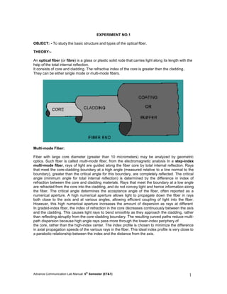
- 1. Advance Communication Lab Manual: 6th Semester (ET&T) 1 EXPERIMENT NO.1 OBJECT: - To study the basic structure and types of the optical fiber. THEORY:- An optical fiber (or fibre) is a glass or plastic solid rode that carries light along its length with the help of the total internal reflection. It consists of core and cladding. The refractive index of the core is greater then the cladding.. They can be either single mode or multi-mode fibers. Multi-mode Fiber: Fiber with large core diameter (greater than 10 micrometers) may be analyzed by geometric optics. Such fiber is called multi-mode fiber, from the electromagnetic analysis In a step-index multi-mode fiber, rays of light are guided along the fiber core by total internal reflection. Rays that meet the core-cladding boundary at a high angle (measured relative to a line normal to the boundary), greater than the critical angle for this boundary, are completely reflected. The critical angle (minimum angle for total internal reflection) is determined by the difference in index of refraction between the core and cladding materials. Rays that meet the boundary at a low angle are refracted from the core into the cladding, and do not convey light and hence information along the fiber. The critical angle determines the acceptance angle of the fiber, often reported as a numerical aperture. A high numerical aperture allows light to propagate down the fiber in rays both close to the axis and at various angles, allowing efficient coupling of light into the fiber. However, this high numerical aperture increases the amount of dispersion as rays at different In graded-index fiber, the index of refraction in the core decreases continuously between the axis and the cladding. This causes light rays to bend smoothly as they approach the cladding, rather than reflecting abruptly from the core-cladding boundary. The resulting curved paths reduce multi- path dispersion because high angle rays pass more through the lower-index periphery of the core, rather than the high-index center. The index profile is chosen to minimize the difference in axial propagation speeds of the various rays in the fiber. This ideal index profile is very close to a parabolic relationship between the index and the distance from the axis.
- 2. Advance Communication Lab Manual: 6th Semester (ET&T) 2 Single mode Fiber: The most common type of single-mode fiber has a core diameter of 8–10 micrometers and is designed for use in the near infrared. The mode structure depends on the wavelength of the light used, so that this fiber actually supports a small number of additional modes at visible wavelengths. Multi-mode fiber, by comparison, is manufactured with core diameters as small as 50 micrometers and as large as hundreds of micrometres. The normalized frequency V for this fiber should be less than the first zero of the Bessel function J 0 (approximately 2.405). Single mode fiber has the least dispersion and hence are used for longer distances. PROCEDURE AND OBSERVATION:- Connect the given optical fiber with the light source and observe the light patters and the diameter of the fiber. Result ………………………………………………………………………………………………………………… ………………………………………………………………………………………………………………… ………………………………………………………………………………………
- 3. Advance Communication Lab Manual: 6th Semester (ET&T) 3 EXPERIMENT NO.2 OBJECT: - To measure the numerical aperture (NA) of the different cables provided EQUIPMENT:- • Provided optical cables • Laser emitter • Measurement bench THEORY:- Numerical Aperture is defined as the light gathering capability of the fiber Mathematically given by: NA= Sin θ A Where: Sin θ = (D/2L) A • L is the distance between the cable end and the measurement bench L=20mm • D is the diameter of the acceptance cone PROCEDURE:- • Insert one end of the cable into the laser source (660nm)and other end into the measuring bench . • Activate the laser source • Evaluate the diameter of the lightened area • As we move from cable 3 to cable 5 the brightness of the light point decreases as it is the function of the core diameter and the light become focused at single point .
- 4. Advance Communication Lab Manual: 6th Semester (ET&T) 4 OBSERVATION:- (Diameter of each circle is 2 mm) Cable 3 (200/230) μm (step index multimode) D= …………… NA=………….. Cable 4 (62.5/125) μm (graded index multi mode) D= …………… NA=………….. Cable 5 (09/125) μm (step index single mode) RESULT:- It has been observed that as the diameter of the core decreases the NA also decreases as the light gathering capability is the function of core diameter. D= …………… NA=…………..
- 5. Advance Communication Lab Manual: 6th Semester (ET&T) 5 EXPERIMENT NO.3 OBJECT:- To measure the optical power emitted by the LED. EQUIPMENT:- • power supply psu or ps1 • Testing module MCM-40 • multimeter • optical power meter THEORY:- The commonest optical sources are light-emitting diodes(LED) and laser diodes (LD) . Both these diodes can be used to generate radiations at different wavelengths, corresponding to the windows where fibers show the minimum attenuation. The LED is a particular diode which emits light through process of recombination of the electron- hole pairs due to a forward bias of the junction The optical power emitted is a function of the st forward driving current .At present the LEDs in the 1 windows are made of gallium arsenide or of nd rd the ternary compound with aluminum (ALGaAs/GaAs), the LEDs in the 2 e 3 made of indium gallium-arsenide-phosphide (InGaAsP/InP). The most significant parameters of LED are: • Output wave length • Output spectral width windows are • Output optical power: it ranges in some tens of μW, and depends on the forward driving current. • Frequency response. PROCEDURE:- Optical power emitted by LEDs • Power the module • Disconnect the jumper j11-j13 and connect the jumper j12b, so that the circuit can be arranged as shown in fig 1. this configuration includes the LED at 660nm, forward polarized through the bias trimmer (p4)
- 6. Advance Communication Lab Manual: 6th Semester (ET&T) 6 • Measure the voltage v 10 across the resistor of 10Ω connected in the series of LED (between TP15 and ground). the forward current i f formula: crossing the Led in expressed by the following I =v F 10 /10 [v 10 in mv, I inma] f • observe the intensity of the light emitted by the LED • Power increase as current increase. Characteristic Curves of LEDs • Disconnect the jumper j11-j12 and connect the jumper j13b, so that circuit can be arranged as shown in figure2. this configuration includes the LED at 820nm, forward polarized through the bias trimmer (p4) and the voltageV10 across f the resistor of 10Ω connected in the series of LED (between TP15 and ground). the forward current i crossing the Led in expressed by the following formula: f I =v F 10 /10 [v 10 in mv, I inma] f • Connect the LED to optical power meter through cable3(200/230) • Vary the BIAS trimmer P4 and measure V V I and optical power P f , 10 , F out • Plot the curve for the optical power of LED versus I F and of I F versus V F • Change cable 3 with cable 4(50/125) and then with cable 5 (10/125) and observe the reading. of optical power OBSERVATION: RESULT:- • Characteristic curves of LED source is observed. • By changing the fiber optic cables it was observed that the optical power decreases as the Numerical Aperture of the cable decreases
- 7. Advance Communication Lab Manual: 6th Semester (ET&T) 7 EXPERIMENT NO.4 OBJECT:- To observe the attenuation & coupling loss in optical fiber. EQUIPMENT:- • power supply psu or ps1 • Testing module MCM-40 • Multimeter THEORY:- When the light crosses an absorbing medium, as in the case of optical fiber, the luminous energy decrease as distance increases. The loss in a fiber length (attenuation) is expressed by the ratio between the power entering one end of the fiber (P IN ) and power coming out from the opposite end (Pout). Attenuation is normally measured in decibel: Att (dB) = 10 log (P out /P ) in It can ranges fro some db/m for plastic fiber ,to fraction of db/km for glass fibers. The attenuation of the light signal due to the fibers depends on the wave length and on the material which the fiber has been constructed with . In glass fiber the main causes of attenuation are the absorption losses and the scattering losses. Combining these losses lead to plotting the intrinsic attenuation curve like that shown in the fig 1 whereas the fig2 shown the attenuation curve of a plastic fiber. Following losses leads to attenuation Absorption loss: When the light photons have a certain value of energy, the atoms of glass of the core (SiO ) absorb a part of this energy. This phenomenon depends on wavelength and there 2 are two different absorption zones, occurring in the infrared spectrum and in the ultra violet spectrum. Furthermore, during the chemical process of glass manufacturing, various metallic impurities are trapped in the core, among these impurities there are also some ions OH- which provoke absorption peaks at discrete value of wavelength. Scattering loss: They are due to the granular structure (at microscopic level) of the material which the fiber is constructed with. This structure includes some scattering centers which are material point that scatter the radiation in all directions, even backwards this phenomenon is called Rayleigh scattering or material scattering.
- 8. Advance Communication Lab Manual: 6th Semester (ET&T) 8 Other losses: In an optical fiber link, other can be due to too narrow loops in the path of the optical cable (Bending losses), or to junction of more lengths of fiber. Of course they are not intrinsic losses of the fiber, but they depend on cable laying. PROCEDURE:- Attenuation of the fiber with increase in length • power the module • Disconnect the jumper j13 and connect j7c-j9b-j10b-j11-j12b, so that the circuit can be arranged as it is shown in fig 1. This configuration includes the LED and the photodiode at 660 nm; moreover an alternating data signal (0/1) is applied to the input of the digital driver • connect the LED to the photodiode through the cable # 1,ST-St adapter and cable 6 • set the bias trimmer (p4) to its intermediate position. connect j15b and observe the waveform in TP24 (voltage detected by the assembly “photodiode +Tran impedance amplifier”) on the oscilloscope • Record the amplitude v out1 of the square wave detected . • Replace the cable # 1(plastic fiber of 1.5m) with the cable # 2(plastic fiber of 5 m) and measure the new amplitude v out2 of the received signal, in TP24. • Calculate v out2/ v out1=……………………….. Coupling and bending Losses • keep the same condition of the previous test (LED and photodiode at 660 nm connected through the cable # 2) • observe the waveform in TP24, on the oscilloscope • looser the fiber connector inserted in the ST-ST adapter and gradually move it away from the same adapter (and hence from the second ST connector inserted in the adapter ) • note that the amplitude of the receive signal decrease as the connection is loosen, it also depends on the angle at which the connector of the source and of the detector are connected. • Bend the fiber and observe the wave form it will be observed that for sharp bends the wave form is more attenuated as the bending losses increases.
- 9. Advance Communication Lab Manual: 6th Semester (ET&T) 9 Attenuation of the fiber as a function of wavelength • remove the jumper j12b and connect the j13b, in order to use the LED and the photodiode at 820nm • connect the LED 1 to the photodiode PD1 through the cable #1 (plastic fiber of 1.5m) • connect j15a and observe the waveform in TP23 • record the amplitude v out3 of the square wave detected • replace the cable #1 (plastic fiber of 1.5 m) with the cable #2 (plastic fiber of 5 m) and measure the new amplitude v out4 of the signal received, in TP23 • Calculate v out4/ v out3 =………………. RESULT:- • It has been observed that the attenuation increases as the cable length increases • The plastic fiber cable offer greater attenuation at 820nm then on 660nm.
- 10. Advance Communication Lab Manual: 6th Semester (ET&T) 10 EXPERIMENT NO.5 OBJECT:- Describe the operational characteristics and parameters of Photodiode used as photo detector in fiber optic system. EQUIPMENT:- • power supply psu or ps1 • Testing module MCM-40 • Oscilloscope. THEORY:- Photo detector can transform an optical incident signal into an electric signal. The main requirements of a photo detector are: • High sensitivity that is capacity of absorbing the maximum quantity of incident radiation. • High response rate, in order to detect very narrow light pluses • Limited dimensions, low coast, reliability. The commonest photo detectors used in fiber optic system are the PN and PIN photodiode and avalanche photodiodes (APD). The operating principle of photo diodes is based on a particular property of semiconductor: that is, a photon absorbed by the semiconductor generates an electron-hole pair, Applying a reverse bias to a PN junction generates a reverse current proportional to the incident light radiation. The performance of a photodiode can be improved if a slightly doped layer, called I (intrinsic), is sandwiched between P and N layers. These diodes are called PIN photodiodes after detector the signal are amplified by • high impedance amplifier or • trans-impedance pre-amplifier In the first case, the current (proportional to the light signal ) generated by the photo detector crosses a resistor across which a voltage signal is developed, then this signal is amplified and in the trans-impedance pre-amplifier, the current is directly transformed into voltage, by effect of the feedback due to the resistance. Hence v out = I .R r As regards sensitivity and noise, high impedance pre-amplifier offer better performance, whereas trans-impedance show a broader pass band.
- 11. Advance Communication Lab Manual: 6th Semester (ET&T) 11 PROCEDURE:- • Power the module • Disconnect the jumpers j11-j12 and connect the jumper j13b, so to produce the circuit of fig 1. The configuration includes the LED at 820 nm, forward biased with the BIAS trimmer (P4). Turn p4 completely to the right (maximum bias voltage ) e PD! (820 nm ) through the cable #3 (fiber 200/230) • Connect a volt meter (or the DC oscilloscope) to TP23, where the voltage supplied by the detector is measured. Consider that the measured voltage is proportional to the current generated by the photodiode. • now shift the fiber from the LED 1 (820 nm) to the LED 2 (660 nm) remove the jumper j13b and connect the jumper j12b • measure the new voltage at the out put voltage of the detector (TP23) • Disconnect the jumper J11-J13 and connect the jumper J12b,so that the circuit can be arranged as shown in fig 2 • connect the LED 2 to the photodiode 660 nm (PD2), using the cable #2 (plastic fiber), the ST-ST adapter and the HP-ST connector • connect a voltmeter (or the DC oscilloscope ) to TP24, where the voltage generated by the detector is measured. consider that the measured voltage is proportional to the current supplied by the photodiode • now move the fiber from the LED 2 (660 nm) to the LED 1 (820 nm).remove the jumper J12b and connect the jumper J13b • measure the new voltage at the output of the detector (TP24) RESULT:- • In the case when PD1 is connected with LED 2 the detected voltage is lower, because PD1 reaches its maximum sensitivity at 820nm • In the case when PD2 is connected with LED 1 the detected voltage is lower (actually it coincides with the voltage measured without optical signal), because the photodiode PD2 reaches its maximum sensitivity at 660 nm and the attenuation of the fiber is higher at 820 nm than at 660 nm.
- 12. Advance Communication Lab Manual: 6th Semester (ET&T) 12 EXPERIMENT NO – 6 Object – study of losses in optical fibre. Theory – losses of optical fibre 1. Attenuation losses in optical fibre 2. Dispersion losses in optical fibre ATTENUATIO LOSSES IN OPTICAL FIBRE – The losses occurring in optical fibre may be mainly due to the following three mechanisms: 1. Absorption losses 2. Scattering losses 3. Fibre bends losses ABSORPTION LOSSES – The absorption of light by the fibre depends greatly on the wavelength of light used and on any impurities in the fibre itself. We know that even a highly pure glass absorbs light in specific wavelength region. Strong electronic absorption occurs at UV wavelength .moreover, the vibration absorption occurs at IR wavelength. These absorption losses are known as intrinsic losses are insignificant. It is observed t that absorption losses are minimum at around 1.3 micrometer. SCATTERING LOSSES – Light is scattered by the molecules of the material due to structural imperfection. We know that glass is a disordered structure in which there are microscopic in homogeneities and material density fluctuation in composition. These cause local variation in refractive index. When light propagates through such a structure it suffers scattering losses. So longest wave-lengths of light scatter less then shorter wavelengths. Due to Rayleigh scattering, the photons move in random direction the scattered light dose not propagate down the fibre and hence it is lost. FIBRE BEND LOSSES – When there are slight kink or small bumps at the boundary between the core and cladding then microbend losses occur in the fibre. Microbends are repetitive small, scale variations in the radius of curvature of the fibre axis. They are caused either by non-uniformities in the manufacturing of the fibre or by non- uniform lateral pressures created during the cabling of the fibre. Microbends change the angle at which light strikes the core to cladding interface. Thus they cause the light to refract into the core. Microbending losses caused by handling the fibre can be minimised by protective cable or jacket or the fibre. DISPERLOSION LOSSES IN OPTICL FIBRE – Following are the three mechanisms which cause the distortion to the light pulse in the fibre: 1. Material dispersion or chromatic dispersion 2. Waveguide dispersion ,and 3. Internodal dispersion MATERIAL DISPERSION – The material dispersion arises due to the variation of refractive index with wavelength or frequency of light i.e., it is wavelength based effect .we know that light wave of different wavelengths travel at different speeds in a medium. For wavelengths less than 1300 nm, the long wavelengths. WAVEGUIDE DISPERSION – The waveguide dispersion arises from the guiding properties of the fibre .the effective refractive index for any mode varies wavelength .this causes pulse spreading similar to variation in refractive index. This is known as waveguide dispersion. INTERNODAL DISPERSION – We have seen that light wave propagates through a fibre in different modes .each of the mode in a multimode fibre travels at a slightly different velocity .so, there is a difference in propagation times for the different mode .this results the pulse to spread in time as it travels along the fibre .this is known as internodal dispersion . RESULT – Study is completed.
- 13. Multiplier Low pass filter Mod ing EXPERIMENT NO – 7 OBJECT: Study of PAM/PPM/PWM signals. THEORY: Pulse Amplitude modulation (PAM) In the PAM system, the amplitude of the pulsed carrier is changed in accordance with the instantaneous amplitude pf the modulating signal x (t). The carrier is in the form of train of narrow pulses as shown in Fig. 1. If you compare the PAM system with the sampling process in section 7.3, you will find that these two processes are identical. The PAM signal is then sent by either wire or cable or it is used to modulate a carrier. Continuous Modulating PAM signal Signal filter Fig.1: Generation of PAM Generation of PAM: 1.The continuous modulating signal x(t), is passed through a low pass filter. The LPF will band limit this signal to Fm.That means all the frequency component higher than the frequency fm are removed. Band limiting is necessary to avoid the “aliasing” effect in the sampling process. 2.The pulse train generator generates a pulse train at a frequency Fs, such that Fs>2 Fm.Thus the Inquest criteria is satisfied. 3.The uniform “sampling” takes place in the multiplier block to generate the PAM signals as shown in fig. The samples are placed Ts seconds away from each other. 4. The “information” in the modulation signal is contained in the “Amplitude Variations” of the pulsed carrier. Therefore this system is similar to the AM system discussedearlier. + sign 0 - Advance Communication Lab Manual: 6th Semester (ET&T) 13 Pulse train generator al ime
- 14. Advance Communication Lab Manual: 6th Semester (ET&T) 14 Low pass filter Pulsed carrier 1 0 Ts time + ouble polarity PAM signal 0 time - Fig. 2: Waveform of PAM Demodulation of PAM: PAM signal Demodulation PAM signal PAM detector The PAM signal can be detected by passing it through a low pass filter. The low pass filter cutoff frequency is adjusted to fm so that all the high frequency ripple is removed and the original modulating signal is recovered back. Pulse Width Modulation (PWM): The other type of a pulse analog modulation is the pulse width modulation (PWM). In PWM, the width of the modulated pulse varies in proportion with the amplitude of modulation signal. The w waveforms of PWM. As seen from the waveform, the amplitude and the frequency of the PWM wave remains content. Only the width changes. That is why the “information” is contained in the width variation. This is similar to FM. As the noise is normally “additive” noise, it changes. The amplitude of the PWM signal. At the receiver, it is normally “additive” noise, it changes the amplitude variations very easily by means of a limiter circuit. As the information is contained in the width variation, it is unaffected by the amplitude variations introduced by the noise. Thus the PWM system is more immune to noise than the PAM signal. Generation of PWM signal: The block diagram of can be used for generation of PWM as well as PPM. A saw tooth generates signal of frequency Fs, therefore the saw tooth signal in this case is a sampling signal. It is applied terminal of a comparator. The modulating signal x (t) is applied to the non-inverting of the comparator. Comparator PWM out put PPM out put (a) PWM and PPM generator Sawtooth generator Monostable
- 15. Advance Communication Lab Manual: 6th Semester (ET&T) 15 (A) Pulse generator (B) Ramp and pedestal generator (C) (E) Clipper Reference Pulse Low pass generator filter The comparator output will remain high as long as the instantaneous amplitude of x (t) is higher than that of the ramp signal. This give rise to a PWM signal at the comparator output. Note that the leading edges of the PWM waveform coincide with the falling edges of the ramp signal. Thus the leading edges of PWM are always generated at fixed time instants. However the occurance of its trailing edges will be dependent on the instantaneous amplitude of x (t). Therefore this PWM signal is said to be trail edge modulated PWM. It is possible to use the timer IC 555 for generation of PWM.Operation of the circuit is as explained as follows: (1) The timer IC 555 is operated in the Monostable mode. (2) Negative going carrier pulse are applied to the differentiator formed by R1and C1. The differentiator produces sharp negative pulses which are applied to the “trigger input” pin of IC 555. (Pin no.2). (3) These triggering pulses decide the starting instants (leading edge) of the PWM pulses at the output. The PWM output goes high i.e. the leading edges of the PWM pulses coincide with these triggering pulses. (4) The modulating signal x (t) is applied to pin no. (5) of IC 555 which will vary the control voltage to IC 555, in accordance with the modulating voltage. As this voltage increase, the capacitor C2 is allowed to charge through R2 upto a higher voltage and hence for a longer time. The width of the corresponding output PWM pulse will increase due to this action. As soon as Vc2 is equal to the control voltage, the PWM pulse goes to zero. Demodulation of PWM Signal The block diagram of the PWM detector is as shown in the Fig.3: PWM signal + noise F) PAM signal (D) Fig.3: PWM detection circuit The operation of the circuit is as follows:
- 16. Advance Communication Lab Manual: 6th Semester (ET&T) 16 (1) The PWM signal received at the input of the detection circuit is contaminated with noise. This signal is applied to pulse generator circuit which regenerates the PWM signal. Thus some of the noise is removed and the pulses are squared up. (2) The regenerated pulses are applied to a reference pulse generator. It produced a train of constant amplitude, constant width pulses. These pulses are synchronized to the leading edges of the regenerated PWM pulses but delayed by a fixed interval. (3) The regenerated PWM pulses are also applied to a ramp generator. At the output of itwe get a constant slope ramp for the duration of the pulse. The height of the ramp is thus proportional to the width of the PWM pulses. At the end of the pulse a sample and hold amplifier retains the final ramp voltage until it is reset at the end of the pulse. (4) The constant amplitude pulses at the output of reference pulse generator are then added to the ramp signal at the output of the clipper. (5) A low pass filter is used to recover the original modulating signal back from thePAM signal. RESULT: Study of PAM/PPM/PWM signals is completed.
- 17. Advance Communication Lab Manual: 6th Semester (ET&T) 17 Experiment-8 Object – Forming simple fiber optic analog link. Appratus required fiber optic, link,repeater, splices, connector. Theory- (Procedure for forming simple fiber optic analog link.): The length of a fiber optic transmission line is limited almost entirely by its losses for low information rates. At higher rates, however, the length becomes limited by the amount of pulse dispersion that takes place in the fiber. Repeaters must be included in the fiber if either the loss limit or the dispersion limit is exceeded. The repeaters receive the signal from one link and amplify, reshape, retime and retransmit the pulses into the next link. The major components of a two link fiber optic line are shown in figure. At the sending end, an optical transmitter couples light into the fiber, turning it on and off according to the bit stream to be sent. At the repeater, an attenuated and dispersed train of light pulses is detected by an avalanche photo diode or a pin diode and amplified reshaped and retimed before being sent on the second link. The receiver at the second terminal converts the light to electrical pulses for distribution after again being regenerated. In a loss limited fiber link, the total losses introduced by the fiber and all the connectors and splices along the fiber must note exceed the difference between the transmitted optical power Pt and the lowest acceptable received optical power Pr for a given type of detector and allowable error rate. In a single fiber link such as that shown in figure , total light flux or power Pt is emitted from the optical source device (a laser diode here).because of the inefficiency in coupling the diode to the fiber end, which protrudes into an optical port on the diode, only part of the light from the source actually gets into the fiber. The result is an inserted port loss Lpt, which may be as high as a 6 or 8 dB. A short piece of fiber is permanently attached to the optical port, with a quick disconnect connector permanently attached to its end. These mates with another connector on the end of the line fiber. Typical connector insertion loss Lc is about 1 dB. Light passing down the fiber encounters absorption and leakage losses at the rate of Lf (dB/ km) for a total fiber loss of zLf dB, where z is the fiber length (km). it will also encounter Ns splices each with a losses Ls (dB) to give a total splice loss of Ns Ls (dB). At the receiving end, another pigtail, line connector, and port feed the light from the fiber into the avalanche photo diode, introducing a second port loss Lpr and a second connector loss Lc. A loss margin M(dB) of 5 or 10 dB is included to account for any unidentified losses or for increases of losses due to aging, bending, or extra splices introduced to repair accidental breaks. The loss budget for the link, which is similar to that for a radio link, is found as the summation of all these component, with all unit decibels. Pt-Pr=M+Lpt+Lpr+NcLc+NsLs+zLf (1) Solving for z in this expression gives the maximum allowable link length as limited by losses. If the bit rate of the link is to be high, then the fiber may be dispersion limited. Z = 1/ (5B Where t is the time dispersion per unit length ( sec/km) and B is the maximum allowed bit rate (Mbits/sec) to give z in km. the maximum allowed link length is the shorter of the loss limited length at the dispersion limited length.
- 18. Advance Communication Lab Manual: 6th Semester (ET&T) 18 DIAGRAM - Line coupling In-line splice Line coupling Port Laser diode TXR Pigtail fiber Fiber line Pigtail fiber Z Total line length Fig. (a) A fiber optic line two links and one repeater. (b) Element in a typical fiber link. Result- procedure to form simple fiber optic analog link is completed. IP Port
- 19. Advance Communication Lab Manual: 6th Semester (ET&T) 19 EXPERIMENT NO 9 OBJECT: Study of MTI, CW Doppler RADAR. THEORY: CW RADAR:- In continious wave radar we use one continious wave signal & this radar is used in sea & land navigation. Continious wave radar works on the principle of Doppler Effect. BLOCK DIAGRAM OF CW RADAR:- Cw transmitter transmits one continious wave of fo frequency through duplexer. This transmitted wave is intercept & absorbed by target & remaining signal is reflected. This reflected radiated signal is received by receiver antenna. If in radar system the target is in motion with relative velocity than frequency shift take place in echo signal. This shift in frequency is called as Doppler shift Hear meaning is that target is in motion in radar system & if fd is negative than target is far from radar system. Means we assume that the received echo signal has frequency fo+fd. Received echo signal (fo+-fd) & one part of transmitted signal is mixed with the help of detector by which we Doppler frequency. This Doppler frequency is applied on beat frequency amplifier the echo signal received from stationery target. The Doppler shift is amplified at that level that can be analyzed by indicator. After analysis of Doppler shift signal the information of relative speed of target can be obtained. . MOVING TARGET INDICATION:- It is possible to remove from the radar display the Majority of clutter that is echoes corresponding to stationery targets showing only the moving targets. This is often required, although of course not in such applications as radar used in mapping or navigational applications. One of the methods of eliminating clutter is the use of MTI, which employs the Doppler Effect in its operation. DOPPLER EFFECT:- The apparent frequency of electromagnetic or sound waves depends on the relative radial motion of the observer. If source and observer are moving away from each other, the apparent frequency will increase. This change in apparent frequency is called as Doppler Effect. OPERATION:- The transmitted frequency in the MTI system is the sum of the outputs of two oscillators, produced in mixer 2. The first is the stalo, or stable local oscillator. The second is the Coho, or coherent oscillator, operating at the same frequency as the intermediate frequency and
- 20. Advance Communication Lab Manual: 6th Semester (ET&T) 20 providing the coherent signal, which is used as. This makes it possible to use the Doppler shift at the IF, instead of the less convenient radio frequency fo+fc. The output pf the IF amplifier and a reference signal from the Coho are fed to the phase- sensitive detector, a circuit very similar to the phase discriminator. The Coho is used for the generation of the RF signal, as well as for reference in the phase detector, and the mixers do not introduce differing phase shifts. The transmitted and reference signals are locked in phase and are said to be coherent; hence the name of the Coho. Since the output of this detector is phase –sensitive, an output will be obtained for all fixed or moving targets. The phase difference between the transmitted and received signals will be constant for fixed targets, where as it will vary for moving targets. This variation for moving targets is due to the Doppler shift, which is naturally accompanied by a phase shift, but this shift is not constant if the target has a radial component of velocity. BLOCK DIAGRAM OF MTI RADAR USING POWER AMPLIFIER OUTPUT. RESULT: Study of MTI, CW Doppler RADAR is completed.
- 21. Advance Communication Lab Manual: 6th Semester (ET&T) 21 EXPERIMENT NO – 10 OBJECT – study of cable T.V. system. THEORY – IN recent year’s master antenna (MATV) and community Antenna (CATV) television systems have gained Widespread popularity. the purpose of a MATA system Is deliver a strong signal(over 1mv) from one or more Antenna to ever television receiver connected to the System Typical application of a MAT system are hotels, Motels, schools, apartment buildings & so on The CATV system is a cable system which Distributes good qualittelevisio signal to a very large Number of receivers throughout an entire community In General, this system feeds increased TV programmers to Subscribers who pay a fee for this service.CATV system May have many more active (VHF & UHF) channels then A receiver tuner can directly select. This requires use of a Special converter in the head – end. (A). MATV – one or more antennas are usually located on roof top, the number depending on a available telecasts & their direction. Each antenna is properly oriented so that all stations are received simultaneously. In order to allow convenient match between the coaxial transmission line &components that make up the system, MATV system are designed to have a 75 ohm impedance. Since most antennas have 300 ohm impedance, a abloom is used to convert the impedance to 75ohms.as shown in the figure, antenna outputs feed into a 4-way hybrid. Aunt hybrid is basically a signal combining linear mixer which provides suitable impedance matches to prevent development of standing waves. The standing waves, if present, result in ghosts appearing in an otherwise good TV picture. The output from the hybrid feeds into a distribution amplifier. Via a preamplifier. The function of these amplifiers is to raise the signal amplifier to a level which is sufficient to overcome the losses of the distribution system while providing an acceptable signal to every receiver in the system. The output from the distribution amplifier is fed to splitters through coaxial trunk lines. A splitter is a resistive- inductive device which provides trunk line isolation & impedance match. Coaxial distribution lines carry television signal from the output of splitters to points of delivery called subscriber tap-offs. Can be either transformer coupled, capacitive coupled or in the Form of resistive pads. They provide isolation between receivers on the same line thus preventing mutual interference. The taps look like ac outlets and are normally mounted in the wall. Wall taps may be obtained with 300 ohm output 75 ohm output and a dual output. The preferred method is to use a 75 ohm type with a matching transformer. The matching transformer is usually mounted at the antenna terminals of the receivers and will have a VHF o/p & a UHF o/p. since improperly terminated lines will develop standing waves; the end of each 75ohm distribution cable is terminated with a 75ohm resister called terminator.
- 22. Advance Communication Lab Manual: 6th Semester (ET&T) 22 Figure – MATV system (b).CATV – formerly CATV system were employed only in far-fringe areas or in valleys s surrounded by mountains where reception was difficult or impossible because of low level signal condition. However, CAT system are now being used in big cities where signal-level is high but all buildings render signals weak and ghosts due to multiparty multipart reflection. In either case, such a system often serves an entire town or city single antenna site, which may be on to of a hill, mountain or sky-scraper is chosen for fixing antennas. Several high gain and properly oriented antennas are employed to pick up signals from different station. In areas where severs signals are coming from one direction, a single broad based antenna (log-periodic) may be used to cover those channels. Most cable television installation provide additional services like household, business and educational Besides commercial TV and FM broadcast programmes these include
- 23. Advance Communication Lab Manual: 6th Semester (ET&T) 23 news, local sports & community programmes,burgler and fire alarms, weather reports, commercial data retrieval, meter reading, Document reproduction etc. educational services include computer aided instructions, centralized library services and so on. Many of the above options require extra Subscription fee from the subscriber since several of the above mentioned Service need two-way communication Between subscriber and a central Processor, the coaxial distribution Network has a large number of cable pairs Usually 12 or 24.this enables the viewer To choose Of the many that are available at a given Time. Figure – CATV system. CATV plan. Figure(b)is shows the plan Of a typical CATV system. the signals for Various TV channels are processed in the Same manner as in a MATV system. In a MATV system. In fact, a
- 24. Advance Communication Lab Manual: 6th Semester (ET&T) 24 CATV system can Combined with a MATV set-up. WHEN UHF Reception is provided in addition to VHF As often is the case, the signal from UHF channel is processed by a translator. A translator is a frequency converter which heterodynes the UHF channel Frequencies down toe VHF channel. Translation is advantageous since a CATV System necessarily operates with lengthy Coaxial cables and transmission loss through the cable is much greater at UHF than at VHF frequencies. as in the case Of MATV,various input including those From translators are combined in a Suitable mixer. The set-up from the Antenna to this combiner is called a Head-end. Further, as shown in the figure the CATV output from the combiner network are fed to a number of trunk cables through abroad and distribution Amplifier. The trunk cables carry signals from the antenna site to the utilization Site(s) which may be several kilometers Away. Feeder amplifiers are providing at several points along the line to overcome Progressive signal attenuation which Occurs due to cable losses. Since cable Losses are greater at higher frequencies it is evident that high-band attenuation will be greater than low-band attenuation Therefore, to equalize this amplifier and signal splitters are often supplemented by equalizers. An equalizer Or tilt control consist of a band pass Filter arrangement with an adjustable Frequency response. It operates by introducing a relative low-frequency loss So that outputs from the amplifiers or Splitters have uniform relative amplitude Response across the entire VHF band. The signal distribution from Splitters to tap-off points is done through multiform coaxial cable in the same way as in a MATV system. In any case the signal level provided to a television Receiver is of the order of 1.5Mv.this Level provides good quality reception Without cause in accompany ingradiation Problems from the CATV system, which Could cause interference to other Installations and services. RESULT – Study of Cable TV is completed.
- 25. Advance Communication Lab Manual: 6th Semester (ET&T) 25 EXPERIMENT NO 11 Object :- Study of Satellite Receiver Theory :- The basic block diagram of an earth station receiver is as shown in Figure 10.2, which comprises of a low noise amplifier (LNA). Down converter, demodulator, decoder, etc. It is very essential that the receiver should have first stage with very low noise and sufficiently high gain. Thus cryogenically cooled parametric amplifier are widely used with liquid helium cooling at 4 K above absolute zero to achieve the noise temperature of 20 to 40 K at 4 GHz. Low voltage GaAs FET amplifiers can be used in medium and small earth stations. The LNA used in earth stations usually cover the 500 MHz fixed service band at 4 GHz and "50 MHz at 11 GHz. In large earth stations a one for one redundant) arrangement is made such as failure of one LNA results in immediate switchover to the second LNA. Dual polarization earth stations need the RF receiver channels and may use one for two redundancy in their LNAs. An earth station serves as an interface between the RF carriers sent to and from a satellite and the base band voice, data or video signals sent via terrestrial network or provided by the user. A great deal of signal processing is required when many voice or data Channels are multiplexed together into single carrier. The multiplexing and modulation demodulation operation are almost always carried out at base band and intermediate frequencies, which can be handled more easily than microwave frequencies. The up and down converters from an interface between the RF and IF operations of transmitters and receivers, the only operation mat are normally carried out on RF signals are amplification and filtering, with minimal combining and splitting. This part of the earth station is known as ground control equipment (GCE).
- 26. Advance Communication Lab Manual: 6th Semester (ET&T) 26 Block Diagram of Satellite Receiver Result :- Study of Satellite Receiver
- 27. Advance Communication Lab Manual: 6th Semester (ET&T) 27 Experiment no 12 Object: Study of Dish antenna. Theory: - Parabolic dish antenna can provide extremely high gains at microwave frequencies. A 2-foQf dish at 10 GHz can provide more than 30 dB of gain. The gain is only limited by the size of the parabolic reflector; a number of hams have dishes larger than 20 feet, and occasionally a much larger commercial dish is made available for amateur operation, like the 150-foot one at the Algonquin Radio Observatory in Ontario, used by VE3ONT for the 1993 EME Contest. These high gains are only achievable if the antennas are properly implemented, and dishes have more critical dimensions than horns and lenses, I will try to explain the fundamentals using pictures and graphics as an aid to understanding the critical areas and how to deal with them. In addition, a computer program. HD3L ANT is available for the difficult calculations and details, and to draw templates for small dishes in order to check the accuracy of the parabolic surface.) Dish Antenna Design A dish antenna works the same way as a reflecting optical telescope. Electromagnetic waves, cither light or radio, arrive on parallel paths from a distance source and arc reflected by a mirror to a common point, called the focus. When a ray of light reflects from a mirror or flat surface, the angle of the path leaving (angle of reflection) is the same as the angle of the path arriving (angle of incidence). This optical principle is familiar to anyone who misspent a part of his youth at a pool table! If the mirror is a flat surface, then two rays of light leave in parallel paths; however, if the mirror is curved, two parallel incident rays leave at different angles. If the curve is parabolic (y = ax") then alS the reflected rays meet at one point, as shown in Figure 4-1. A dish is a parabola of rotation, a parabolic curve rotated around an axis which passes through the focus and the center of the curve,
- 28. Advance Communication Lab Manual: 6th Semester (ET&T) 28 Total Efficiency it has been fairly easy to calculate efficiency for an idealized feed horn pattern due to illumination taper and spillover, but there arc several oiher factors that can significantly reduce efficiency. Because the feed horn and its supporting structures are in the beam of the dish, part of the radiation is blocked or deflected. A real feed horn also has side lobes, so part of its radiation is in undesired directions and thus wasted. Finally, no reflector is a perfect parabola, so the focusing of the beam is not perfect. We end up with quite a list of contributions to total efficiency: Illumination taper Spillover loss Asymmetries in E- and H-Planes Focal point error Feed horn side lobes Blockage by the feed horn Blockage by supporting structures Imperfections in parabolic surface. Fred line loss KI4VF/ suggests that the amateur is lucky to achieve 45-50% efficiency with a smati dish and a typical coffee-can feed, i suspect that the only way to find total efficiency, or to optimize it, is to make gain measurements on the complete antenna. Practical Feed Systems An optimum feed would approximate the desired feed pattern for the //D of the parabolic reflector in both planes and have the same phase center in both planes. We will examine actual feed bom designs in Chapter 6, and do computer analysis of some of the feeds in Chapter i I.
- 29. Advance Communication Lab Manual: 6th Semester (ET&T) 29 Complete Dish Antennas Many of the papers describing feed horns show great detail of the horn performance, but very few even mention what happens when a reflector is added. The reflector may add too many uncertainties for good research, but our goal is to make a good working PRACTICAL DISH ANTENNAS When we first described a parabolic dish antenna, we put a point source at the focus, so tiiat energy would radiate uniformly in all directions both in magnitude and phase. The problem is that the energy that is not radiated toward the reflector will be wasted. What we really want is a teed antenna that only radiates toward the reflector, and has a phase pattern that appears to radiate from s single point. Result :- Study is Completed.