SlideShare a Scribd company logo
1 of 21
Download to read offline
Chapter 6
Grinding Machines
6.1 Introduction
Grinding is a process of removing metal, but in a smaller volume. To 'grind' means
to 'abrade', to wear away by friction or to sharpen. In grinding, the material is removed
by means of a rotating abrasive wheel. The action of grinding wheel is very similar
to that of a milling cutter. The wheel is made up of a large number of cutting tools
constituted by projected abrasive particles in the grinding wheel.
Grinding is done on surfaces of almost all shapes and materials of all kinds and it
is also able to produce accurate and fine surfaces.
Grinding possesses the following advantages over other cutting processes:
a) Grinding is the only method of cutting hardened steel, etc.
b) Extremely smooth finish desirable at contact and bearing surfaces can be
produced due to large number of cutting edges on the grinding wheel.
c) No marks as a result of feeding are there, as the wheel has considerable
width.
d) Very accurate dimensions can be achieved in a very short time.
e) Very little pressure is required in this process, so permitting its use on very
light work that would otherwise tends to spring away from the tool.
Far greater advances in design, construction any use have been taking place
during the past few years in the grinding machine than in any other machine-shop
tool. Until recently the grinding machine was regarded as a tool room machine,
particularly useful only for finishing hardened steel. However now, it is considered
as one of the most important tools for manufacturing purposes. It is owing to the
remarkable development of the machine itself and also of the abrasive wheels used,
that grinding is used today as the means of producing very accurate and find
finished surfaces accurately.
The function of the grinding machine is, like every other machine tool, the
removal of metal by means of a suitable cutting tool. For the same reason that there
ire various types of lathes, milling machines, drilling machines, etc. There are
6.2
various types of grinding machines. A few types of grinding machines are briefly
described as follows;
6.2 Kinds of Grinding
Grinding is done on surfaces of almost all conceivable shapes and materials of all
kinds. Grinding may be classified broadly into two groups
1) Rough or non-precision grinding
2) Precision grinding
6.2.1 Rough Grinding
The common forms of rough grinding are snagging and offhand grinding where the
work is held in the operator's hand. The work is pressed hard against the wheel, of
vice-versa. The accuracy and surface finish obtained are of secondary importance.
Snagging is done where a considerable amount of metal is removed without
regard to the accuracy of the finished surface. Examples of snag grinding are trimming
the surface left by sprues and risers on castings, grinding the parting line left on
castings, removing flash on forgings, the excess metal on weld cracks, and imperfections
on alloy steel billets.
6.2.2 Precision Grinding
This is concerned with producing good surface finish and high degree of accuracy.
The wheel or works both are guided in precise paths.
Grinding, in accordance with the type of surface to be ground, is classified as:
1) External cylindrical grinding
2) Internal cylindrical grinding
3) Surface grinding
4) Form grinding.
6.2.2.1 External Cylindrical Grinding
It produces a straight or tapered surface on a workpiece. The workpiece must be
rotated about its own axis between centers as it passes lengthwise across the face of
a revolving grinding wheel.
6.2.2.2 Internal Cylindrical Grinding
It produces internal cylindrical holes and tapers. The workpieces are chucked and
precisely rotated about their own axis. The grinding wheel or, in the case of small
bore holes, the cylinder wheel rotates against the sense of rotation of the workpiece.
6.2.2.3 Surface Grinding
It produces flat surface. The work may be ground by either the periphery or by the
end face of the grinding wheel. The work piece is reciprocated at a constant speed
below or on the end face of the grinding wheel.
Grinding Machines 6.3
6.2.2.4 Form Grinding
It is done with specially shaped grinding wheels that grind the formed surfaces as in
grinding gear teeth, threads, splined shafts, holes and spheres, etc.
The first three basic kinds of precision grinding are illustrated in Fig. 6.1.
Fig.6.1. Basic kinds of precision grinding
6.3 Types of Grinding Machines
Grinding machines, according to the quality of surface finish, may be classified as:
1) Rough grinders
2) Precision grinders
6.3.1 Rough Grinders
Rough grinders are those grinding machines whose chief work is the removal of
stock without any reference to the accuracy of the results. They are mainly of the
following types:
1) Floor stand and bench grinders
2) Portable and flexible shaft grinders
6.3.2 Precision Grinders
Precision grinders are those that finish parts to a very accurate dimensions.
According to the type of surface generated or work done they may be classified
as follows:
1) Cylindrical grinders
a) Centre-type (plain)
b) Centre-type (universal)
c) Centre less.
2) Internal grinders
a) Chucking ,
6.4
i) Plain
ii) Universal
b) Planetory
c) Centreless
3) Surface grinders
a) Reciprocating table
i) Horizontal spindle ii)
Vertical spindle
b) Rotating table
i) Horizontal spindle ii)
Vertical spindle
4) Tool and cutter grinders
a) Universal
b) Special
5) Special grinding machines.
6.4 Cylindrical Grinders
The principle of cylindrical grinding is illustrated in the Fig. 6.2. In this method or
grinding the work piece usually held between dead centers and rotated by a dog and
driver on the face plate.
The work may also be rotated about its own axis in a chuck. The grinding wheel
in contact with the work removes metal from its circumference.
Fig.6.2. Principle of cylindrical grinding
Grinding Machines 6.5
There are four movements in a cylindrical centre type grinding
a) The work must revolve
b) The wheel must revolve
c) The work must pass the wheel and
d) The wheel must pass the work.
These grinding machines are intended primarily for grinding plain, cylindrical
parts, althrough they can also be used for grinding contoured cylinders, tapers, faces
and shoulders, fillets, and even cams and crankshafts.
6.5 Plain Centre Type Cylindrical Grinding Machine
A plain centre-type grinding machine is shown in that Fig. 6.3 It is essentially a
lathe on which a grinding wheel has been substituted for the single point tool. It
consists of the following parts.
1) Base
2) Tables
3) Head stock
4) Tail stock
5) Wheel head
6.5.1 Base
The base or bed is the main casting that rests on the floor and supports the parts
mounted on it on the top of the base precision horizontal ways set at right angles for
the table to slide on the base. The base also houses the table drive mechanism.
Fig.6.3. Block diagram of a plain centre-type grinder
6.6
6.5.2 Tables
There are two tables, lower table and upper table. The lower table slides on ways on
the bed and provides traverse of the work past the grinding wheel. It can be moved
by hand or power within desired limits.
The upper table is pivoted at its centre is mounted on the top of the sliding table.
It has T-slots for securing the headstock and tailstock or footstock and can be
positioned along the table to suit the length of the work. The upper table can be
swivelled and clamped in position to provide adjustment for grinding straight or
tapered work as desired setting for tapers up to ยฑ 10ยฐ can be made in this way steep
tapers are ground by swivelling the wheel head.
Adjustable dogs are clamped in longitudinal slots and they are provided at the
side of the lower or sliding table and are set up to reverse the table at the ends of the
stroke.
6.5.3 HeadStock
The headstock supports the work piece by means of a dead centre and drives it by
means of a dog, or it may hold and drive the work piece in a chuck.
6.5.4 TailStock
The tailstock can be adjusted and clamped in various positions to accommodate
different lengths of work piece.
6.5.5 Wheel Head
The wheel head carries a grinding wheel and its driving motor is mounted on a
slide at the top and rear of the base. The wheel head may be moved perpendicularly
to the table ways, by hand or power, to feed the wheel to the work.
6.5.6 Cross Feed
The grinding wheel is fed to the work by hand or power as determined by the
engagement of the cross feed control lever.
On plain grinding machines, the operation may be stopped automatically, when
the workpiece has been finished to size. In one method, it uses an automatic caliper
type gauging attachment to measure the work piece and stop the operation at the
proper time.
6.6 Universal Centre-Type Grinders
Universal grinders are widely used in tool rooms for grinding tools, etc. a universal
machine has the following additional features:
1) The headstock spindle may be used alive or dead, so that the work can be
held and revolved by a chuck as well as ground between centers.
2) The headstock can be swivelled at an angle in a horizontal plane.
Grinding Machines 6.7
3) The wheel head and spindle can be swiveled and traversed at any angle. The
wheel head can also be arranged for internal grinding by the addition of an
auxiliary wheel head to revolve small wheels at high speeds.
6.7 Centreless Grinders
Centreless grinding is a method of grinding exterior, cylindrical, tapered and formed
surfaces on work pieces that are not held and rotated on centers.
The principal elements of an external Centreless grinder shown in Fig. 6.4 are:
1) Grinding wheel
2) Regulating wheel and
3) Work rest
6.7.1 Grinding wheel
It is a large wheel.
6.7.2 Regulating Wheel or Back up Wheel
It is a small wheel and is of rubber bonded abrasive wheel having the frictional
characteristics to rotate the work at its own rotational speed. It holds the work piece
against the horizontal force of action controlling its size and imparting the necessary
rotational and longitudinal feed. The speed of regulating wheel various from 15 to
60 mts/min. Both wheels are rotated in the same direction.
6.7.3 Work Rest
It gives the necessary support to the work-piece against the cutting forces. The slope
of its edge with the regulating wheel provides the 'V formation into which the work
seats.
6.7.4 Feed of the Work Piece
As shown in the Fig. 6.4 (side view) the regulating wheel is inclined at an angle of 0
to 8 or 10 degrees to the grinding wheel. This arrangement gives the axial movement
of the work past the grinding wheel.
Fig. 6.4. External Centreless grinding
6.8
6.8 Surface Grinder
Surface grinding is a term generally used to describe the grinding of flat surfaces.
Many parts that were formely machined on milling machines and shapers are now
machined on surface grinders.
Surface grinders can be classified as:
i) Planer type (reciprocating table)
Rotary type (revolving table)
36
In both the above types, thai spindle can be either horizontal or vertical
6.8.1 Reciprocating Table Surface Grinder
The horizontal spindie, reciprocating table surface grinder using the periphery of
a straight wheel, is the most common surface grinder. They are built in a wide range
of sizes for flat grinding the size of a surface grinder is determined by the size of the
surface to be ground. The machine with reciprocating table is particularly suited to
pieces that are long or have stepped profiles at right angles to the direction of motion.
For most of the operations on surface grinders, the work piece is held on a
magnetic chuck. The magnetic chuck is widely used as it is fast to apply and will
hold a large number of small pieces for grinding. Parts can also be held in fixtures
like V-blocks. Angle plate or a vise fitted to the table. Reciprocating table surface
grinder (spindle horizontal and vertical) are shown in Fig. 6.5 (a) and (b).
6.8.2 Rotary Table Surface Grinder
The machine with rotary table is widely used for continuous rapid grinding. Horizontal
spindle rotary table machines, using the periphery of a straight wheel are not used
to a great extent. They are usually constructed in small sizes.
Vertical spindle rotary table machines, using cylinder wheels or segments are
built with one to five spindles mounted on a central column. These machines are
used so that roughing and finishing cuts can be taken on large parts with only one
pass through the machines.
Rotary table surface grinder (spindle horizontal and vertical are shown in Fig. 6.5
(c) and (d).
(a) Horizontal spindle reciprocating (b) Vertical spindle reciprocating
table table
Grinding Machines 6.9
Fig.6.5. Types of surface grinders
6.9 Tool and Cutter Grinder
When milling cutters, reamers or drills become dull, they need grinding. A tool and
cutter-grinding machine (Fig. 6.6) is used to sharpen such cutters. The grinder can
grind plain cylindrical cutters, angular cutters, end mills, formed cutters, reamers, taps
and other cemented carbide tools. They are classified as:
1) Universal tool and cutter grinder
2) Single purpose tool and cutter grinder.
Universal tool and cutter grinder is intended for sharpening of miscellaneous
cutters, whereas single purpose grinder is used for grinding tools such as drills, tool
bits, etc, for production plants.
Fig.6.6. Tool and cutter grinder
A universal tool and cutter grinder has a heavy, rugged base with a saddle mounted
on the top of the base. The column supporting the wheel head is mounted on the
saddle and it can be moved up and down and swivelled.
6. 10
The table moves on a top base, which is mounted over the saddle. The top of the
base contains the gears and mechanism, which controls the table movement. The
headstock and tailstock are mounted on either side of column on the base of the
machine. It can be swivelled and positioned on the base for varied set ups.
6.10 Special Grinding Machines
In special grinding machines, the form grinder and gear grinder are very important.
6.10 J. Form Grinder
In form grinding, a formed wheel feeds towards the revolving work, which does not
traverse. The wheel has the exact shape and form of the profile to be ground. Fig.6.7
shows the form grinding.
Fig.6.7. Form grinding
6.10.2 Thread Grinder
In thread grinding, the profile of the
grinding wheel depends on the shape of
the thread to be ground. The wheel is so
formed as to have the exact shape of the
thread. Fig. 6.8 shows thread grinding.
Thread of any form can be ground on
these machines, either from a blank or as
finishing operation after milling.
6.10.3 Gear Grinder
As shown in Fig.6.9, this grinder makes use
of a formed wheel, shaped exactly to the
profile of the shape between two adjacent
teeth. This curved profile varies for each
change in gear diameter, or for each change
in number of teeth. Such a profile is difficult
to form and maintain. A rough-cut gear is
mounted on an arbor and the arbor is held in
an indexing and locking work head. With the
gear locked in position, it is reciprocated
slowly under the wheel. At proper intervals,
indexing head shifts the gear from one tooth
position to the next.
Fig. 6,8. Thread grinder
Fig.6.9. Gear grinding
Grinding Machines 6.6
6.11 Newly Developed Grinding Machines
Automation has been associated with advancement in technology. In the process of
automation for small batch production and mass production, hydraulic tracer
controlled machine tool and programmed operating cycle machine tools have been
evolved. However, this requires templates, cams, stops, electrical trip dog's timers
etc.
Keeping automatic in mind different types of machines have been developed for
the operations, which were being done before, using some attachments for fixtures
on cylindrical, internal, surface and Centreless grinding machines. Thus required
jobs are being done achieving better results in minimum time, with out fatigue.
6.11.1 Centreless Grinding Machine With Profile Dressing
Both the grinding and the regulating wheel heads are provided with hydraulically
operated wheel dressers having stepless variable dressing speeds and are controlled
independently. Profile dressing is possible with the interchangeable copy template.
Top slide of dressing units is mounted on preloaded antifriction ball guide ways. A
spring-loaded stylus against a template achieves high copying accuracy.
6.11.2 Roll Camber Grinding Machine
This machine is suitable for grinding rolls with either concave or convex cambering.
It can also be used for normal cylindrical grinding.
The cambering on the roll is produced by copying it from a master template fitted
on rear side of the bottom table. Based on the profile of the template, a torque is
transmitted to ball screw and nut through lever arrangement for small in feed
movement of grinding wheel. The in feed slide of the machine, i.e., wheel head is on
antifriction ways. The grinding operation is achieved with micronic precision, as the
transfer from template to wheel head takes place through ball screw and nut
arrangement. The screw and nuts are hydraulically preloaded. By adjusting the lever
length (Fig. 6.10) different values of camber with the same template can be acheived.
To adjust the required camber, it is necessary to move the follower arm to the
predetermined position on the lever arm.
Fig. 6.10. Principle of roll camber grinding machine.
6. 12
6.11.3 Duplex Grinder
Duplex grinder is a surface-grinding machine
used to generate to parallel surfaces at high
production rate. The machine has two grinding
heads and utilises the faces of bonded grinding
wheels fastened to steel plates which are in turn
attached to spindle face plate.
The two grinding wheels (Fig. 6.6) are
running in opposite direction and work pieces
are fed between them to grind two parallel faces
simultaneously to close tolerance and fine
finish. The production rate is quite high in this
machine. Piston rings can be produced at a rate
of about 1500 pieces/hour attaining flatness and
parallelelism within 0.01mm. Fig.6.11. Duplex Grinder
The finish and flatness obtained by this process is better than any other grinding
process using periphery of grinding wheel.
6.11.4 Angular Wheel Head Grinder With Profile Dressing
For grinding multiple diameters, shoulders and profiles in one plunge cut, the wheel
is trued with a hydraulic copy-truing device mounted on the wheel head.
In this machine, wheel head is swivelled and fixed at 30ยฐ to the work axis (Fig.
6.12), by doing so, wheel width is increased and facing on job becomes easier.
Fig.6.12. Angular wheel head grinder
6.2 Various Terms Related to Grinding Wheel
Various terms related to grinding wheel like abrasives, bond, grain size, grade, structure
and grinding ratio are explained as follows. *.'โ€ขโ– -โ– 
6.12.1 Abrasives
Grinding wheels are made of abrasive particles bonded together by suitable bond.
Fig.6.13. Abrasive grains
Abrasives can be classified as below:
Abrasives
Natural abrasives Artificial abrasives
a) Sand stone or solid quartz.
b) Emery
c) Corundum
d) Diamonds
e) Garnet
a) Silicon carbide
b) Aluminium oxide
c) Boron carbide
d) Zirconium oxide
6.12.1.1 Efficiency of Abrasive Particle
The efficiency of abrasive particle depends on
1) Purity
2) Uniformity in composition
3) Hardness
4) Tough ness: if the abrasives are not tough, the wheel will fracture readily.
5) Sharpness of fracture: better cutting action is obtained by sharp edge
abrasives natural abrasives give rounded edges and are not efficient in cutting.
6.12.2 Manufacture of Abrasive
6.12.2.1 Sandstone
Sandstone wheels are rarely used. Although they are cut from high grade quartz
or sandstone, yet they do not wear evenly because of variation in the natural bond.
Grinding Machines 6.13
An abrasive is a hard material, which can be used to cut or wear away other materials.
Abrasive grains of silicon carbide are shown in Fig. 6.13.
[
61.4
6.12.2.2 Corundum and Emery
Both are composed of crystal aluminum oxide in combination with iron oxide and
other impurities. These minerals lack in uniform bond and are seldom used in
production.
6.12.2.3 Diamond Wheels
They are made with resinoid bond and are useful in sharpening cemented carbide
tools. Due to their rapid cutting ability, slow wear, free cutting action they are quite
economical very little heat is generated with their use.
6.12.2.4 Silicon Carbide
It was discovered during an attempt to manufacture precious gems in an electric
furnace. The hardness of this material according to Moh's scale is lightly over 9.5,
which approaches the hardness of a. diamond. Raw materials consisting of silicon
sand, petroleum, coke saw dust and salt are heated in a furnace to around 2300ยฐc
and held there for a considerable period of time. The product consists of a mass of
crystals surrounded by partially unconverted raw material. After cooling, the material
is broken up, ground and crushed to grain size silicon carbide crystals are very
sharp and extremely hard.
6.12.2.5 Aluminum Oxide
It is made from the clay-like mineral "bauxite" which is the main source of aluminium,
aluminium oxide is slightly softer than silicon carbide, but is much tougher. Most
manufactured wheels are made from aluminium oxide.
6.12.3 Bonding Material
A bond is a material that holds the abrasive grains together enabling the mixture to
be kept to be kept in desired as below.
1) Vitrified bond ~>V
2) Silicate bond -> S
3) Shellac bond ->E
4) Rubber bond ->R
5) Resinoid bond (Bakelite) -ยปB
6) โ–  Resinoid reinforced ->BF
The bonding material should have the following properties:
1) The bonding material should withstand the grinding temperature.
2) It should be able to withstand the spindle speed without disintegrating.
3) The bonding material should be capable of retaining the abrasive grains
during cutting action.
4) It should be friable enough to dislodge the worn grits.
5) The bond should be rigid to enable the grit to penetrate and cut the work.
Grinding Machines 6.15
6.12.4 Various Types of Bonds are as Follows
6.12.4.1 Vitrified Bond
The abrasive grains are mixed with clay-like ingredients that are changed to glass-
like material upon being burnt at high temperature. Addition of water is required and
the wheels are shaped in metal molds under a hydraulic press. The time for burning
varies with wheel size, being anywhere from 1 to 14 days. These wheels are porous,
strong, unaffected by water, acid oils and climatic or temperature conditions. Vitrified
bonds are used for most grinding operations. The maximum standard speed generally
used for vitrified bond wheels is 33m/sec.
6.12.4.2 Silicate Bond
Silicate bond require much lower temperature to harden the wheel than so vitrified
bonds. In this sodium silicate is mixed with abrasive grains and mixture is tapped in
metal molds. After drying for several hours, the wheels are baked at 260ยฐc from 1 to
3 days.
Silicate wheels release the grains more readily giving a milder (or cooler) grinding
action and are suitable for grinding edge of tools. The process is recommended for
large wheels, as they tend not to track or warp in the baking process.
6.12.4.3 Shellac Bond
Shellac bond, initially used for cut-off operations are also used for hardened materials.
The abrasive grains are first coated with shellac by being mixed in a steam-heated
mixer. The material is then placed in heated molds and rolled or pressed. The wheels
are finally baked for few hours at 150ยฐc. This bond is adopted for thin wheels, as it
is strong and elastic. Alkaline cutting fluids react with this bond.
6.12.4.4 Rubber Bond
Pure rubber with sulphur as a vulcanizing agent is mixed with abrasives by feeding
the material between heated mixing rolls. After it is rolled to thickness, the wheels
are cut out with dies and vulcanized under pressure. Very thin wheels can be made
by this process. Rubber bonded wheels are used for high speed grinding (45-80m/s)
As they afford rapid removal of the stock, these wheels are used for cut-off
operations. When subjected to heat, the bond softens and releases the grains. Thus,
cutting fluid should normally be used with this bond.
6.12.4.5 Bakelite or Resinoid Bond
Abrasive grains in this process are first mixed with thermosetting synthetic resin
powder and liquid solvent, then molded and baked. The bond is very hard and strong
and can be operated at speed of 45-80m/s. it is used for general purpose grinding
and for snagging purposes.
6.12.4.6 Oxychloride Bond
This bond contains oxides and chlorides of magnesium in contrast with other bonding
materials. Oxychloride is a cold setting cement requiring an aging period. As most
cutting fluids affect this bond, it is normally used for dry grinding.
6.16 Metal Cutting & Machine Tools
6.12.5 Grain Size
Abrasives must be refined and reduced to standard sizes before they are manufactured
in to wheels. For this, the abrasives are crushed and screened, that is they are passed
through screens containing meshes of standard sizes. There sizes are measured by
the number of meshes per inch through, which the grains will pass. For example, a
grain that passes a screen having 20 mesh opening per inch is called a 20 grit size
and measures roughly 1/20 inch across. The grain size is indicated by grit number as
shown below.
Coarse grain -> 4, 5, 6, 7, 8, 10, 12, 14, 16, 20, 24
Medium grain -> 30, 36, 46, 54, 60
Fine grain -> 70, 80, 100, 120, 150, 180
Very fine grain -> 220, 240, 280, 320, 400, 500, 600, 800, 1000, 1200
6.12.6 Grade
Grade of a wheel is a measure of how strongly the grains are held by the bond. The
bonding material in a wheel surrounds the individual grains and links them together.
Different types of grades are represented by English letters from A to Z, as shown
below.
AtoH ->Soft
I to P -> Medium
Q to Z -ยป Hard
Different types of wheel grade are shown in the Fig. 6.14.
Fig. 6.14. Wheel grades
Grinding Machines 6.17
6.12.7 Structure
The structure of grinding wheel refers to relationship of abrasive grain and bonding
material and of these two elements to the void between them. Different types of
structures are represented by range of numbers.
1 to 8 โ€”> Dense
9 to 16 -> Open
6.12.8 Grinding Ratio
It is defined as the ratio of the volume of material removed to the volume of wheel
wear. The grinding ratio depends on parameters such as the type of wheel, wheel
speed, cross-feed, down-feed, and the grinding fluid used. Values ranging from a
low of 2 to over 200 have been observed in practice. A high grinding ratio, however,
may not necessarily result in the best surface integrity of the part.
6.12.9 Grinding Wheel Shapes
Fig.6.15. Standard grinding wheel! shapes
6. 18 s
Straight wheel, wheel recessed on one side and wheel recessed both sides are classified
as straight wheel types and are used for cylindrical grinding, surface grinding, off-hand
grinding and snag grinding. The recess is provided to give clearance for mounting
flanges. Tapered wheel is used for snag-grinding operations. Cylinder wheel type is
used on either horizontal or vertical spindle surface-grinding machine. Either the
peripheral surface or the face of the wheel is used as the grinding surfaces. A straight
cup wheel is used on horizontal or vertical spindle surface grinding machine. It is
also used for off-hand grinding. The wheel face may be plain or beveled. Saucer
wheel is used primarily for resharpening saws flaring cup and dish wheel are used
for tool and cutter grinding. The flaring cup shape, which may have plain or bevelled
face, is also used in conjunction with a resinoid bond as a snag-grinding wheel.
Various grinding wheel shapes are shown in Fig. 6.15.
6.13 Factors in the Selection of Grinding Wheels
The following factors must be considered while selecting a grinding wheel.
6.13.1 Constant Factors
The most important factor to be considered is the material to be ground, which
influences the selection of the abrasive, grain size, grade, structure and bond. Some
manufacturers recommend that abrasive should be aluminium oxide for steel and its
alloys and silicon carbide for cast iron and non-ferrous metal. The grain size, a fine
grain for hard and brittle materials and coarse grain for soft ductile materials. The
grade of wheel hard wheel for soft materials and soft wheel for hard materials the
structure, dense structure for hard the grade of wheel hard wheel for soft meterials and
brittle materials and open structure for soft and ductile materials. At times the bond
selection is affected by the material to be ground, but more often it is influenced by
the variable factors explained later.
The next constant factor considered is the accuracy and finish needed. It affects
the selection of grain size and the bond. The grain size should be coarse for rough
cutting and fine for fine finishing. The bond used should be vitrified for roughing
and resinoid, rubber and shellac for high finish.
The third factor is the area of contact. It influences the grain size, grade and
structure. It is recommended that grain size should be fine for small areas of contact
and coarse for large areas on contact. The grade recommended is the area of contact,
harder the wheel. For structure, dense structure is recommended for large area of
contact. .
The forth-constant factor considered is the nature of the grinding operation. It
affects the bond used precision grinding calls for vitrified bonded wheels. If an
exceptionally fine finish is desired, one of the organic bond (resinoid, rubber or
shellac) can be used.
6.13.2 Variable Factors
There are four variable factors to be considered. The first variable factor is wheel
speed. It influences the grade and the bond of the wheel.
Grinding Machines 6.19
It is recommended that higher the wheel speed, softer should be the wheel. Resinoid
bonds can be generally used at higher speeds than vitrified bond wheels. The second
variable factor is rate of feed. The affects only the grade of the wheel. It is suggested
that higher the rate of feed, the harder should be the wheel.
The third variable factor is condition of the grinding machine. Spindles that are
loose in their bearings and have shaky foundations necessitate use of harder wheel
than would be needed if the machine were in better condition.
The fourth factor is the operating characteristics. The man on piecework usually
requires a harder wheel than the man paid on a day-work basis.
| 6.14 Standard Codification of a Grinding Wheel
Due to the diversity of methods employed by the various grinding wheel manufactures
for the making of grinding wheels, a new marking system has been accepted as I
standard. It is divided into six parts, with the markings placed in the following
sequence.
Position-l Position-2 LPosition-3 Position-4 Position-5 Position-6
Kind of
abrasive and Grain size Grade Structure Bond type Manufacturer
manufacture record.
r's prefix
Fig. 6.16 shows how a specific wheel is marked and how it should be ordered from
the manufacturer. The craft shows that a grinding wheel marked 51 A-36-L-5-V-93
has been chosen. The letters and numbers contained in this identification are
explained in the figure. This codification is as per bureau of Indian standard code Is
551: 1989.
6.15 Cutting Speed and Work Speed
The Cutting speed (V) is the relative speed of the wheel Vw (Peripheral speed) and
the work piece. It is expressed in m per sec with sufficient approxmation, it may be
considered that
Where Dw is the diameter of grinding wheel in mm, and nw is the speed of the
wheel in r.p.s.
The work speed Vp is expressed in m/min and is determined by the formula:
Where, c is the coefficient which depends on the type of grinding and the
material to be ground,
T = is the wheeel life in min. betweeen dressings
d = is the work diameter in min,
Fig.6.16. Grinding wheel marking system chart.
Grinding Machines 6.21
t = is the depth of cut
s = is the feed per work revolution in mm per revolution.
Z, Y, X and m are exponents which are determined, together with C.from hand
work data. The speed in r.p.m of the work is determimed from the formula
6.16 Feed
The feed (S) in cylindrical grinding in the longitudinal movement of the workpiece
per revolution, it is expressed in mm per revolution of the work piece. Longitudeinal
feed's usually from 0.6 to 0.9 of the face with for finish grinding.
The longitudinal feed (Si) of the work per revolution should be less than the face
width of the wheel and depends on whether rough or finish grinding is being
performed.
The feed is plunge-cut grinding (SP) is in a radial direction and the operation is
done in one pass. In this case, the face width is equal to the length of the work to be
ground.
6.17 Depth of Cut
The depth of cut (t) is the thickness of the layer of metal removed in one pass. It is
expressed in mm. The depth of cut is taken in a range from 0.005 to 0.04 mm.
6.18 Machining Time in Grinding
Machining time for cylindrical grinding is determined from the formula:
i โ€”-'โ€” k min. '"
S.n i p
Where L = is the length of longitudinal travel in mm.
i = is the number of pass,
S = is longitudinal feed in mm per revolution,
np = is the speed of the work piece in r.p.m,
k is a coefficient depending on the specified grade of accuracy and class of
surface finish (for rough grinding k = 1 to 1.2 for finish grinding k = 1.3 to 1.7).
For plunge-cut cylindrical grinding
where a is the grinding allowance n each side in mm. Sc is the cross feed in
mm per revolution

More Related Content

What's hot

Metal forming
Metal formingMetal forming
Metal formingbalasundaramk4
ย 
NON-CONVENTIONAL MACHINING PROCESSES
NON-CONVENTIONAL MACHINING PROCESSESNON-CONVENTIONAL MACHINING PROCESSES
NON-CONVENTIONAL MACHINING PROCESSESHasan Akhtar
ย 
Metal cutting and Machining tools
Metal cutting and Machining toolsMetal cutting and Machining tools
Metal cutting and Machining toolsSHIVAM AGRAWAL
ย 
The taylor hobson talysurf surface roughness tester
The taylor hobson talysurf surface roughness testerThe taylor hobson talysurf surface roughness tester
The taylor hobson talysurf surface roughness testervaibhav tailor
ย 
Manual part programming
Manual part programmingManual part programming
Manual part programmingjntuhcej
ย 
Lecture 8 drilling machine
Lecture 8 drilling machineLecture 8 drilling machine
Lecture 8 drilling machineRania Atia
ย 
Non-Conventional Machining
Non-Conventional MachiningNon-Conventional Machining
Non-Conventional Machiningjitender kundu
ย 
Punching and Blanking Process (Sheet Metal Forming)
Punching and Blanking Process (Sheet Metal Forming)Punching and Blanking Process (Sheet Metal Forming)
Punching and Blanking Process (Sheet Metal Forming)Nilabrata Bera
ย 
Introduction to CNC machine and Hardware.
Introduction to CNC machine and Hardware. Introduction to CNC machine and Hardware.
Introduction to CNC machine and Hardware. aman1312
ย 
Limits, fits and tolerances
Limits, fits and tolerancesLimits, fits and tolerances
Limits, fits and tolerancestaruian
ย 
Design Consideration For Casting
Design Consideration For CastingDesign Consideration For Casting
Design Consideration For CastingMohit Joon
ย 
Induction Hardening
Induction HardeningInduction Hardening
Induction Hardeningashley_lane
ย 
Uint 1 locating and clamping devices
Uint 1 locating and clamping devicesUint 1 locating and clamping devices
Uint 1 locating and clamping devicesS.DHARANI KUMAR
ย 
CNC Programming
CNC Programming CNC Programming
CNC Programming rajguptanitw
ย 
Jigs & fixtures
Jigs & fixturesJigs & fixtures
Jigs & fixturesRahul Pasale
ย 
Mechanics of chips formation
Mechanics of chips formationMechanics of chips formation
Mechanics of chips formationHashim Hasnain Hadi
ย 
Tool makers microscope
Tool makers microscopeTool makers microscope
Tool makers microscopeDENNY OTTARACKAL
ย 

What's hot (20)

Metal forming
Metal formingMetal forming
Metal forming
ย 
NON-CONVENTIONAL MACHINING PROCESSES
NON-CONVENTIONAL MACHINING PROCESSESNON-CONVENTIONAL MACHINING PROCESSES
NON-CONVENTIONAL MACHINING PROCESSES
ย 
Metal cutting and Machining tools
Metal cutting and Machining toolsMetal cutting and Machining tools
Metal cutting and Machining tools
ย 
The taylor hobson talysurf surface roughness tester
The taylor hobson talysurf surface roughness testerThe taylor hobson talysurf surface roughness tester
The taylor hobson talysurf surface roughness tester
ย 
Jigs and Fixture
Jigs and FixtureJigs and Fixture
Jigs and Fixture
ย 
Manual part programming
Manual part programmingManual part programming
Manual part programming
ย 
Lecture 8 drilling machine
Lecture 8 drilling machineLecture 8 drilling machine
Lecture 8 drilling machine
ย 
Non-Conventional Machining
Non-Conventional MachiningNon-Conventional Machining
Non-Conventional Machining
ย 
Punching and Blanking Process (Sheet Metal Forming)
Punching and Blanking Process (Sheet Metal Forming)Punching and Blanking Process (Sheet Metal Forming)
Punching and Blanking Process (Sheet Metal Forming)
ย 
Introduction to CNC machine and Hardware.
Introduction to CNC machine and Hardware. Introduction to CNC machine and Hardware.
Introduction to CNC machine and Hardware.
ย 
Limits, fits and tolerances
Limits, fits and tolerancesLimits, fits and tolerances
Limits, fits and tolerances
ย 
Design Consideration For Casting
Design Consideration For CastingDesign Consideration For Casting
Design Consideration For Casting
ย 
Induction Hardening
Induction HardeningInduction Hardening
Induction Hardening
ย 
Introduction to manufacturing process
Introduction to manufacturing processIntroduction to manufacturing process
Introduction to manufacturing process
ย 
Uint 1 locating and clamping devices
Uint 1 locating and clamping devicesUint 1 locating and clamping devices
Uint 1 locating and clamping devices
ย 
CNC Programming
CNC Programming CNC Programming
CNC Programming
ย 
Jigs & fixtures
Jigs & fixturesJigs & fixtures
Jigs & fixtures
ย 
ME 2029 - DESIGN OF JIGS AND FIXTURES NOTES BY Mr.K.SATHISHKUMAR/AP/MECH/KIT/CBE
ME 2029 - DESIGN OF JIGS AND FIXTURES NOTES BY Mr.K.SATHISHKUMAR/AP/MECH/KIT/CBEME 2029 - DESIGN OF JIGS AND FIXTURES NOTES BY Mr.K.SATHISHKUMAR/AP/MECH/KIT/CBE
ME 2029 - DESIGN OF JIGS AND FIXTURES NOTES BY Mr.K.SATHISHKUMAR/AP/MECH/KIT/CBE
ย 
Mechanics of chips formation
Mechanics of chips formationMechanics of chips formation
Mechanics of chips formation
ย 
Tool makers microscope
Tool makers microscopeTool makers microscope
Tool makers microscope
ย 

Similar to Grinding machine

Ch 8 grinding machines
Ch 8 grinding machines  Ch 8 grinding machines
Ch 8 grinding machines sahilslideshare
ย 
Grinding Machine PPT
Grinding Machine PPT Grinding Machine PPT
Grinding Machine PPT VahabShekh
ย 
MP-1 Grinding Machine
MP-1 Grinding MachineMP-1 Grinding Machine
MP-1 Grinding MachineDarshit Panchal
ย 
Unit 3 machining operations ppt
Unit 3  machining operations pptUnit 3  machining operations ppt
Unit 3 machining operations pptBhaskar Kandpal
ย 
Milling and GearCutting.
Milling and GearCutting.Milling and GearCutting.
Milling and GearCutting.pranaydisale
ย 
Grinding machine
Grinding machineGrinding machine
Grinding machineAliRaza1767
ย 
Manufacturing Processes
Manufacturing ProcessesManufacturing Processes
Manufacturing ProcessesAnsar Mulla
ย 
Gear manufacturing methods
Gear manufacturing methodsGear manufacturing methods
Gear manufacturing methodsKaushal Patel
ย 
Milling and grinding machines
Milling and grinding  machinesMilling and grinding  machines
Milling and grinding machinesSharanabasappa Bhurke
ย 
Types of grinding machines
Types of grinding machines Types of grinding machines
Types of grinding machines Yuga Aravind Kumar
ย 
Manufacturing technology II unit - 3
Manufacturing technology II unit - 3Manufacturing technology II unit - 3
Manufacturing technology II unit - 3Ram Kumar P
ย 
MILLING PRESENTATION.pdf
MILLING PRESENTATION.pdfMILLING PRESENTATION.pdf
MILLING PRESENTATION.pdfSadishPuri
ย 
Operation management information_system
Operation management information_systemOperation management information_system
Operation management information_systemrraghavan19
ย 
Operation management information_system
Operation management information_systemOperation management information_system
Operation management information_systemRamprasad Srivats
ย 
Operation management information_system
Operation management information_systemOperation management information_system
Operation management information_systemRamprasad Srivats
ย 
Mp 1 GRINDING MACHINE (130240119542)
Mp 1 GRINDING MACHINE (130240119542)Mp 1 GRINDING MACHINE (130240119542)
Mp 1 GRINDING MACHINE (130240119542)Niren Panchal
ย 
unit 2 millingmachine ppt.pptx
unit 2 millingmachine  ppt.pptxunit 2 millingmachine  ppt.pptx
unit 2 millingmachine ppt.pptxdscemahesh
ย 
5. Lathe drilling & milling machine.pptx
5. Lathe drilling & milling machine.pptx5. Lathe drilling & milling machine.pptx
5. Lathe drilling & milling machine.pptxwakurets_21
ย 

Similar to Grinding machine (20)

Ch 8 grinding machines
Ch 8 grinding machines  Ch 8 grinding machines
Ch 8 grinding machines
ย 
Grinding
GrindingGrinding
Grinding
ย 
Grinding Machine PPT
Grinding Machine PPT Grinding Machine PPT
Grinding Machine PPT
ย 
MP-1 Grinding Machine
MP-1 Grinding MachineMP-1 Grinding Machine
MP-1 Grinding Machine
ย 
Unit 3 machining operations ppt
Unit 3  machining operations pptUnit 3  machining operations ppt
Unit 3 machining operations ppt
ย 
Milling and GearCutting.
Milling and GearCutting.Milling and GearCutting.
Milling and GearCutting.
ย 
Grinding machine
Grinding machineGrinding machine
Grinding machine
ย 
Manufacturing Processes
Manufacturing ProcessesManufacturing Processes
Manufacturing Processes
ย 
Gear manufacturing methods
Gear manufacturing methodsGear manufacturing methods
Gear manufacturing methods
ย 
Milling and grinding machines
Milling and grinding  machinesMilling and grinding  machines
Milling and grinding machines
ย 
Types of grinding machines
Types of grinding machines Types of grinding machines
Types of grinding machines
ย 
Manufacturing technology II unit - 3
Manufacturing technology II unit - 3Manufacturing technology II unit - 3
Manufacturing technology II unit - 3
ย 
MILLING PRESENTATION.pdf
MILLING PRESENTATION.pdfMILLING PRESENTATION.pdf
MILLING PRESENTATION.pdf
ย 
Operation management information_system
Operation management information_systemOperation management information_system
Operation management information_system
ย 
Operation management information_system
Operation management information_systemOperation management information_system
Operation management information_system
ย 
Operation management information_system
Operation management information_systemOperation management information_system
Operation management information_system
ย 
Mp 1 GRINDING MACHINE (130240119542)
Mp 1 GRINDING MACHINE (130240119542)Mp 1 GRINDING MACHINE (130240119542)
Mp 1 GRINDING MACHINE (130240119542)
ย 
unit 2 millingmachine ppt.pptx
unit 2 millingmachine  ppt.pptxunit 2 millingmachine  ppt.pptx
unit 2 millingmachine ppt.pptx
ย 
5. Lathe drilling & milling machine.pptx
5. Lathe drilling & milling machine.pptx5. Lathe drilling & milling machine.pptx
5. Lathe drilling & milling machine.pptx
ย 
Milling
MillingMilling
Milling
ย 

More from nmahi96

Matlab lab manual
Matlab lab manualMatlab lab manual
Matlab lab manualnmahi96
ย 
Heat transfer(HT) lab manual
Heat transfer(HT) lab manualHeat transfer(HT) lab manual
Heat transfer(HT) lab manualnmahi96
ย 
STSDSD
STSDSDSTSDSD
STSDSDnmahi96
ย 
Personal Survival Techniques(PST)
Personal Survival Techniques(PST)Personal Survival Techniques(PST)
Personal Survival Techniques(PST)nmahi96
ย 
Personal Survival and Social Responsibilities(PSSR)
Personal Survival and Social Responsibilities(PSSR)Personal Survival and Social Responsibilities(PSSR)
Personal Survival and Social Responsibilities(PSSR)nmahi96
ย 
Fire prevention and Fire Fighting(FPFF)
Fire prevention and Fire Fighting(FPFF)Fire prevention and Fire Fighting(FPFF)
Fire prevention and Fire Fighting(FPFF)nmahi96
ย 
Elementary First Aid(EFA)
Elementary First Aid(EFA)Elementary First Aid(EFA)
Elementary First Aid(EFA)nmahi96
ย 
INERT GAS SYSTEM(IG)
INERT GAS SYSTEM(IG)INERT GAS SYSTEM(IG)
INERT GAS SYSTEM(IG)nmahi96
ย 
Practical Marine Electrical Knowledge 2ed 1999
Practical Marine Electrical Knowledge 2ed 1999Practical Marine Electrical Knowledge 2ed 1999
Practical Marine Electrical Knowledge 2ed 1999nmahi96
ย 
Sensors
SensorsSensors
Sensorsnmahi96
ย 
Graduate marine engineering(GME)important questions
Graduate marine engineering(GME)important questionsGraduate marine engineering(GME)important questions
Graduate marine engineering(GME)important questionsnmahi96
ย 
FEA intro patran_nastran
FEA intro patran_nastranFEA intro patran_nastran
FEA intro patran_nastrannmahi96
ย 
Ansys beam problem
Ansys beam problemAnsys beam problem
Ansys beam problemnmahi96
ย 
Ansys
Ansys Ansys
Ansys nmahi96
ย 
Screw thread measurement
Screw thread measurementScrew thread measurement
Screw thread measurementnmahi96
ย 
Optical measuring instruments
Optical measuring instrumentsOptical measuring instruments
Optical measuring instrumentsnmahi96
ย 
Tolerance and Fits
Tolerance and FitsTolerance and Fits
Tolerance and Fitsnmahi96
ย 
Ignition system
Ignition systemIgnition system
Ignition systemnmahi96
ย 
Clutch system
Clutch systemClutch system
Clutch systemnmahi96
ย 
Braking system
Braking systemBraking system
Braking systemnmahi96
ย 

More from nmahi96 (20)

Matlab lab manual
Matlab lab manualMatlab lab manual
Matlab lab manual
ย 
Heat transfer(HT) lab manual
Heat transfer(HT) lab manualHeat transfer(HT) lab manual
Heat transfer(HT) lab manual
ย 
STSDSD
STSDSDSTSDSD
STSDSD
ย 
Personal Survival Techniques(PST)
Personal Survival Techniques(PST)Personal Survival Techniques(PST)
Personal Survival Techniques(PST)
ย 
Personal Survival and Social Responsibilities(PSSR)
Personal Survival and Social Responsibilities(PSSR)Personal Survival and Social Responsibilities(PSSR)
Personal Survival and Social Responsibilities(PSSR)
ย 
Fire prevention and Fire Fighting(FPFF)
Fire prevention and Fire Fighting(FPFF)Fire prevention and Fire Fighting(FPFF)
Fire prevention and Fire Fighting(FPFF)
ย 
Elementary First Aid(EFA)
Elementary First Aid(EFA)Elementary First Aid(EFA)
Elementary First Aid(EFA)
ย 
INERT GAS SYSTEM(IG)
INERT GAS SYSTEM(IG)INERT GAS SYSTEM(IG)
INERT GAS SYSTEM(IG)
ย 
Practical Marine Electrical Knowledge 2ed 1999
Practical Marine Electrical Knowledge 2ed 1999Practical Marine Electrical Knowledge 2ed 1999
Practical Marine Electrical Knowledge 2ed 1999
ย 
Sensors
SensorsSensors
Sensors
ย 
Graduate marine engineering(GME)important questions
Graduate marine engineering(GME)important questionsGraduate marine engineering(GME)important questions
Graduate marine engineering(GME)important questions
ย 
FEA intro patran_nastran
FEA intro patran_nastranFEA intro patran_nastran
FEA intro patran_nastran
ย 
Ansys beam problem
Ansys beam problemAnsys beam problem
Ansys beam problem
ย 
Ansys
Ansys Ansys
Ansys
ย 
Screw thread measurement
Screw thread measurementScrew thread measurement
Screw thread measurement
ย 
Optical measuring instruments
Optical measuring instrumentsOptical measuring instruments
Optical measuring instruments
ย 
Tolerance and Fits
Tolerance and FitsTolerance and Fits
Tolerance and Fits
ย 
Ignition system
Ignition systemIgnition system
Ignition system
ย 
Clutch system
Clutch systemClutch system
Clutch system
ย 
Braking system
Braking systemBraking system
Braking system
ย 

Recently uploaded

Call for Papers - International Journal of Intelligent Systems and Applicatio...
Call for Papers - International Journal of Intelligent Systems and Applicatio...Call for Papers - International Journal of Intelligent Systems and Applicatio...
Call for Papers - International Journal of Intelligent Systems and Applicatio...Christo Ananth
ย 
Booking open Available Pune Call Girls Pargaon 6297143586 Call Hot Indian Gi...
Booking open Available Pune Call Girls Pargaon  6297143586 Call Hot Indian Gi...Booking open Available Pune Call Girls Pargaon  6297143586 Call Hot Indian Gi...
Booking open Available Pune Call Girls Pargaon 6297143586 Call Hot Indian Gi...Call Girls in Nagpur High Profile
ย 
KubeKraft presentation @CloudNativeHooghly
KubeKraft presentation @CloudNativeHooghlyKubeKraft presentation @CloudNativeHooghly
KubeKraft presentation @CloudNativeHooghlysanyuktamishra911
ย 
AKTU Computer Networks notes --- Unit 3.pdf
AKTU Computer Networks notes ---  Unit 3.pdfAKTU Computer Networks notes ---  Unit 3.pdf
AKTU Computer Networks notes --- Unit 3.pdfankushspencer015
ย 
Thermal Engineering-R & A / C - unit - V
Thermal Engineering-R & A / C - unit - VThermal Engineering-R & A / C - unit - V
Thermal Engineering-R & A / C - unit - VDineshKumar4165
ย 
Thermal Engineering -unit - III & IV.ppt
Thermal Engineering -unit - III & IV.pptThermal Engineering -unit - III & IV.ppt
Thermal Engineering -unit - III & IV.pptDineshKumar4165
ย 
UNIT-II FMM-Flow Through Circular Conduits
UNIT-II FMM-Flow Through Circular ConduitsUNIT-II FMM-Flow Through Circular Conduits
UNIT-II FMM-Flow Through Circular Conduitsrknatarajan
ย 
Vivazz, Mieres Social Housing Design Spain
Vivazz, Mieres Social Housing Design SpainVivazz, Mieres Social Housing Design Spain
Vivazz, Mieres Social Housing Design Spaintimesproduction05
ย 
CCS335 _ Neural Networks and Deep Learning Laboratory_Lab Complete Record
CCS335 _ Neural Networks and Deep Learning Laboratory_Lab Complete RecordCCS335 _ Neural Networks and Deep Learning Laboratory_Lab Complete Record
CCS335 _ Neural Networks and Deep Learning Laboratory_Lab Complete RecordAsst.prof M.Gokilavani
ย 
Call Girls Walvekar Nagar Call Me 7737669865 Budget Friendly No Advance Booking
Call Girls Walvekar Nagar Call Me 7737669865 Budget Friendly No Advance BookingCall Girls Walvekar Nagar Call Me 7737669865 Budget Friendly No Advance Booking
Call Girls Walvekar Nagar Call Me 7737669865 Budget Friendly No Advance Bookingroncy bisnoi
ย 
Double rodded leveling 1 pdf activity 01
Double rodded leveling 1 pdf activity 01Double rodded leveling 1 pdf activity 01
Double rodded leveling 1 pdf activity 01KreezheaRecto
ย 
Coefficient of Thermal Expansion and their Importance.pptx
Coefficient of Thermal Expansion and their Importance.pptxCoefficient of Thermal Expansion and their Importance.pptx
Coefficient of Thermal Expansion and their Importance.pptxAsutosh Ranjan
ย 
University management System project report..pdf
University management System project report..pdfUniversity management System project report..pdf
University management System project report..pdfKamal Acharya
ย 
Unit 1 - Soil Classification and Compaction.pdf
Unit 1 - Soil Classification and Compaction.pdfUnit 1 - Soil Classification and Compaction.pdf
Unit 1 - Soil Classification and Compaction.pdfRagavanV2
ย 
Thermal Engineering Unit - I & II . ppt
Thermal Engineering  Unit - I & II . pptThermal Engineering  Unit - I & II . ppt
Thermal Engineering Unit - I & II . pptDineshKumar4165
ย 
The Most Attractive Pune Call Girls Budhwar Peth 8250192130 Will You Miss Thi...
The Most Attractive Pune Call Girls Budhwar Peth 8250192130 Will You Miss Thi...The Most Attractive Pune Call Girls Budhwar Peth 8250192130 Will You Miss Thi...
The Most Attractive Pune Call Girls Budhwar Peth 8250192130 Will You Miss Thi...ranjana rawat
ย 
Intze Overhead Water Tank Design by Working Stress - IS Method.pdf
Intze Overhead Water Tank  Design by Working Stress - IS Method.pdfIntze Overhead Water Tank  Design by Working Stress - IS Method.pdf
Intze Overhead Water Tank Design by Working Stress - IS Method.pdfSuman Jyoti
ย 
Call for Papers - African Journal of Biological Sciences, E-ISSN: 2663-2187, ...
Call for Papers - African Journal of Biological Sciences, E-ISSN: 2663-2187, ...Call for Papers - African Journal of Biological Sciences, E-ISSN: 2663-2187, ...
Call for Papers - African Journal of Biological Sciences, E-ISSN: 2663-2187, ...Christo Ananth
ย 

Recently uploaded (20)

Call for Papers - International Journal of Intelligent Systems and Applicatio...
Call for Papers - International Journal of Intelligent Systems and Applicatio...Call for Papers - International Journal of Intelligent Systems and Applicatio...
Call for Papers - International Journal of Intelligent Systems and Applicatio...
ย 
(INDIRA) Call Girl Meerut Call Now 8617697112 Meerut Escorts 24x7
(INDIRA) Call Girl Meerut Call Now 8617697112 Meerut Escorts 24x7(INDIRA) Call Girl Meerut Call Now 8617697112 Meerut Escorts 24x7
(INDIRA) Call Girl Meerut Call Now 8617697112 Meerut Escorts 24x7
ย 
Booking open Available Pune Call Girls Pargaon 6297143586 Call Hot Indian Gi...
Booking open Available Pune Call Girls Pargaon  6297143586 Call Hot Indian Gi...Booking open Available Pune Call Girls Pargaon  6297143586 Call Hot Indian Gi...
Booking open Available Pune Call Girls Pargaon 6297143586 Call Hot Indian Gi...
ย 
KubeKraft presentation @CloudNativeHooghly
KubeKraft presentation @CloudNativeHooghlyKubeKraft presentation @CloudNativeHooghly
KubeKraft presentation @CloudNativeHooghly
ย 
AKTU Computer Networks notes --- Unit 3.pdf
AKTU Computer Networks notes ---  Unit 3.pdfAKTU Computer Networks notes ---  Unit 3.pdf
AKTU Computer Networks notes --- Unit 3.pdf
ย 
Thermal Engineering-R & A / C - unit - V
Thermal Engineering-R & A / C - unit - VThermal Engineering-R & A / C - unit - V
Thermal Engineering-R & A / C - unit - V
ย 
Thermal Engineering -unit - III & IV.ppt
Thermal Engineering -unit - III & IV.pptThermal Engineering -unit - III & IV.ppt
Thermal Engineering -unit - III & IV.ppt
ย 
UNIT-II FMM-Flow Through Circular Conduits
UNIT-II FMM-Flow Through Circular ConduitsUNIT-II FMM-Flow Through Circular Conduits
UNIT-II FMM-Flow Through Circular Conduits
ย 
Vivazz, Mieres Social Housing Design Spain
Vivazz, Mieres Social Housing Design SpainVivazz, Mieres Social Housing Design Spain
Vivazz, Mieres Social Housing Design Spain
ย 
CCS335 _ Neural Networks and Deep Learning Laboratory_Lab Complete Record
CCS335 _ Neural Networks and Deep Learning Laboratory_Lab Complete RecordCCS335 _ Neural Networks and Deep Learning Laboratory_Lab Complete Record
CCS335 _ Neural Networks and Deep Learning Laboratory_Lab Complete Record
ย 
Call Girls Walvekar Nagar Call Me 7737669865 Budget Friendly No Advance Booking
Call Girls Walvekar Nagar Call Me 7737669865 Budget Friendly No Advance BookingCall Girls Walvekar Nagar Call Me 7737669865 Budget Friendly No Advance Booking
Call Girls Walvekar Nagar Call Me 7737669865 Budget Friendly No Advance Booking
ย 
Double rodded leveling 1 pdf activity 01
Double rodded leveling 1 pdf activity 01Double rodded leveling 1 pdf activity 01
Double rodded leveling 1 pdf activity 01
ย 
Coefficient of Thermal Expansion and their Importance.pptx
Coefficient of Thermal Expansion and their Importance.pptxCoefficient of Thermal Expansion and their Importance.pptx
Coefficient of Thermal Expansion and their Importance.pptx
ย 
Roadmap to Membership of RICS - Pathways and Routes
Roadmap to Membership of RICS - Pathways and RoutesRoadmap to Membership of RICS - Pathways and Routes
Roadmap to Membership of RICS - Pathways and Routes
ย 
University management System project report..pdf
University management System project report..pdfUniversity management System project report..pdf
University management System project report..pdf
ย 
Unit 1 - Soil Classification and Compaction.pdf
Unit 1 - Soil Classification and Compaction.pdfUnit 1 - Soil Classification and Compaction.pdf
Unit 1 - Soil Classification and Compaction.pdf
ย 
Thermal Engineering Unit - I & II . ppt
Thermal Engineering  Unit - I & II . pptThermal Engineering  Unit - I & II . ppt
Thermal Engineering Unit - I & II . ppt
ย 
The Most Attractive Pune Call Girls Budhwar Peth 8250192130 Will You Miss Thi...
The Most Attractive Pune Call Girls Budhwar Peth 8250192130 Will You Miss Thi...The Most Attractive Pune Call Girls Budhwar Peth 8250192130 Will You Miss Thi...
The Most Attractive Pune Call Girls Budhwar Peth 8250192130 Will You Miss Thi...
ย 
Intze Overhead Water Tank Design by Working Stress - IS Method.pdf
Intze Overhead Water Tank  Design by Working Stress - IS Method.pdfIntze Overhead Water Tank  Design by Working Stress - IS Method.pdf
Intze Overhead Water Tank Design by Working Stress - IS Method.pdf
ย 
Call for Papers - African Journal of Biological Sciences, E-ISSN: 2663-2187, ...
Call for Papers - African Journal of Biological Sciences, E-ISSN: 2663-2187, ...Call for Papers - African Journal of Biological Sciences, E-ISSN: 2663-2187, ...
Call for Papers - African Journal of Biological Sciences, E-ISSN: 2663-2187, ...
ย 

Grinding machine

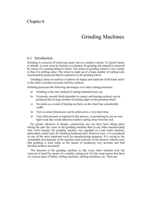
  • 1. Chapter 6 Grinding Machines 6.1 Introduction Grinding is a process of removing metal, but in a smaller volume. To 'grind' means to 'abrade', to wear away by friction or to sharpen. In grinding, the material is removed by means of a rotating abrasive wheel. The action of grinding wheel is very similar to that of a milling cutter. The wheel is made up of a large number of cutting tools constituted by projected abrasive particles in the grinding wheel. Grinding is done on surfaces of almost all shapes and materials of all kinds and it is also able to produce accurate and fine surfaces. Grinding possesses the following advantages over other cutting processes: a) Grinding is the only method of cutting hardened steel, etc. b) Extremely smooth finish desirable at contact and bearing surfaces can be produced due to large number of cutting edges on the grinding wheel. c) No marks as a result of feeding are there, as the wheel has considerable width. d) Very accurate dimensions can be achieved in a very short time. e) Very little pressure is required in this process, so permitting its use on very light work that would otherwise tends to spring away from the tool. Far greater advances in design, construction any use have been taking place during the past few years in the grinding machine than in any other machine-shop tool. Until recently the grinding machine was regarded as a tool room machine, particularly useful only for finishing hardened steel. However now, it is considered as one of the most important tools for manufacturing purposes. It is owing to the remarkable development of the machine itself and also of the abrasive wheels used, that grinding is used today as the means of producing very accurate and find finished surfaces accurately. The function of the grinding machine is, like every other machine tool, the removal of metal by means of a suitable cutting tool. For the same reason that there ire various types of lathes, milling machines, drilling machines, etc. There are
  • 2. 6.2 various types of grinding machines. A few types of grinding machines are briefly described as follows; 6.2 Kinds of Grinding Grinding is done on surfaces of almost all conceivable shapes and materials of all kinds. Grinding may be classified broadly into two groups 1) Rough or non-precision grinding 2) Precision grinding 6.2.1 Rough Grinding The common forms of rough grinding are snagging and offhand grinding where the work is held in the operator's hand. The work is pressed hard against the wheel, of vice-versa. The accuracy and surface finish obtained are of secondary importance. Snagging is done where a considerable amount of metal is removed without regard to the accuracy of the finished surface. Examples of snag grinding are trimming the surface left by sprues and risers on castings, grinding the parting line left on castings, removing flash on forgings, the excess metal on weld cracks, and imperfections on alloy steel billets. 6.2.2 Precision Grinding This is concerned with producing good surface finish and high degree of accuracy. The wheel or works both are guided in precise paths. Grinding, in accordance with the type of surface to be ground, is classified as: 1) External cylindrical grinding 2) Internal cylindrical grinding 3) Surface grinding 4) Form grinding. 6.2.2.1 External Cylindrical Grinding It produces a straight or tapered surface on a workpiece. The workpiece must be rotated about its own axis between centers as it passes lengthwise across the face of a revolving grinding wheel. 6.2.2.2 Internal Cylindrical Grinding It produces internal cylindrical holes and tapers. The workpieces are chucked and precisely rotated about their own axis. The grinding wheel or, in the case of small bore holes, the cylinder wheel rotates against the sense of rotation of the workpiece. 6.2.2.3 Surface Grinding It produces flat surface. The work may be ground by either the periphery or by the end face of the grinding wheel. The work piece is reciprocated at a constant speed below or on the end face of the grinding wheel.
  • 3. Grinding Machines 6.3 6.2.2.4 Form Grinding It is done with specially shaped grinding wheels that grind the formed surfaces as in grinding gear teeth, threads, splined shafts, holes and spheres, etc. The first three basic kinds of precision grinding are illustrated in Fig. 6.1. Fig.6.1. Basic kinds of precision grinding 6.3 Types of Grinding Machines Grinding machines, according to the quality of surface finish, may be classified as: 1) Rough grinders 2) Precision grinders 6.3.1 Rough Grinders Rough grinders are those grinding machines whose chief work is the removal of stock without any reference to the accuracy of the results. They are mainly of the following types: 1) Floor stand and bench grinders 2) Portable and flexible shaft grinders 6.3.2 Precision Grinders Precision grinders are those that finish parts to a very accurate dimensions. According to the type of surface generated or work done they may be classified as follows: 1) Cylindrical grinders a) Centre-type (plain) b) Centre-type (universal) c) Centre less. 2) Internal grinders a) Chucking ,
  • 4. 6.4 i) Plain ii) Universal b) Planetory c) Centreless 3) Surface grinders a) Reciprocating table i) Horizontal spindle ii) Vertical spindle b) Rotating table i) Horizontal spindle ii) Vertical spindle 4) Tool and cutter grinders a) Universal b) Special 5) Special grinding machines. 6.4 Cylindrical Grinders The principle of cylindrical grinding is illustrated in the Fig. 6.2. In this method or grinding the work piece usually held between dead centers and rotated by a dog and driver on the face plate. The work may also be rotated about its own axis in a chuck. The grinding wheel in contact with the work removes metal from its circumference. Fig.6.2. Principle of cylindrical grinding
  • 5. Grinding Machines 6.5 There are four movements in a cylindrical centre type grinding a) The work must revolve b) The wheel must revolve c) The work must pass the wheel and d) The wheel must pass the work. These grinding machines are intended primarily for grinding plain, cylindrical parts, althrough they can also be used for grinding contoured cylinders, tapers, faces and shoulders, fillets, and even cams and crankshafts. 6.5 Plain Centre Type Cylindrical Grinding Machine A plain centre-type grinding machine is shown in that Fig. 6.3 It is essentially a lathe on which a grinding wheel has been substituted for the single point tool. It consists of the following parts. 1) Base 2) Tables 3) Head stock 4) Tail stock 5) Wheel head 6.5.1 Base The base or bed is the main casting that rests on the floor and supports the parts mounted on it on the top of the base precision horizontal ways set at right angles for the table to slide on the base. The base also houses the table drive mechanism. Fig.6.3. Block diagram of a plain centre-type grinder
  • 6. 6.6 6.5.2 Tables There are two tables, lower table and upper table. The lower table slides on ways on the bed and provides traverse of the work past the grinding wheel. It can be moved by hand or power within desired limits. The upper table is pivoted at its centre is mounted on the top of the sliding table. It has T-slots for securing the headstock and tailstock or footstock and can be positioned along the table to suit the length of the work. The upper table can be swivelled and clamped in position to provide adjustment for grinding straight or tapered work as desired setting for tapers up to ยฑ 10ยฐ can be made in this way steep tapers are ground by swivelling the wheel head. Adjustable dogs are clamped in longitudinal slots and they are provided at the side of the lower or sliding table and are set up to reverse the table at the ends of the stroke. 6.5.3 HeadStock The headstock supports the work piece by means of a dead centre and drives it by means of a dog, or it may hold and drive the work piece in a chuck. 6.5.4 TailStock The tailstock can be adjusted and clamped in various positions to accommodate different lengths of work piece. 6.5.5 Wheel Head The wheel head carries a grinding wheel and its driving motor is mounted on a slide at the top and rear of the base. The wheel head may be moved perpendicularly to the table ways, by hand or power, to feed the wheel to the work. 6.5.6 Cross Feed The grinding wheel is fed to the work by hand or power as determined by the engagement of the cross feed control lever. On plain grinding machines, the operation may be stopped automatically, when the workpiece has been finished to size. In one method, it uses an automatic caliper type gauging attachment to measure the work piece and stop the operation at the proper time. 6.6 Universal Centre-Type Grinders Universal grinders are widely used in tool rooms for grinding tools, etc. a universal machine has the following additional features: 1) The headstock spindle may be used alive or dead, so that the work can be held and revolved by a chuck as well as ground between centers. 2) The headstock can be swivelled at an angle in a horizontal plane.
  • 7. Grinding Machines 6.7 3) The wheel head and spindle can be swiveled and traversed at any angle. The wheel head can also be arranged for internal grinding by the addition of an auxiliary wheel head to revolve small wheels at high speeds. 6.7 Centreless Grinders Centreless grinding is a method of grinding exterior, cylindrical, tapered and formed surfaces on work pieces that are not held and rotated on centers. The principal elements of an external Centreless grinder shown in Fig. 6.4 are: 1) Grinding wheel 2) Regulating wheel and 3) Work rest 6.7.1 Grinding wheel It is a large wheel. 6.7.2 Regulating Wheel or Back up Wheel It is a small wheel and is of rubber bonded abrasive wheel having the frictional characteristics to rotate the work at its own rotational speed. It holds the work piece against the horizontal force of action controlling its size and imparting the necessary rotational and longitudinal feed. The speed of regulating wheel various from 15 to 60 mts/min. Both wheels are rotated in the same direction. 6.7.3 Work Rest It gives the necessary support to the work-piece against the cutting forces. The slope of its edge with the regulating wheel provides the 'V formation into which the work seats. 6.7.4 Feed of the Work Piece As shown in the Fig. 6.4 (side view) the regulating wheel is inclined at an angle of 0 to 8 or 10 degrees to the grinding wheel. This arrangement gives the axial movement of the work past the grinding wheel. Fig. 6.4. External Centreless grinding
  • 8. 6.8 6.8 Surface Grinder Surface grinding is a term generally used to describe the grinding of flat surfaces. Many parts that were formely machined on milling machines and shapers are now machined on surface grinders. Surface grinders can be classified as: i) Planer type (reciprocating table) Rotary type (revolving table) 36 In both the above types, thai spindle can be either horizontal or vertical 6.8.1 Reciprocating Table Surface Grinder The horizontal spindie, reciprocating table surface grinder using the periphery of a straight wheel, is the most common surface grinder. They are built in a wide range of sizes for flat grinding the size of a surface grinder is determined by the size of the surface to be ground. The machine with reciprocating table is particularly suited to pieces that are long or have stepped profiles at right angles to the direction of motion. For most of the operations on surface grinders, the work piece is held on a magnetic chuck. The magnetic chuck is widely used as it is fast to apply and will hold a large number of small pieces for grinding. Parts can also be held in fixtures like V-blocks. Angle plate or a vise fitted to the table. Reciprocating table surface grinder (spindle horizontal and vertical) are shown in Fig. 6.5 (a) and (b). 6.8.2 Rotary Table Surface Grinder The machine with rotary table is widely used for continuous rapid grinding. Horizontal spindle rotary table machines, using the periphery of a straight wheel are not used to a great extent. They are usually constructed in small sizes. Vertical spindle rotary table machines, using cylinder wheels or segments are built with one to five spindles mounted on a central column. These machines are used so that roughing and finishing cuts can be taken on large parts with only one pass through the machines. Rotary table surface grinder (spindle horizontal and vertical are shown in Fig. 6.5 (c) and (d). (a) Horizontal spindle reciprocating (b) Vertical spindle reciprocating table table
  • 9. Grinding Machines 6.9 Fig.6.5. Types of surface grinders 6.9 Tool and Cutter Grinder When milling cutters, reamers or drills become dull, they need grinding. A tool and cutter-grinding machine (Fig. 6.6) is used to sharpen such cutters. The grinder can grind plain cylindrical cutters, angular cutters, end mills, formed cutters, reamers, taps and other cemented carbide tools. They are classified as: 1) Universal tool and cutter grinder 2) Single purpose tool and cutter grinder. Universal tool and cutter grinder is intended for sharpening of miscellaneous cutters, whereas single purpose grinder is used for grinding tools such as drills, tool bits, etc, for production plants. Fig.6.6. Tool and cutter grinder A universal tool and cutter grinder has a heavy, rugged base with a saddle mounted on the top of the base. The column supporting the wheel head is mounted on the saddle and it can be moved up and down and swivelled.
  • 10. 6. 10 The table moves on a top base, which is mounted over the saddle. The top of the base contains the gears and mechanism, which controls the table movement. The headstock and tailstock are mounted on either side of column on the base of the machine. It can be swivelled and positioned on the base for varied set ups. 6.10 Special Grinding Machines In special grinding machines, the form grinder and gear grinder are very important. 6.10 J. Form Grinder In form grinding, a formed wheel feeds towards the revolving work, which does not traverse. The wheel has the exact shape and form of the profile to be ground. Fig.6.7 shows the form grinding. Fig.6.7. Form grinding 6.10.2 Thread Grinder In thread grinding, the profile of the grinding wheel depends on the shape of the thread to be ground. The wheel is so formed as to have the exact shape of the thread. Fig. 6.8 shows thread grinding. Thread of any form can be ground on these machines, either from a blank or as finishing operation after milling. 6.10.3 Gear Grinder As shown in Fig.6.9, this grinder makes use of a formed wheel, shaped exactly to the profile of the shape between two adjacent teeth. This curved profile varies for each change in gear diameter, or for each change in number of teeth. Such a profile is difficult to form and maintain. A rough-cut gear is mounted on an arbor and the arbor is held in an indexing and locking work head. With the gear locked in position, it is reciprocated slowly under the wheel. At proper intervals, indexing head shifts the gear from one tooth position to the next. Fig. 6,8. Thread grinder Fig.6.9. Gear grinding
  • 11. Grinding Machines 6.6 6.11 Newly Developed Grinding Machines Automation has been associated with advancement in technology. In the process of automation for small batch production and mass production, hydraulic tracer controlled machine tool and programmed operating cycle machine tools have been evolved. However, this requires templates, cams, stops, electrical trip dog's timers etc. Keeping automatic in mind different types of machines have been developed for the operations, which were being done before, using some attachments for fixtures on cylindrical, internal, surface and Centreless grinding machines. Thus required jobs are being done achieving better results in minimum time, with out fatigue. 6.11.1 Centreless Grinding Machine With Profile Dressing Both the grinding and the regulating wheel heads are provided with hydraulically operated wheel dressers having stepless variable dressing speeds and are controlled independently. Profile dressing is possible with the interchangeable copy template. Top slide of dressing units is mounted on preloaded antifriction ball guide ways. A spring-loaded stylus against a template achieves high copying accuracy. 6.11.2 Roll Camber Grinding Machine This machine is suitable for grinding rolls with either concave or convex cambering. It can also be used for normal cylindrical grinding. The cambering on the roll is produced by copying it from a master template fitted on rear side of the bottom table. Based on the profile of the template, a torque is transmitted to ball screw and nut through lever arrangement for small in feed movement of grinding wheel. The in feed slide of the machine, i.e., wheel head is on antifriction ways. The grinding operation is achieved with micronic precision, as the transfer from template to wheel head takes place through ball screw and nut arrangement. The screw and nuts are hydraulically preloaded. By adjusting the lever length (Fig. 6.10) different values of camber with the same template can be acheived. To adjust the required camber, it is necessary to move the follower arm to the predetermined position on the lever arm. Fig. 6.10. Principle of roll camber grinding machine.
  • 12. 6. 12 6.11.3 Duplex Grinder Duplex grinder is a surface-grinding machine used to generate to parallel surfaces at high production rate. The machine has two grinding heads and utilises the faces of bonded grinding wheels fastened to steel plates which are in turn attached to spindle face plate. The two grinding wheels (Fig. 6.6) are running in opposite direction and work pieces are fed between them to grind two parallel faces simultaneously to close tolerance and fine finish. The production rate is quite high in this machine. Piston rings can be produced at a rate of about 1500 pieces/hour attaining flatness and parallelelism within 0.01mm. Fig.6.11. Duplex Grinder The finish and flatness obtained by this process is better than any other grinding process using periphery of grinding wheel. 6.11.4 Angular Wheel Head Grinder With Profile Dressing For grinding multiple diameters, shoulders and profiles in one plunge cut, the wheel is trued with a hydraulic copy-truing device mounted on the wheel head. In this machine, wheel head is swivelled and fixed at 30ยฐ to the work axis (Fig. 6.12), by doing so, wheel width is increased and facing on job becomes easier. Fig.6.12. Angular wheel head grinder 6.2 Various Terms Related to Grinding Wheel Various terms related to grinding wheel like abrasives, bond, grain size, grade, structure and grinding ratio are explained as follows. *.'โ€ขโ– -โ–  6.12.1 Abrasives Grinding wheels are made of abrasive particles bonded together by suitable bond.
  • 13. Fig.6.13. Abrasive grains Abrasives can be classified as below: Abrasives Natural abrasives Artificial abrasives a) Sand stone or solid quartz. b) Emery c) Corundum d) Diamonds e) Garnet a) Silicon carbide b) Aluminium oxide c) Boron carbide d) Zirconium oxide 6.12.1.1 Efficiency of Abrasive Particle The efficiency of abrasive particle depends on 1) Purity 2) Uniformity in composition 3) Hardness 4) Tough ness: if the abrasives are not tough, the wheel will fracture readily. 5) Sharpness of fracture: better cutting action is obtained by sharp edge abrasives natural abrasives give rounded edges and are not efficient in cutting. 6.12.2 Manufacture of Abrasive 6.12.2.1 Sandstone Sandstone wheels are rarely used. Although they are cut from high grade quartz or sandstone, yet they do not wear evenly because of variation in the natural bond. Grinding Machines 6.13 An abrasive is a hard material, which can be used to cut or wear away other materials. Abrasive grains of silicon carbide are shown in Fig. 6.13. [
  • 14. 61.4 6.12.2.2 Corundum and Emery Both are composed of crystal aluminum oxide in combination with iron oxide and other impurities. These minerals lack in uniform bond and are seldom used in production. 6.12.2.3 Diamond Wheels They are made with resinoid bond and are useful in sharpening cemented carbide tools. Due to their rapid cutting ability, slow wear, free cutting action they are quite economical very little heat is generated with their use. 6.12.2.4 Silicon Carbide It was discovered during an attempt to manufacture precious gems in an electric furnace. The hardness of this material according to Moh's scale is lightly over 9.5, which approaches the hardness of a. diamond. Raw materials consisting of silicon sand, petroleum, coke saw dust and salt are heated in a furnace to around 2300ยฐc and held there for a considerable period of time. The product consists of a mass of crystals surrounded by partially unconverted raw material. After cooling, the material is broken up, ground and crushed to grain size silicon carbide crystals are very sharp and extremely hard. 6.12.2.5 Aluminum Oxide It is made from the clay-like mineral "bauxite" which is the main source of aluminium, aluminium oxide is slightly softer than silicon carbide, but is much tougher. Most manufactured wheels are made from aluminium oxide. 6.12.3 Bonding Material A bond is a material that holds the abrasive grains together enabling the mixture to be kept to be kept in desired as below. 1) Vitrified bond ~>V 2) Silicate bond -> S 3) Shellac bond ->E 4) Rubber bond ->R 5) Resinoid bond (Bakelite) -ยปB 6) โ–  Resinoid reinforced ->BF The bonding material should have the following properties: 1) The bonding material should withstand the grinding temperature. 2) It should be able to withstand the spindle speed without disintegrating. 3) The bonding material should be capable of retaining the abrasive grains during cutting action. 4) It should be friable enough to dislodge the worn grits. 5) The bond should be rigid to enable the grit to penetrate and cut the work.
  • 15. Grinding Machines 6.15 6.12.4 Various Types of Bonds are as Follows 6.12.4.1 Vitrified Bond The abrasive grains are mixed with clay-like ingredients that are changed to glass- like material upon being burnt at high temperature. Addition of water is required and the wheels are shaped in metal molds under a hydraulic press. The time for burning varies with wheel size, being anywhere from 1 to 14 days. These wheels are porous, strong, unaffected by water, acid oils and climatic or temperature conditions. Vitrified bonds are used for most grinding operations. The maximum standard speed generally used for vitrified bond wheels is 33m/sec. 6.12.4.2 Silicate Bond Silicate bond require much lower temperature to harden the wheel than so vitrified bonds. In this sodium silicate is mixed with abrasive grains and mixture is tapped in metal molds. After drying for several hours, the wheels are baked at 260ยฐc from 1 to 3 days. Silicate wheels release the grains more readily giving a milder (or cooler) grinding action and are suitable for grinding edge of tools. The process is recommended for large wheels, as they tend not to track or warp in the baking process. 6.12.4.3 Shellac Bond Shellac bond, initially used for cut-off operations are also used for hardened materials. The abrasive grains are first coated with shellac by being mixed in a steam-heated mixer. The material is then placed in heated molds and rolled or pressed. The wheels are finally baked for few hours at 150ยฐc. This bond is adopted for thin wheels, as it is strong and elastic. Alkaline cutting fluids react with this bond. 6.12.4.4 Rubber Bond Pure rubber with sulphur as a vulcanizing agent is mixed with abrasives by feeding the material between heated mixing rolls. After it is rolled to thickness, the wheels are cut out with dies and vulcanized under pressure. Very thin wheels can be made by this process. Rubber bonded wheels are used for high speed grinding (45-80m/s) As they afford rapid removal of the stock, these wheels are used for cut-off operations. When subjected to heat, the bond softens and releases the grains. Thus, cutting fluid should normally be used with this bond. 6.12.4.5 Bakelite or Resinoid Bond Abrasive grains in this process are first mixed with thermosetting synthetic resin powder and liquid solvent, then molded and baked. The bond is very hard and strong and can be operated at speed of 45-80m/s. it is used for general purpose grinding and for snagging purposes. 6.12.4.6 Oxychloride Bond This bond contains oxides and chlorides of magnesium in contrast with other bonding materials. Oxychloride is a cold setting cement requiring an aging period. As most cutting fluids affect this bond, it is normally used for dry grinding.
  • 16. 6.16 Metal Cutting & Machine Tools 6.12.5 Grain Size Abrasives must be refined and reduced to standard sizes before they are manufactured in to wheels. For this, the abrasives are crushed and screened, that is they are passed through screens containing meshes of standard sizes. There sizes are measured by the number of meshes per inch through, which the grains will pass. For example, a grain that passes a screen having 20 mesh opening per inch is called a 20 grit size and measures roughly 1/20 inch across. The grain size is indicated by grit number as shown below. Coarse grain -> 4, 5, 6, 7, 8, 10, 12, 14, 16, 20, 24 Medium grain -> 30, 36, 46, 54, 60 Fine grain -> 70, 80, 100, 120, 150, 180 Very fine grain -> 220, 240, 280, 320, 400, 500, 600, 800, 1000, 1200 6.12.6 Grade Grade of a wheel is a measure of how strongly the grains are held by the bond. The bonding material in a wheel surrounds the individual grains and links them together. Different types of grades are represented by English letters from A to Z, as shown below. AtoH ->Soft I to P -> Medium Q to Z -ยป Hard Different types of wheel grade are shown in the Fig. 6.14. Fig. 6.14. Wheel grades
  • 17. Grinding Machines 6.17 6.12.7 Structure The structure of grinding wheel refers to relationship of abrasive grain and bonding material and of these two elements to the void between them. Different types of structures are represented by range of numbers. 1 to 8 โ€”> Dense 9 to 16 -> Open 6.12.8 Grinding Ratio It is defined as the ratio of the volume of material removed to the volume of wheel wear. The grinding ratio depends on parameters such as the type of wheel, wheel speed, cross-feed, down-feed, and the grinding fluid used. Values ranging from a low of 2 to over 200 have been observed in practice. A high grinding ratio, however, may not necessarily result in the best surface integrity of the part. 6.12.9 Grinding Wheel Shapes Fig.6.15. Standard grinding wheel! shapes
  • 18. 6. 18 s Straight wheel, wheel recessed on one side and wheel recessed both sides are classified as straight wheel types and are used for cylindrical grinding, surface grinding, off-hand grinding and snag grinding. The recess is provided to give clearance for mounting flanges. Tapered wheel is used for snag-grinding operations. Cylinder wheel type is used on either horizontal or vertical spindle surface-grinding machine. Either the peripheral surface or the face of the wheel is used as the grinding surfaces. A straight cup wheel is used on horizontal or vertical spindle surface grinding machine. It is also used for off-hand grinding. The wheel face may be plain or beveled. Saucer wheel is used primarily for resharpening saws flaring cup and dish wheel are used for tool and cutter grinding. The flaring cup shape, which may have plain or bevelled face, is also used in conjunction with a resinoid bond as a snag-grinding wheel. Various grinding wheel shapes are shown in Fig. 6.15. 6.13 Factors in the Selection of Grinding Wheels The following factors must be considered while selecting a grinding wheel. 6.13.1 Constant Factors The most important factor to be considered is the material to be ground, which influences the selection of the abrasive, grain size, grade, structure and bond. Some manufacturers recommend that abrasive should be aluminium oxide for steel and its alloys and silicon carbide for cast iron and non-ferrous metal. The grain size, a fine grain for hard and brittle materials and coarse grain for soft ductile materials. The grade of wheel hard wheel for soft materials and soft wheel for hard materials the structure, dense structure for hard the grade of wheel hard wheel for soft meterials and brittle materials and open structure for soft and ductile materials. At times the bond selection is affected by the material to be ground, but more often it is influenced by the variable factors explained later. The next constant factor considered is the accuracy and finish needed. It affects the selection of grain size and the bond. The grain size should be coarse for rough cutting and fine for fine finishing. The bond used should be vitrified for roughing and resinoid, rubber and shellac for high finish. The third factor is the area of contact. It influences the grain size, grade and structure. It is recommended that grain size should be fine for small areas of contact and coarse for large areas on contact. The grade recommended is the area of contact, harder the wheel. For structure, dense structure is recommended for large area of contact. . The forth-constant factor considered is the nature of the grinding operation. It affects the bond used precision grinding calls for vitrified bonded wheels. If an exceptionally fine finish is desired, one of the organic bond (resinoid, rubber or shellac) can be used. 6.13.2 Variable Factors There are four variable factors to be considered. The first variable factor is wheel speed. It influences the grade and the bond of the wheel.
  • 19. Grinding Machines 6.19 It is recommended that higher the wheel speed, softer should be the wheel. Resinoid bonds can be generally used at higher speeds than vitrified bond wheels. The second variable factor is rate of feed. The affects only the grade of the wheel. It is suggested that higher the rate of feed, the harder should be the wheel. The third variable factor is condition of the grinding machine. Spindles that are loose in their bearings and have shaky foundations necessitate use of harder wheel than would be needed if the machine were in better condition. The fourth factor is the operating characteristics. The man on piecework usually requires a harder wheel than the man paid on a day-work basis. | 6.14 Standard Codification of a Grinding Wheel Due to the diversity of methods employed by the various grinding wheel manufactures for the making of grinding wheels, a new marking system has been accepted as I standard. It is divided into six parts, with the markings placed in the following sequence. Position-l Position-2 LPosition-3 Position-4 Position-5 Position-6 Kind of abrasive and Grain size Grade Structure Bond type Manufacturer manufacture record. r's prefix Fig. 6.16 shows how a specific wheel is marked and how it should be ordered from the manufacturer. The craft shows that a grinding wheel marked 51 A-36-L-5-V-93 has been chosen. The letters and numbers contained in this identification are explained in the figure. This codification is as per bureau of Indian standard code Is 551: 1989. 6.15 Cutting Speed and Work Speed The Cutting speed (V) is the relative speed of the wheel Vw (Peripheral speed) and the work piece. It is expressed in m per sec with sufficient approxmation, it may be considered that Where Dw is the diameter of grinding wheel in mm, and nw is the speed of the wheel in r.p.s. The work speed Vp is expressed in m/min and is determined by the formula: Where, c is the coefficient which depends on the type of grinding and the material to be ground, T = is the wheeel life in min. betweeen dressings d = is the work diameter in min,
  • 20. Fig.6.16. Grinding wheel marking system chart.
  • 21. Grinding Machines 6.21 t = is the depth of cut s = is the feed per work revolution in mm per revolution. Z, Y, X and m are exponents which are determined, together with C.from hand work data. The speed in r.p.m of the work is determimed from the formula 6.16 Feed The feed (S) in cylindrical grinding in the longitudinal movement of the workpiece per revolution, it is expressed in mm per revolution of the work piece. Longitudeinal feed's usually from 0.6 to 0.9 of the face with for finish grinding. The longitudinal feed (Si) of the work per revolution should be less than the face width of the wheel and depends on whether rough or finish grinding is being performed. The feed is plunge-cut grinding (SP) is in a radial direction and the operation is done in one pass. In this case, the face width is equal to the length of the work to be ground. 6.17 Depth of Cut The depth of cut (t) is the thickness of the layer of metal removed in one pass. It is expressed in mm. The depth of cut is taken in a range from 0.005 to 0.04 mm. 6.18 Machining Time in Grinding Machining time for cylindrical grinding is determined from the formula: i โ€”-'โ€” k min. '" S.n i p Where L = is the length of longitudinal travel in mm. i = is the number of pass, S = is longitudinal feed in mm per revolution, np = is the speed of the work piece in r.p.m, k is a coefficient depending on the specified grade of accuracy and class of surface finish (for rough grinding k = 1 to 1.2 for finish grinding k = 1.3 to 1.7). For plunge-cut cylindrical grinding where a is the grinding allowance n each side in mm. Sc is the cross feed in mm per revolution