SlideShare ist ein Scribd-Unternehmen logo
1 von 20
HYDRAULIC SYSTEM
Hydraulic system:
A industrial hydraulic system is fluid circuit based on hydrostatic principle that uses
pressurized hydraulic fluid to power hydraulic machinery.
There are 2 types of hydraulic circuits used in fluid power applications.
Open Loop Circuits:
These are circuits where the inlet of hydraulic pump and the actuator(or valve)
return are connected to a hydraulic reservoir.
Closed Loop Circuits:
These are circuits where the motor return is connected directly to the hydraulic
pump inlet .
• Hydraulic system installed in gasification unit is Open Loop Circuits supplied by
M/s Rexroth.
• Hydraulic system in unit-3 is divided into 3 verticals
1.Power pack
2.Working field circuit
3.Recirculation unit
Hydraulic oil reservoir Main header pump
Discharge filter
& NRV
Field
working
circuit
Main header
accumulator
Line
accumulator
filter
Bearing
flushing line
Return
line PSV
Power pack
Drain
line
Hydraulic reservoir
 Tank capacity-6000 lit
 Material- Stainless steel with tank inside Epoxy coated.
 Design for atmospheric pressure & temp 20-70o c
 Reservoir divide with main pump suction chamber & Return line
chamber.
 Oil chambers are provided by 4o slope from centre to out word for
easy removal of dirt particle.
 Reservoir Fitted with two breather for filtration & dehumidification of
intake air.
 Reservoir maximum & minimum oil level
>68%– warning HH
>65%– warning H
> 33%– warning L
>24%– warning LL
 Reservoir maximum & minimum oil Temperature
>62oc– warning HH
>60oc – warning H
HYDRAULIC OIL
 HFDR-46 synthetic oil is used in our hydraulic system.
Properties of HFDR-46
 Fire resistant hydraulic fluid based on selected phosphate esters
Good lubrication performance and anti-wear properties.
Excellent oxidation stability.
Prevention of foaming and very quick air release
Main Hydraulic pump
• 4 no's of Multiaxial piston pump installed considering 3 no's pump
in continuous operation & 1 pump for standby condition.
 Type-A4VSO180 Variable displacement type pump.
 Capacity-223 l/m
 discharge pressure-110kg/cm2,
 Efficiency-93.5%
 Best operating viscosity range 16 to 43 centistoke.
Require Minimum Cleanliness level ISO 20/18/15
NAS & ISO 4406 interconversion
Maximum Contamination Limits (per 100 mL)
Size range in microns
Approximate
ISO 4406
Equivalent
NAS 1638
code
5-15 µm 15-25 µm 25-50 µm 50-100 µm Over 100 µm
— 00 125 22 4 1 0
— 0 250 44 8 2 0
12/10/7 1 500 89 16 3 1
13/11/8 2 1000 178 32 6 1
14/12/9 3 2000 356 63 11 2
15/13/10 4 4000 712 126 22 4
16/14/11 5 8000 1425 253 45 8
17/15/12 6 16,000 2850 506 90 16
18/16/13 7 32,000 5700 1012 190 32
19/17/14 8 64,000 11,400 2025 360 64
20/18/15 9 128,000 22,800 4050 720 128
21/19/16 10 256,000 45,600 8100 1440 256
22/20/17 11 512,000 91,200 16,200 2880 512
23/21/18 12 1,024,000 182,400 32,400 5760 1020
DICHARGE & RETURN LINE FILTER
• General: Filter clogging indicators to be evaluated only when fluid
temperature is higher than 30o C.
• Each discharge line of main pump Fitted with 10 micron filter.
> 5 kg/cm2 – warning H
> 7 kg/cm2 - warning HH
• Return line fitted with 10 micron filter.
> 2 kg/cm2 - warning H
> 4 kg/cm2 - warning HH
ACCUMULATOR SECTION
Main accumulator
• 2 no's accumulator having each capacity 180 L.
• Accumulator fitted with 8 no's (8*75=600 l) of nitrogen cylinder.
Line Accumulator
• Total 4 no's of line accumulator present at 5 meter & 21 meter
• Each capacity 30 litre .
WORKING FIELD CIRCUIT
Pressure
reducing
valve
solenoid DC
Valve
Flow control
Circuit
selection
Actuator
Mimic panel
accumulator Pressure
reducing
valve
Optional Valve
PRESSURE REDUCING VALVE
• 2 pressure reducing valve in parallel connection (Size-NG20)
• General pressure setting 65kg/cm2 & 67kg/cm2
• Extra pressure reducing valve for dv6,dv2,dv4 & ash lock bottom cone.
• General pressure setting for reducing valve is 30kg/cm2.
SOLENOID OPERATED DC VALVE
• we are using 4/2 or 4/3 DC solenoid valve with hydraulic pilot line operated.
• Always we have extra solenoid DC valve for avoiding any malpractice situation.
FLOW CONTROL
• Meter in type flow control are installed in our hydraulic circuit.
• Main purpose of this meter in type circuit is velocity control in our actuator.
CIRCUIT SELECTION
• Each circuit has 2 no's of solenoid operated DC valve.
• Out of which we can choose running & isolation of any DC valve by manual ball
valve.
ACTUATER
• In our circuit only linear type actuators are used with different size.
• Every actuator Fitted with cushioning for avoiding damage of piston seal &
equipment.
• Maximum speed of actuator is .2m/sec.
• Gasifier area operating actuator hydraulic pressure.
Sl no Equipment actuator name Operating pressure
1 Coal feeding chute 65kg/cm2
2 Coal lock top cone 30kg/cm2
3 Coal lock bottom cone 65kg/cm2
4 Ash lock top cone 65kg/cm2
5 Ash lock bottom cone 30kg/cm2
6 DV1 valve 65kg/cm2
7 DV2 valve 30kg/cm2
8 DV5 valve 65kg/cm2
9 DV6 valve 30kg/cm2
10 PV1 valve 65kg/cm2
RECIRCULATION PART
Hydraulic oil
Reservoir
Recirculation
pump
Filtering Unit Cooling unit
Main pump
bearing
flushing line
Temp sense
bypass line
Filling
pump
NRV
RECIRCULATION PUMP
• 2no’s of Screw pump(1 running & 1 standby) are used for cooling purpose having
capacity 110 l/min.
• Working pressure 10kg/cm2 & efficiency 93.5%.
• Self priming type screw pump with triple screw.
FILLING PUMP
• 1 no of Screw pump is used for filling purpose having capacity 13l/ min.
• Working pressure 5kg/cm2 & efficiency 93.5%.
FILTERING UNIT
• We are using 6 micron duplex filter for recirculation unit .
• > 2 kg/cm2 - warning H
• > 4 kg/cm2 - warning HH
COOLING UNIT
• We are using shell & tube type Heat exchanger for cooling purpose
with 1 stand by condition.
• Cooling water flow 100 lit/min at maximum 35ocentigrade.
• Cooling water inlet to the heat exchanger control by thermostatically
reservoir temperature.
Daily pm check list
FREQUENT PRBLEMS
• Leakage from hydraulic hose.
• Looseness of QRC
• Malfunction of solenoid DC valve.
• Increase of hydraulic oil temperature.
MAJOR FAILURE
• Recirculation pump seal failure.
• Main header pump flow problem.
THANKS

Weitere ähnliche Inhalte

Ähnlich wie Hydraulic ppt.pptx

Coconut water extraction mass production machine
Coconut water extraction mass production machineCoconut water extraction mass production machine
Coconut water extraction mass production machineLuis Cabrera
 
Bombas de Refrigeração Hermetic
Bombas de Refrigeração HermeticBombas de Refrigeração Hermetic
Bombas de Refrigeração HermeticVibropac
 
Designer and operator manual dorot
Designer and operator manual dorotDesigner and operator manual dorot
Designer and operator manual dorotCarlos Rovello
 
Designer and operator manual dorot
Designer and operator manual dorotDesigner and operator manual dorot
Designer and operator manual dorotCarlos Rovello
 
Bl novaplex integral_process_diaphragm_pumps_117_gb
Bl novaplex integral_process_diaphragm_pumps_117_gbBl novaplex integral_process_diaphragm_pumps_117_gb
Bl novaplex integral_process_diaphragm_pumps_117_gbmohd kamal mastuki
 
Electrical_Submersible_Pump (final).ppt
Electrical_Submersible_Pump (final).pptElectrical_Submersible_Pump (final).ppt
Electrical_Submersible_Pump (final).pptAnkit732751
 
TECHNOLOGY FOR HIGH YIELD IMPROVEMENT IN PRODUCED WATER QUALITY
TECHNOLOGY FOR HIGH YIELD IMPROVEMENT IN PRODUCED WATER QUALITYTECHNOLOGY FOR HIGH YIELD IMPROVEMENT IN PRODUCED WATER QUALITY
TECHNOLOGY FOR HIGH YIELD IMPROVEMENT IN PRODUCED WATER QUALITYiQHub
 
Fuel gas system of gas production
Fuel gas system of gas productionFuel gas system of gas production
Fuel gas system of gas productionPhyoe Maung Maung
 
Effective decisions for the complicated well market on the basis of submersib...
Effective decisions for the complicated well market on the basis of submersib...Effective decisions for the complicated well market on the basis of submersib...
Effective decisions for the complicated well market on the basis of submersib...Dmitry Kuraev
 
anaesthesia machine-140810030802-pptx.pptx
anaesthesia machine-140810030802-pptx.pptxanaesthesia machine-140810030802-pptx.pptx
anaesthesia machine-140810030802-pptx.pptxRaj Kumar
 
Microsoft PowerPoint - DEV of Dual Filling
Microsoft PowerPoint - DEV of Dual FillingMicrosoft PowerPoint - DEV of Dual Filling
Microsoft PowerPoint - DEV of Dual FillingPRAN-RFL Group
 
Hydro Power Plant Auxaleries
Hydro Power Plant AuxaleriesHydro Power Plant Auxaleries
Hydro Power Plant AuxaleriesMahajan Saurabh
 
Wcfx r134a - hermatic screw chiller
Wcfx r134a - hermatic screw chillerWcfx r134a - hermatic screw chiller
Wcfx r134a - hermatic screw chillerAruna Amarasekara
 
Pump api 675 presentation
Pump api 675 presentationPump api 675 presentation
Pump api 675 presentationVothanh Trung
 
Inplant training report
Inplant training reportInplant training report
Inplant training reportapplesam8
 
Automação Pneumática para Máquinas CKD CORP - AERODYNAMIC TECHNOLOGY
Automação Pneumática para Máquinas CKD CORP - AERODYNAMIC TECHNOLOGYAutomação Pneumática para Máquinas CKD CORP - AERODYNAMIC TECHNOLOGY
Automação Pneumática para Máquinas CKD CORP - AERODYNAMIC TECHNOLOGYJúlio Gengo
 

Ähnlich wie Hydraulic ppt.pptx (20)

Coconut water extraction mass production machine
Coconut water extraction mass production machineCoconut water extraction mass production machine
Coconut water extraction mass production machine
 
Bombas de Refrigeração Hermetic
Bombas de Refrigeração HermeticBombas de Refrigeração Hermetic
Bombas de Refrigeração Hermetic
 
Designer and operator manual dorot
Designer and operator manual dorotDesigner and operator manual dorot
Designer and operator manual dorot
 
Designer and operator manual dorot
Designer and operator manual dorotDesigner and operator manual dorot
Designer and operator manual dorot
 
Bl novaplex integral_process_diaphragm_pumps_117_gb
Bl novaplex integral_process_diaphragm_pumps_117_gbBl novaplex integral_process_diaphragm_pumps_117_gb
Bl novaplex integral_process_diaphragm_pumps_117_gb
 
Electrical_Submersible_Pump (final).ppt
Electrical_Submersible_Pump (final).pptElectrical_Submersible_Pump (final).ppt
Electrical_Submersible_Pump (final).ppt
 
Artificial Lift Methods
Artificial Lift MethodsArtificial Lift Methods
Artificial Lift Methods
 
TECHNOLOGY FOR HIGH YIELD IMPROVEMENT IN PRODUCED WATER QUALITY
TECHNOLOGY FOR HIGH YIELD IMPROVEMENT IN PRODUCED WATER QUALITYTECHNOLOGY FOR HIGH YIELD IMPROVEMENT IN PRODUCED WATER QUALITY
TECHNOLOGY FOR HIGH YIELD IMPROVEMENT IN PRODUCED WATER QUALITY
 
Fuel gas system of gas production
Fuel gas system of gas productionFuel gas system of gas production
Fuel gas system of gas production
 
Akhilesh ongc report
Akhilesh ongc reportAkhilesh ongc report
Akhilesh ongc report
 
Effective decisions for the complicated well market on the basis of submersib...
Effective decisions for the complicated well market on the basis of submersib...Effective decisions for the complicated well market on the basis of submersib...
Effective decisions for the complicated well market on the basis of submersib...
 
anaesthesia machine-140810030802-pptx.pptx
anaesthesia machine-140810030802-pptx.pptxanaesthesia machine-140810030802-pptx.pptx
anaesthesia machine-140810030802-pptx.pptx
 
Microsoft PowerPoint - DEV of Dual Filling
Microsoft PowerPoint - DEV of Dual FillingMicrosoft PowerPoint - DEV of Dual Filling
Microsoft PowerPoint - DEV of Dual Filling
 
Hydro Power Plant Auxaleries
Hydro Power Plant AuxaleriesHydro Power Plant Auxaleries
Hydro Power Plant Auxaleries
 
Oil production 2
Oil production 2Oil production 2
Oil production 2
 
Wcfx r134a - hermatic screw chiller
Wcfx r134a - hermatic screw chillerWcfx r134a - hermatic screw chiller
Wcfx r134a - hermatic screw chiller
 
Pump api 675 presentation
Pump api 675 presentationPump api 675 presentation
Pump api 675 presentation
 
Inplant training report
Inplant training reportInplant training report
Inplant training report
 
Automação Pneumática para Máquinas CKD CORP - AERODYNAMIC TECHNOLOGY
Automação Pneumática para Máquinas CKD CORP - AERODYNAMIC TECHNOLOGYAutomação Pneumática para Máquinas CKD CORP - AERODYNAMIC TECHNOLOGY
Automação Pneumática para Máquinas CKD CORP - AERODYNAMIC TECHNOLOGY
 
vdocument.in_660-mw-turbine.ppt
vdocument.in_660-mw-turbine.pptvdocument.in_660-mw-turbine.ppt
vdocument.in_660-mw-turbine.ppt
 

Kürzlich hochgeladen

CS 3251 Programming in c all unit notes pdf
CS 3251 Programming in c all unit notes pdfCS 3251 Programming in c all unit notes pdf
CS 3251 Programming in c all unit notes pdfBalamuruganV28
 
A brief look at visionOS - How to develop app on Apple's Vision Pro
A brief look at visionOS - How to develop app on Apple's Vision ProA brief look at visionOS - How to develop app on Apple's Vision Pro
A brief look at visionOS - How to develop app on Apple's Vision ProRay Yuan Liu
 
Triangulation survey (Basic Mine Surveying)_MI10412MI.pptx
Triangulation survey (Basic Mine Surveying)_MI10412MI.pptxTriangulation survey (Basic Mine Surveying)_MI10412MI.pptx
Triangulation survey (Basic Mine Surveying)_MI10412MI.pptxRomil Mishra
 
Immutable Image-Based Operating Systems - EW2024.pdf
Immutable Image-Based Operating Systems - EW2024.pdfImmutable Image-Based Operating Systems - EW2024.pdf
Immutable Image-Based Operating Systems - EW2024.pdfDrew Moseley
 
DEVICE DRIVERS AND INTERRUPTS SERVICE MECHANISM.pdf
DEVICE DRIVERS AND INTERRUPTS  SERVICE MECHANISM.pdfDEVICE DRIVERS AND INTERRUPTS  SERVICE MECHANISM.pdf
DEVICE DRIVERS AND INTERRUPTS SERVICE MECHANISM.pdfAkritiPradhan2
 
Forming section troubleshooting checklist for improving wire life (1).ppt
Forming section troubleshooting checklist for improving wire life (1).pptForming section troubleshooting checklist for improving wire life (1).ppt
Forming section troubleshooting checklist for improving wire life (1).pptNoman khan
 
Cost estimation approach: FP to COCOMO scenario based question
Cost estimation approach: FP to COCOMO scenario based questionCost estimation approach: FP to COCOMO scenario based question
Cost estimation approach: FP to COCOMO scenario based questionSneha Padhiar
 
Katarzyna Lipka-Sidor - BIM School Course
Katarzyna Lipka-Sidor - BIM School CourseKatarzyna Lipka-Sidor - BIM School Course
Katarzyna Lipka-Sidor - BIM School Coursebim.edu.pl
 
"Exploring the Essential Functions and Design Considerations of Spillways in ...
"Exploring the Essential Functions and Design Considerations of Spillways in ..."Exploring the Essential Functions and Design Considerations of Spillways in ...
"Exploring the Essential Functions and Design Considerations of Spillways in ...Erbil Polytechnic University
 
Virtual memory management in Operating System
Virtual memory management in Operating SystemVirtual memory management in Operating System
Virtual memory management in Operating SystemRashmi Bhat
 
Main Memory Management in Operating System
Main Memory Management in Operating SystemMain Memory Management in Operating System
Main Memory Management in Operating SystemRashmi Bhat
 
Mine Environment II Lab_MI10448MI__________.pptx
Mine Environment II Lab_MI10448MI__________.pptxMine Environment II Lab_MI10448MI__________.pptx
Mine Environment II Lab_MI10448MI__________.pptxRomil Mishra
 
STATE TRANSITION DIAGRAM in psoc subject
STATE TRANSITION DIAGRAM in psoc subjectSTATE TRANSITION DIAGRAM in psoc subject
STATE TRANSITION DIAGRAM in psoc subjectGayathriM270621
 
Prach: A Feature-Rich Platform Empowering the Autism Community
Prach: A Feature-Rich Platform Empowering the Autism CommunityPrach: A Feature-Rich Platform Empowering the Autism Community
Prach: A Feature-Rich Platform Empowering the Autism Communityprachaibot
 
High Voltage Engineering- OVER VOLTAGES IN ELECTRICAL POWER SYSTEMS
High Voltage Engineering- OVER VOLTAGES IN ELECTRICAL POWER SYSTEMSHigh Voltage Engineering- OVER VOLTAGES IN ELECTRICAL POWER SYSTEMS
High Voltage Engineering- OVER VOLTAGES IN ELECTRICAL POWER SYSTEMSsandhya757531
 
Module-1-(Building Acoustics) Noise Control (Unit-3). pdf
Module-1-(Building Acoustics) Noise Control (Unit-3). pdfModule-1-(Building Acoustics) Noise Control (Unit-3). pdf
Module-1-(Building Acoustics) Noise Control (Unit-3). pdfManish Kumar
 
Input Output Management in Operating System
Input Output Management in Operating SystemInput Output Management in Operating System
Input Output Management in Operating SystemRashmi Bhat
 
FUNCTIONAL AND NON FUNCTIONAL REQUIREMENT
FUNCTIONAL AND NON FUNCTIONAL REQUIREMENTFUNCTIONAL AND NON FUNCTIONAL REQUIREMENT
FUNCTIONAL AND NON FUNCTIONAL REQUIREMENTSneha Padhiar
 
Gravity concentration_MI20612MI_________
Gravity concentration_MI20612MI_________Gravity concentration_MI20612MI_________
Gravity concentration_MI20612MI_________Romil Mishra
 
TEST CASE GENERATION GENERATION BLOCK BOX APPROACH
TEST CASE GENERATION GENERATION BLOCK BOX APPROACHTEST CASE GENERATION GENERATION BLOCK BOX APPROACH
TEST CASE GENERATION GENERATION BLOCK BOX APPROACHSneha Padhiar
 

Kürzlich hochgeladen (20)

CS 3251 Programming in c all unit notes pdf
CS 3251 Programming in c all unit notes pdfCS 3251 Programming in c all unit notes pdf
CS 3251 Programming in c all unit notes pdf
 
A brief look at visionOS - How to develop app on Apple's Vision Pro
A brief look at visionOS - How to develop app on Apple's Vision ProA brief look at visionOS - How to develop app on Apple's Vision Pro
A brief look at visionOS - How to develop app on Apple's Vision Pro
 
Triangulation survey (Basic Mine Surveying)_MI10412MI.pptx
Triangulation survey (Basic Mine Surveying)_MI10412MI.pptxTriangulation survey (Basic Mine Surveying)_MI10412MI.pptx
Triangulation survey (Basic Mine Surveying)_MI10412MI.pptx
 
Immutable Image-Based Operating Systems - EW2024.pdf
Immutable Image-Based Operating Systems - EW2024.pdfImmutable Image-Based Operating Systems - EW2024.pdf
Immutable Image-Based Operating Systems - EW2024.pdf
 
DEVICE DRIVERS AND INTERRUPTS SERVICE MECHANISM.pdf
DEVICE DRIVERS AND INTERRUPTS  SERVICE MECHANISM.pdfDEVICE DRIVERS AND INTERRUPTS  SERVICE MECHANISM.pdf
DEVICE DRIVERS AND INTERRUPTS SERVICE MECHANISM.pdf
 
Forming section troubleshooting checklist for improving wire life (1).ppt
Forming section troubleshooting checklist for improving wire life (1).pptForming section troubleshooting checklist for improving wire life (1).ppt
Forming section troubleshooting checklist for improving wire life (1).ppt
 
Cost estimation approach: FP to COCOMO scenario based question
Cost estimation approach: FP to COCOMO scenario based questionCost estimation approach: FP to COCOMO scenario based question
Cost estimation approach: FP to COCOMO scenario based question
 
Katarzyna Lipka-Sidor - BIM School Course
Katarzyna Lipka-Sidor - BIM School CourseKatarzyna Lipka-Sidor - BIM School Course
Katarzyna Lipka-Sidor - BIM School Course
 
"Exploring the Essential Functions and Design Considerations of Spillways in ...
"Exploring the Essential Functions and Design Considerations of Spillways in ..."Exploring the Essential Functions and Design Considerations of Spillways in ...
"Exploring the Essential Functions and Design Considerations of Spillways in ...
 
Virtual memory management in Operating System
Virtual memory management in Operating SystemVirtual memory management in Operating System
Virtual memory management in Operating System
 
Main Memory Management in Operating System
Main Memory Management in Operating SystemMain Memory Management in Operating System
Main Memory Management in Operating System
 
Mine Environment II Lab_MI10448MI__________.pptx
Mine Environment II Lab_MI10448MI__________.pptxMine Environment II Lab_MI10448MI__________.pptx
Mine Environment II Lab_MI10448MI__________.pptx
 
STATE TRANSITION DIAGRAM in psoc subject
STATE TRANSITION DIAGRAM in psoc subjectSTATE TRANSITION DIAGRAM in psoc subject
STATE TRANSITION DIAGRAM in psoc subject
 
Prach: A Feature-Rich Platform Empowering the Autism Community
Prach: A Feature-Rich Platform Empowering the Autism CommunityPrach: A Feature-Rich Platform Empowering the Autism Community
Prach: A Feature-Rich Platform Empowering the Autism Community
 
High Voltage Engineering- OVER VOLTAGES IN ELECTRICAL POWER SYSTEMS
High Voltage Engineering- OVER VOLTAGES IN ELECTRICAL POWER SYSTEMSHigh Voltage Engineering- OVER VOLTAGES IN ELECTRICAL POWER SYSTEMS
High Voltage Engineering- OVER VOLTAGES IN ELECTRICAL POWER SYSTEMS
 
Module-1-(Building Acoustics) Noise Control (Unit-3). pdf
Module-1-(Building Acoustics) Noise Control (Unit-3). pdfModule-1-(Building Acoustics) Noise Control (Unit-3). pdf
Module-1-(Building Acoustics) Noise Control (Unit-3). pdf
 
Input Output Management in Operating System
Input Output Management in Operating SystemInput Output Management in Operating System
Input Output Management in Operating System
 
FUNCTIONAL AND NON FUNCTIONAL REQUIREMENT
FUNCTIONAL AND NON FUNCTIONAL REQUIREMENTFUNCTIONAL AND NON FUNCTIONAL REQUIREMENT
FUNCTIONAL AND NON FUNCTIONAL REQUIREMENT
 
Gravity concentration_MI20612MI_________
Gravity concentration_MI20612MI_________Gravity concentration_MI20612MI_________
Gravity concentration_MI20612MI_________
 
TEST CASE GENERATION GENERATION BLOCK BOX APPROACH
TEST CASE GENERATION GENERATION BLOCK BOX APPROACHTEST CASE GENERATION GENERATION BLOCK BOX APPROACH
TEST CASE GENERATION GENERATION BLOCK BOX APPROACH
 

Hydraulic ppt.pptx

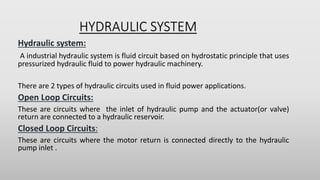
  • 1. HYDRAULIC SYSTEM Hydraulic system: A industrial hydraulic system is fluid circuit based on hydrostatic principle that uses pressurized hydraulic fluid to power hydraulic machinery. There are 2 types of hydraulic circuits used in fluid power applications. Open Loop Circuits: These are circuits where the inlet of hydraulic pump and the actuator(or valve) return are connected to a hydraulic reservoir. Closed Loop Circuits: These are circuits where the motor return is connected directly to the hydraulic pump inlet .
  • 2. • Hydraulic system installed in gasification unit is Open Loop Circuits supplied by M/s Rexroth. • Hydraulic system in unit-3 is divided into 3 verticals 1.Power pack 2.Working field circuit 3.Recirculation unit
  • 3. Hydraulic oil reservoir Main header pump Discharge filter & NRV Field working circuit Main header accumulator Line accumulator filter Bearing flushing line Return line PSV Power pack Drain line
  • 4. Hydraulic reservoir  Tank capacity-6000 lit  Material- Stainless steel with tank inside Epoxy coated.  Design for atmospheric pressure & temp 20-70o c  Reservoir divide with main pump suction chamber & Return line chamber.  Oil chambers are provided by 4o slope from centre to out word for easy removal of dirt particle.  Reservoir Fitted with two breather for filtration & dehumidification of intake air.
  • 5.  Reservoir maximum & minimum oil level >68%– warning HH >65%– warning H > 33%– warning L >24%– warning LL  Reservoir maximum & minimum oil Temperature >62oc– warning HH >60oc – warning H
  • 6. HYDRAULIC OIL  HFDR-46 synthetic oil is used in our hydraulic system. Properties of HFDR-46  Fire resistant hydraulic fluid based on selected phosphate esters Good lubrication performance and anti-wear properties. Excellent oxidation stability. Prevention of foaming and very quick air release
  • 7. Main Hydraulic pump • 4 no's of Multiaxial piston pump installed considering 3 no's pump in continuous operation & 1 pump for standby condition.  Type-A4VSO180 Variable displacement type pump.  Capacity-223 l/m  discharge pressure-110kg/cm2,  Efficiency-93.5%  Best operating viscosity range 16 to 43 centistoke. Require Minimum Cleanliness level ISO 20/18/15
  • 8. NAS & ISO 4406 interconversion Maximum Contamination Limits (per 100 mL) Size range in microns Approximate ISO 4406 Equivalent NAS 1638 code 5-15 µm 15-25 µm 25-50 µm 50-100 µm Over 100 µm — 00 125 22 4 1 0 — 0 250 44 8 2 0 12/10/7 1 500 89 16 3 1 13/11/8 2 1000 178 32 6 1 14/12/9 3 2000 356 63 11 2 15/13/10 4 4000 712 126 22 4 16/14/11 5 8000 1425 253 45 8 17/15/12 6 16,000 2850 506 90 16 18/16/13 7 32,000 5700 1012 190 32 19/17/14 8 64,000 11,400 2025 360 64 20/18/15 9 128,000 22,800 4050 720 128 21/19/16 10 256,000 45,600 8100 1440 256 22/20/17 11 512,000 91,200 16,200 2880 512 23/21/18 12 1,024,000 182,400 32,400 5760 1020
  • 9. DICHARGE & RETURN LINE FILTER • General: Filter clogging indicators to be evaluated only when fluid temperature is higher than 30o C. • Each discharge line of main pump Fitted with 10 micron filter. > 5 kg/cm2 – warning H > 7 kg/cm2 - warning HH • Return line fitted with 10 micron filter. > 2 kg/cm2 - warning H > 4 kg/cm2 - warning HH
  • 10. ACCUMULATOR SECTION Main accumulator • 2 no's accumulator having each capacity 180 L. • Accumulator fitted with 8 no's (8*75=600 l) of nitrogen cylinder. Line Accumulator • Total 4 no's of line accumulator present at 5 meter & 21 meter • Each capacity 30 litre .
  • 11. WORKING FIELD CIRCUIT Pressure reducing valve solenoid DC Valve Flow control Circuit selection Actuator Mimic panel accumulator Pressure reducing valve Optional Valve
  • 12. PRESSURE REDUCING VALVE • 2 pressure reducing valve in parallel connection (Size-NG20) • General pressure setting 65kg/cm2 & 67kg/cm2 • Extra pressure reducing valve for dv6,dv2,dv4 & ash lock bottom cone. • General pressure setting for reducing valve is 30kg/cm2. SOLENOID OPERATED DC VALVE • we are using 4/2 or 4/3 DC solenoid valve with hydraulic pilot line operated. • Always we have extra solenoid DC valve for avoiding any malpractice situation. FLOW CONTROL • Meter in type flow control are installed in our hydraulic circuit. • Main purpose of this meter in type circuit is velocity control in our actuator.
  • 13. CIRCUIT SELECTION • Each circuit has 2 no's of solenoid operated DC valve. • Out of which we can choose running & isolation of any DC valve by manual ball valve. ACTUATER • In our circuit only linear type actuators are used with different size. • Every actuator Fitted with cushioning for avoiding damage of piston seal & equipment. • Maximum speed of actuator is .2m/sec. • Gasifier area operating actuator hydraulic pressure.
  • 14. Sl no Equipment actuator name Operating pressure 1 Coal feeding chute 65kg/cm2 2 Coal lock top cone 30kg/cm2 3 Coal lock bottom cone 65kg/cm2 4 Ash lock top cone 65kg/cm2 5 Ash lock bottom cone 30kg/cm2 6 DV1 valve 65kg/cm2 7 DV2 valve 30kg/cm2 8 DV5 valve 65kg/cm2 9 DV6 valve 30kg/cm2 10 PV1 valve 65kg/cm2
  • 15. RECIRCULATION PART Hydraulic oil Reservoir Recirculation pump Filtering Unit Cooling unit Main pump bearing flushing line Temp sense bypass line Filling pump NRV
  • 16. RECIRCULATION PUMP • 2no’s of Screw pump(1 running & 1 standby) are used for cooling purpose having capacity 110 l/min. • Working pressure 10kg/cm2 & efficiency 93.5%. • Self priming type screw pump with triple screw. FILLING PUMP • 1 no of Screw pump is used for filling purpose having capacity 13l/ min. • Working pressure 5kg/cm2 & efficiency 93.5%. FILTERING UNIT • We are using 6 micron duplex filter for recirculation unit . • > 2 kg/cm2 - warning H • > 4 kg/cm2 - warning HH
  • 17. COOLING UNIT • We are using shell & tube type Heat exchanger for cooling purpose with 1 stand by condition. • Cooling water flow 100 lit/min at maximum 35ocentigrade. • Cooling water inlet to the heat exchanger control by thermostatically reservoir temperature. Daily pm check list
  • 18. FREQUENT PRBLEMS • Leakage from hydraulic hose. • Looseness of QRC • Malfunction of solenoid DC valve. • Increase of hydraulic oil temperature. MAJOR FAILURE • Recirculation pump seal failure. • Main header pump flow problem.
  • 19.