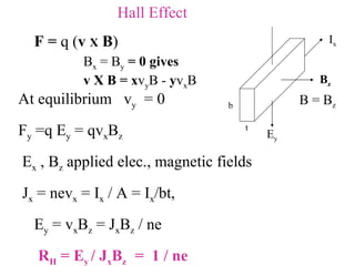
1. Hall Effect F = q ( v X B ) At equilibrium v y = 0 F y =q E y = qv x B z E x , B z applied elec., magnetic fields J x = nev x = I x / A = I x /bt, E y = v x B z = J x B z / ne R H = E y / J x B z = 1 / ne B z E y I x b t B = B z B x = B y = 0 gives v X B = x v y B - y v x B
2. In doped semiconductors of n-type (or p-type ) n e (or n h ) dominates . Conductivity = n e e e + n h e h Measured Hall voltage V y = E y b = R H J x B z b = R H I x B z /t
5. Contributions to Measured V y V y = V H + V th + V m 1 Tesla = 10 4 Gauss = 1 Volt sec / m 2 V H - Hall Voltage V th - Thermo emf V m – magneto-resistance contribution
6. Measurements done Mag Current I B (A) Mag. Field B (kG) V y + V y - V R + V R - R’ (B) Mag Current - I B (A) Mag. Field -B (kG) V y + V y - V R + V R - R’ (-B)
7. Corrections to be applied V th - depends on the temp. gradient along y- direction and is independent of current I x direction V m - depends on the magnitude of magnetic field and the magneto-resistance (R m = R /R . B) of the sample and is independent of the direction of B Changing the direction of I from +x to -x V y + (B, I) = R H BI / t + V th + I R m V y - (B, -I) = - R H BI / t + V th - I R m (V y + - V y - ) / (I x + - I x - ) gives ( R H B/ t) + R m = R’ (B) this eliminates V th contribution.
8. To eliminate the contribution due to R m The direction of magnetic field is changed to ( -B) And V y + (-B, I) = -R H BI + V th + I R m V y - (-B, -I) = R H BI + V th - I R m (V y + - V y - ) / (I x + - I x - ) gives (-R H B/ t) + R m = R’ (-B) R = R’(B) – R’(-B) = 2 R H B / t = R H (B z + + B z - ) / t Slope = 2 R H / t B R
9. Procedure : 1. Connect up the circuit as shown in figure 2. Set 3 mA current through the sample. 3. Keep the sample outside the electromagent (H = 0) and check for Offset Voltage between C & D. Make sure it is < 1 to 5 mV. 4. Fix a small current of nearly 2 Amperes through the electromagnet coils. Check for the direction of field, using a Bar magnet 5. Measure the polarities of voltages between (a) A and B; (b) C and D and determine the direction of Current and Hall Voltage. 6. Determine the sign of charge carriers 7. Adjust the orientation of Gaussmeter probe to read maximum value of field on display, for a given magnet current. 8. Set the magnet current to 7.5 Amps and note the voltage drops across the Hall terminals (V y ) and across the series resistor, R in the circuit (V R ). 9. The DPDT switch enables change of direction of current in the circuit. Note the following readings: A B C D x y + - B z n - type