SlideShare a Scribd company logo
1 of 44
Rectangular Waveguides
Dr. S. Cruz-Pol
INEL 6216
University of Puerto Rico
Mayagüez
Waveguide components
Figures from: www.microwaves101.com/encyclopedia/waveguide.cfm
Rectangular waveguide Waveguide to coax adapter
E-teeWaveguide bends
More waveguides
http://www.tallguide.com/Waveguidelinearity.html
Uses
 To reduce attenuation loss
 High frequencies
 High power
 Can operate only above certain
frequencies
 Acts as a High-pass filter
 Normally circular or rectangular
 We will assume lossless rectangular
Rectangular WG
 Need to find the fields
components of the
em wave inside the
waveguide
 Ez Hz Ex Hx Ey Hy
 We’ll find that
waveguides don’t
support TEM waves
http://www.ee.surrey.ac.uk/Personal/D.Jefferies/wguide.html
Rectangular Waveguides:
Fields inside
Using phasors & assuming waveguide
filled with
 lossless dielectric material and
 walls of perfect conductor,
the wave inside should obey…
ck
HkH
EkE
µεω22
22
22
where
0
0
=
=+∇
=+∇
Then applying on the z-component…
2
2
2
2
2
2
2
2
:obtainwewherefrom
)()()(),,(
:VariablesofSeparationofmethodbySolving
0
k
Z
Z
Y
Y
X
X
zZyYxXzyxE
Ek
z
E
y
E
x
E
''''''
z
z
zzz
−=++
=
=+
∂
∂
+
∂
∂
+
∂
∂
022
=+∇ zz EkE
Fields inside the waveguide
0
0
0
:sexpressionin theresultswhich
2
2
2
2222
2
=−
=+
=+
−=+−−
−=++
ZZ
YkY
XkX
kkk
k
Z
Z
Y
Y
X
X
''
y
''
x
''
yx
''''''
γ
γ
zz
yy
xx
ececzZ
ykcykcY(y)
xkcxkcX(x)
γγ −
+=
+=
+=
65
43
21
)(
sincos
sincos
22222
yx kkkh +=+= γ
Substituting
zz
yy
xx
ececzZ
ykcykcY(y)
xkcxkcX(x)
γγ −
+=
+=
+=
65
43
21
)(
sincos
sincos
)()()(),,( zZyYxXzyxEz =
( )( )( )
( )( )
( )( ) z
yyxxz
z
yyxxz
zz
yyxxz
eykBykBxkBxkBH
eykAykAxkAxkAE
z
ececykcykcxkcxkcE
γ
γ
γγ
−
−
−
++=
++=
+
+++=
sincossincos
,fieldmagneticfor theSimilarly
sincossincos
:direction-intravelingwaveat thelookingonlyIf
sincossincos
4321
4321
654321
Other components
From Faraday and Ampere Laws we can find the
remaining four components:
22222
22
22
22
22
yx
zz
y
zz
x
zz
y
zz
x
kkkh
where
y
H
hx
E
h
j
H
x
H
hy
E
h
j
H
x
H
h
j
y
E
h
E
y
H
h
j
x
E
h
E
+=+=
∂
∂
−
∂
∂
−=
∂
∂
−
∂
∂
=
∂
∂
−
∂
∂
−=
∂
∂
−
∂
∂
−=
γ
γωε
γωε
ωµγ
ωµγ
*So once we know
Ez and Hz, we can
find all the other
fields.
Modes of propagation
From these equations we can conclude:
 TEM (Ez=Hz=0) can’t propagate.
 TE (Ez=0) transverse electric
 In TE mode, the electric lines of flux are
perpendicular to the axis of the waveguide
 TM (Hz=0) transverse magnetic, Ez exists
 In TM mode, the magnetic lines of flux are
perpendicular to the axis of the waveguide.
 HE hybrid modes in which all components
exists
TM Mode
 Boundary
conditions: ,axE
,byE
z
z
0at0
0at0
==
==
Figure from: www.ee.bilkent.edu.tr/~microwave/programs/magnetic/rect/info.htm
( )( ) z
yyxxz eykAykAxkAxkAE γ−
++= sincossincos 4321
( )( ) zj
yxz eykxkAAE β−
= sinsin42
From these, we conclude:
X(x) is in the form of sin kxx,
where kx=mπ/a, m=1,2,3,…
Y(y) is in the form of sin kyy,
where ky=nπ/b, n=1,2,3,…
So the solution for Ez(x,y,z) is
TM Mode
 Substituting
22
2
sinsin






+





=












= −
b
n
a
m
h
where
ey
b
n
x
a
m
EE zj
oz
ππ
ππ β
22
k+= γ
TMmn
 Other components are
x
E
h
j
H
y
E
h
j
H
y
E
h
E
x
E
h
E
z
y
z
x
z
y
z
x
∂
∂
−=
∂
∂
=
∂
∂
−=
∂
∂
−=
2
2
2
2
ωε
ωε
γ
γ
z
oy
z
ox
z
oy
z
ox
e
b
yn
a
xm
E
a
m
h
j
H
e
b
yn
a
xm
E
b
n
h
j
H
e
b
yn
a
xm
E
b
n
h
E
e
b
yn
a
xm
E
a
m
h
E
γ
γ
γ
γ
πππωε
πππωε
πππγ
πππγ
−
−
−
−


















−=


















=


















−=


















−=
sincos
cossin
cossin
sincos
2
2
2
2
0
sinsin
=












= −
z
zj
oz
H
ey
b
n
x
a
m
EE βππ
TM modes
 The m and n represent the mode of propagation
and indicates the number of variations of the
field in the x and y directions
 Note that for the TM mode, if n or m is zero, all
fields are zero.
 See applet by Paul Falstad
http://www.falstad.com/embox/guide.html
TM Cutoff
 The cutoff frequency occurs when
 Evanescent:
 Means no propagation, everything is attenuated
 Propagation:
 This is the case we are interested since is when the wave is allowed to
travel through the guide.
( )
µεω
ππ
γ
2
22
222
−





+





=
−+=
b
n
a
m
kkk yx
22
22
2
1
2
1
or
0thenWhen






+





=
=+=





+





=
b
n
a
m
f
j
b
n
a
m
c
c
ππ
µεπ
βαγ
ππ
µεω
0andWhen
22
2
==





+





< βαγ
ππ
µεω
b
n
a
m
0andWhen
22
2
==





+





> αβγ
ππ
µεω j
b
n
a
m
Cutoff
 The cutoff frequency is the frequency
below which attenuation occurs and above
which propagation takes place. (High Pass)
 The phase constant becomes
222
2
1' 





−=





−





−=
f
f
b
n
a
m c
β
ππ
µεωβ
22
2
'






+





=
b
n
a
mu
f mnc
fc,mn
attenuation Propagation
of mode mn
Phase velocity and impedance
 The phase velocity is defined as
 And the intrinsic impedance of the mode
is
f
u
u
p
p ===
β
π
λ
β
ω 2
'
2
1' 





−=−==
f
f
H
E
H
E c
x
y
y
x
TM ηη
Summary of TM modes
Wave in the dielectric
medium
Inside the waveguide
εµη /'=
µεωωβ == '/' u
2
1' 





−=
f
fc
TM ηη
2
1
'






−
=
f
fc
λ
λ
βω
β
ω
/
1'
2
=






−
=
f
f
u
c
p
2
1' 





−=
f
fc
ββ
fu /''=λ
µελβω /1'/' === fu
Related example of how fields look:
Parallel plate waveguide - TM modes





 π
=
a
xm
sinAEz
( )ztj
e β−ω
0 a x
m = 1
m = 2
m = 3
xz a
Ez
TE Mode
 Boundary
conditions: ,axE
,byE
y
x
0at0
0at0
==
==
Figure from: www.ee.bilkent.edu.tr/~microwave/programs/magnetic/rect/info.htm
( )( ) zj
yxz eykxkBBH β−
= coscos31
From these, we conclude:
X(x) is in the form of cos kxx,
where kx=mπ/a, m=0,1,2,3,…
Y(y) is in the form of cos kyy,
where ky=nπ/b, n=0,1,2,3,…
So the solution for Ez(x,y,z) is
( )( ) z
yyxxz eykBykBxkBxkBH γ−
++= sincossincos 4321
TE Mode
 Substituting
 Note that n and m cannot be both zero
because the fields will all be zero.
22
2
againwhere
coscos






+





=












= −
b
n
a
m
h
ey
b
n
a
xm
HH zj
oz
ππ
ππ β
TEmn
 Other components are
z
oy
z
ox
z
oy
z
ox
e
b
yn
a
xm
H
b
n
h
j
H
e
b
yn
a
xm
H
a
m
h
j
H
e
b
yn
a
xm
H
a
m
h
j
E
e
b
yn
a
xm
H
b
n
h
j
E
γ
γ
γ
γ
πππβ
πππβ
πππωµ
πππωµ
−
−
−
−


















=


















=


















−=


















=
sincos
cossin
cossin
sincos
2
2
2
2
0
coscos
=












= −
z
zj
oz
E
ey
b
n
x
a
m
HH βππ
y
H
h
H
x
H
h
H
x
H
h
j
E
y
H
h
j
E
z
y
z
x
z
y
z
x
∂
∂
−=
∂
∂
−=
∂
∂
−=
∂
∂
−=
2
2
2
2
γ
γ
ωµ
ωµ
Cutoff
 The cutoff frequency is the same
expression as for the TM mode
 But the lowest attainable frequencies are
lowest because here n or m can be zero.
22
2
'






+





=
b
n
a
mu
f mnc
fc,mn
attenuation Propagation
of mode mn
Dominant Mode
 The dominant mode is the mode with
lowest cutoff frequency.
 It’s always TE10
 The order of the next modes change
depending on the dimensions of the
guide.
Summary of TE modes
Wave in the dielectric
medium
Inside the waveguide
εµη /'=
µεωωβ == '/' u
2
1
'






−
=
f
fc
TE
η
η
2
1
'






−
=
f
fc
λ
λ
βω
β
ω
/
1'
2
=






−
=
f
f
u
c
p
2
1' 





−=
f
fc
ββ
fu /''=λ
µελβω /1'/' === fu
Variation of wave impedance
 Wave impedance varies with
frequency and mode
ηTE
ηTM
η’
η
0 fc,mn
Example:
Consider a length of air-filled copper X-band
waveguide, with dimensions a=2.286cm,
b=1.016cm operating at 10GHz. Find the
cutoff frequencies of all possible propagating
modes.
Solution:
 From the formula for the cut-off frequency
22
2
'






+





=
b
n
a
mu
f mnc
Example
An air-filled 5-by 2-cm waveguide has
at 15GHz
 What mode is being propagated?
 Find β
 Determine Ey/Ex
( ) ( ) V/m50sin40sin20 zj
z eyxE β
ππ −
=
Group velocity, ug
 Is the velocity at which
the energy travels.
 It is always less than u’






=











−=
∂∂
=
s
m
f
f
uu c
g
rad/m
rad/s
1'
/
1
2
ωβ
( )2
'uuu gp =
z
oy e
a
xm
H
ah
j
E γππωµ −












−= sin2
http://www.tpub.com/content/et/14092/css/14092_71.htm
Group Velocity
 As frequency is increased,
the group velocity increases.
Power transmission
 The average Poynting vector for the waveguide
fields is
 where η = ηTE or ηTM depending on the mode
[ ] [ ]
z
EE
HEHEHE
yx
xyyxave
ˆ
2
Re
2
1
Re
2
1
22
***
η
+
=
−=×=P
∫ ∫∫ = =
+
=⋅=
a
x
b
y
yx
aveave dxdy
EE
dSP
0 0
22
2η
P
[W/m2
]
[W]
Attenuation in Lossy
waveguide
 When dielectric inside guide is lossy, and walls
are not perfect conductors, power is lost as it
travels along guide.
 The loss power is
 Where α=αc+αd are the attenuation due to ohmic
(conduction) and dielectric losses
 Usually αc >> αd
z
oave ePP α2−
=
ave
ave
L P
dz
dP
P α2=−=
Attenuation for TE10
 Dielectric attenuation, Np/m
 Conductor attenuation, Np/m
2
12
'






−
−=
f
fc
d
ση
α














+






−
−=
2
10,
2
10,
5.0
1'
2
f
f
a
b
f
f
b
R c
c
s
c
η
α
Dielectric
conductivity!
Waveguide Cavities
 Cavities, or resonators, are
used for storing energy
 Used in klystron tubes,
band-pass filters and
frequency meters
 It’s equivalent to a RLC
circuit at high frequency
 Their shape is that of a
cavity, either cylindrical or
cubical.
Cavity TM Mode to z
:obtainwewherefrom
)()()(),,(
:VariablesofSeparationbySolving
zZyYxXzyxEz =
zkczkczZ
ykcykcY(y)
xkcxkcX(x)
zz
yy
xx
sincos)(
sincos
sincos
65
43
21
+=
+=
+=
2222
zyx kkkkwhere ++=
TMmnp Boundary Conditions
,czEE
,axE
,byE
xy
z
z
0at,0
0at0
0at0
===
==
==
From these, we conclude:
kx=mπ/a
ky=nπ/b
kz=pπ/c
where c is the dimension in z-axis
µεω
πππ
πππ
2
222
2
sinsinsin
=





+





+





=


















=
c
p
b
n
a
m
k
where
c
zp
b
yn
a
xm
EE oz c
Resonant frequency
 The resonant frequency is the same
for TM or TE modes, except that the
lowest-order TM is TM111 and the
lowest-order in TE is TE101.
222
2
'






+





+





=
c
p
b
n
a
mu
fr
Cavity TE Mode to z
:obtainwewherefrom
)()()(),,(
:VariablesofSeparationbySolving
zZyYxXzyxHz =
zkczkczZ
ykcykcY(y)
xkcxkcX(x)
zz
yy
xx
sincos)(
sincos
sincos
65
43
21
+=
+=
+=
2222
zyx kkkkwhere ++=
TEmnp Boundary Conditions
,byE
,axE
,czH
x
y
z
0at,0
0at0
0at0
==
==
==
From these, we conclude:
kx=mπ/a
ky=nπ/b
kz=pπ/c
where c is the dimension in z-axis


















=
c
yp
b
yn
a
xm
HH oz
πππ
sincoscos
c
Quality Factor, Q
 The cavity has walls with finite
conductivity and is therefore losing
stored energy.
 The quality factor, Q, characterized the
loss and also the bandwidth of the
cavity resonator.
 Dielectric cavities are used for
resonators, amplifiers and oscillators at
microwave frequencies.
A dielectric resonator antenna
with a cap for measuring the
radiation efficiency
Univ. of Mississippi
Quality Factor, Q
 Is defined as
( )
( ) ( )[ ]2233
22
101
2
TEmodedominantFor the
101
caaccab
abcca
QTE
+++
+
=
δ cof
where
σµπ
δ
101
1
=
LP
W
latione of oscily per cyclloss energ
storedge energyTime avera
πQ
π2
2
=
=
Example
For a cavity of dimensions; 3cm x 2cm x 7cm filled with
air and made of copper (σc=5.8 x 10⁷
)
 Find the resonant frequency and the quality factor
for the dominant mode.
Answer:
GHzfr 44.5
7
1
2
0
3
1
2
103
22210
=





+





+




⋅
=
6
9
106.1
)1044.5(
1 −
⋅=
⋅
=
coσµ
δ
( )
( ) ( )[ ] 378,568
73737322
72373
2233
22
101
=
+⋅++⋅
⋅⋅+
=
δ
TEQ
GHzfr 9
7
0
2
1
3
1
2
103
22210
110 =





+





+




⋅
=

More Related Content

What's hot

Chap 4 (large scale propagation)
Chap 4 (large scale propagation)Chap 4 (large scale propagation)
Chap 4 (large scale propagation)
asadkhan1327
 
Double Side band Suppressed carrier (DSB-SC) Modulation and Demodulation.
 Double Side band Suppressed carrier (DSB-SC) Modulation and Demodulation. Double Side band Suppressed carrier (DSB-SC) Modulation and Demodulation.
Double Side band Suppressed carrier (DSB-SC) Modulation and Demodulation.
SAiFul IslAm
 

What's hot (20)

Microwave measurements in detail
Microwave measurements in detailMicrowave measurements in detail
Microwave measurements in detail
 
Properties of dft
Properties of dftProperties of dft
Properties of dft
 
Chap 4 (large scale propagation)
Chap 4 (large scale propagation)Chap 4 (large scale propagation)
Chap 4 (large scale propagation)
 
Microwave waveguides 1st 1
Microwave waveguides 1st 1Microwave waveguides 1st 1
Microwave waveguides 1st 1
 
Cavity resonator
Cavity resonatorCavity resonator
Cavity resonator
 
Microwave devices
Microwave devicesMicrowave devices
Microwave devices
 
Short Channel Effect In MOSFET
Short Channel Effect In MOSFETShort Channel Effect In MOSFET
Short Channel Effect In MOSFET
 
Pll ppt
Pll pptPll ppt
Pll ppt
 
VLSI
VLSIVLSI
VLSI
 
Waveguide
WaveguideWaveguide
Waveguide
 
Amplitude modulation & demodulation
Amplitude modulation & demodulation Amplitude modulation & demodulation
Amplitude modulation & demodulation
 
Unit 3- OPTICAL SOURCES AND DETECTORS
Unit 3- OPTICAL SOURCES AND DETECTORS Unit 3- OPTICAL SOURCES AND DETECTORS
Unit 3- OPTICAL SOURCES AND DETECTORS
 
Nyquist criterion for distortion less baseband binary channel
Nyquist criterion for distortion less baseband binary channelNyquist criterion for distortion less baseband binary channel
Nyquist criterion for distortion less baseband binary channel
 
5. 2 ray propagation model part 1
5. 2 ray propagation model   part 15. 2 ray propagation model   part 1
5. 2 ray propagation model part 1
 
DSP_2018_FOEHU - Lec 07 - IIR Filter Design
DSP_2018_FOEHU - Lec 07 - IIR Filter DesignDSP_2018_FOEHU - Lec 07 - IIR Filter Design
DSP_2018_FOEHU - Lec 07 - IIR Filter Design
 
Gunn Diode
Gunn Diode Gunn Diode
Gunn Diode
 
Delta modulation
Delta modulationDelta modulation
Delta modulation
 
EC8562 DSP Viva Questions
EC8562 DSP Viva Questions EC8562 DSP Viva Questions
EC8562 DSP Viva Questions
 
Double Side band Suppressed carrier (DSB-SC) Modulation and Demodulation.
 Double Side band Suppressed carrier (DSB-SC) Modulation and Demodulation. Double Side band Suppressed carrier (DSB-SC) Modulation and Demodulation.
Double Side band Suppressed carrier (DSB-SC) Modulation and Demodulation.
 
Photo detector noise
Photo detector noisePhoto detector noise
Photo detector noise
 

Viewers also liked

Waveguide presentation
Waveguide presentationWaveguide presentation
Waveguide presentation
Syed Umar
 
Microwave- directional coupler paramets & applications
Microwave- directional coupler paramets & applicationsMicrowave- directional coupler paramets & applications
Microwave- directional coupler paramets & applications
JETISH
 
Microwave Devices Lecture11
Microwave Devices Lecture11Microwave Devices Lecture11
Microwave Devices Lecture11
Amr Al-Awamry
 

Viewers also liked (20)

Transmission lines, Waveguide, Antennas
Transmission lines, Waveguide, AntennasTransmission lines, Waveguide, Antennas
Transmission lines, Waveguide, Antennas
 
Waveguide presentation
Waveguide presentationWaveguide presentation
Waveguide presentation
 
Waveguides
WaveguidesWaveguides
Waveguides
 
Waveguide for Microwave Communication
Waveguide for Microwave CommunicationWaveguide for Microwave Communication
Waveguide for Microwave Communication
 
Waveguide
WaveguideWaveguide
Waveguide
 
Mwr ppt priyanka
Mwr ppt priyankaMwr ppt priyanka
Mwr ppt priyanka
 
Waveguides12
Waveguides12Waveguides12
Waveguides12
 
Ec 55 transmission lines and waveguides b
Ec 55 transmission lines and waveguides bEc 55 transmission lines and waveguides b
Ec 55 transmission lines and waveguides b
 
Microwave- directional coupler paramets & applications
Microwave- directional coupler paramets & applicationsMicrowave- directional coupler paramets & applications
Microwave- directional coupler paramets & applications
 
Waveguides
WaveguidesWaveguides
Waveguides
 
Unit iii mirowave passive components
Unit iii mirowave passive componentsUnit iii mirowave passive components
Unit iii mirowave passive components
 
Seminar on ''Magic tee" by kazi md saidur rahaman
Seminar on ''Magic tee"  by kazi md saidur rahamanSeminar on ''Magic tee"  by kazi md saidur rahaman
Seminar on ''Magic tee" by kazi md saidur rahaman
 
Microwave Coupler
Microwave CouplerMicrowave Coupler
Microwave Coupler
 
Microwaves Applications
Microwaves ApplicationsMicrowaves Applications
Microwaves Applications
 
What is Optical fiber ?
What is Optical fiber ?What is Optical fiber ?
What is Optical fiber ?
 
Microwave Devices Lecture11
Microwave Devices Lecture11Microwave Devices Lecture11
Microwave Devices Lecture11
 
Mixers
MixersMixers
Mixers
 
waveguid
waveguidwaveguid
waveguid
 
Chapter 2a
Chapter 2aChapter 2a
Chapter 2a
 
RF circuit design using ADS
RF circuit design using ADSRF circuit design using ADS
RF circuit design using ADS
 

Similar to Rectangular waveguides

4 analysis of laminates
4 analysis of laminates4 analysis of laminates
4 analysis of laminates
Madi Na
 
TwoLevelMedium
TwoLevelMediumTwoLevelMedium
TwoLevelMedium
John Paul
 
Efficient mode-matching analysis of 2-D scattering by periodic array of circu...
Efficient mode-matching analysis of 2-D scattering by periodic array of circu...Efficient mode-matching analysis of 2-D scattering by periodic array of circu...
Efficient mode-matching analysis of 2-D scattering by periodic array of circu...
Yong Heui Cho
 

Similar to Rectangular waveguides (20)

Microwave PPT.ppt
Microwave PPT.pptMicrowave PPT.ppt
Microwave PPT.ppt
 
Lect1
Lect1Lect1
Lect1
 
EM_Theory.pdf
EM_Theory.pdfEM_Theory.pdf
EM_Theory.pdf
 
wave_equation
wave_equationwave_equation
wave_equation
 
Introduction to Diffusion Monte Carlo
Introduction to Diffusion Monte CarloIntroduction to Diffusion Monte Carlo
Introduction to Diffusion Monte Carlo
 
finite element method for waveguide
finite element method for waveguidefinite element method for waveguide
finite element method for waveguide
 
Anuj 10mar2016
Anuj 10mar2016Anuj 10mar2016
Anuj 10mar2016
 
4 analysis of laminates
4 analysis of laminates4 analysis of laminates
4 analysis of laminates
 
Ph 101-9 QUANTUM MACHANICS
Ph 101-9 QUANTUM MACHANICSPh 101-9 QUANTUM MACHANICS
Ph 101-9 QUANTUM MACHANICS
 
ch09.pdf
ch09.pdfch09.pdf
ch09.pdf
 
TwoLevelMedium
TwoLevelMediumTwoLevelMedium
TwoLevelMedium
 
Electromagnetic.pdf
Electromagnetic.pdfElectromagnetic.pdf
Electromagnetic.pdf
 
Physical Chemistry Assignment Help
Physical Chemistry Assignment HelpPhysical Chemistry Assignment Help
Physical Chemistry Assignment Help
 
Efficient mode-matching analysis of 2-D scattering by periodic array of circu...
Efficient mode-matching analysis of 2-D scattering by periodic array of circu...Efficient mode-matching analysis of 2-D scattering by periodic array of circu...
Efficient mode-matching analysis of 2-D scattering by periodic array of circu...
 
physics-of-vibration-and-waves-solutions-pain
 physics-of-vibration-and-waves-solutions-pain physics-of-vibration-and-waves-solutions-pain
physics-of-vibration-and-waves-solutions-pain
 
Wave diffraction
Wave diffractionWave diffraction
Wave diffraction
 
Solutions modern particlephysics
Solutions modern particlephysicsSolutions modern particlephysics
Solutions modern particlephysics
 
Talk at SciCADE2013 about "Accelerated Multiple Precision ODE solver base on ...
Talk at SciCADE2013 about "Accelerated Multiple Precision ODE solver base on ...Talk at SciCADE2013 about "Accelerated Multiple Precision ODE solver base on ...
Talk at SciCADE2013 about "Accelerated Multiple Precision ODE solver base on ...
 
Mcrowave and Radar engineering
Mcrowave and Radar engineeringMcrowave and Radar engineering
Mcrowave and Radar engineering
 
Capitulo 12, 7ma edición
Capitulo 12, 7ma ediciónCapitulo 12, 7ma edición
Capitulo 12, 7ma edición
 

Recently uploaded

Integrated Test Rig For HTFE-25 - Neometrix
Integrated Test Rig For HTFE-25 - NeometrixIntegrated Test Rig For HTFE-25 - Neometrix
Integrated Test Rig For HTFE-25 - Neometrix
Neometrix_Engineering_Pvt_Ltd
 
Call Girls in Ramesh Nagar Delhi 💯 Call Us 🔝9953056974 🔝 Escort Service
Call Girls in Ramesh Nagar Delhi 💯 Call Us 🔝9953056974 🔝 Escort ServiceCall Girls in Ramesh Nagar Delhi 💯 Call Us 🔝9953056974 🔝 Escort Service
Call Girls in Ramesh Nagar Delhi 💯 Call Us 🔝9953056974 🔝 Escort Service
9953056974 Low Rate Call Girls In Saket, Delhi NCR
 
Cara Menggugurkan Sperma Yang Masuk Rahim Biyar Tidak Hamil
Cara Menggugurkan Sperma Yang Masuk Rahim Biyar Tidak HamilCara Menggugurkan Sperma Yang Masuk Rahim Biyar Tidak Hamil
Cara Menggugurkan Sperma Yang Masuk Rahim Biyar Tidak Hamil
Cara Menggugurkan Kandungan 087776558899
 
Call Now ≽ 9953056974 ≼🔝 Call Girls In New Ashok Nagar ≼🔝 Delhi door step de...
Call Now ≽ 9953056974 ≼🔝 Call Girls In New Ashok Nagar  ≼🔝 Delhi door step de...Call Now ≽ 9953056974 ≼🔝 Call Girls In New Ashok Nagar  ≼🔝 Delhi door step de...
Call Now ≽ 9953056974 ≼🔝 Call Girls In New Ashok Nagar ≼🔝 Delhi door step de...
9953056974 Low Rate Call Girls In Saket, Delhi NCR
 
FULL ENJOY Call Girls In Mahipalpur Delhi Contact Us 8377877756
FULL ENJOY Call Girls In Mahipalpur Delhi Contact Us 8377877756FULL ENJOY Call Girls In Mahipalpur Delhi Contact Us 8377877756
FULL ENJOY Call Girls In Mahipalpur Delhi Contact Us 8377877756
dollysharma2066
 

Recently uploaded (20)

Bhosari ( Call Girls ) Pune 6297143586 Hot Model With Sexy Bhabi Ready For ...
Bhosari ( Call Girls ) Pune  6297143586  Hot Model With Sexy Bhabi Ready For ...Bhosari ( Call Girls ) Pune  6297143586  Hot Model With Sexy Bhabi Ready For ...
Bhosari ( Call Girls ) Pune 6297143586 Hot Model With Sexy Bhabi Ready For ...
 
Water Industry Process Automation & Control Monthly - April 2024
Water Industry Process Automation & Control Monthly - April 2024Water Industry Process Automation & Control Monthly - April 2024
Water Industry Process Automation & Control Monthly - April 2024
 
Minimum and Maximum Modes of microprocessor 8086
Minimum and Maximum Modes of microprocessor 8086Minimum and Maximum Modes of microprocessor 8086
Minimum and Maximum Modes of microprocessor 8086
 
Integrated Test Rig For HTFE-25 - Neometrix
Integrated Test Rig For HTFE-25 - NeometrixIntegrated Test Rig For HTFE-25 - Neometrix
Integrated Test Rig For HTFE-25 - Neometrix
 
ONLINE FOOD ORDER SYSTEM PROJECT REPORT.pdf
ONLINE FOOD ORDER SYSTEM PROJECT REPORT.pdfONLINE FOOD ORDER SYSTEM PROJECT REPORT.pdf
ONLINE FOOD ORDER SYSTEM PROJECT REPORT.pdf
 
22-prompt engineering noted slide shown.pdf
22-prompt engineering noted slide shown.pdf22-prompt engineering noted slide shown.pdf
22-prompt engineering noted slide shown.pdf
 
Call Girls Pimpri Chinchwad Call Me 7737669865 Budget Friendly No Advance Boo...
Call Girls Pimpri Chinchwad Call Me 7737669865 Budget Friendly No Advance Boo...Call Girls Pimpri Chinchwad Call Me 7737669865 Budget Friendly No Advance Boo...
Call Girls Pimpri Chinchwad Call Me 7737669865 Budget Friendly No Advance Boo...
 
Call Girls in Ramesh Nagar Delhi 💯 Call Us 🔝9953056974 🔝 Escort Service
Call Girls in Ramesh Nagar Delhi 💯 Call Us 🔝9953056974 🔝 Escort ServiceCall Girls in Ramesh Nagar Delhi 💯 Call Us 🔝9953056974 🔝 Escort Service
Call Girls in Ramesh Nagar Delhi 💯 Call Us 🔝9953056974 🔝 Escort Service
 
UNIT - IV - Air Compressors and its Performance
UNIT - IV - Air Compressors and its PerformanceUNIT - IV - Air Compressors and its Performance
UNIT - IV - Air Compressors and its Performance
 
data_management_and _data_science_cheat_sheet.pdf
data_management_and _data_science_cheat_sheet.pdfdata_management_and _data_science_cheat_sheet.pdf
data_management_and _data_science_cheat_sheet.pdf
 
Employee leave management system project.
Employee leave management system project.Employee leave management system project.
Employee leave management system project.
 
Generative AI or GenAI technology based PPT
Generative AI or GenAI technology based PPTGenerative AI or GenAI technology based PPT
Generative AI or GenAI technology based PPT
 
Cara Menggugurkan Sperma Yang Masuk Rahim Biyar Tidak Hamil
Cara Menggugurkan Sperma Yang Masuk Rahim Biyar Tidak HamilCara Menggugurkan Sperma Yang Masuk Rahim Biyar Tidak Hamil
Cara Menggugurkan Sperma Yang Masuk Rahim Biyar Tidak Hamil
 
Navigating Complexity: The Role of Trusted Partners and VIAS3D in Dassault Sy...
Navigating Complexity: The Role of Trusted Partners and VIAS3D in Dassault Sy...Navigating Complexity: The Role of Trusted Partners and VIAS3D in Dassault Sy...
Navigating Complexity: The Role of Trusted Partners and VIAS3D in Dassault Sy...
 
(INDIRA) Call Girl Aurangabad Call Now 8617697112 Aurangabad Escorts 24x7
(INDIRA) Call Girl Aurangabad Call Now 8617697112 Aurangabad Escorts 24x7(INDIRA) Call Girl Aurangabad Call Now 8617697112 Aurangabad Escorts 24x7
(INDIRA) Call Girl Aurangabad Call Now 8617697112 Aurangabad Escorts 24x7
 
Thermal Engineering -unit - III & IV.ppt
Thermal Engineering -unit - III & IV.pptThermal Engineering -unit - III & IV.ppt
Thermal Engineering -unit - III & IV.ppt
 
Call Now ≽ 9953056974 ≼🔝 Call Girls In New Ashok Nagar ≼🔝 Delhi door step de...
Call Now ≽ 9953056974 ≼🔝 Call Girls In New Ashok Nagar  ≼🔝 Delhi door step de...Call Now ≽ 9953056974 ≼🔝 Call Girls In New Ashok Nagar  ≼🔝 Delhi door step de...
Call Now ≽ 9953056974 ≼🔝 Call Girls In New Ashok Nagar ≼🔝 Delhi door step de...
 
A Study of Urban Area Plan for Pabna Municipality
A Study of Urban Area Plan for Pabna MunicipalityA Study of Urban Area Plan for Pabna Municipality
A Study of Urban Area Plan for Pabna Municipality
 
FULL ENJOY Call Girls In Mahipalpur Delhi Contact Us 8377877756
FULL ENJOY Call Girls In Mahipalpur Delhi Contact Us 8377877756FULL ENJOY Call Girls In Mahipalpur Delhi Contact Us 8377877756
FULL ENJOY Call Girls In Mahipalpur Delhi Contact Us 8377877756
 
Unit 2- Effective stress & Permeability.pdf
Unit 2- Effective stress & Permeability.pdfUnit 2- Effective stress & Permeability.pdf
Unit 2- Effective stress & Permeability.pdf
 

Rectangular waveguides

  • 1. Rectangular Waveguides Dr. S. Cruz-Pol INEL 6216 University of Puerto Rico Mayagüez
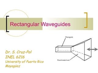
  • 2. Waveguide components Figures from: www.microwaves101.com/encyclopedia/waveguide.cfm Rectangular waveguide Waveguide to coax adapter E-teeWaveguide bends
  • 4. Uses  To reduce attenuation loss  High frequencies  High power  Can operate only above certain frequencies  Acts as a High-pass filter  Normally circular or rectangular  We will assume lossless rectangular
  • 5. Rectangular WG  Need to find the fields components of the em wave inside the waveguide  Ez Hz Ex Hx Ey Hy  We’ll find that waveguides don’t support TEM waves http://www.ee.surrey.ac.uk/Personal/D.Jefferies/wguide.html
  • 6. Rectangular Waveguides: Fields inside Using phasors & assuming waveguide filled with  lossless dielectric material and  walls of perfect conductor, the wave inside should obey… ck HkH EkE µεω22 22 22 where 0 0 = =+∇ =+∇
  • 7. Then applying on the z-component… 2 2 2 2 2 2 2 2 :obtainwewherefrom )()()(),,( :VariablesofSeparationofmethodbySolving 0 k Z Z Y Y X X zZyYxXzyxE Ek z E y E x E '''''' z z zzz −=++ = =+ ∂ ∂ + ∂ ∂ + ∂ ∂ 022 =+∇ zz EkE
  • 8. Fields inside the waveguide 0 0 0 :sexpressionin theresultswhich 2 2 2 2222 2 =− =+ =+ −=+−− −=++ ZZ YkY XkX kkk k Z Z Y Y X X '' y '' x '' yx '''''' γ γ zz yy xx ececzZ ykcykcY(y) xkcxkcX(x) γγ − += += += 65 43 21 )( sincos sincos 22222 yx kkkh +=+= γ
  • 9. Substituting zz yy xx ececzZ ykcykcY(y) xkcxkcX(x) γγ − += += += 65 43 21 )( sincos sincos )()()(),,( zZyYxXzyxEz = ( )( )( ) ( )( ) ( )( ) z yyxxz z yyxxz zz yyxxz eykBykBxkBxkBH eykAykAxkAxkAE z ececykcykcxkcxkcE γ γ γγ − − − ++= ++= + +++= sincossincos ,fieldmagneticfor theSimilarly sincossincos :direction-intravelingwaveat thelookingonlyIf sincossincos 4321 4321 654321
  • 10. Other components From Faraday and Ampere Laws we can find the remaining four components: 22222 22 22 22 22 yx zz y zz x zz y zz x kkkh where y H hx E h j H x H hy E h j H x H h j y E h E y H h j x E h E +=+= ∂ ∂ − ∂ ∂ −= ∂ ∂ − ∂ ∂ = ∂ ∂ − ∂ ∂ −= ∂ ∂ − ∂ ∂ −= γ γωε γωε ωµγ ωµγ *So once we know Ez and Hz, we can find all the other fields.
  • 11. Modes of propagation From these equations we can conclude:  TEM (Ez=Hz=0) can’t propagate.  TE (Ez=0) transverse electric  In TE mode, the electric lines of flux are perpendicular to the axis of the waveguide  TM (Hz=0) transverse magnetic, Ez exists  In TM mode, the magnetic lines of flux are perpendicular to the axis of the waveguide.  HE hybrid modes in which all components exists
  • 12. TM Mode  Boundary conditions: ,axE ,byE z z 0at0 0at0 == == Figure from: www.ee.bilkent.edu.tr/~microwave/programs/magnetic/rect/info.htm ( )( ) z yyxxz eykAykAxkAxkAE γ− ++= sincossincos 4321 ( )( ) zj yxz eykxkAAE β− = sinsin42 From these, we conclude: X(x) is in the form of sin kxx, where kx=mπ/a, m=1,2,3,… Y(y) is in the form of sin kyy, where ky=nπ/b, n=1,2,3,… So the solution for Ez(x,y,z) is
  • 14. TMmn  Other components are x E h j H y E h j H y E h E x E h E z y z x z y z x ∂ ∂ −= ∂ ∂ = ∂ ∂ −= ∂ ∂ −= 2 2 2 2 ωε ωε γ γ z oy z ox z oy z ox e b yn a xm E a m h j H e b yn a xm E b n h j H e b yn a xm E b n h E e b yn a xm E a m h E γ γ γ γ πππωε πππωε πππγ πππγ − − − −                   −=                   =                   −=                   −= sincos cossin cossin sincos 2 2 2 2 0 sinsin =             = − z zj oz H ey b n x a m EE βππ
  • 15. TM modes  The m and n represent the mode of propagation and indicates the number of variations of the field in the x and y directions  Note that for the TM mode, if n or m is zero, all fields are zero.  See applet by Paul Falstad http://www.falstad.com/embox/guide.html
  • 16. TM Cutoff  The cutoff frequency occurs when  Evanescent:  Means no propagation, everything is attenuated  Propagation:  This is the case we are interested since is when the wave is allowed to travel through the guide. ( ) µεω ππ γ 2 22 222 −      +      = −+= b n a m kkk yx 22 22 2 1 2 1 or 0thenWhen       +      = =+=      +      = b n a m f j b n a m c c ππ µεπ βαγ ππ µεω 0andWhen 22 2 ==      +      < βαγ ππ µεω b n a m 0andWhen 22 2 ==      +      > αβγ ππ µεω j b n a m
  • 17. Cutoff  The cutoff frequency is the frequency below which attenuation occurs and above which propagation takes place. (High Pass)  The phase constant becomes 222 2 1'       −=      −      −= f f b n a m c β ππ µεωβ 22 2 '       +      = b n a mu f mnc fc,mn attenuation Propagation of mode mn
  • 18. Phase velocity and impedance  The phase velocity is defined as  And the intrinsic impedance of the mode is f u u p p === β π λ β ω 2 ' 2 1'       −=−== f f H E H E c x y y x TM ηη
  • 19. Summary of TM modes Wave in the dielectric medium Inside the waveguide εµη /'= µεωωβ == '/' u 2 1'       −= f fc TM ηη 2 1 '       − = f fc λ λ βω β ω / 1' 2 =       − = f f u c p 2 1'       −= f fc ββ fu /''=λ µελβω /1'/' === fu
  • 20. Related example of how fields look: Parallel plate waveguide - TM modes       π = a xm sinAEz ( )ztj e β−ω 0 a x m = 1 m = 2 m = 3 xz a Ez
  • 21. TE Mode  Boundary conditions: ,axE ,byE y x 0at0 0at0 == == Figure from: www.ee.bilkent.edu.tr/~microwave/programs/magnetic/rect/info.htm ( )( ) zj yxz eykxkBBH β− = coscos31 From these, we conclude: X(x) is in the form of cos kxx, where kx=mπ/a, m=0,1,2,3,… Y(y) is in the form of cos kyy, where ky=nπ/b, n=0,1,2,3,… So the solution for Ez(x,y,z) is ( )( ) z yyxxz eykBykBxkBxkBH γ− ++= sincossincos 4321
  • 22. TE Mode  Substituting  Note that n and m cannot be both zero because the fields will all be zero. 22 2 againwhere coscos       +      =             = − b n a m h ey b n a xm HH zj oz ππ ππ β
  • 23. TEmn  Other components are z oy z ox z oy z ox e b yn a xm H b n h j H e b yn a xm H a m h j H e b yn a xm H a m h j E e b yn a xm H b n h j E γ γ γ γ πππβ πππβ πππωµ πππωµ − − − −                   =                   =                   −=                   = sincos cossin cossin sincos 2 2 2 2 0 coscos =             = − z zj oz E ey b n x a m HH βππ y H h H x H h H x H h j E y H h j E z y z x z y z x ∂ ∂ −= ∂ ∂ −= ∂ ∂ −= ∂ ∂ −= 2 2 2 2 γ γ ωµ ωµ
  • 24. Cutoff  The cutoff frequency is the same expression as for the TM mode  But the lowest attainable frequencies are lowest because here n or m can be zero. 22 2 '       +      = b n a mu f mnc fc,mn attenuation Propagation of mode mn
  • 25. Dominant Mode  The dominant mode is the mode with lowest cutoff frequency.  It’s always TE10  The order of the next modes change depending on the dimensions of the guide.
  • 26. Summary of TE modes Wave in the dielectric medium Inside the waveguide εµη /'= µεωωβ == '/' u 2 1 '       − = f fc TE η η 2 1 '       − = f fc λ λ βω β ω / 1' 2 =       − = f f u c p 2 1'       −= f fc ββ fu /''=λ µελβω /1'/' === fu
  • 27. Variation of wave impedance  Wave impedance varies with frequency and mode ηTE ηTM η’ η 0 fc,mn
  • 28. Example: Consider a length of air-filled copper X-band waveguide, with dimensions a=2.286cm, b=1.016cm operating at 10GHz. Find the cutoff frequencies of all possible propagating modes. Solution:  From the formula for the cut-off frequency 22 2 '       +      = b n a mu f mnc
  • 29. Example An air-filled 5-by 2-cm waveguide has at 15GHz  What mode is being propagated?  Find β  Determine Ey/Ex ( ) ( ) V/m50sin40sin20 zj z eyxE β ππ − =
  • 30. Group velocity, ug  Is the velocity at which the energy travels.  It is always less than u’       =            −= ∂∂ = s m f f uu c g rad/m rad/s 1' / 1 2 ωβ ( )2 'uuu gp = z oy e a xm H ah j E γππωµ −             −= sin2 http://www.tpub.com/content/et/14092/css/14092_71.htm
  • 31. Group Velocity  As frequency is increased, the group velocity increases.
  • 32. Power transmission  The average Poynting vector for the waveguide fields is  where η = ηTE or ηTM depending on the mode [ ] [ ] z EE HEHEHE yx xyyxave ˆ 2 Re 2 1 Re 2 1 22 *** η + = −=×=P ∫ ∫∫ = = + =⋅= a x b y yx aveave dxdy EE dSP 0 0 22 2η P [W/m2 ] [W]
  • 33. Attenuation in Lossy waveguide  When dielectric inside guide is lossy, and walls are not perfect conductors, power is lost as it travels along guide.  The loss power is  Where α=αc+αd are the attenuation due to ohmic (conduction) and dielectric losses  Usually αc >> αd z oave ePP α2− = ave ave L P dz dP P α2=−=
  • 34. Attenuation for TE10  Dielectric attenuation, Np/m  Conductor attenuation, Np/m 2 12 '       − −= f fc d ση α               +       − −= 2 10, 2 10, 5.0 1' 2 f f a b f f b R c c s c η α Dielectric conductivity!
  • 35. Waveguide Cavities  Cavities, or resonators, are used for storing energy  Used in klystron tubes, band-pass filters and frequency meters  It’s equivalent to a RLC circuit at high frequency  Their shape is that of a cavity, either cylindrical or cubical.
  • 36. Cavity TM Mode to z :obtainwewherefrom )()()(),,( :VariablesofSeparationbySolving zZyYxXzyxEz = zkczkczZ ykcykcY(y) xkcxkcX(x) zz yy xx sincos)( sincos sincos 65 43 21 += += += 2222 zyx kkkkwhere ++=
  • 37. TMmnp Boundary Conditions ,czEE ,axE ,byE xy z z 0at,0 0at0 0at0 === == == From these, we conclude: kx=mπ/a ky=nπ/b kz=pπ/c where c is the dimension in z-axis µεω πππ πππ 2 222 2 sinsinsin =      +      +      =                   = c p b n a m k where c zp b yn a xm EE oz c
  • 38. Resonant frequency  The resonant frequency is the same for TM or TE modes, except that the lowest-order TM is TM111 and the lowest-order in TE is TE101. 222 2 '       +      +      = c p b n a mu fr
  • 39. Cavity TE Mode to z :obtainwewherefrom )()()(),,( :VariablesofSeparationbySolving zZyYxXzyxHz = zkczkczZ ykcykcY(y) xkcxkcX(x) zz yy xx sincos)( sincos sincos 65 43 21 += += += 2222 zyx kkkkwhere ++=
  • 40. TEmnp Boundary Conditions ,byE ,axE ,czH x y z 0at,0 0at0 0at0 == == == From these, we conclude: kx=mπ/a ky=nπ/b kz=pπ/c where c is the dimension in z-axis                   = c yp b yn a xm HH oz πππ sincoscos c
  • 41. Quality Factor, Q  The cavity has walls with finite conductivity and is therefore losing stored energy.  The quality factor, Q, characterized the loss and also the bandwidth of the cavity resonator.  Dielectric cavities are used for resonators, amplifiers and oscillators at microwave frequencies.
  • 42. A dielectric resonator antenna with a cap for measuring the radiation efficiency Univ. of Mississippi
  • 43. Quality Factor, Q  Is defined as ( ) ( ) ( )[ ]2233 22 101 2 TEmodedominantFor the 101 caaccab abcca QTE +++ + = δ cof where σµπ δ 101 1 = LP W latione of oscily per cyclloss energ storedge energyTime avera πQ π2 2 = =
  • 44. Example For a cavity of dimensions; 3cm x 2cm x 7cm filled with air and made of copper (σc=5.8 x 10⁷ )  Find the resonant frequency and the quality factor for the dominant mode. Answer: GHzfr 44.5 7 1 2 0 3 1 2 103 22210 =      +      +     ⋅ = 6 9 106.1 )1044.5( 1 − ⋅= ⋅ = coσµ δ ( ) ( ) ( )[ ] 378,568 73737322 72373 2233 22 101 = +⋅++⋅ ⋅⋅+ = δ TEQ GHzfr 9 7 0 2 1 3 1 2 103 22210 110 =      +      +     ⋅ =