

Recommended
More Related Content
What's hot
What's hot (20)
Similar to Tango
Similar to Tango (20)
Recently uploaded
Recently uploaded (20)
Tango
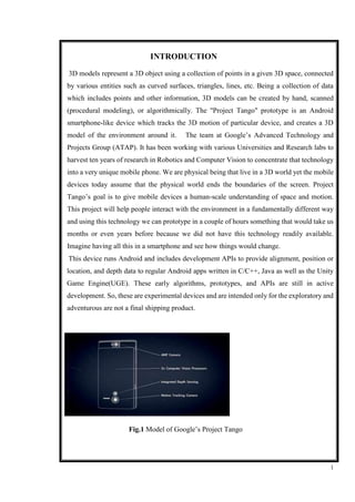
- 1. 1 INTRODUCTION 1 3D models represent a 3D object using a collection of points in a given 3D space, connected by various entities such as curved surfaces, triangles, lines, etc. Being a collection of data which includes points and other information, 3D models can be created by hand, scanned (procedural modeling), or algorithmically. The "Project Tango" prototype is an Android smartphone-like device which tracks the 3D motion of particular device, and creates a 3D model of the environment around it. The team at Google’s Advanced Technology and Projects Group (ATAP). It has been working with various Universities and Research labs to harvest ten years of research in Robotics and Computer Vision to concentrate that technology into a very unique mobile phone. We are physical being that live in a 3D world yet the mobile devices today assume that the physical world ends the boundaries of the screen. Project Tango’s goal is to give mobile devices a human-scale understanding of space and motion. This project will help people interact with the environment in a fundamentally different way and using this technology we can prototype in a couple of hours something that would take us months or even years before because we did not have this technology readily available. Imagine having all this in a smartphone and see how things would change. This device runs Android and includes development APIs to provide alignment, position or location, and depth data to regular Android apps written in C/C++, Java as well as the Unity Game Engine(UGE). These early algorithms, prototypes, and APIs are still in active development. So, these are experimental devices and are intended only for the exploratory and adventurous are not a final shipping product. Fig.1 Model of Google’s Project Tango
- 2. 2 1. Description Project Tango is a prototype phone containing highly customized hardware and software designed to allow the phone to track its motion in full 3D in real-time. The sensors make over a quarter million 3D measurements every single second updating the position and rotation of the phone, blending this data into a single 3D model of the environment. It tracks ones position as one goes around the world and also makes a map of that. It can scan a small section of your room and then are able to generate a little game world in it. It is an open source technology. ATAP has around 200 development kits which has already been distributed among the developers. 2. Overview Google's Project Tango is a smartphone equipped with a variety of cameras and vision sensors that provides a whole new perspective on the world around it. The Tango smartphone can capture a wealth of data never before available to application developers, including depth and object-tracking and instantaneous 3D mapping. And it is almost as powerful and as big as a typical smartphone. It's also available as a high-end Android tablet with 7-inch HD display, 4GB of RAM, 128GB of internal SSD storage and an NVIDIA Tegra K1 graphics chip (the first in the US and second in the world) that features desktop GPU architecture. It also has a distinctive design that consists of an array of cameras and sensors near the top and a couple of subtle grips on the sides. Movidius which is the company that developed some of the technology which has been used in Tango has been working on computer vision technology for the past seven years — it developed the processing chips used in Project Tango, which Google paired with sensors and cameras to give the smartphone the same level of computer vision and tracking that formerly required much larger equipment. The phone is equipped with a standard 4-megapixel camera paired with a special combination of RGB and IR sensor and a lower-resolution image- tracking camera. These combos of image sensors give the smartphone a similar perspective on the world, complete with 3-D awareness and a awareness of depth. They supply
- 3. 3 information to Movidius custom Myriad 1 low-power computer-vision processor, which can then process the data and feed it to apps through a set of APIs. The phone also contains a Motion Tracking camera which is used to keep track of all the motions made by the user. purple is the SoC 3D sensor Prime Sense PSX1200 Capri PS1200, the blue is SPI flash memory Winbond W25Q16CV 16Mbit. Internally, the Myriad 2 consists of 12 128-bit vector processors called Streaming Hybrid Architecture Vector Engines, or SHAVE in general, which run at 60MHz. The Myriad 2 chip gives five times the SHAVE performance of the Myriad 1, and the SIPP engines are 15x to 25x more powerful than the 1st generation chip. The SHAVE engines communicates with more than 20 Streaming Image Processing Pipeline engines, which serve as hardware image processing accelerators. 2.1 Project Tango Developer Overview Project Tango is a platform that uses computer vision to give devices the ability to understand their position relative to the world around them. The Project Tango Tablet Development Kit is an Android device with a wide-angle camera, a depth sensing camera, accurate sensor time stamping, and a software stack that enables application developers to use motion tracking, area learning and depth sensing. Thousands of developers have purchased these developer kits to create experiences to explore physical space around the user, including precise navigation without GPS, windows into virtual 3D worlds, measurement and scanning of spaces, and games that know where they are in the room and what’s around them. You will need a Project Tango Tablet Development Kit in order to run and test any apps you develop. If you do not have a device, you can purchase one from the Google Store. In the meantime, you can familiarize yourself with our documentation and APIs to plan how you might create your Project Tango app
- 4. 4 2.2 Motion tracking overview Motion Tracking means that a Project Tango device can track its own movement and orientation through 3D space. Walk around with a device and move it forward, backward, up, or down, or tilt it in any direction, and it can tell you where it is and which way it's facing. It's similar to how a mouse works, but instead of moving around on a flat surface, the world is your mouse pad. 2.3 Area learning overview Human beings learn to recognize where they are in an environment by noticing the features around them: a doorway, a staircase, the way to the nearest restroom. Project Tango gives your mobile device the same ability. With Motion Tracking alone, the device "sees" the visual features of the area it is moving through but doesn’t "remember" them. With Area Learning turned on, the device not only remembers what it sees, it can also save and recall that information. When you enter a previously saved area, the device uses a process called localization to recognize where you are in the area. This feature opens up a wide range of creative applications. The device also uses Area Learning to improve the accuracy of Motion Tracking. 2.4 Depth Perception overview With depth perception, your device can understand the shape of your surroundings. This lets you create "augmented reality," where virtual objects not only appear to be a part of your actual environment, they can also interact with that environment. One example: you create a virtual character who jumps onto and then skitters across a real-world table top.
- 5. 5 3. Main Challenges The figure above is the motherboard: the red is 2GB LPDDR3 RAM, along with Qualcomm Snapdragon 800 CPU, the orange is computer image processor Movidius Myriad 1, the green which contain 9-axis acceleration sensor / gyroscope / compass, motion tracking, the yellow is two memory ICs AMIC A25L016 flash 16Mbit, the OV4682. It is the eye of Project Tango’s mobile device. The OV4682 is a 4MP RGB IR image sensor that captures high-resolution images and video as well as IR information, enabling depth analysis. The sensor features a 2um OmniBSI-2 pixel and records 4MP images and video in a 16:9 format at 90fps, with a quarter of the pixels dedicated to capturing IR. The sensor's 2-micron OmniBSI-2 pixel delivers excellent signal-to-noise ratio The main challenge faced with this technology was to select and transfer appropriate technologies from a vast research space already available into a tough, resourceful product ready to be shipped on a mobile phone or a tablet. This is an incredibly formidable task. Though there has been research in the domain, most Simultaneous Localization and Mapping (SLAM) software today works only on high powered computers, or even massive collections of machines. Project Tango, in contrast, requires running a significant amount of mapping Fig2 front and rear camera Fig3 fish Eye Lense
- 6. 6 4. Working Fig 5 working of camera Fig 6 Feed from fish eye lens. As the main camera the tango use the ominiVision’s and IR sensitivity, and offers best-in-class low-light In the figure given above, the image represents the feed from the fish eye lens.
- 7. 7 Fig 7 computer vision and IR sensitivity, and offers best-in-class low-light sensitivity with a 40 percent increase in sensitivity compared to the 1.75-micron OmniBSI-2 pixel. The OV4682's unique architecture and pixel optimization bring not only the best IR performance but also best-in-class image quality. Additionally, the sensor reduces system level power consumption by optimizing RGB and IR timing. The OV4682 records full-resolution 4-megapixel video in a native 16:9 format at 90 frames per second (fps), with a quarter of the pixels dedicated to capturing IR. The 1/3inch sensor can also record 1080p high definition (HD) video at 120 fps with electronic image stabilization (EIS), or 720p HD at 180 fps. The OV7251 Camera Chip sensor is capable of capturing VGA resolution video at 100fps using a global shutter. 5. 3D Mapping MV4D technology by Mantis Vision currently sits at the core of the handheld 3D scanners and works by shining a grid pattern of invisible lights in front of a bank of two or more cameras to capture the structure of the world it sees not entirely unlike what you see when putting in a Tiger Wood games.
- 8. 8 Hidof meanwhile, focuses in software that can not only read the data the sensor produces but also combine it with GPS, gyroscope, Accelerometer and readings to produce an accurate map of your immediate Surroundings in real-time. Fig 8 Visual sparse map Over the last year, hiDOF has applied its knowledge and expertise in the SLAM (Simultaneous Localization and Mapping) and technology transfer spaces to Project Tango. It generates realistic, dense maps of the world. It focuses to provide reliable estimates of the pose of a phone i.e. position and alignment, relative to its environment, dense maps of the world. It focuses to provide reliable estimates of the pose of a phone (position and alignment), relative to its environment. The figure above represents the visual sparse map as viewed through hiDOF’s visualization and debugging tool. Simultaneous localization and mapping (SLAM) is a technique used by digital machines to construct a map of an unknown environment (or to update a map within a known environment) while simultaneously keeping track of the machine's location in the physical environment. Put differently, "SLAM is the process of building up a map of an unfamiliar building as you're navigating through it— where are the
- 9. 9 doors? where are the stairs? what are all the things I might trip over?—and also keeping track of where you are within it. The SLAM tool used for mapping consists of the following: • A real-time, on device, Visual Inertial Odometer system capable of tracking the position (3D position and alignment) of the device as it moves through the environment. • A real-time, on device, complete 6 DOF SLAM solution capable of adjusting for odometry drift. This system also includes a place recognition module that uses visual features to identify areas that have been previously visited. It also includes a pose graph nonlinear optimization system used to correct for drift and to readjust the map on loop closure events. • A compact mapping system capable of taking data from the depth sensor on the device and building a 3D reconstruction of the stage. • A re-localization structure built on top of the place recognition module that allows users to regulate their position relative to a known map. • Tools for sharing maps among users, allowing users to operate off of the same map within the same environment. Thus, this opens up the possibility of collective map building. Arrangement for monitoring progress of the project, testing algorithms, and avoiding code worsening. 6.Image and depth Sensing And in the image above the green dots basically represents the computer vision stack running. So if the users moves the devices left or right, it draws the path that the devices and that path followed is show in the image on the right in real-time. Thus through this we have a motion capture capabilities in our device. The device also has a depth sensor. The figure above illustrates depth sensing by displaying a distance heat map on top of what the camera sees, showing blue colors on distant objects and red colors on close by objects. It also the data from the image sensors and paired with the device's standard motion sensors and gyroscopes to map out paths of movement down to 1 percent accuracy and then plot that onto an interactive 3D map. It uses the Sensor fusion technology which combines sensory data or data derived from sensory data from disparate sources such that the resulting information is in some sense better than would be possible when these sources were used separately. Thus it means a more precise,
- 10. 10 more comprehensive, or more reliable, or refer to the result of an emerging view, such as stereoscopic vision 7.Hardware We implemented CHISEL on two devices: a Tango “Yellowstone” tablet device, and a Tango “Peanut” mobile phone device. The phone device has 2GB of RAM, a quad core CPU, a six- axis gyroscope and accelerometer, a wide-angle 120◦ field of view tracking camera which refreshes at 60 Hz, a projective depth sensor which refreshes at 6Hz, and a 4 megapixel color sensor which refreshes at 30Hz. The tablet device has 4GB of ram, a quadcore CPU, an NVidia Tegra K1 graphics card, an identical tracking camera to the phone device, a projective depth sensor which refreshes at 3Hz, and a 4 megapixel color sensor which refreshes at 30Hz 7.1 Use Case: House Scale Online Mapping Using CHISEL we are able to create and display large scale maps at a resolution as small as 2cm in real-time on board the device. shows a map of an office building floor being reconstructed in real-time using the phone device. This scenario is also shown in a video here . Fig.7 shows a similar reconstruction of a ∼ 175m office corridor. Using the tablet device, we have reconstructed (night time) outdoor scenes in real-time.Fig.8 shows an outdoor scene captured at night with the yellowstone device at a 3cm resolution. The yellow pyramid represents the depth camera frustum. The white lines show the trajectory of the device. While mapping, the user has immediate feedback on model completeness, and can pause mapping for live inspection. The system continues localizing the device even while the mapping is paused. After mapping is complete, the user can save the map to disk.
- 11. 11 8. Comparing Depth Scan Fusion Algorithms We implemented both the ray casting and voxel projection modes of depth scan fusion, and compared them in terms of speed and quality. Table shows timing data for different scan insertion methods is shown for the “Room” data set in milliseconds. Ray casting is compared with projection mapping on both a desktop machine and a Tango tablet. Results are shown with and without space carving and colorization .The fastest method in each category is shown in bold. We found that projection mapping was slightly more efficient than ray casting when space carving was used, but ray casting was nearly twice as fast when space carving was not used. At a 3cm resolution, projection mapping results undesirable aliasing artifacts; especially on surfaces nearly parallel with the camera’s visual axis. The use of space carving drastically reduces noise artifacts, especially around the silhouettes of objects. 8.1 The Dynamic Spatially-Hashed TSDF Each voxel contains an estimate of the signed distance field and an associated weight. In our implementation, these are packed into a single 32-bit integer. The first 16 bits are a fixed-point signed distance value, and the last 16 bits are an unsigned integer weight. Color is similarly stored as a 32 bit integer, with 8 bits per color channel, and an 8 bit weight. A similar method is used in to store the TSDF. As a baseline, we could consider simply storing all the required voxels in a monolithic block of memory. Unfortunately, the amount of memory storage required for a fixed grid of this type grows as O(N3 ), where N is the number of voxels per side of the 3D voxel array. Additionally, if the size of the scene isn’t known beforehand, the memory block must be resized. For large-scale reconstructions, a less memory-intensive and more dynamic approach is needed. Some works have either used octrees, or use a moving volume. Neither of these approaches is desirable for our application. Octrees, while maximally memory efficient, have significant drawbacks when it comes to accessing and iterating over the volumetric data . Like, we found that using an octree to store the TSDF data to reduce iteration performance by an order of magnitude when compared to a fixed grid.
- 12. 12 9. Memory Usage Table shows voxel statistics for the Freiburg 5m dataset. Culled voxels are not stored in memory. Unknown voxels have a weight of 0. Inside and Outside voxels have a weight > 0 and an SDF than is ≤ 0 and > 0 respectively. Measuring the amount of space in the bounding box that is culled, stored in chunks as unknown, and stored as known, we found that the vast majority (77%) of space is culled, and of the space that is actually stored in chunks, 67.6% is unknown. This fact drives the memory savings we get from using the spatial hashmap technique from Niessner et al We compared memory usage statistics of the dynamic spatial hashmap (SH) to a baseline fixed-grid data structure (FG) which allocates a single block of memory to tightly fit the entire volume explored . As the size of the space explored increases, spatial hashing with 16 × 16 × 16 chunks uses about a tenth as much memory as the fixed grid algorithm. Notice that in Fig.the baseline data structure uses nearly 300MB of RAM whereas the spatial hashing data structure never allocates more than 47MB of RAM for the entire scene, which is a 15 meter long hallway. We tested the spatial hashing data structure (SH) on the Freiburg RGB-D dataset , which contains ground truth pose information from a motion capture system . In this dataset, a Kinect sensor makes a loop around a central desk scene. The room is roughly 12 by 12 meters in area. Memory usage statistics reveal that when all of the depth data is used (including very far away data from the surrounding walls), a baseline fixed grid data structure (FG) would use nearly 2GB of memory at a 2cm resolution, whereas spatial hashing with 16 × 16 × 16 chunks uses only around 700 MB. When the depth frustum is cut off at 2 meters ( mapping only the desk structure without the surrounding room), spatial hashing uses only 50MB of memory, whereas the baseline data structure would use nearly 300MB. We also found that running marching cubes on a fixed grid rather than incrementally on spatially-hashed chunks to be prohibitively slow.
- 13. 13 9. LIMITATIONS Admittedly, CHISEL’s reconstructions are much lower resolution than state-of-the-art TSDF mapping techniques, which typically push for sub-centimeter resolution. In particular, Nießner et al. produce 4mm resolution maps of comparable or larger size than our own through the use of commodity GPU hardware and a dynamic spatial hash map. Ultimately, as more powerful mobile GPUs become available, reconstructions at these resolutions will become feasible on mobile devices. CHISEL cannot guarantee global map consistency, and drifts over time. Many previous works have combined sparse key point mapping, visual odometry and dense reconstruction to reduce pose drift. Future research must adapt SLAM techniques combining visual inertial odometry, sparse landmark localization and dense 3D reconstruction in a way that is efficient enough to allow real-time relocalization and loop closure on a mobile device. 10. Future Scope Project Tango seeks to take the next step in this mapping evolution. Instead of depending on the infrastructure, expertise, and tools of others to provide maps of the world, Tango empowers users to build their own understanding, all with a phone. Imagine knowing your exact position to within inches. Imagine building 3D maps of the world in parallel with other users around you. Imagine being able to track not just the top down location of a device, but also its full 3D position and alignment. The technology is ambitious, the potential applications are powerful. The Tango device really enables augmented reality which opens a whole frontier for playing games in the scenery around you. You can capture the room, you can then render the scene that includes the room but also adds characters and adds objects so that you can create games that operate in your natural environment. The applications even go beyond gaming. Imagine if you could see what room would look like and decorate it with different types of furniture and walls and create a very realistic scene. This Technology can be used the guide the visually impaired to give them auditory queues or where they are going. Can even be used by soldiers in war to replicate the war-zone and prepare for combat or can even be used to live out one’s own creative fantasies. The possibilities are really endless for this amazing technology and the future is looking very bright.
- 14. 14 11. Conclusion At this moment, Tango is just a project but is developing quite rapidly with early prototypes and development kits already distributed among many developers. It is all up to the developers now to create more clever and innovative apps to take advantage of this technology. It is just the beginning and there is a lot of work to do to fine-tune this amazing technology. Thus, if Project Tango works - and we've no reason to suspect it won't - it could prove every bit as revolutionary as Maps or earth or android. It just might take a while for its true genius to become clear.
- 15. 15 12. Bibliography 1. Google. (2014) Project Tango. [Online]. Available: https://www.google.com/atap/projecttango/#project 2. M. Nießner, M. Zollhofer,¨ S. Izadi, and M. Stamminger, “Real-time 3d reconstruction at scale using voxel hashing,” ACM Transactions on Graphics (TOG), 2013 3. J. Sturm, N. Engelhard, F. Endres, W. Burgard, and D. Cremers, “A benchmark for the evaluation of rgb-d slam systems,” in IROS, 2012 4. Occipital. (2014) Structure Sensor http://structure.io/. [Online]. Available: http://structure.io/. 5. . I. Hartley and A. Zisserman, Multiple View Geometry in Computer Vision, 2nd ed., 2004. 6. A. Elfes, “Using occupancy grids for mobile robot perception and navigation,” Computer, 1989 7. G. Klein and D. Murray, “Parallel tracking and mapping for small AR workspaces,” ISMAR, 2007. 8. . Rusinkiewicz, O. Hall-Holt, and M. Levoy, “Real-time 3D model acquisition,” SIGGRAPH, 2002. 9. P. Tanskanen and K. Kolev, “Live metric 3d reconstruction on mobile phones,” ICCV, 2013. 10. R. Newcombe and A. Davison, “KinectFusion: Real-time dense surface mapping and tracking,” ISMAR, 2011. 11. T. Whelan, M. Kaess, J. Leonard, and J. McDonald, “Deformation-based loop closure for large scale dense RGB-D SLAM,” 2013.