Boost Fertility New Invention Ups Success Rates.pdf
The Passive Solar Heated School in Wallasey
1. ENERGY RESEARCH, VOL. 10, 101-120 (1986)
THE PASSIVE SOLAR HEATED SCHOOL IN W-ALLASEY. I
FOREWORD AND INTRODUCTION
M.G. DAVIES
Department of Building Engineering, The University of Liverpool, Liverpool, U.K.
SUMMARY
St. George’s School, Wallasey,situated in the U.K. at latitude 53.4”N was designed so that equitable thermal conditions
should be achieved within it using solar gains, heat from the lighting system and body heat from the children without the
useofaconventional heatingsystem.The buildingopened in 1962andevoked considerablecomment,both favourableand
unfavourable,in the mid-sixties. This article briefly notes some of the comments and provides an account of some of the
features which the architect incorporated to control the solar gains that enter through the large south-facing solar wall.
Later articles in this series describe the findings of observational surveys carried out in the building.
KEY WORDS Solar heating Passive solar design Control of solar gains
FOREWORD
It is unusual for a learnedjournal to publish a seriesof articles treating a singletopic, in this casea building and
its energy needs. Some justification for the eight articles on the Wallasey School seems needed.
First, there is the building itself with its huge glazed south wall, very photogenic,an object of mystery in its
earliest years, seeminglyconjuring heat out of the air. It was completed in 1961, more than a decade before
terms such as ‘passive’and ‘energyconscious design’came to be used. It was much visited and opinions were
diverse.Somebelieved that the heating was totally provided by ambient energy which was sufficientto achieve
satisfactory thermal comfort, even in the very cold winter of 1963. Others noted the increasing frequency
during the 1960s of environmental complaints from the occupants of buildings with large glazed areas; they
could be excessivelycold in winter and unbearably hot in summer. The Wallasey School was suspect generally
on these grounds and more specifically since some visitors objected to the odour level in the building-the
odour was seen as part of the solar heating package. Interest in the building eventually waned somewhat but
was re-awakened in 1975 after an account was given at the International Solar Energy Society’sconference in
Los Angeles.It then became regarded as a forerunner of the solar houses then being built in the south-west of
the U.S.A.
Secondly, the personality of the architect Emslie A. Morgan thrusts itself forward: his evident force of
character in persuading his local authority and the Ministry of Education to allow such a building, largely
dispensing with a heating system,and without the support of any figuresto substantiatehisclaims;hisaudacity
in patenting the schemeand his rugged ability to turn his hand to all aspectsof design--conceptual, structural,
electrical,control, materials, financialand evaluation. Then there was his tragicand premature death in 1964.1
never met him but many of the staff I met when I first became involvedin the project and who had known him,
most notably the headmaster and caretaker, weredevoted to his memory, to his principlesand to the careof his
building. They were determined to ‘make it work’, as the caretaker put it. Furthermore, it was often said that
the architect’ssecretsdied with him;it is widelyknown that a set of notebooks survivedhim but nothing of the
substance of their content has ever emerged.
Thirdly, a passive building fluctuates in temperature and this thermal behaviour invites, indeed forces,the
0363-907X/86/020101-20$10.00
01986 by John Wiley & Sons, Ltd.
Received 20 January 1985
2. 102 M.G. DAVIES
investigator to devisea thermal model which includes consideration of a variety of heat transfer mechanisms.
The Wallasey School is probably the first passive building to have been thermally modelled in this way.
Historically, the investigation on the school was happily timed. During the 196Os,the team of workers at the
Building Research Station (BRS)had fashioned a range of procedures for handling solar gains, heat exchange
within a space and heat storage in the walls. Their publication of these techniques fellabout the same time as
the start of my own involvement with the school and their work formed a s!arting point for my thermal
modelling.
Fourthly, the physical observational study we conducted enabled a parallel investigation to be conducted on
the degree of satisfaction that the children felt for their thermal environment.
As far as I am aware, Morgan never made contact with the then recently founded Department of Building
Sciencein Liverpool, about 7 miles from the school. After Morgan’s death, Professor A. Hendry wrote a short
report on the building, and a group of workers in Liverpool, already engaged on thermal matters generally,
formally undertook a small scale and, later, a larger scale investigation on the building supported by the
Ministry of Public Buildings and Works (MPBW). Various workers left and joined the team. My own
involvement dates from 1967, when the measuring equipment was installed in the school but was not yet
operational.
The array of transducers was large by the standards of the day, and this, together with problems of staffing,
access to the building, faulty items of equipment and other difficultiesallowed only very slow progress. The
bulk of the physical measurements were made between January 1969 and July 1970. The recordings were
stored on 8-hole paper tape, and processed in due course by the University computer and all substantive
analyses were subsequently made by hand; inspection wasalwaysnecessaryto correct or reject faulty data. The
Research Assistant supported by the MPBW/Department of the Environment left in 1971and the project had
no further external support.
Thusin 1971I was faced with the problem of selectingand handling data manually from more than 2 million
recorded values of temperature etc., with only limited clerical assistance. There were some major problems
concerned with the thermal modelling of the school itself. Could one, using the methods of the day, model the
complexitiesof the solar wall?What could be learned of the thermal behaviour of the building in the complete
absence of any measure of ventilation rate, or of knowledge of convective heat transfer coefficients, which it
was recognized could be low in still conditions. Furthermore, I felt that there were more general conceptual
problems concerned with the logic underlying the ‘environmental temperature procedure’ as it had been
advanced by the BRS team; the procedure would otherwise have provided an appropriate means of modelling
the building.
The course of action I had to take was suddenly made very clear by the oil crisisin 1973.The Department of
the Environment (D.0.E.)required its final report on the building as quicklyas possibleand without regard for
conceptual difficulties. I therefore collected together a quantity of factual material found from the
observational survey, prepared an account of the model study work on periodic and transient response, and
also on what I then knew of energy iequirements in the presence of sizeablepassive gains.Thisconstituted the
final report and was sent to the D.0.E. in 1974. I did not regard it as suitable for publication at that stage.
However,the production of the D.0.E.report freed me for the time from the obligation to process Wallasey
dataand I went on to consider some theoretical issuesin depth. The work lasted someyearsand has resulted in
publications grouped round the subject areas of heat exchange within an enclosure, the response of walls and
enclosures to diurnal and to transient excitation, to the energy needs in a room where solar gains may
contribute significantly to the heat need, and to the problem of including moisture movement and
condensation in thermal modelling.
Some of the work was undertaken partly with the Wallasey School in mind. In particular, I resolved in the
light of information availableabout the school and the facilitiesavailable to me what could and what could not
be learned from the data. I eventually took up the Wallasey project again with a view to publication.
The series consists of eight articles, I-VIII. Article I summarizes the earliest reactions to the building, its
energy needs and the comfort it provided, and includes Reyner Banham’s perceptive comments. I had long
wondered what the architect knew or might have known about the technology of passive solar building when
he designed the school in the late 1950s.Article I1 examines the background; it summarizes the consideration
3. THE PASSIVE SOLAR HEATED SCHOOL IN WALLASEY. I 103
the architect gave to certain energy-conserving devices and provides a guide to the Patent Specification. 1
suspect,though I cannot prove, that Morgan placed hisconfidencein an undisclosed report on window energy
balance.
Article 111 summarizes the work done to estimate how the fabric of the building might respond when
subjected to steadilyapplied excitation, strong dailysunshine (bysummingthe responses of 10harmonics),and
to the weak but important effects of switching lights on and off-the main source of heating in winter.
Article IV, based on the mass of observational material, examines what such steady, periodic and transient
responses actually were; it reports values for long and short response times for a classroom (using
autocorrelational analysis)and appears to demonstrate the suspected low convectiveheat transfer coefficient.
The fifth article-V-makes use of 50 years of air and sunshine data, fortunately available for a site very
close to the school. It suggests that solar gains should be beneficial, if only to a modest extent, with a
construction similar to that of the school, and on that site. The article also presents information about
electricityconsumption and costs, which show that the school fuel costs seem to be low in relation to national
figures.
We conducted user surveys on the children in the school (article VI). These demonstrate that the building
provides for the most part a satisfactory standard of warmth and that the environment is not noticeably
different in its main subjective characteristics from other more usual constructions. It goes further than
previous surveyshoweverin demonstratingquantitativelythat the children activelyengagein minimizingtheir
thermal discomfort. One aspect of this is taken up in detail in the seventh article (VII) where the immediate
physical conditions that lead to opening and closing windows-an important feature in the architect’s
design-are examined.
Finally, since we did not conduct a survey of the lighting in the early investigation, a colleague has recently
examined this aspect (article VIII).
INTRODUCTION
The building behind the expanse of glass to be seen across the fields from the mid-Wirral motorway, St.
George’s School, Wallasey,has three claims for inclusion in an account of post-war U.K. architecture. It was
completed in 1961 and has been in normal use since;as such it may well be the oldest building in the world in
current use which was explicitlydesigned so as to make use of passive solar gains. Secondly,being designed to
house 300 pupils, it is very probably the largest in the world, and certainly the largest in the U.K. Thirdly, at a
latitude of 53.4”N,it functions considerably further north than the majority of solar houses.
It is provided with a conventional hot water central heating system, but the system is seldom used. It
attracted considerable attention in the early 1960sby its ability to maintain an equitable temperature without
conventional heating. The heat is provided by solar gain through its near 100per cent glazed wall which facesa
little west of south, together with heat from the tungsten lamps; body heat contributes significantlyto the heat
need.
The architect Emslie A. Morgan, Assistant Borough Architect to Wallasey Corporation, intended that the
control of the environment should be effected by the occupants, who could switch lights on to heat the
building, and open the large and convenient windows and ventilators to cool it.
The architect monitored its performance for a while after it opened in 1962 but unfortunately he died in
1964,having made no public statement about it. He was in the course of patenting the design, and the Patent
Specification appeared in 1966 (Morgan, 1966).
The building evoked a range of descriptions and opinions, most of them ill informed, misleading or not
based on observation or reasoning: ‘Strict secrecy still veils the technical details of the new heating systems-
run on sunshine and a few shillingsworth of electricity-. . .’ (LioerpoolDaily Post, 19 July 1963); ‘Solar
radiation, which is a natural form of heating, is present whatever the weather. A solar system is not dependent
on sunshineand is therefore just as effectivein winter as in summer’ (TheMunicipalJournal,31 January 1964,
p. 333); ‘The design (of the school) . . . has proved to be the ultimate example of “environmental design.” For
severalyears now the school has had no heating bills . . .’ (Insulation,May 1967,p. 117);‘Althoughin winter,
4. 104 M.G.DAWES
when there is little sun and outside temperatures are low, the solar wall is a source of some heat loss,at other
times it receives enough radiation to give an overall gain in heat to the building’. (Building, Lighting,
Engineering, an Australian magazine, September 1967, p. 38); ‘St. George’s School . . . is heated entirely by
solar energy,’(Journal of Fuel and Heat Technology, March 1967,p. 35);‘An officialof Wallasey Corporation
said,“I think a lot of people had doubts whether it would work when it was first built, but it has turned out to be
a completesuccess.All sortsof people havebeen hereand tried to fault it but the fact remains that it works.The
staff and pupils are perfectly happy with it and it has now stood up to the test of severalwinters, including the
severeoneof 196243when it wasthe only school in the borough wherethere wereno heating problems”.’(The
Times, 5 January 1967); ‘Warming the seats of their pants the whole year round are boys of St. George’s
School . . . the first (building) to put into practice some new ideas which Mr. Morgan . . .called “Solar
heating” . .. The experiment has been so successful . . . All parts of the building are kept at an even
temperature of 64°F.’(She, October 1969).
The architect himself would say nothing publicly about the physics of his heating system because of his
application for a patent for the system. Sincethe following article apparently quotes him verbatim, it is worth
reproducing in fuil:
Solar Heating Cuts Costs
The Solar heating system installed last year in St. George’s Secondary School, Wallasey, Cheshire
has proved itself to be more efficient and 68 percent cheaper to use than conventional methods.
Comparative costs have now been worked out by Mr. Emslie Morgan, principal assistant in the
borough architect’s department of Wallasey Corporation-the man who has harnessed and stored
the heat provided by the rays of the sun.
Mr. Morgan iscurrently engaged in arranging world-wide patent rights to cover his invention, the
scientific basis of which he is still keeping a close secret.
In making his conclusions available for B.I.N., Mr. Morgan emphasised that his figuresare not an
exact comparison with the cost of orthodox heating installed in a sister school to St. George’s, but
merely the best and most precise available at this time. [Mr. Morgan went on to say:]
‘A certain amount of electricity is used in connection with my solar heating system,’he went on,
‘but this is not separately metered and is not, therefore, easily computed. For the moment, the
simplest comparison is with the sister school, which occupies part of the same site, and
accommodates 300 pupils-the same as St. George’s School. It was built 8 years ago and has hand-
fired coke burning boilers and hot water radiators.
‘In terms of annual costs from April, 1962 to March, 1963 the solar heated school involved an
expenditure of E598 on electricity for lighting and power, but nothing had to be spent on coke for
heating and domestic hot water. Oil used for domestic hot water only, cost El 12,making a total of
E710.
‘Electricityused during 2 summer quarters covering the period from Aprilto September, 1963cost
El53 and all these figures apply of course, to the portion of the building required for solar heating.
‘Whenwe turn to the sister school, we find that electricityfor lighting and power cost E447.No oil
was needed which means that the total overall expenditure reached El,266. Electricity consumed
during the April-September period of 1963 cost E156.
‘Therefore the annual savingachieved in the heating of the solar school is L1,266lessE710,which
works out at E586. This represents an annual saving of 68%.
‘Onthe question of efficiency,I can only say that my systemstood up splendidlyto the demands the
severe weather of last winter made on it.
‘Teachers and pupils alike confirmed that they were warmer and more comfortable in the solar
school than those in the sister school. When the winter ended we found that my systemstillhad a big
advantage in efficiencyover conventional heating,becauseby controlling the inside heat in relation to
the temperature outside the class rooms were cooler when the weather was warm and warmer when
the temperature fell.
‘This result was achieved by using the solar wall which is a fundamental feature of my system.’
(Building Industry News, 19 December 1963)
5. THE PASSIVE SOLAR HEATED SCHOOL IN WALLASEY. 1 10s
Judgements on the building clearly hung upon the meaning of ‘success’.Popular opinion and later objective
measurements agreed that satisfactory thermal working conditions could usually be maintained in the
building.The question as to whether the solar wall,which permitted large lossesof heat by night really led to a
net saving in energy, was never discussed objectively. Even the carefully reasoned article by Hammond and
Trubshaw (1968),only alludes to this vaguelynear the end. (The question had in fact been posed explicitlyand
answered by Billington in 1947,but this important paper had been forgotten by the 1960s.It isdiscussed in the
second of these articles.)
On the other hand a solid body of opinion was ranged against the building. It noted that summer
overheatinghad occurred in many post-war buildings with large glazedareas;overheating was undesirable;the
Wallasey School had a large glazed area; therefore the Wallasey design was undesirable. (In fact the large
thermal storage very much restricts risesin temperature in sunny summerconditions.)Again visitors noted and
disapproved of the odour levelsin the building;the odour wasmainly associated with the preparation of school
dinners;the staffand pupils did not find this objectionable; indeed the Headmaster flatlydenied thatany odour
existedthere at all. Furthermore, visitors when staringat the solar wall might be troubled by glare;the staffand
pupils, who were normally engaged upon desk tasks, were not normally upset by any problems of glare.
It wasapparent by the mid 1960sthat the school presented a buildingof considerableinterest from the point
of view of its temperature response and in regard to the environment it provided for its occupants. (The
question of its effectivenessin saving fuel became formulated later.)
In the mid-1960s Dr. C. B. Wilson of the Department of Building Sciencein Liverpool University-some 7
miles from the school-had undertaken work of a general kind on the thermal response of buildings with the
support ofa contract with the Ministry of Public Buildingsand Works.In view of the mysteryenshrouding the
thermal working of the school following the death of the architect, it was decided that the contract should
includean investigation of the thermal response of the school. Some temperatures were first recorded by chart
but they proved difficult to analyse. Dr. Wilson, together with Mr. E. R.Hitchin, then installed a 50 channel
data logger and recorded physical data, mainly temperatures, in and around an upstairs and downstairs room
in the building.
Dr. Wilson left Liverpool in 1966and the present author took over responsibility for the project in January
1967.I’ylr. Hitchin left later that year.A further contract with the MPBW/Department ofthe Environment was
arranged and Dr. N. S. Sturrock assisted from 1969 to 1971. The final report on the project was prepared
during 1974 but was not published in full because of some technical uncertainty.
The building continued to evoke some mild interest among U.K. workers, but international interest was
awakened after the author described it at the Solar Energy Congress in Los Angeles in 1975. It was then
recognizedasa building similar to a number of solar houses that had been built in the early 1970sin the south-
west of the U.S.A. The term ‘passive’ had become attached to such building forms, together with a new
vocabulary to describe their features.
The results of the Liverpool investigation are now to be presented in a seriesof articles. The present article
deals mainly with the physical construction of the school, and the following article with an account of the
architect’spreliminary thinking and the Patent Specification.The third and fourth articles are concerned with
the temperature response of the building and the fifth with its energy needs and running costs. The sixth (with
Dr. Ann D. M. Davies) gives the results of a longitudinal study on the response of the children to their
environment, and the seventh discusses the factors that appear to have led to the opening and closing of
windows. A final article by Dr. D. J. Carter describes a survey of the lighting levels in the building.
THERMAL ASPECTS OF CONSTRUCTION
The building referred to throughout these papers as the Wallasey School is referred to locally as the ‘Annexe’,
as distinct from the ‘Main School’, the two portions together constituting St. George’s School Wallasey.The
Main School (1955)(Figure 1)was designed asa girls’school and the Annexe (1961)as one for boys. However,
while the school was in the course of erection, the Education Committee decided to merge them into a
coeducational school under one Headmaster. Apart from the use of special rooms no distinction is made
between the two parts. They are closely similar in accommodation (300 pupils each) and function. They are
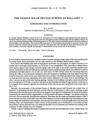
6. I06 M.G . DAVlES
F ipure I Part 01 the older part ot the school completed in I955seen lrom the North The site is on flat land. very little above sea level and a
lew hundred metres lrom the sea It is bery windswept
architecturally dissimilar however. The only description of the building provided by the architect is his Patent
S pecitication.
The Annexe is a two-storied building with a corridor aligned approximately east--west running the full
length of the building at ground floor level (seeFigure 2). It is in two sections. the larger housing the assembly
hall. kitchens. utility rooms. toilets and fiveconventional classrooms at ground floor level; upstairs the library.
artroom and science laboratory extend the full depth of the building (see Figure 3).The smaller section at the
east end has a dinerent alignment and houses the gymnasium and service rooms.
Both sections are provided with a solar wall. That of the larger section (Figure 4)is 70.2 rnlong by 8.7 rn high.
It is mainly double glazed with a separation of 62cm between the leaves (Figure 5). Above about 2cm
separation the thermal resistance of double glazing varies little with separation. A spacing of 62 crn allows easy
access for maintainance and accommodates the single glazed horizontally pivoted openable windows (see
Figure 6)in either of two securable positions. Three walkways are built between the leaves; they provide access
I'or maintenance and were seen to provide a barrier to the production of large convection currents. The panes of
both the inside and outside leaves are set in an iron frame of module 1.07 rnwide by 0.61 m high. This module is
used as the basis for the design of the building. Thus the ground floor occupies 4 full size modules (4 x 0.61 m)
Figure 2 Ground plan of the newer, solar heated part of the school. completed in 1961 The older part lies to the north-west of this
building and is connected with it by a covered walkway The two building complexes are run as a single unit
7. THE PASSIVE SOLAR HEATED SCHOOL IN WALLASEY. I 107
Figure 4.
building.
Figure 3 Section through the building The first floor overhangs the ground floor on the north side
The solar wall of the larger block from the south-west. The assembly hall at the western end extends the full height of the
The photograph shows the openable windows, a shuttercovered section of solar wall brickwork, some ventilator exteriors. a
small additional area of solar wall on the west elevation, and the marked slope of the roof
together with a lower inner leaf module at ground level. The upper floor occupies 8 modules of inner leaf. The
outer leaf has an extra module, making 14 in all.
Each window opening occupies 4 vertical modules in the outer leaf (see Figure 7). The topmost (module 4 in
Figure 7)is glazed. Modules 3 and 2 are void and face the openable window. Module 1 is also void but faces an
inverted vee section of double glazing. Modules 2. 3 and 4 provide single glazing. The horizontal frame
members of the outer leaf are located a little higher than the corresponding inner leaf members, presumably to
accommodate this ingenious window design. Each classroom has two openable windows. (The artroom has
three skylights in the roof near the north wall. These were originally single glazed and are now double glazed.)
8. 108 M.G . DAVIES
Figure 5. View of the interior of the solar wall looking east with a section of the shuttering on the left
The east-west dimensions of the rooms can be expressed in relation to an integral number of 1.07m
modules. From west to east: assembly hall 12modules,storage wall adjacent to the stage of the assembly hall 6.
utility room 3, further utility room 3, staff common room 3, staircase 2, classroom 7 (thisis the classroom upon
which estimates evaluated in Article I11 are based), study 4, classroom 7, staircase 2, classroom 6, classroom 6,
classroom 6. Continuing with the gymnasium block: changing room area 7, gymnasium store 3. gymnasium
double glazing 4, gymnasium storage wall 4, gymnasium double glazing 4, gymnasium storage wall 4,
gymnasium double glazing 4.
The storage wall sections adjacent to the gymnasium are ofconcrete, 35cm thick.The storage walls adjacent
to the assembly hall and in the staircase sections are of brick (see Figure 8). The storage sections are single
glazed and the outer surface of the brick or concrete lies in the plane the inner leaf elsewhere occupies. The
outer surfaces of the mass wall sections (Figure 9)are covered with a form of metal and paper cladding, painted
black. The areas are provided with vertical axis shutters which can be positioned so as to cover the mass wall
areas, or so as to allow radiation to fall on the wall. The shutter surface which is visible when the shutter is
folded against the wall is painted white to reflect sunshine and the shutters should be so positioned in summer.
The other sides of the shutters are clad in aluminium. When the shutters are positioned at right angles to the
wall, as they should be in winter, solar radiation falls directly onto the blackened surface of the mass wall, or is
reflected from the aluminium onto the surface. The architect’s intention was originally that the panels should
9. THE PASSIVE SOLAR HEATED SCHOOL IN WALLASEY. I I09
Figure 6. .Anopenable window in the open position. The lower and a similar upper grille make the window burglar proof when secured in
the open or closed position.The aluminium reflectorpanels areconcealed behind the pinboards on either sideof the window. A view to the
outside is only possible through the openable window and through the lowest panel of the solar wall. The central heating radiators were
installed as a precaution and are sometimes used. However,during the very severe winter of 1962-1963, the building provided satisfactory
thermal comfort using the heat of the lighting system. solar gain and body heat, without the use of these radiators
be operated thermostatically according to the outside temperature, but the 'difficulty in combining reliability
of operation with low cost caused the idea to be abandoned . . .' (Clayton, 1966)
The gymnasium block (Figures 10and 11) has a total east-west length of 33-8m. It has two heights. At its
westerly end it accommodates a metalwork room at first floor level, beneath which is the boys'changing room.
The height here is 8.7 m. The rest of the building, 23.5 m long by 5.5 m high, is the gymnasium proper (which of
course occupies the full height).
The main section ofthe solar wall faces about 16" west of south and the gymnasium section faces 14"east of
south.
The outer leaf is of clear glass. Nearly all parts of the inner leaf visible from inside the classroom areas are of
figured glass. This refracts light diffusely about the room. The object was to achieve a more uniform
distribution of radiation and therefore heat over the main room surfaces.
Less than half of the solar wall is in fact visible from within a downstairs classroom (Figures 12and 13);the
remainder of the wall is obscured by large pinboards. (This undoubtedly reduces glare, which casual visitors
have expected. Upstairs, the same area of pinboard constitutes a smaller fraction of the wall area though glare
is not seen as a problem except perhaps in the library.)Between each pinboard and the inner leaf--ofclear glass
10. I10 M.G . DAVIES
Figure 7. A close upof the shuttersadjacent to the staircase. The inner surfacesof the shuttersare lined with aluminium to reflectradiation
onto the blacked surface. The architect intended that the shutters should be actuatedby remote control but this was never implemented. It is
clear that the housing of an openable window occupies 4 frame modules
here -is a sheet of aluminium. Five such panels are present in the larger downstairs rooms and corresponding
upstairs rooms; their dimensions are 0.99 x 0.91 m2 downstairs and 0.69 x 0.91mz upstairs. The architect
intended that the bright side should be directed outward during summer to prevent part of the incident
radiation from entering the room, the matt black painted reverse being exposed in winter. With its black
surface outward the corresponding section of solar wall is rather less effective as a heat gatherer than is the
unobscured solar wall. These devicesshould be reversed twice a year. Thus the solar wall consists of sections of
single glazing, double glazing, double glazing with aluminium and wood layers attached, single glazed solid
wall and double glazed solid wall.
The horizontal and vertical surfaces of the rooms provide the thermal storage which is necessary to restrain
swings of temperature. The solid ground floor consists of lOcm screed upon 15cm of dense concrete; the
intermediate floor consists of 23cm of concrete and the roof of 18cm of concrete. Most of the floor area is
covered with thermoplastic tiles. The floor of the gymnasium is a suspended wooden floor and that of the
assembly hall consists of wooden boards laid on concrete. The vertical partition wallsand the north wall at first
floor level are 22cm of solid brick.
The roof and vertical outside walls are clad on the outside by a 13cm thickness of expanded polystyrene
suitably protected by bitumen vapour barriers and roofing felt. This provides excellent insulation with a
thermal transmittance, U. of around 0.24 W/m2K.
The east-west corridor at ground floor level is largely shaded from solar radiation and its north wall
accordingly is not provided with much thermal storage. The north wall is a timber framed, timber clad wall,
also containing 13cm of expanded polystyrene; it is described in the plans as ‘ranch walling’. The north wall is
broken by a toilet area,which is,surprisingly, provided with solar walling. Part of the west wall of the assembly
hall is also of solar construction, perhaps to achieve a 2 per cent daylight factor. (Skylights might have been
more effective.)
11. THE PASSIVE SOLAR HEATED SCHOOL IN WALLASEY. 1
I l l
Figure 8. A solid wall replaces the inner leaf of the solar wall to the east of the assembly hall and occupies 6 frame modules. The section is
provided with shutters. The lower bank are shown positioned to reflect radiation from their white painted surfaces.The upper bank are
positioned to allow radiation to fall onto the black painted surface of the brick. A walkway is positioned between the banks. and a further
walkway is above the upper bank. The internal frame members of the solar wall are visible. Handrails at hand height and above the upper
walkway are to be seen
Ventilation control is provided by the openable windows (Figure 6).Except in the extreme position they lie
within the width of the solar wall. The seating ensures that there is little air infiltration when the window is
secured closed. Each window can be secured closed by the simple action of a handle (see Figure 14).By an
unfortunate omission, the windows can only be secured in the open position by the use of a key. This is not
done, windows are invariably closed by night and the cross-ventilation the architect intended in hot weather
(Morgan. 1966,p. 5, line 74)is not achieved. The provision of bars below and above the windows could ensure
that the windows were burglar proof both open and closed.
Ventilation through solid walls is provided by the adjustable ventilators (Figures 15-17). There have been
minor troubles associated with this design. Ventilators of this kind are provided in the gymnasium, 8 on the
north wall and 6 on the east wall (see Figure 18).There are no openable windows there.
The doorway into the Annexe from the Main School provides a point of uncontrolled ventilation. All
outside points of access have double doors (Figure !9) which move together and have a rubber seal on the
abutting edges. With their sprung return they are somewhat more cumbersome than ordinary doors would be.
Openable windows at high level are also provided between corridor and classroom (Figure 20). Although
12. 112 M.G. DAVIES
Figure 9 One of the two sections of mass wall in the gymnasium. The wall is of concrete and occupies 4 frame modules. Its outer surface
replaces the inner leaf of the solar wall
Figure 10. The boys’ gymnasium is situated at the extreme east end. The west end of this section houses a metalwork room at first floor
level. behind which is a woodwork room which is provided with a clerestory section of solar wall
these could be effective by night, the staff tend to keep them shut during occupation even in hot weather,
because of the noise from the corridor. There is also glazing at low level between corridor and classroom.This
ensures sufficient illumination on the corridor floor;the lighting level in the corridor is otherwise rather poor.
Supplementary heat for the building is normally supplied by the lighting system. In summer lights are
operated in the normal way. In winter the switches are normally left in the ‘on’position. A time clock switches
all lights on at some predetermined time in the morningand they remain on throughout the day unless they are
13. THE PASSIVE SOLAR HEATED SCHOOL IN WALLASEY. I 113
Figure I I View from the north-west. The photograph shows (from left to right) the gymnasium louvres, the woodwork room with some
solar walling beneath, louvies for the main part of the solar building, and more solar walling serving the toilets area
Figure I2 View of the classroom towards the southeast. The curtains were installed so that a slide projector could be used. The
photograph includes six of the seven frame modules that form the east-west dimension of the room.The Sevenlights (fiveare visibleon the
photo)serveasa main source of heat. A stripof hardboard adheres to the west wall. A bench/cupboard (notclearly visible)is built up to the
wall. This reduces thermal storage a little
turned offindividually.All lights are turned off again in the evening. The times are adjusted in accordancewith
the weather.They are turned off altogether during the Christmasholidaysand may be left on 24 hours a day for
a few days before term begins. The hot water radiators are sometimes used.
14. I14 M.G . DAVIES
Figure I 3 View 01 the artroom The pinboards occupy a fractionally much smaller area upstairs than down
Figure 14 Detail 0 1 the clasp action of the windows. Use of this clasp secures the window in the closed position and it is easy to elTect.
Means are provided. using a special key. to secure the windows in the open position. but this is tedious to do and the windows are secured
closed by night The summer cross-ventilation that the architect intended should be achieved is thus not achieved, with some resulting
overheating
15. THE PASSIVE SOLAR HEATED SCHOOL IN WALLASEY. I 1 I5
Figure 15 View of the artroom toward the north-east. Three ventilators covered with teaching material are visible on the north wall
Figure 16. South-west corner of the assembly hall, showing the ventilators and doorway interior. The floor is of timber
16. 1 I6 M.G. DAVIES
Figure 17. Close. up of a ventilator in the artroom
By normal heating standards, the lighting system is inadequate as a source of heat, and it has become
relatively expensive since it is on the normal tariff. However, it will be noted that the heatingeffect of switching
on lights is immediate and perceived everywherein the room. The presence ofa direct source of radiation. short
or longwave. is equivalent to an increase in room temperature.
THE THERMAL BEHAVIOUR OF THE CONSTRUCTION
The period between the completion of the building and the death of the architect may not have been suffcient
tor suffcient reliable empirical evidence on the behaviour of the building to have been accumulated to provide
tirm information about its actual thermal behaviour.
The Borough Architect commented in February 1966:
The system has a great many advantages relating to comfort, health and planning. Heat is distributed
throughout the building by radiation in the same way as light instead of by pipes, radiators, etc.
By the omission of pipes and radiators, etc., teaching rooms have more floor and wall space
available for apparatus. Unlike other heating systems the air is not used as a vehicle to distribute the
heat, thus the air need not be at a high temperature and ventilation is quite independent of the heating
of the building. It has been clearly established in heating research that where the temperature of walls,
ceilings and floors is higher than that of the air, this gives the most ideal conditions of comfort. Also
17. THE PASSIVE SOLAR HEATED SCHOOL IN WALLASEY. I 1 I7
Figure 18. Gymnasium showing the ventilators in the north and east walls
temperatures of the fabric being higher than the air the body heat of the occupants is not lost into the
fabric as in normal buildings.
This temperature relationship also greatly reduces the rate at which interior decorations become
dirty by contact with dust in the air. and furthermore in hot summer conditions the temperature of
the interior can be maintained at a level several degrees lower than that of a conventional building,
the building's design properties resisting any rapid change of temperature. and this, combined with
ventilation during the cool night hours maintains an average much below that of the heat of the day.
A proportion of heat is also provided by body heat of the occupants. In the winter months when
the school is unoccupied during holidays and at weekends, because of the high thermal capacity of
the building the temperature falls only slowly. even in severe weather. and by operating the ordinary
tungsten lamps of the lighting installation on a time switch, the temperature can be raised to a
satisfactory level before the school re-opens.
The scientific calculations were Mr. Morgan's and were never disclosed by him. (Clayton. 1966).
Since Mr. Clayton had been concerned with the school from its inception, these remarks probably provide
the most reliable summary of the understanding of the building that was available at the time, though he had
access to the report by Hitchin et al. (1966).
A more detailed description of the thermal response will be given in the third and fourth articles of this series.
Attention may be drawn, however, at this stage to some useful early publications: Hitchin et al. (1966).Love
(1968).Manning (1969).and Davies and Davies (1971).It is worth quoting at length from Banham's discussion
of the building (1969):
Of the example about to be discussed, it has been said that any panel of accredited environmental
experts to whom it might have been submitted would have found themselves bound to dismiss it as
impracticable.The revenges of time are sweet,however, and established experts are reckoned to have
spent more time and energy in trying to find out how it works than was ever lavished on it by its
original designer.
18. 118 M.G. DAVIES
Figure 19 One of the 7 doorways into the building.Thedoorsaredoubleactingand are provided with a spring return.They are too heavy
to be moved by small children. The abutments are lined with deformable rubber so as to reduce air infiltration
The building in question is the second block of St George’s County Secondary School in Wallasey
(Cheshire, England). Completed in 1961. it belongs to that same generation of experimental
environmental essaysthat were discussed in the previous chapter, but unlike them it has not enjoyed a
world-wide press, doubtless because of the small fame of its designer, Emslie Morgan, principal
assistant to the Borough Architect of Wallasey. Though he now has a secure reputation because the
building has become something of a legend or cause celebre among British environmentalists,he died
before that fame was established,leaving no documents that can now be traced to record his thoughts
and methods. The double lack, of both autograph documents and of any intelligent interest on the
part of architectual publications when Morgan was alive, means that the present study can derive
only from inspection of the structure as it stands and as it functions . . ..
‘Structure’ is the word to emphasise, because what Emslie Morgan has offered in St George’s
School is an imaginative reappraisal of one of the oldest environmental controls known to man,
massive structure functioning to conserve heat, plus an attempt at improved exploitation of the
oldest and ultimate source of all environmental power, the sun. The structure is almost ludicrously
heavy by the standards now current in British school building-nine inch brick walls, seven-inch
concrete roof all wrapped in five inches of external foamed polystyrene insulation, plus further layers
of cladding for various purposes. In plan, the block is long and narrow . . . . (On the south side, the
roof) pitches up to over forty feet thus providing a vast area of glass to the sun.
19. THE PASSIVE SOLAR HEATED SCHOOL IN WALLASEY I I I9
Figure 20. View of a classroom towards the north-west.The classroom-tocorridor windows could be opened to achieve cross-ventilation
but they are normally kept closed since the corridor can be noisy. The photograph shows a sloping section to the roof, incorporated
perhaps to assist daylight levels away from the solar wall. It also shows the blackboard housing and a cupboard beneath. These reduce a
little the thermal storage provided by the double thickness brick west wall
In the designer's mind, this 'solar wall' was undoubtedly the key to the functioning of the whole
building, and has also been the aspect that has caught the fancy of the public. It consists of two skins
of glass, separated by a space of 24 inches, the outer skin being clear, the inner one consisting almost
entirely of obscured glass, to shed a diffused light into the teaching areas. Some of the inner skin is of
clear glass . . . [Banham describes the aluminium panels].
Similarly, there are areas of the inner skin, in the assembly hall and gymnasium, that have been
replaced by black-painted masonry, thermal performance being controlled by white wooden shutters
that can be hung over them to reduce the absorption of solar heat.
It will be noticed that Morgan's use of glass avoids the traditional function of glazing-to be
transparent to sight. There are. in fact, panes of clear glass in the hinged ventilation-windows that
occur at intervals on both storeys of the facade, but they provide only scanty outward views. For this,
and a tendency to overall glare from the glazed side of the rooms, the visual environment of the
school has been subjected to some criticism. But about its thermal environment there seems to be no
surviving doubt. now that its emergency hot-water heating system has been removed, unused, after
the school had survived almost the worst winter in living memory (1962-3).
The heat so efficiently stored and managed by the massive structure has three main sources: the
solar wall, the electric lighting, and the inhabitants. Of these, the solar wall may prove to be the least
productive for most of the year, and the weak point in the school's armour of insulation in the cold of
winter. The next most important source of heat is commonly taken to be the lights, which are
switched on early to preheat the school before the pupils arrive, and some conservatively minded
engineers have therefore described it as an electrically heated building. But the greatest source of heat
20. 120 M. G. DAVIES
is,in fact, the inhabitants themselveswho, in a normally occupied class-room, provide about half the
winter heat input per hour. Even if it is the total management of the heat balance which is important
here,the attempt to use the waste heat from the lights at a date well before the commercial availability
of systems like Barber-Coleman Daybrite (whichuse heat-of-light to warm input air at the point of
delivery) is worth a note in any history of environment.
Nevertheless,it is the total view of the thermal environment of the complete man/structure/lighting/
ventilating system that is impressive,as well as the simplicity of the methods for its control: a time-
switch for the lighting’s contribution to the diurnal heat balance, reversible panels for seasonal
variations, and a card of instructions for each classroom on how the ventilation should be adjusted
(by opening or closing the windows) to deal with short-term increases or drops of temperature.
One could object that this is too irregular and fortunate a case for any useful lessons to be learned
from it;irregular in that it seemsto work well but at variance with the designer’sintentions for how it
should work (asin the case of the solar wall),and fortunate in that it seemsto enjoy both a site that is
admirably suited to the proposition, and a local climate marginally more helpful to its working than
many others might be, even in the Same part of England. There can be no doubt that it is a special
solution to a special problem, and less than perfect at that-difficulties with overheating on a few
days of strong sun and no wind in high summer suggest that it needsa mild breezy climate even more
than the direct incidence of sunlight for which Morgan designed it. But where is the building that
does not have a few days of environmental difficulties in the year? By the going standards of
environmental judgement, St George’s School has proved itself as much of a success as any other
building discussed in this book, and better than most.
Its successful performance guarantees its right to be discussed here, no more; the reason for
discussing it is less than it works than because it works through the application of the ultimate form
of environmental, and all other, power-knowledge. Even if Morgan were to prove mistaken in
details, the overall proposition that he made presupposes knowledge of the total system socomplete
that one can judge what to omit-the heating system was never more than a hedge against
unforseeable failure to function; it was never meant to be used and never was used. The professional
courage to attempt such a radical reassessment of methods of environmental management can only
come when quantifiable technological knowledge, derived from experience and controlled exper-
iment, has acquired the same sort of completeness and authority as the accumulated rules of thumb
by which vernacular cultures manage their environments.
REFERENCES
Banham, Reyner. (1969).The Architecture 01the Well-tempered Environment, The Architectural Press, London.
Billington, N. S. (1947). ‘Solar heat gain through windows’, J . Royal Institute of British Architects, 54, 177-180.
Clayton, W. P. (1966).‘Notes on the new St. George’s Secondary School, Leasowe. (Solar energy)’, County Borough of Wallasey-an
Davies A. D. M. and Davies, M. G. (1971).‘User reaction to the thermal environment-the attitudes of teachers and children to St.
Davies, M. G. (1976).‘The contribution of solar gain to space heating’,Solar Energy, 18, 361-367.
Hammond, G. W. and Trubshaw, G. E. (1968).‘TheMorgan principlesfor solar heated buildings’,unpublishedarticle presentedat the
Hitchin, E. R., Thompson, K. and Wilson, C. B. (1966). ‘The thermal design and performance of St. George’s County Secondary
Love, J. (1968).‘Economic comparison of the solar and conventionally ’heated sections of St. George’s !kondary Modern School,
Manning, Peter. (1969).‘St. George’sSchool,Wallasey: an evaluation of a solar heated building’,Architects Journul Injormation Library,
Morgan, E. A. (1966).‘Improvements in solar heated buildings’, U.K.Patent Specijication 1022411, application date 6 April 1961,
internal note, dated 8 February 1966.
George’s School, Wallasey’, Building Science, 6, 69-75.
Thermal Insulation Conference, Cardiff, December 1968.
School, Wallasey’, J. Inst. Hear. Vent. Engrs., 33, 325-331.
Wallasey’. T.R.G.Report 1636, H. M. Stationery Office.
25 June, 1715-1721.
complete specification published 16 March 1966, The Patent Office, London.