7. NOTE: The term transmission refers to rear-wheel-drive vehicles and the term transaxle usually refers to front-wheel-drive vehicles that have a differential built into the unit. A separate differential is used with a transmission.
8.
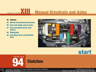
9. Figure 94–1 Typical automotive clutch assembly showing all related parts. (Courtesy of LUK) Continued
10.
11. Figure 94–2 (a) When the clutch is in the released position (clutch pedal depressed), the clutch fork is applying a force to the throwout (release) bearing, which pushes on the diaphragm spring, releasing the pressure on the friction disc. Continued
12. Figure 94–2 (b) When the clutch is in the engaged position (clutch pedal up), the diaphragm spring exerts force on the clutch disc, holding it between the flywheel and the pressure plate. Continued
13.
14.
15.
16. Figure 94–5 A hydraulic clutch linkage uses a master cylinder and a slave cylinder. Continued
17.
18.
19. Figure 94–7 A racing or high-performance clutch disc lacks the features of a stock clutch disc that help provide smooth engagement. Continued
20.
21. Figure 94–8 A typical stock clutch friction disc that uses coil spring torsional dampers. Figure 94–9 A marcel is a wavy spring that is placed between the two friction surfaces to cushion the clutch engagement. Continued
22. HINT: The larger center hub section of the disc must be installed with the thicker portion facing the pressure plate Figure 94–10 Cutaway of the center section of a clutch plate showing the various layers of steel plates used in the construction.
23.
24.
25.
26. Figure 94–12 Typical diaphragm-style pressure plate that uses a Belleville spring. Continued
27.
28.
29.
30.
31.
32.
33.
34.
35.
36.
37. Figure 94–16 (a) Before replacing the clutch, the bell housing should be cleaned and the clutch fork pivot lightly lubricated. Figure 94–16 (b) The input shaft seal should also be replaced to prevent the possibility of getting transmission lubricant on the friction surfaces of the clutch. Repair the Oil Leaks Before Replacing the Clutch - Part 2
38.
39. Figure 94–17 A transaxle assembly has been removed to replace the clutch. Note the short input shaft. This vehicle did not use a pilot bearing (bushing). Continued
40.
41.
42.
43.
44. Figure 94–18 The clutch pedal linkage moves the clutch fork, which then applies a force against the release bearing, which then releases the clamping force the pressure plate is exerting on the clutch disc. Continued
45.
46. Figure 94–19 The release bearing rubs against the tips of the diaphragm spring. Continued
47.
48.
49.
50.
51.
52.
53.
54. Figure 94–20 Heavy chatter marks on the pressure plate indicate that oil or grease has gotten onto the clutch facing. (Courtsey of LUK) Figure 94–21 Hot spots on the pressure plate indicate that this clutch has been slipping or that oil/grease has gotten onto the clutch facing. (Courtesy of LUK) Continued
55. Figure 94–22 Friction material (facing) worn down to the rivets. Normal wear can cause this or improper clamping force from a defective pressure plate. (Courtesy of LUK) Figure 94–23 Friction material (facing) only makes contact with the flywheel on the inner and outer edge. The likely cause is that the flywheel was not resurfaced or replaced during a previous repair. (Courtesy of LUK) Continued
56. Figure 94–24 Deep scoring in the friction material (facing) on the flywheel side indicates that the flywheel was not resurfaced or replaced during a previous repair. (Courtesy of LUK) Figure 94–25 A broken cushion segment caused by movement between the engine and transmission. The most likely cause is a missing or defective pilot bearing. (Courtesy of LUK) Continued
57. Figure 94–26 A destroyed torsional damper is usually caused by driving at too low an engine speed, which would cause too much strain on the torsional damper. (Courtesy of LUK) Figure 94–27 A worn down or broken diaphragm is often caused by a faulty release bearing or a linkage problem that keeps the clutch from fully releasing. (Courtesy of LUK) Continued
58. Figure 94–28 Rusting hub splines indicate that the transmission shaft was not lubricated, which can cause the clutch to not disengage correctly. (Courtesy of LUK) Continued
59.
60.
61.
62.
63.
64.
65.
66. Figure 94–30 To check that the clutch is properly installed before replacing all of the components, try to turn the output shaft with the transmission in gear and the clutch pedal depressed by an assistant. Continued
67.
68.
69.
70.
71.
72. Figure 94–31 The clutch slave cylinder is often corroded because of moisture absorbed by the brake fluid used in the hydraulic clutch. This slave cylinder was disassembled to see if it could be overhauled rather than replaced. Continued
73. Figure 94–32 (a) The replacement hydraulic clutch for a Saturn includes the master cylinder (shown) with the line and the slave cylinder as an assembly. The assembly is even filled with brake fluid! Do not open the master cylinder cap on this unit because Saturn did not provide any method of bleeding air out of the ignition. Continued
74. Figure 94–32 (b) The slave cylinder attaches to the bell housing of the transaxle. Continued
![[object Object],[object Object],[object Object],OBJECTIVES: After studying Chapter 94, the reader should be able to: Continued](data:image/gif;base64,R0lGODlhAQABAIAAAAAAAP///yH5BAEAAAAALAAAAAABAAEAAAIBRAA7)