Smartmax IO Board MA – 4020 - Maxon Solutions

You can transform the Smartmax M2M HSPA smart modem into a cost effective mini RTU having an I/O interface controller. The modem can be used in conjunction with other compatible Maxon Smartmax modems for data telemetry purposes. The I/O interface controller provides wide ranging flexibility for integration with various system devices and automation processes required for controlling and monitoring varied field application systems and devices. Local as well as remote programming of the I/O interface controller can be carried out via a built-in web interface. The feature rich web interface application facilitates the programming of DNP3 settings and also supports I/O status updates via SMS utilities. The modem connects directly to the IO board through a ribbon connector, and the I/O controller can be set up or wired to collect data automatically. Connect directly to a host of Remote Terminal Units (RTUs), Intelligent Electronic Devices (IEDs), sensors, meters, loggers, and process equipment. The Smartmax M2M HSPA smart modem when used in conjunction with the I/O interface controller board offers ultimate cost effective data logging and device monitoring solutions.

Empfohlen
Empfohlen
Weitere ähnliche Inhalte
Was ist angesagt?
Was ist angesagt? (18)
Andere mochten auch
Andere mochten auch (15)
Ähnlich wie Smartmax IO Board MA – 4020 - Maxon Solutions
Ähnlich wie Smartmax IO Board MA – 4020 - Maxon Solutions (20)
Mehr von Maxon Data Communications
Mehr von Maxon Data Communications (15)
Kürzlich hochgeladen
Kürzlich hochgeladen (20)
Smartmax IO Board MA – 4020 - Maxon Solutions
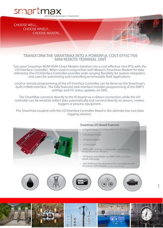
- 1. M2M HSPA Smart Modem Solution - I/O Board: MA-4020 CHOOSE WELL... CHOOSE WISELY... CHOOSE MAXON... TRANSFORM THE SMARTMAX INTO A POWERFUL COST-EFFECTIVE MINI REMOTE TERMINAL UNIT Turn your Smartmax M2M HSPA Smart Modem Solution into a cost-effective mini RTU with the I/O Interface Controller. When used in conjunction with Maxon’s Smartmax Modem for data telemetry, the I/O Interface Controller provides wide-ranging flexibility for system integrators and users for automating and controlling innumerable field applications. Local or remote programming of the I/O Interface Controller can be done via the Smartmax’s built-in Web Interface. The fully featured web interface includes programming of the DNP3 settings and I/O status updates via SMS. The SmartMax connects directly to the IO board via a ribbon connection, while the I/O controller can be wired to collect data automatically and connect directly to sensors, meters, loggers or process equipment. The Smartmax coupled with the I/O Interface Controller Board is the ultimate low cost data logging solution. Smartmax I/O Board Features • 6 Digital Inputs (1 configurable as pulse input) • 2 Analogue Inputs • 4 Digital Outputs • DNP3/SMS Settings configurable via web page inside Smartmax Modem. • I/O Board controllable via DNP3, SMS, or using inbuilt web page. • SDK (Software Development Kit) is available for the Smartmax HSPA Modem (Product Code: MA-2010) 170908 *N ot to s ca le • 1 Pulse Input
- 2. M2M HSPA Smart Modem Solution - I/O Board: MA-4020 Frequency Bands • WCDMA/HSPA 850MHz, 900MHz, 1900MHz, 2100MHz • GSM/GPRS/EDGE 850MHz, 900MHz, 1800MHz and 1900MHz General Features • Packet Data 6 Digital Inputs Characteristics • 2 Way SMS · VIH (Input voltage high range): 2 ~ 24V • Remote SMS diagnostics & reset · VIL (Input voltage low range): -2 ~ 0.8V • Embedded TCP/IP, UDP/IP STACK · Ri (Input impedance): more than 5 kΩ • In-built periodic reset · Rd (Internal pull-up): 47 kΩ for short to ground detection • External DC Powered Metering Connection Specifications · Input chatters are filtered by S/W setting • Support VPN Server and Client Mode Water • Dynamic DNS • Supports DNP3 (Outstation) using extension I/O board • • In-Built Web Interface • Programmable scheduler to control WAN connection • Road Signs Rugged Metal Casing for industrial use Telnet support • Save and restore modem configuration from a file • FOTA - Firmware upgrade over the air • External antenna connectivity to maximise HSPA coverage • External LED to show Network and Connection status 1 Pulse at Input 0 · Frequency range 0 ~ 1000 Hz · Accuracy (25°C) 0.05 % of span · Temperature stability 0.005 % / °C · Input impedance 47kΩ 4 Digital Outputs · MOSFET switch to ground · Ro (Output resistance): less than 300 m Ω · VOpen (maximum allowed output voltage on open): 24 VDC · Security Connections • 6 x Digital Inputs (INPUT 0 ~ INPUT 5 in terminal block) • 4 x Digital Outputs (OUTPUT 0 ~ OUTPUT 3 in terminal block) • 2 x Analog Inputs (ANALOG 0 and ANALOG 1) • 1 x Pulse Input (INPUT 0) Transport • 1 x Case Open • 1 x Battery (Monitor Battery Level) • 1 x 20 Pin Terminal Block (SmartMax Interface) IOut (maximum allowed switching current to ground): 1A · Switching time < 10 msec · Chatter free 2 Analog Inputs · 12bit resolution · Accuracy: Typical ±0.25% ; Worst Case ±1% · Maximum sampling rate: 10 sample/sec · Input signal type: one of 0~20mA, 0~5V, or 0~10V · (The input type is selected by the jumper “PULSE” on the connected Smartmax and INPUT# on the I/O board) · Power Environmental Specifications Input impedance for the signal type 0 ~ 20mA < 100Ω · Input impedance for the signal type 0 ~ 10VDC > 10K Ω • Normal Operation Temperature -20 to 60° C • Extreme Operation Temperature -25 to 75° C Compliance www.maxon.com.au • RoHS Compliant Dimensions • 210mm X 1100mm X 650mm (with connectors) A mini usb cable is required for first time purchasers of the Smartmax, as most of the programming can only be done via the web interface. This is available in the Smartmax Complete Package (MA-2010C), the Smartmax SDK (MA-7000), and separately. Speak to your Maxon Account Manager for more information. T | +612 8707 3000 ● F | +612 8707 3001 ● E | sales@maxon.com.au ● 36A Gibson Avenue, Padstow NSW Australia 2211 ● www.maxon.com.au