
Empfohlen
Weitere ähnliche Inhalte
Was ist angesagt?
Was ist angesagt? (19)
Ähnlich wie Laser Shock Processing
Ähnlich wie Laser Shock Processing (20)
Mehr von LSP Technologies
Mehr von LSP Technologies (10)
Kürzlich hochgeladen
Kürzlich hochgeladen (20)
Laser Shock Processing
- 1. LSP Technologies, Inc. Laser Shock Processing Technical Bulletin No. 1 Introduction What Does It Do? Laser Shock Processing (LSP) produces a number of beneficial effects in metals and alloys. Foremost among these is increasing the resistance of materials to surface-related failures, such as fatigue, fretting fatigue and stress corrosion cracking. It does this by driving compressive residual stresses deep into metals and alloys. Much deeper than shot peening. For these applications the process is referred to as laser shock peening. There are a number of other reasons to use LSP besides increasing fatigue strength and fatigue life; it can be used to strengthen thin sections, work-harden surfaces, shape or straighten parts, break up hard materials, possibly to consolidate or compact powdered metals, and still others remaining to be discovered. Applying LSP LSP can often be applied to the finished surface of a part, or just prior to the final finishing step. In machine components, tooling and other parts, application to external surfaces and internal surfaces with line-of-sight access is straightforward. Application to internal surfaces without line-of-sight access is quite possible, but the method used is application specific and requires some development for each application. LSP works by exerting a mechanical force on the part surface; the surface is not affected thermally. However, process options can be selected which have a limited thermal effect and offer potential cost benefits. The effects of the mechanical force on the surface itself are minimal. In softer alloys, a very shallow surface depression occurs, which decreases in depth in harder materials. For example, in aluminum alloys, the depression is about 250 minches (6 mm) deep, but on machined surfaces of harder alloys, it is difficult to see where the surface was laser shocked. The depth of the depression does increase with increasing intensity of shock peening. With LSP, treating just the fatigue critical area(s) on a part without masking the area around it is easily accomplished. This enables localized treatment around holes, and in and along notches, keyways, fillets, splines, welds, and other highly stressed regions. The intensity of LSP can be easily controlled and monitored, allowing the process to be tailored to the specific service and manufacturing requirements demanded by the part. The flexible nature of the process accommodates a wide range of part geometries and
- 2. 2 sizes. It can also be used in combination with other treatments, e.g., shot peening or coatings, to achieve the most beneficial property and cost advantages for each part. LSP can also be used in manufacturing processes requiring a high, controllable, mechanical impact over a defined area, where mechanical punches are limited in how they can be adapted to the task. The impact area could have a variety of shapes. The first production application of laser shock peening began in 1997 on a military gas turbine engine blade. More production applications will begin in 1998. Benefits The use of LSP to obtain increased strength and resistance to failure offers several advantages. After applying LSP to failure-prone areas on troublesome parts, the service life of the parts and the maintenance intervals of machinery can be increased and downtime decreased, without changing the design. Alternatively, a part or machine can be redesigned to make them lighter, easier to manufacture, or less expensive, using LSP to upgrade the properties to meet the original design performance requirements. It is a new manufacturing tool that could offer more control, flexibility or unique effects for upgrading current products or developing new ones than other methods. LSP Technologies, Inc. LSP Technologies, Inc. provides commercial laser shock processing services and equipment. We are the only company providing LaserPeenTM laser peening services to industry, and building LaserPeenTM equipment specifically for laser shock processing applications. In 2000 we will be introducing our new RapidPeenTM process and associated RapidPeenTM equipment for increased throughput and lower cost. In 2001 we will introduce a factory-floor ready laser shock peening system. LSP Technologies’ key management and staff have many years of experience in the development and use of laser-generated shock waves for a wide variety of applications. Our staff’s experience dates back to the early 1970’s, when we began developing the technology at Battelle Memorial Institute in Columbus, Ohio. The company is located in Dublin, Ohio, a suburb of Columbus, in new facilities for production processing of parts and development of new applications. The facility has two laser shock peening systems that provide flexibility for processing a wide variety of parts. The Laser Shock Process The Laser Shock Process is a mechanical process for treating materials, not a thermal process. The laser is a high-energy, pulsed Neodymium-glass laser, producing a very short pulse, 15 to 30 nanoseconds long, having a wavelength of 1.06 mm, with an energy
- 3. 3 per pulse of 50 joules or more. The laser beam is directed from the laser through an optical chain of mirrors and lenses onto the surface of the part being treated. Description of the Process A schematic of how the process works is shown in Figure 1. The area to be treated on a part is locally covered with two types of overlays: an opaque overlay, opaque to the laser beam directly on the surface of the part, and over this a transparent overlay, transparent to the laser beam (Figure 1a). The opaque overlay can be any material opaque to the laser beam; a black coating is commonly used. The transparent overlay can be any material transparent to the laser beam; water is commonly used. When the laser beam is directed onto the surface to be treated, it passes through the transparent overlay and strikes the opaque overlay. As shown in Figure 1b, when the laser beam strikes the surface of the opaque overlay, it immediately vaporizes a thin surface layer of the overlay. This vapor then absorbs the incoming laser energy, rapidly heating and expanding against the surfaces of the workpiece and the transparent overlay. a. Surface area to be laser shocked, showing the laser beam and overlays. b. Effect of laser beam at the overlay-workpiece interface. Figure 1. Schematics of how the laser shock process works.
- 4. 4 The transparent overlay acts to trap the thermally expanding vapor against the surface of the workpiece, and consequently causes the pressure to rise much higher than it would if the transparent overlay were absent. The sudden, high pressure against the surface of the workpiece causes a shock wave to propagate into the material. If the peak stress of this shock wave is above the dynamic yield strength of the material, the material yields and plastically deforms. As the stress wave propagates deeper into the material, the peak stress of the wave decreases, but deformation of the material continues until the peak stress falls below its dynamic yield strength. This plastic deformation caused by the shock wave gives rise to the compressive residual stresses at the surface of the workpiece (Figure 1b). This is one of the most useful effects caused by LSP. The shape of the laser treated spots is generally round, but other shapes can be used, if necessary, to provide the most efficient and effective processing conditions. The size of the area treated in one pulse depends on a number of material, laser and processing factors. The spot size can range from about 1 inch (25 mm) to about 0.1 inch (2.5mm) in diameter. A typical spot size for the development laser is about 0.25 inches (6 mm) to 0.35 inches (9 mm) or larger. Processing Parts In practice, the laser is located next to a work station in which the parts are held and manipulated during processing. A part is placed in the work station by loading it into a fixture, then the part and fixture are moved into the proper position for processing. After positioning the part, the laser beam is directed into the work station, treating the desired spot on the part. The part is then either moved to the next position for the following shot, or is removed from the work station and replaced with the next part. For a high-rate production run, each of the work station steps: part pick-up, positioning, processing and removal, would be performed automatically. With the current developmental laser-work station arrangement some of these steps are being performed manually. Parts are set up for laser shock processing in either of two ways. For thicker sections, nominally 0.5 inches (12 mm) thick or more, a single beam enters the work station and is directed onto the area being treated. To minimize distortion of the part in thinner sections the laser beam is usually split into two beams of equal intensity, and these beams strike the part on opposite surfaces simultaneously. Thin sections can be treated from one side only, if necessary, by using a back up support. The size of the area to be treated depends on the part design and service conditions. Sometimes, a part requires that only a small area be treated and a single treated spot will suffice, e.g., around small oil, pin or bolt holes, or at the root of a notch in the side of a thin section. In other instances, the areas requiring treatment will be larger, e.g., an area on a turbine blade, crankshaft fillet, or gear. In these cases, successive spots are overlapped until the desired region is completely covered. Laser Shock Peening
- 5. 5 When laser shock processing is used to increase fatigue life, straighten or shape parts, increase stress corrosion cracking resistance, or for other applications where surface compressive residual stresses are used to provide the desired result, it is referred to as laser shock peening instead of laser shock processing (although both will be referred to as LSP). In these applications it acts in much the same way as shot peening, except that LSP drives the compressive stresses and work hardening deeper into the material without significantly degrading the surface. All past experience indicates that LSP can be used for any material and application for which shot peening has been used. It is not expected that laser peening will replace shot peening for large area coverage. Indeed, in some cases it may be best to combine the two processes, laser shock peening the fatigue critical areas and shot peening the rest of the part surface. Properties of Laser Shock Peened Materials A number of metals and alloys have been treated by LSP, including steels, aluminum alloys, titanium alloys, nickel-base superalloys, cast irons and a powder metallurgy iron alloy. In most cases, these investigations did not include both residual stresses and fatigue results in the same study, or directly compare LSP and shot peening. However, the information presented here clearly illustrates the residual stress distribution, fatigue, strength and hardness changes representative of LSP in a variety of alloys. It should be emphasized that none of the results shown here represent the optimum or maximum benefit condition for the particular material or application. The nature of the residual stresses will be shown first, followed by fatigue, then strength and hardness properties. Residual Stresses All residual stresses were measured using x-ray diffraction. The existence of residual stresses at the surface of a crystalline material creates elastic strains in the crystal lattice that alters the spacing between the lattice planes, i.e., tension increases the spacing and compression decreases the spacing. The x-ray diffraction technique measures the spacing of the crystallographic lattice planes at the surface of the part. The difference in the measured lattice spacing at the surface of the part from that of an unstressed crystal lattice of the same material is due to the presence of the elastic strains at the surface of the part. The measured elastic strain is then related to the residual stress through the elastic moduli of the material, allowing the residual stress to be calculated from the x-ray measurements of the lattice strain. The distribution of the residual stress below the material surface was determined by successively removing a thin layer from the surface by electropolishing, then making x- ray measurements on the new surface. Electropolishing does not introduce stresses into the surface as would machining or grinding. This incremental process was continued
- 6. 6 down to the maximum depth of interest, usually 0.020 to 0.050 inches (0.5 to 1.2 mm) deep. An analytical technique was then used to calculate the stress distribution below the surface as it existed before disturbing it by removing the layers. This analytical technique accounts for both the stress relaxation occurring as material is removed, and for the depth of penetration of the x-rays into the stress gradient. Surface Distribution of Residual Stresses It is important to have relatively uniform residual stresses across the treated area on a part, and LSP provides this. The surface stress distribution along the radius of a laser shock peened spot is shown in Figure 2 for an aluminum alloy. This is typical for all other alloys where surface distributions were determined. The stress distribution is essentially uniform except for a slight dip in the center of the spot. There has been no evidence that this dip has affected fatigue behavior. In the next section, it will be seen that the dip extends only a few thousandths of an inch below the surface. In Figure 2, the residual stresses in both the tangential and radial directions are shown. These stresses are nominally equal in the interior of the laser treated spot, but at the spot’s outside edge, they tend to differ. Immediately outside the treated spot a surface tensile residual stress forms tangentially to compensate for the compressive stresses inside the spot, whereas in the radial direction this effect is often absent. To avoid having this peripheral tensile residual stress affect the post-processed properties, the treated area must be large enough to move this stress outside the fatigue-critical area. 40 Radial Stress 20 Tangential Stress Residual Stress, ksi 0 Laser Shocked Region -20 7075-T6 -40 -60 -80 -100 0 1 2 3 4 5 6 Distance from Center of Laser Spot, mm Figure 2. Uniform surface residual stress distribution from the center to the outside of a laser shock peened spot in 7075-T6 aluminum. Larger areas are laser peened with overlapping spots. Extensive measurements have shown that there is no tensile residual stress around the edges of the spots either on the surface, or in the subsurface compressive stress layer within the overlapped area. The
- 7. 7 residual stresses within the laser peened areas created by overlapping spots is uniform across the group of spots. In addition to laying out a treatment pattern consisting of multiple spots, specially tailored spot shapes can be used to provide different surface and in-depth distributions of the residual stress. Figure 3a shows an example of an annular-shaped spot around a hole, a. Layout of annular-shaped laser shock peened region around a hole. 60 Surface 2024-T351 40 -0.0035 inches -0.0125 inches Residual Stress, ksi 20 Laser Shocked Zone 0 Drilled Hole -20 -40 -60 -80 0.00 0.05 0.10 0.15 0.20 0.25 0.30 0.35 Distance from center of annulus, inches b. Residual stress profiles along the path shown in a. above. Figure 3. Residual stress profiles along the radius across an annular-shaped spot, including the surface and two levels below the surface. with the inside diameter of the laser shocked region slightly larger than the diameter of the hole. Figure 3b shows the resulting residual stress distributions along a radius
- 8. 8 through the annular spot at the surface and at depths of 0.0035 and 0.0125 inches (0.09 and 0.31 mm) below the surface. At 0.012 inches and more below the surface, the stress is reduced more rapidly around the edges of the annulus than in the middle. This is caused by the peak pressure being decreased by release shock waves traveling in from the edges of the shock wave. It is noteworthy that the compressive residual stress is increased between the inside diameter of the annular shocked region and the hole, even though this area was not shocked (the unshocked surface residual stress is about -8 ksi). The hole was drilled before LSP. Increasing the intensity of laser shock peening increases the magnitude of the surface compressive residual stresses. This effect is demonstrated in the next section where the effects of laser peening intensity is shown for both the surface and in-depth residual stresses. In-Depth Residual Stress Distribution The distribution of the residual stresses below the surface is usually much deeper for LSP than it is for shot peening. The actual depths of the LSP-induced stresses will vary depending on the type and intensity of the processing conditions chosen and the material properties, but in general the depths will range from 0.020 to 0.040 inches (0.5 to 1 mm) deep or more. For comparison, the depths from shot peening will generally be under 0.010 inches (0.025 mm) deep. Achieving deeper stresses with shot peening often causes a degradation of the surface caused by the severe impact conditions of the shot. In addition, LSP seldom produces the “hook” in the compressive residual stress profile just below the surface that is observed after shot peening, i.e., the compressive residual stress increases with increasing depth for a short distance below the surface to a maximum, then decreases with increasing depth. After LSP, the residual stress is usually highest at the surface and decreases gradually with distance below the surface. The deep penetration of the compressive residual stresses produced by laser shock peening is illustrated for 2024-T351 aluminum in Figure 4, where the residual stresses are still high 0.040 inches (1 mm) below the surface. Figure 4 also shows that the in-depth stress uniformity across the shock peened spot is good. The stress measurements were made at two points within the laser shocked peened spot, one in the center and one at the mid-radius. The good agreement between these results demonstrates that the surface dip in the residual stress in the center of the spot extends to no more than between 0.003 to 0.008 inches (0.075 to 0.2 mm) deep, and more importantly, that the in-depth stress distribution is uniform to at least the mid-radius of the spots.
- 9. 9 10 0 Residual Stress, ksi -10 -20 -30 -40 2024-T351 -50 Not Laser Shock Peened Center of Laser Spot -60 Mid-radius of Laser Spot -70 0.000 0.010 0.020 0.030 0.040 0.050 Depth, inches Figure 4. In-depth residual stress profiles are deep and consistent from the center to at least the mid-radius of the laser shock peened spot. Increasing the laser shock peening intensity drives the compressive stresses deeper below the surface. Figure 5 shows this for a titanium alloy laser peened as 0.5 inch-thick plate. Lower intensity shock peening produces both a lower surface compressive stress and a shallower depth. The compressive stress extends to only about 0.010 inches (0.25 mm) below the surface. An intermediate intensity shock peening creates a higher surface compressive stress and this stress extends down to about 0.020 inches (0.5 mm). After a higher intensity peening, the compressive stresses extend down to about 0.030 to 0.040 inches (0.75 to 1 mm). The stresses after LSP generally lie in the range of -100 to -120 ksi (689 to 827 MPa) for this alloy, although higher surface stresses have been observed. Figure 5 is also representative of the response of other titanium alloys and titanium to LSP, recognizing that depending on the particular alloy properties and processing conditions, the stresses may be somewhat higher or lower, and could extend deeper below the surface. The compressive residual stresses also extend far into the nickel-base superalloy, IN718, as shown in Figure 6 for 0.5 inch-thick plate. Steels also respond well to LSP. Figure 7 shows the residual stresses in a steel used for aircraft landing gear. The compressive residual stresses extend for a significant distance below the surface. The residual stresses in the preceding Figures were measured in relatively thick sections, 0.25 to 0.5 inches (6.3 to 12.7 mm) thick. In thinner sections, laser shock peened with a split beam from both sides, the depth of the residual stresses will be affected by the interaction of the shock waves from opposite surfaces. This is shown in Figure 8 for 0.060-inch (1.5-mm) thick 4340 steel sheet hardened to 54 RC. In this case, a higher intensity treatment does not necessarily drive the compressive residual stresses deeper into the material (since the thickness limits this), but it does increase their magnitude. It is
- 10. 10 20 0 Residual Stress, ksi -20 -40 -60 Ti-6Al-4V Low Intensity LSP -80 Intermediate Intensity LSP -100 High Intensity LSP Not Laser Shocked -120 0.000 0.010 0.020 0.030 0.040 0.050 Depth, inches Figure 5. In-depth residual stresses in Ti-6Al-4V at three different laser shock peening intensity levels. 50 0 Residual Stress, ksi -50 -100 IN718 -150 Not Laser Peened High Intensity LSP -200 0.000 0.010 0.020 0.030 0.040 0.050 Depth, inches Figure 6. In-depth residual stress in nickel-base superalloy IN718.
- 11. 11 40 Residual Stress, ksi 0 -40 -80 AF 1410 Steel -120 Not Shocked Laser Shock Peened -160 0.000 0.010 0.020 0.030 0.040 Depth, inches Figure 7. Residual stresses in AF 1410 steel. 50 0 Residual Stress, ksi -50 4340 Steel -100 54 R C Not Shocked -150 1 shot, LSP 5 shots, LSP -200 0.000 0.005 0.010 0.015 0.020 0.025 0.030 Depth, inches Figure 8. Residual stress profiles in 4340 steel sheet. Mid-thickness of the sheet is 0.030 inches (0.75 mm). likely that the residual stress profile shown is symmetrical around the mid-thickness at 0.030 inches (0.75 mm). Thermal Stability of Residual Stresses In service conditions involving elevated temperatures, the thermal stability of the residual stresses becomes an important issue. To retain the benefits of the residual stresses at higher service temperatures, the residual stresses must be resistant to thermal recovery. A titanium alloy, Ti-8Al-1V-1Mo , was laser peened, then held at elevated temperatures in the service temperature range of interest, for four hours(1). After these anneals, the
- 12. 12 residual stress profiles were measured. The results, in Figure 9, show that after four hours there is no recovery of the residual stress. 40 20 Residual stress, ksi 0 -20 -40 -60 Ti-8Al-1V-1Mo -80 LSP, Not Annealed LSP, Annealed 450F, 4 hr -100 LSP, Annealed 750F, 4 hr -120 0.000 0.010 0.020 0.030 0.040 0.050 Depth, inches Figure 9. In-depth residual stress profiles after annealing Ti-8Al-1V-1Mo for 4 hours at elevated temperatures(1). Fatigue Fatigue tests have been made on several metals and alloys, some of which relate to the residual stress Figures shown earlier. A significant application of LSP will be the protection of fan blades in aircraft gas turbine engines against failure from foreign object damage (FOD). The Air Force recently completed a study of the comparison between laser shock processing and shot peening of F101 fan blades(2). These blades are fabricated from the Ti-8Al-1V-1Mo titanium alloy. The laser shock peened blades were treated with one LSP intensity. The shot peened blades were treated at two different intensity levels; one a typical dual-intensity peening procedure using glass beads followed by shot at an intensity of 0.014A, and the other a high intensity peening procedure consisting of peening a narrow, 0.25-inch (6.3-mm) wide strip at the leading edge of the blade to 0.012C and a 0.5-inch (12.7-mm) wide strip behind it to 0.018C. These are shown in Figure 10 The latter shot peening condition was intended to provide a deep residual stress distribution comparable to that of LSP. With both methods, the blades were not treated over the entire surface, but rather over a patch 1.5 inches (38 mm) long by 0.75 inches (19 mm) wide along the leading edge of the airfoil in the region where the blades are most sensitive to FOD damage. To simulate FOD, after the LSP and shot peening treatments, either a 0.25-inch (6.3-mm) deep notch made with a chisel, or a 0.125-inch (3.1-mm) deep notch made by electrical
- 13. 13 LSP Dual Intensity SP High Intensity SP First Pass = 14A 18C ½“ Second Pass = ¾“ Low Intensity Glass Bead 12C ¼“ Chisel Notch 1 ¾“ Figure 10. The configuration of the treated areas on the leading edge of F101 First Stage fan blades(2). discharge machining was introduced into the leading edge of the blades. These notches were located in the center of the treated region as shown on the left in Figure 10. Before fatigue testing, the blades were heated to 400 F and held for 24 hours to accommodate any stress relief which might occur under this condition in service. After the stress relief, the blades were tested in a siren testing device. The test procedure was to begin testing at a low stress amplitude level, then increase the stress amplitude by 10 ksi after every 106 fatigue cycles. The results are shown in Figure 11. It is striking that LSP was able to retain a fatigue life at least equivalent to that of the undamaged, peened blade, even in the presence of the severe damage. Shot peening also increased the fatigue life of the damaged blades compared to blades that received no peening treatment at all. Siren Testing Device Heated 24 hr at 400F before 100 testing at Room Temperature 10 Cycles at Indicated Stress, Ksi 90 80 6 70 10 Cycles 60 50 40 6 30 20 Type and Depth No Chisel EDM Chisel EDM Chisel EDM Chisel EDM of Notch: Damage 0.25" 0.125" 0.25" 0.125" 0.25" 0.125" 0.25" 0.125" Surface Dual Intensity Baseline Dual Intensity High Intensity Laser Shock Treatment: Shot Peened None Shot Peened Shot Peened Peened Figure 11. Comparison of laser shock peening and shot peening for foreign object damage resistance in F101 fan blades(2). Several different aspects of laser shock processing and fatigue conditions have been investigated in aluminum alloys. One comparison made in 2024-T351 aluminum alloy
- 14. 14 plate concerned fatigue crack propagation from a fastener hole, Figure 12. The fatigue specimens were large: 0.25-inch (6.3-mm) thick, with a gauge section 4 inches (101.6 mm) wide by 10 inches (254 mm) long. The fatigue behavior was determined by measuring the fatigue crack length, a, vs. the number of cycles, N, for the non-shocked condition and two laser shock peened conditions. For one of the LSP conditions, the hole was in the center of a solid treated spot. In the other condition, the hole was surrounded by an annular-shaped spot as previously shown in Figure 3a. The specimens were tested in tension-tension, R = 0.1, at 15 ksi maximum stress amplitude. Considering the fatigue life to be nominally the point where the crack length curves become nearly vertical, the LSP condition with the solid spot had a fatigue life about 40 times longer than the non- shocked condition, whereas the condition with the annular spot had a life about 3 times longer than the non-shocked condition. When the areas around holes in sheet materials are laser shock peened with a solid spot around a hole, the crack tends to initiate on the hole surface at mid-thickness, and then tunnels down the mid-thickness of the sheet between the compressive surface layers before it breaks through to the surface beyond the laser shocked region. While the crack propagation rate is slowed considerably by this behavior, (Figure 14, solid spot), and fatigue life is significantly increased, the crack itself is not easily detected. This is sometimes a concern in failure-sensitive applications. Figure 12. Fatigue crack propagation in non-shocked and laser shock peened 2024- T351 aluminum. The crack length, a, is shown vs. the number of cycles, N.
- 15. 15 The annular spot was chosen to demonstrate that a crack could be initiated and detected at a fastener hole, and then be significantly slowed when it reaches the laser shocked region. This would allow ample time for the detection and monitoring of cracks originating from holes before failure. LSP is also effective in arresting pre-existing cracks. Large specimens similar to that described above were pre-fatigued to create cracks 0.020 inches (0.5 mm) long, coming out each side of the fastener hole. The region ahead of each crack was then laser shock peened, and the specimens re-tested. The results are shown in Figure 13. The unshocked condition had a fatigue life of about 145,000 cycles, and the laser shocked condition without a pre-crack had a lives of 700,000 to 1,000,000 cycles. After pre-cracking and laser shocking, the fatigue lives were in the same range as those of the laser shocked material tested without a precrack. Precracking Cycles Not Laser 2024-T351 Shocked Laser Shock Peened Precracked, Laser Shock Peened 5 5 5 5 6 6 0 2 10 4 10 6 10 8 10 1 10 1.2 10 Number of Cycles to Failure, N f Figure 13. The effect of laser shock peening on precracked specimens of 2024-T351 aluminum. The fatigue life of weldments can also be extended by LSP. Plates of 5456 aluminum alloy 0.25 inches (6.3 mm) thick were butt-welded together, the weld bead machined off, and the weld and heat-affected-zones laser shocked with overlapping spots. Test specimens machined from this plate were then tested in tensile fatigue, R=0, in both the as-welded and laser shock peened conditions, Figure 14. At a stress amplitude of 20 ksi, the fatigue life was increased by at least an order of magnitude. More significantly, at 23 ksi the fatigue life was increased from less than 50,000 cycles to more than 3 to 6 million cycles without failure after LSP. Laser shock peening is also effective against fretting fatigue. Dog-bone specimens and pads of 7075-T6 aluminum were laser treated around a simulated fastener hole in each piece (Figure 15a), then fastened together through the hole with a manufactured
- 16. 16 20 ksi 5456 Al Not Shocked Laser Shocked 23 ksi Not Shocked Laser Shocked 4 5 6 7 8 10 10 10 10 10 Cycles to Failure, N f Figure 14. Fatigue life increased in welded 5456 aluminum after laser shock peening. (CSK) fastener. This combination was then fatigue tested in tension at R = 0.1. The stress differential between the larger cross-section of the pad and the smaller cross- section of the dog-bone created an elongation differential between the two pieces during each cycle, leading to fretting around the fastener hole. The results are shown in Figure 15b. The tests were initially conducted at 14 ksi. When a long life was reached, the stress was raised in 10 percent increments until failure occurred within few hundred thousand cycles. Even at 16.4 ksi, the fretting fatigue life is increased by LSP. Fatigue improvement after laser shock peening thin sections was demonstrated in steel sheet. 4340 steel sheet, 0.060 inches (1.5 mm) thick, heat treated to RC 54 hardness, was laser shock peened and tested in tensile fatigue in the specimen configuration shown in Figure 16a. The roots of both notches were laser shocked with one spot, using a split beam as shown. The fatigue tests were conducted at R = 0.1 with the results shown in Figure 16b. The run-out stress of the unshocked condition was taken from a handbook. The specimen numbers are attached to the individual data points. Specimens 2, 3, and 4 were stepped up in stress after reaching well over a million cycles. Laser shock peening produced a large increase in the run-out stress, from about 85 ksi (586 MPa) to 140 to 150 ksi (965 to 1034 MPa). In thicker pieces, a notch would be treated by laser shock peening directly into the notch. To demonstrate the effectiveness of LSP in this case, a beam specimen of 4340 steel, hardened to 54 RC, 0.25 inches (6.3 mm) thick, 0.75 inches (19 mm) deep and 8 inches (203.2 mm) long, had a notch having a KT @ 1.7 machined into the upper surface. The notch was shocked from one side only, directly into the notch. The beams were fatigue tested in 4-point bending with tensile loads at the notched surface. Without LSP the specimens failed in the notch after 40,000 cycles. After LSP at intermediate and high
- 17. 17 a. Fretting fatigue specimen configuration b. Fretting fatigue results Figure 15. Increased resistance to fretting fatigue around fastener holes after laser shock peening 7075-T6 aluminum.
- 18. 18 a. Specimen and laser shock peening configuration. Dimensions in inches. b. Tensile fatigue results. Figure 16. The tensile fatigue strength of 4340 steel sheet increased significantly by laser shock peening. intensities, no fatigue failures were observed originating in the notch. Instead, after the bending load was increased to a level about 25 percent higher than the unshocked run-out stress, the specimens began failing under the loading pins. How much higher the notch failure load was raised could not be determined with this test configuration. A part made from 1026 steel was failing at 30,000 cycles from the formation of cracks at the locations shown in Figure 17a. Just these regions were laser shock peened as shown
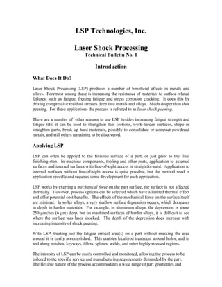
- 19. 19 in Figure 17b, with two overlapping spots. After treatment, the fatigue life was tripled from 33,000 cycles to 92,000 cycles. a. Untreated, Nf = 33,000 cycles. b. Laser shocked, Nf = 92,000 cycles. Figure 17. A 1026 steel part, locally laser shock peened to triple its fatigue life. Fatigue-limited metals, including pearlitic and ferritic malleable cast irons, and iron powder metallurgy materials show fatigue life improvements after laser shock peening. A comparison between LSP and shot peening is shown in Figure 18. This was performed on AF 1410 steel cylindrical test bars fatigue tested under flight spectrum loading. The LSP bar’s fatigue life was 56 percent longer than that of the unshocked bars, and 25 percent longer than that of the shot peened bars. Laser Shock Peened Shot peened As-machined AF 1410 Steel 4 0 2000 4000 6000 8000 1 10 Spectrum Flight Hrs to Failure Figure 18. Fatigue of AF 1410 Steel tested under Flight Spectrum loading conditions comparing shot peening and laser shock peening. Strength and Hardness By essentially cold working the surface of metals and alloys, LSP strain hardens the surface layer. An example of the surface hardness profile across a laser shocked spot is shown in Figure 19 for 2024-T351 aluminum.
- 20. 20 180 2024-T351 170 Hardness, DPH500 160 150 Baseline 140 Laser Shocked Region Hardness 130 0 0.2 0.4 0.6 0.8 1 1.2 Distance, inches Figure 19. Surface hardening across a laser shock peened spot in 2024-T351 aluminum. In 316 stainless steel the surface hardness was measured on spots given increasing numbers of multiple shots. The hardness increased continuously with additional shots as shown in Figure 20. Other alloys, such as 7075 aluminum and 2024-T8 aluminum did not show surface hardening under the laser shocking conditions investigated. This behavior reflects their relative strain hardening behavior and possibly dynamic yield strength. Surface strain hardening will be greater in materials with a higher strain hardening coefficient and lower dynamic yield strength. 450 400 Hardness, KHN 350 300 250 316 Stainless Steel 200 0 2 4 6 8 10 12 Number of Shots Figure 20. Increasing surface hardness of 316 stainless steel with increasing laser shock peening intensity.
- 21. 21 In thin sections, through-thickness hardening and over-all strengthening can be obtained after shocking from both sides with the split beam arrangement. This arises from two effects. One is the strain hardening of the surface layer and the other is hardening in the mid-thickness of the section from the local superposition of the shock waves from opposite surfaces. The last effect decreases with increasing thickness, becoming inconsequential in sections thicker than about 0.25 inches (6.3 mm). Two examples of this effect are shown in Figures 21 and 22. Figure 21 shows the hardness through the thickness of a 0.1-inch (2.54 mm) thick sheet of 2024-T351 after LSP. The base hardness was 140 VHN (Vickers hardness). The hardness gradually decreased below each surface as the peak pressure of the shock wave decreased. The bump in hardness in the mid-section where the shock waves traveling in opposite directions super-imposed is clearly evident. Figure 22 shows the increase in tensile yield strength of weld zones in two aluminum alloys, a work-hardening alloy, 5086-H32, and an age-hardening alloy, 6061-T6, after 170 2024-T351 Hardness, DPH500 160 150 Baseline Hardness 140 0 0.2 0.4 0.6 0.8 1 Front Back Surface Distance, mm Surface Figure 21. Through-thickness hardening in 2024-T351 aluminum after split-beam laser shock peening from both sides simultaneously. LSP of the weld and heat affected zones. The specimens were 0.120 inches (3 mm) thick when laser shocked. After LSP the 5086 alloy regained its parent metal strength, as would be expected in a work-hardening alloy. The 6061 alloy regained about half of the strength lost by welding. In this age-hardening alloy, restoring the remainder of the strength lost would require an aging heat treatment. From this response it is clear that LSP could be used to provide localized strain hardening and strengthening in metallic parts for selected applications.
- 22. 22 Parent Alloy As Welded 5086-H32 Welded and LSP Parent Alloy As Welded 6061-T6 Welded and LSP 0 10 20 30 40 50 0.2% Yield Strength, ksi Figure 22. The strengthening of weld and heat affected zones in aluminum alloys by laser shock peening. Stress Corrosion Cracking There is limited evidence that laser shock peening should be beneficial in increasing resistance to stress corrosion cracking. Since shot peening offers such improvement by producing residual compressive stresses in the surface, LSP should offer similar or more improvement due to the deeper compressive stresses. Applications of Laser Shock Processing Many of the potential applications of laser shock processing are based on laser shock peening for increased fatigue resistance. The initial applications being implemented for LSP are representative of those anticipated at this stage of development: processing high- value-added parts for improved performance, or using LSP to replace a traditional process or material to achieve a cost advantage. Applications which fall in these categories are aircraft engine parts, aircraft structures, medical implants and prostheses, components of power generation turbines and other turbines, specialized gears and parts in valves, and other mechanism components having notches, holes and corners prone to fatigue failure. With ongoing laser and process development, costs will continue to decrease rapidly, opening the way to an ever-broader range of applications including automotive gears, cams, rocker arms and connecting rods, tool bits, tooling and dies. In considering applications of LSP, it should not be viewed as a competitor to shot peening, but instead, as its complement. In many cases, LSP will be used alone where shot peening is not suitable or cannot be used for various reasons. These reasons could include better properties, treatment of difficult geometries, improved quality control, smoother finished surface, or ease of processing, to name a few. In other cases LSP will
- 23. 23 be used along with shot peening, to provide additional protection in fatigue critical regions. In addition to laser shock peening, there are potential uses in a variety of applications having nothing to do with fatigue, but instead based on the localized strain hardening or shock impact characteristics of the process. For example, localized surface plastic strain induced by shock impact could enhance diffusion bonding of small components, or similarly, a coating. The shock wave may be used to locally densify porous coatings, or to compact powders in unique situations. It may also be useful in unique metal forming operations or connector attachments. Quality Control Quality control issues for laser shock peening can be addressed in numerous ways. For example, a number of the laser beam parameters can be monitored and recorded for each shot in real time. In addition, there are process parameters that can be monitored using features on the material surface, measurement of material properties, or other characteristics of the process. Periodic checks can be made by sampling the residual stress distributions and property changes in processed parts. Many of these process-related parameters can be measured and used to control the process in real time. For these, acceptable limits of their values can be defined, and corrections made immediately if they drift outside of these limits during processing. References 1. C. Lykins, P. Prevey, and P. Mason, Laser Shock Peened Compressive Residual Profile After Exposure to Temperature, AF Report WL-TR-95-2108, September, 1995, Wright Patterson AFB, OH. 2. C. O. Lykins, “Laser Shock Peening vs. Shot Peening, A Damage Tolerance Investigation”, Proceedings Surface Treatment of Titanium Alloys, Cincinnati, OH, October, 1996. The rest of the information presented in this report has been taken from the following papers and reports. A. H. Clauer, B. P. Fairand and B. A. Wilcox, “Laser Shock hardening of weld Zones in Aluminum Alloys”, Metallurgical Transactions A, 8A, 1871-1876 (December, 1977). A. H. Clauer and B. P. Fairand, “Interaction of Laser-Induced Stress Waves With Metals”, Applications of Lasers in Materials Processing, ed. by E. Metzbower, ASM, Metals Park, OH (1979).
- 24. 24 A. H. Clauer, B. P. Fairand, and J. Holbrook, “Effects of Laser-Induced Shock Waves on Metals”, Shock Waves and High Strain Rate Phenomena in Metals, ed. by M. A. Meyers and L. E. Murr, Plenum Press, New York (1981), pp. 675-702. A. H. Clauer, C. T. Walters, and S. C. Ford, “The Effects of Laser Shock Processing on the Fatigue Properties of 2024-T3 Aluminum”, Lasers in Materials Processing, ASM, Metals Park, OH (1983) pp. 7-22. T. R. Tucker and A. H. Clauer, Laser Processing of Materials, Report MCIC-83-48, Metals and Ceramics Information Center, Columbus, OH (November, 1983). Laser Shock Processing Increases the Fatigue Life of Metal Parts, Materials and Processing Report, 6, (6), 3 (September, 1991). LSP Technologies, Inc. is interested in helping you with your fatigue and other product problems that can be solved using laser shock peening or laser shock processing. Please Contact: David W. Sokol LSP Technologies, Inc. 6145 Scherers Place Dublin, OH 43016-1284 Phone: (614) 718-3000 Ext. 14 Fax: (614) 718-3007 e-mail: dsokol@lspt.com