SlideShare a Scribd company logo
1 of 18
Download to read offline
Class Note, Optical Fiber Communication (Chapter 1), By: Krishna Prasad Phelu Pg. 1/18
Chapter 1 Optical Fibers: Introduction
Introduction to Optical Fiber Communication
 Communication system with light as the carrier and fiber as a communication medium.
 ‘Light’ for communication has been used for signal fires, reflecting mirrors, signaling lamps like light-
house but limited information transfer.
 Light is an EM wave that can be detected.
 As carrier frequency increases, bandwidth increase and data rate increases.
 Operates at wavelength 800nm to 1700nm
Need for Fiber-Optic Communications
(Ref: Govind P. Agrawal)
The advent of telegraphy in the 1830s replaced the use of light by electricity and began the era of electrical
communications. Telegraphy used essentially a digital scheme through two electrical pulses of different durations
(dots and dashes of the Morse code). The bit rate, B, could be increased to∼10 b/s by the use of new coding
techniques, such as the Morse code. The use of intermediate relay stations allowed communication over long
distances (∼1000 km).
The invention of the telephone in 1876 brought a major change inasmuch as electric signals were transmitted in
analog form through a continuously varying electric current. Analog electrical techniques were to dominate
communication systems for a century or so.
The use of coaxial cables in place of wire pairs increased system capacity considerably. The bandwidth of such
systems is limited by the frequency-dependent cable losses, which increase rapidly for frequencies beyond 10
MHz.
This limitation led to the development of microwave communication systems in which an electromagnetic carrier
wave with frequencies in the range of 1–10 GHz is used to transmit the signal by using suitable modulation
techniques.
The first coaxial-cable system, put into service in 1940, was a 3-MHz system capable of transmitting 300 voice
channels or a single television channel. The first microwave system operating at the carrier frequency of 4 GHz
was put into service in 1948. Since then, both coaxial and microwave systems have evolved considerably.
A commonly used figure of merit for communication
systems is the bit rate–distance product, BL, where B is the
bit rate and L is the repeater spacing.
It was realized during the second half of the twentieth
century that an increase of several orders of magnitude in
the BL product would be possible if optical waves were
used as the carrier.
Class Note, Optical Fiber Communication (Chapter 1), By: Krishna Prasad Phelu Pg. 2/18
However, neither a coherent optical source nor a suitable transmission medium was available during the 1950s.
 The invention of the laser and its demonstration in 1960 solved the first problem.
 It was suggested in 1966 that optical fibers might be the best choice, as they are capable of guiding the
light in a manner similar to the guiding of electrons in copper wires.
The main problem was the high losses of optical fibers - fibers available during the 1960s had losses in excess of
1000 dB/km. A breakthrough occurred in 1970 when fiber losses could be reduced to below 20 dB/km in the
wavelength region near 1µm. The commercial deployment of lightwave systems followed the research and
development phase closely. As a result, the bit rate–distance product of modern lightwave systems can exceed
by a factor of 107
compared with the first-generation lightwave systems.
Optical Fiber Communication system block diagram
(Ref: John M. Senior)
An optical fiber communication system is similar in basic concept to general communication system. The
function of communication system is to convey the signal from the information source over the transmission
medium to the destination. The communication system therefore consists of a transmitter or modulator linked to
the information source, the transmission medium, and a receiver or demodulator at the destination point.
In electrical communications the information source provides an electrical signal, usually derived from a message
signal which is not electrical (e.g. sound), to a transmitter comprising electrical and electronic components which
converts the signal into a suitable form for propagation over the transmission medium. This is often achieved by
modulating a carrier, which, may be an electromagnetic wave. The transmission medium can consist of a pair of
wires, a coaxial cable or a radio link through free space down which the signal is transmitted to the receiver,
where it is transformed into the original electrical information signal (demodulated) before being passed to the
destination.
For optical fiber communications the system, the information source provides signal to a transmitter comprising
an electrical stage which drives an optical source to give modulation of the lightwave carrier. The optical source
which provides the electrical–optical conversion may be either a semiconductor laser or light-emitting diode
Class Note, Optical Fiber Communication (Chapter 1), By: Krishna Prasad Phelu Pg. 3/18
(LED). The transmission medium consists of an optical fiber cable and the receiver consists of an optical detector
which drives a further electrical stage and hence provides demodulation of the optical carrier. Photodiodes (p–n,
p–i–n or avalanche) and, in some instances, phototransistors and photoconductors are utilized for the detection
of the optical signal and the optical–electrical conversion.
Thus there is a requirement for electrical interfacing at either end of the optical link and at present the signal
processing is usually performed electrically. But, significant developments have taken place in devices for optical
signal processing which are starting to alter this situation.
The optical carrier may be modulated using either an analog or digital information signal. Analog modulation
involves the variation of the light emitted from the optical source in a continuous manner. With digital
modulation, however, discrete changes in the light intensity are obtained (i.e. on–off pulses). Although often
simpler to implement, analog modulation with an optical fiber communication system is less efficient, requiring
a far higher signal-to-noise ratio at the receiver than digital modulation. Also, the linearity needed for analog
modulation is not always provided by semiconductor optical sources, especially at high modulation frequencies.
For these reasons, analog optical fiber communication links are generally limited to shorter distances and lower
bandwidth operation than digital links.
Following figure shows a block schematic of a typical digital optical fiber link:
Initially, the input digital signal from the information source is suitably encoded for optical transmission. The
laser drive circuit directly modulates the intensity of the semiconductor laser with the encoded digital signal.
Hence a digital optical signal is launched into the optical fiber cable. The avalanche photodiode (APD) detector
is followed by a front-end amplifier and equalizer or filter to provide gain as well as linear signal processing and
noise bandwidth reduction. Finally, the signal obtained is decoded to give the original digital information.
Repeaters can be used for long distance digital communication system. They convert weak and distorted optical
signals to electrical signals and then regenerate original digital pulse train for further transmission. In long
systems numerous amplifiers and repeaters may be used.
Advantages of optical fiber communication
(Ref: John M. Senior)
Communication using an optical carrier wave guided along a glass fiber has a number of extremely attractive
features:
a) Enormous potential bandwidth.
The optical carrier frequency in the range 1013
to 1016
Hz yields a far greater potential transmission bandwidth
than metallic cable systems (i.e. coaxial cable bandwidth typically around 20 MHz over distances up to a
maximum of 10 km) or even millimeter wave radio systems (i.e. systems currently operating with modulation
bandwidths of 700 MHz over a few hundreds of meters).
Class Note, Optical Fiber Communication (Chapter 1), By: Krishna Prasad Phelu Pg. 4/18
Indeed, by the year 2000 the typical bandwidth - length product for an optical fiber link incorporating fiber
amplifiers was 5000 GHz km in comparison with the typical bandwidth–length product for coaxial cable of
around 100 MHz km. Hence optical fiber was already demonstrating a factor of 50000 bandwidth – length
improvement over coaxial cable while also providing this superior information-carrying capacity over much
longer transmission distances.
Use of wavelength division multiplexed (WDM) operation can further enhanced bandwidth utilization of an
optical fiber.
b) Small size and weight
Optical fibers have very small diameters which are often no greater than the diameter of a human hair. Hence,
even when such fibers are covered with protective coatings they are far smaller and much lighter than
corresponding copper cables.
Hence optical fibers are portable, easy for ducting and installation as well as suitable for an expansion of signal
transmission within aircraft, satellites and even ships.
c) Electrical isolation
Optical fibers which are fabricated from glass, or sometimes a plastic polymer, are electrical insulators and
therefore there is no arcing, spark or short circuit hazard.
d) Immunity to interference and crosstalk
Optical fibers form a dielectric waveguide and are therefore free from electromagnetic interference (EMI), radio-
frequency interference (RFI), or switching transients giving electromagnetic pulses (EMPs). Hence
 The operation of an optical fiber communication system is unaffected by transmission through an
electrically noisy environment
 The fiber cable requires no shielding from EMI.
 The fiber cable is also not susceptible to lightning strikes if used overhead rather than underground.
 No optical interference between fibers and hence, unlike communication using electrical conductors,
crosstalk is negligible, even when many fibers are cabled together.
e) Increased Signal security
The light from optical fibers does not radiate significantly and therefore they provide a high degree of signal
security. Unlike the situation with copper cables, a transmitted optical signal cannot be obtained from a fiber in
a noninvasive manner (i.e. without drawing optical power from the fiber). If the cable is tapped, it’s very easy to
monitor because the cable leaks light, causing the entire system to fail.
Therefore, in theory, any attempt to acquire a message signal transmitted optically may be detected. This feature
is obviously attractive for military, banking and general data transmission (i.e. computer network) applications.
f) Low transmission loss
Optical fiber cables which exhibit very low attenuation or transmission loss in comparison with the copper
conductors. Fibers have been fabricated with losses as low as 0.15 dB km−1
. It facilitates the implementation of
communication links with extremely wide optical repeater or amplifier spacings, thus reducing both system cost
and complexity.
g) System reliability and ease of maintenance
Due to low-loss property of optical fiber cables, requirement for intermediate repeaters reduces. Hence with fewer
optical repeaters or amplifiers, system reliability is generally enhanced in comparison with conventional electrical
conductor systems.
Class Note, Optical Fiber Communication (Chapter 1), By: Krishna Prasad Phelu Pg. 5/18
h) Potential low cost
The glass which generally provides the optical fiber transmission medium is made from sand – not a scarce
resource. So, in comparison with copper conductors, optical fibers offer the potential for low-cost line
communication for bulk purchases. Overall system costs when utilizing optical fiber communication on long-
haul links are substantially less than those for equivalent electrical line systems because of the low-loss and
wideband properties of the optical transmission medium.
Although optical fiber transmission medium has become competitive with copper wires (i.e. twisted pairs), it has
not yet been achieved in all the other component areas associated with optical fiber communications. For
example, the costs of high-performance semiconductor lasers and detector photodiodes are still relatively high,
as well as some of those concerned with the connection technology (demountable connectors, couplers, etc.).
Basic laws and definitions
(Ref: G. Keiser and John M. Senior)
Refractive index
To consider the propagation of light within an optical fiber utilizing the ray theory model it is necessary to take
account of the refractive index of the dielectric medium. The refractive index of a medium is defined as the ratio
of the velocity of light in a vacuum to the velocity of light in the medium. A ray of light travels more slowly in
an optically dense medium than in one that is less dense, and the refractive index gives a measure of this effect.
In free space a light wave travels at a speed c = 3 x 10⁸
m/s. Upon entering a dielectric or non-conducting medium
the wave now travels at a speed v, which is characteristic of the material and is less than c. The ratio of speed of
c to v is the index of refraction n of the material,
Typical values of n are 1.00 for air, 1.33 for water, 1.50 for glass, and 2.42 for diamond.
Reflection and Refraction
Class Note, Optical Fiber Communication (Chapter 1), By: Krishna Prasad Phelu Pg. 6/18
When light traveling in a certain medium is reflected off an optically denser material (one with a higher refractive
index), the process is referred to as external reflection. Conversely, the reflection of light off of less optically
dense material (such as light traveling in glass being reflected at a glass-to-air interface) is called internal
reflection.
Total internal reflection
Consider a ray approaching the interface is propagating in a dielectric of refractive index n1 and is at an angle ϕ1
to the normal at the surface of the interface. If the dielectric on the other side of the interface has a refractive
index n2 which is less than n1, then the refraction is such that the ray path in this lower index medium is at an
angle ϕ2 to the normal, where ϕ2 is greater than ϕ1.
From Snell’s law of refraction:
Or:
Class Note, Optical Fiber Communication (Chapter 1), By: Krishna Prasad Phelu Pg. 7/18
As n1 is greater than n2, the angle of refraction is always greater than the angle of incidence. As angle of incidence
becomes greater, the angle of refraction also goes on increasing. When the angle of refraction is 90° and the
refracted ray emerges parallel to the interface between the dielectrics, the angle of incidence must be less than
90°. This is the limiting case of refraction and the angle of incidence is now known as the critical angle ϕc. The
value of the critical angle is given by1
:
At angles of incidence greater than the critical angle on refraction is possible and the light is reflected back into
the originating dielectric medium (total internal reflection) with high efficiency (around 99.9%). Hence, total
internal reflection occurs at the interface between two dielectrics of differing refractive indices when light is
incident on the dielectric of lower index from the dielectric of higher index, and the angle of incidence of the ray
exceeds the critical value.
This is the mechanism by which light propagate down an optical fiber with low loss. Transmission of a light ray
in an optical fiber via a series of total internal reflections at the interface of the silica core and the slightly lower
refractive index silica cladding is shown in figure below. The ray has an angle of incidence ϕ at the interface
which is greater than the critical angle and is reflected at the same angle to the normal.
1
Sin(900
) = 1
Class Note, Optical Fiber Communication (Chapter 1), By: Krishna Prasad Phelu Pg. 8/18
The light ray shown in above Figure is known as a Meridional ray as it passes through the axis of the fiber core.
This type of ray is the simplest to describe and is generally used when illustrating the fundamental transmission
properties of optical fibers. Another possible ray in optical fiber is Skew ray. A skew ray is a ray that travels in a
non-planar zig-zag helical path which neither pass through the fiber axis nor parallel to the fiber axis.
Any discontinuities or imperfections at the core–cladding interface would probably result in refraction rather than
total internal reflection, with the subsequent loss of the light ray into the cladding.
Acceptance angle
Not all rays entering the fiber core will continue to be propagated down its length. Only rays with a sufficiently
shallow grazing angle (i.e. with an angle to the normal greater than ϕc) at the core–cladding interface are
transmitted by total internal reflection. The geometry concerned with launching a light ray into an optical fiber
is shown in Figure below, which illustrates a meridional ray A at the critical angle ϕc within the fiber at the core–
cladding interface. Ray A enters the fiber core at an angle θa to the fiber axis and is refracted at the air–core
interface before transmission to the core–cladding interface at the critical angle.
Any rays (B) which are incident into the fiber core at an angle greater than θa will be transmitted to the core–
cladding interface at an angle less than ϕc, and will not be totally internally reflected rather than it is refracted
into the cladding and eventually lost by radiation.
Thus for rays to be transmitted by total internal reflection within the fiber core they must be incident on the fiber
core within an acceptance cone defined by the conical half angle θa. Hence θa is the maximum angle to the axis
Class Note, Optical Fiber Communication (Chapter 1), By: Krishna Prasad Phelu Pg. 9/18
at which light may enter the fiber in order to be propagated, and is often referred to as the acceptance angle for
the fiber.
Numerical aperture
We can to continue the ray theory analysis to obtain a relationship between the acceptance angle and the
refractive indices of the three media involved, namely the core, cladding and air. This leads to the definition of a
more generally used term, the numerical aperture of the fiber.
Consider light ray incident on the fiber core at an angle θ1 to the fiber axis which is less than the acceptance
angle for the fiber θa.
The ray enters the fiber from a medium (air) of refractive index n0, and the fiber core has a refractive index n1,
which is slightly greater than the cladding refractive index n2. Assuming the entrance face at the fiber core to be
normal to the axis.
Consider the refraction at the air–core interface and using Snell’s law given by:
Considering the right-angled triangle ABC in above figure:
where ϕ is greater than the critical angle at the core–cladding interface. Substituing θ2 in Snell’s law equation2
,
Using the trigonometrical relationship sin2
X+cos2
X=1,
When the limiting case for total internal reflection is considered, ϕ becomes equal to the critical angle, ϕc, for the
core–cladding interface which is sinϕc=n2/n1. Also in this limiting case θ1 becomes the acceptance angle for the
fiber θa. With these substitutions,
Numerical Aperture (NA) is defined as:
2
sin(pi/2 - X) = cosX
Class Note, Optical Fiber Communication (Chapter 1), By: Krishna Prasad Phelu Pg. 10/18
Since the NA is often used with the fiber in air where n0 is unity, it is simply equal to sinθa. It may also be noted
that incident meridional rays over the range 0 ≤θ1≤θa will be propagated within the fiber.
Acceptance angle in air for the fiber can be calculated as,
The NA may also be given in terms of the relative refractive index difference Δ between the core and the cladding
which is defined as:
Taking under root,
Hence NA we can also be write as:
for Δ<<1,
The numerical aperture is a very useful measure of the light-collecting ability of a fiber. They are independent of
the fiber core diameter and will hold for diameters as small as 8μm. However, for smaller diameters they break
down as the geometric optics approach is invalid. This is because the ray theory model is only a partial description
of the character of light.
Question 1: A silica optical fiber with a core diameter large enough to be considered by ray theory analysis has
a core refractive index of 1.50 and a cladding refractive index of 1.47. Determine:
(a) the critical angle at the core–cladding interface;
(b) the NA for the fiber;
(c) the acceptance angle in air for the fiber.
Solution:
a) The critical angle ϕc at the core–cladding interface is given by,
b) The NA is:
c) The acceptance angle in air θa is given by:
Class Note, Optical Fiber Communication (Chapter 1), By: Krishna Prasad Phelu Pg. 11/18
Question 1: A typical relative refractive index difference for an optical fiber designed for long distance
transmission is 1%. Estimate the NA in air for the fiber when the core index is 1.46. Further, calculate the critical
angle at the core–cladding interface within the fiber. It may be assumed that the concepts of geometric optics
hold for the fiber.
Solution:
Relative refractive index difference, Δ=0.01
So, the NA is
The relative refractive index difference Δ gives:
Hence,
The critical angle at the core–cladding interface is:
Numerical aperture for Skew rays
Skey ray is transmitted without passing through the fiber axis and following a helical path through the fiber.
The helical path traced through the fiber gives a change in direction of 2γ at each reflection, where γ is the angle
between the projection of the ray in two dimensions and the radius of the fiber core at the point of reflection.
In order to calculate the acceptance angle for a skew ray it is necessary to define the direction of the ray in two
perpendicular planes. The geometry of the situation is illustrated in Figure below where a skew ray is shown
incident on the fiber core at the point A, at an angle θs to the normal at the fiber end face. The ray is refracted at
the air–core interface before traveling to the point B in the same plane. The angles of incidence and reflection at
the point B are ϕ, which is greater than the critical angle for the core–cladding interface.
Class Note, Optical Fiber Communication (Chapter 1), By: Krishna Prasad Phelu Pg. 12/18
When considering the ray between A and B it is necessary to resolve the direction of the ray path AB to the core
radius at the point B. As the incident and reflected rays at the point B are in the same plane, this is simply cosϕ.
To find another resolution, γ is the angle between the core radius (BR) and the projection of the ray AB onto a
plane BRT normal to the core axis (BT). And θ is the angle between the ray and a line AT drawn parallel to the
core axis. Thus to resolve the ray path AB relative to the radius BR requires multiplication by cos γ and sin θ.
Both of these resolution are that of the same ray AB. So, they should be equal
Using the trigonometrical relationship, sin2
X+cos2
X=1.
If the limiting case for total internal reflection is now considered, then ϕ becomes equal to the critical angle ϕc
for the core–cladding interface and sinϕc = n2/n1. So above equation can be written as,
Above equation is shown as inequality because here ϕ is specified for limiting case of critical angle ϕc but θ is
not specified for limiting case.
Furthermore, using Snell’s law at the point A,
where θa represents the maximum input axial angle for meridional rays and θ is the internal axial angle.
Substituting for sin θ from above equation gives:
where θas now represents the maximum input angle or acceptance angle for skew rays. It may be noted that the
inequality shown previously is no longer necessary as all the terms are specified for the limiting case.
Thus the acceptance conditions for skew rays are:
and in the case of the fiber in air (n0=1):
Class Note, Optical Fiber Communication (Chapter 1), By: Krishna Prasad Phelu Pg. 13/18
Comparisons between meridional ray and skew ray
Comparing NA for meridional rays and skew rays, it may be noted that skew rays are accepted at larger axial
angles in a given fiber than meridional rays, depending upon the value of cos γ.
For cos γ is equal to unity and θas = θa which represents meridional rays. Thus θa is the maximum conical half
angle for the acceptance of meridional rays and it defines the minimum input angle for skew rays.
Skew rays tend to propagate only in the annular region near the outer surface of the core, and do not fully utilize
the core as a transmission medium.
Skew rays increase the light-gathering capacity of the fiber. This increased light-gathering ability may be
significant for large NA fibers, but for most communication design purposes the meridional rays are considered
adequate.
Question 3: An optical fiber in air has an NA of 0.4. Compare the acceptance angle for meridional rays with that
for skew rays which change direction by 100° at each reflection.
Solution:
The acceptance angle for meridional rays with n0=1 is:
The skew rays change direction by 100° at each reflection, therefore γ=50°. Hence the acceptance angle for skew
rays is:
Optical Fiber
(Ref: G. Keiser)
Structure of Optical Fiber
Optical fiber acts as a waveguide or light pipe. It is a single solid dielectric cylinder of radius ‘a’ and index of
refraction n1 as shown in figure below. This cylinder is known as the core of fiber. The core is surrounded by
solid dielectric cladding having a refractive index n2 that is less than n1.
In low-loss and medium-loss fiber core is made from glass and cladding is made from either glass or plastic. But
high loss fiber is made from plastic-core and plastic cladding.
In principle cladding is not necessary for light to propagate along the core of the fiber, it serves several purposes:
 Reduces scattering loss of light resulting from dielectric discontinuities from the core into the surrounding
air
 Adds mechanical strength
 Protects the core from absorbing surface contaminants.
Cladding is further encapsulated in an elastic plastic material called buffer coating. It adds further strength to the
fiber and mechanically isolates or buffers the fibers from small geometrical irregularities, distortions or
Class Note, Optical Fiber Communication (Chapter 1), By: Krishna Prasad Phelu Pg. 14/18
roughnesses of adjacent surfaces. These perturbations could otherwise cause scattering losses induced by random
microscopic bends on installation.
Types of Optical fiber
On the basis of core-cladding refractive index profile
a) Step Index
b) Graded Index
On the basis of number of modes supported
a) Single mode
b) Multi Mode
Step Index Fiber
The optical fiber with a core of constant refractive index n1 and a cladding of a slightly lower refractive index n2
is known as step index fiber. This is because the refractive index profile for this type of fiber makes a step
change at the core–cladding interface.
The refractive index profile may be defined as:
Graded index fibers
Graded index fibers do not have a constant refractive index in the core but a decreasing core index n(r) with
radial distance from a maximum value of n1 at the axis to a constant minimum value n2 beyond the core radius
‘a’ in the cladding.
This index variation may be represented as:
Where,
Class Note, Optical Fiber Communication (Chapter 1), By: Krishna Prasad Phelu Pg. 15/18
Δ= (n1-n2)/n1, is the relative refractive index difference and
α is the profile parameter which gives the characteristic refractive index profile of the fiber core
Refractive index profile of the fiber core can be expressed as a variation of α
 When α=∞ it represents the step index profile
 When α=2 it represents a parabolic profile
 When α=1 it represents a triangular profile
Single Mode Fiber (SMF)
Single mode fiber sustains only one fundamental mode of light propagation. Single mode the fiber is designed to
allow propagation of only one mode, while all other modes are attenuated by leakage or absorption. Single mode
fiber has small core size and the index of refraction between the core and the cladding changes less than it does
for multimode fibers. Widely deployed single-mode fibers employ a step index profile design.
Advantages of single mode fiber
 They exhibit the greatest transmission bandwidths and the lowest losses of the fiber transmission media.
 They have a superior transmission quality over other fiber types because of the absence of modal noise.
 Suitable for long distance transmission.
Multimode Fiber
Multimode fiber has a larger core diameter than that of single mode fiber, which is large enough to allow the
propagation of many modes within the fiber core simultaneously. When one pulse of signal is generated into
multimode fiber the multiple modes enter the fiber core from different angles and each modes propagates at
different speeds and causes pulse broadening (modal dispersion). Generally it is used for short and medium
distance.
Multimode step index fiber has a core diameter of around 50μm or greater. It allows many different possible
ray paths through the fiber. In multimode step index fiber considerable dispersion may occur due to the differing
Class Note, Optical Fiber Communication (Chapter 1), By: Krishna Prasad Phelu Pg. 16/18
group velocities of the propagating modes. This in turn restricts the maximum bandwidth attainable with
multimode step index fibers, especially when compared with single-mode fibers.
Multimode Graded-Index fiber contains a core in which the refractive index diminishes gradually from the
center axis out toward the cladding. The meridional rays appear to follow curved paths through the graded index
multimode fiber core rather than zigzagging off the cladding. Using the concepts of geometric optics, the gradual
decrease in refractive index from the center of the core creates many refractions of the rays as they are effectively
incident on a large number of high to low index interfaces. As a result ray is gradually curved and the ray travels
back towards the core axis, again being continuously refracted.
Multimode graded index fibers exhibit far less intermodal dispersion than multimode step index fibers due to
their refractive index profile. The rays traveling close to the fiber axis have shorter paths when compared with
rays which travel into the outer regions of the core. However, the near axial rays are transmitted through a region
of higher refractive index and therefore travel with a lower velocity than the more extreme rays. This compensates
for the shorter path lengths and reduces dispersion in the fiber.
Hence, multimode graded index fibers with parabolic or near-parabolic index profile cores have transmission
bandwidths which may be orders of magnitude greater than multimode step index fiber bandwidths.
Following table shows the different types of fibers and their dispersive characteristics.
Advantages of Multimode Fiber
 The larger core radii of multimode fibers make it easier to launch optical power into the fiber
 Lower tolerance required in fiber joints.
 Light can be launched into a multimode fiber using a light emitting diode (LED) source, whereas single-
mode fibers must generally be exited with laser diodes. Although LEDs have less optical output power
than laser diodes they are easier to make, are less expensive, require less complex circuitry, and have
longer lifetimes than laser, thus making them more desirable in many applications.
Class Note, Optical Fiber Communication (Chapter 1), By: Krishna Prasad Phelu Pg. 17/18
Disadvantage of Multimode Fiber
 Multimode fiber suffer from intermodal dispersion where as in single mode fibers intermodal dispersion
effects are not present. When an optical pulse is launched into a fiber, the optical power in the pulse is
distributed over all of the modes of the fiber. Each modes that can propagate in a multimode fiber travels
at a slightly different velocity. This means that the modes in a given optical pulse arrive at the fiber end
at slightly different times, thus causing the pulse to spread out in time as it travels along the fiber.
o This effect can be reduced by using a graded index profile in the fiber core.
Application of OFC:
Fiber optics has tremendous application in every part of life and several such applications have already been
implemented in practice to varying degrees. Some of detailed applications are as follows:
1. Telecommunication/Telephone applications:- The various applications of fiber optics in the
telecommunication area in general could be in voice telephone, video phones, various new services,
messages services and data networks all transmitted over the common carrier link.
2. Military application:- These include communication, command and control links on ships and
aircraft, data links for satellite earth stations and under sea system for which EMI effect, weight and size,
signal leakage and attenuation plays a major role. OFC systems meet this requirement.
3. Space application:- Optical fibers offer the following significant advantages for space environment
;namely high bandwidth( greater than 1 Ghz as compared to 1 Mhz for twisted pair), noise immunity,
inherent radiation, reduce weight (90% weight savings over conventional wire system), low bit error
rate, size and volume reduction, EMI immunity and lower cost.
4. Sensor application:- A fiber optic sensor consists of a length of a fiber that modulates the light passing
though it when exposed to the changing environment one wants to sense. The physical effects
exposed to the environment lead to changes in frequency, intensity and polarization of light and thus
cause variation in the resultant optical signal.
5. Under sea transmission cables:- Coaxial under sea cable systems have been used as one of the major
transmission systems in international telecommunication networks over the past 25 years. But this
system has nearly reached a limit in its ability to increase the capacities. Therefore optical fiber under sea
cable system are considered to be very promising technology to over come these barriers.
6. Broad band applications: Application that are primilarly broadband services include broadcast tv, cable
tv (CTV, community antenna television), remote monitory, and surveillance system.
Class Note, Optical Fiber Communication (Chapter 1), By: Krishna Prasad Phelu Pg. 18/18
7. Computer application:- Fiber system are particularly suited for transmission of digital data, such as that
generated by the computers. Interconnections can be made between CPU and memories, CPU and
peripherals and between CPUs.
8. OFC for electric power companies:- Electric power companies are progressively installing the OFC
system for power system protections, supervision and control, measurements etc.
9. Miscellaneous:- These include biomedical applications. General home appliances application. Small
office building and so on.

More Related Content

What's hot

Types of optical fiber
Types of optical fiberTypes of optical fiber
Types of optical fiberBala V
 
Optical fiber communication Part 1 Optical Fiber Fundamentals
Optical fiber communication Part 1 Optical Fiber FundamentalsOptical fiber communication Part 1 Optical Fiber Fundamentals
Optical fiber communication Part 1 Optical Fiber FundamentalsMadhumita Tamhane
 
Optical Fibre Splices , Couplers and Connectors
Optical Fibre Splices , Couplers and ConnectorsOptical Fibre Splices , Couplers and Connectors
Optical Fibre Splices , Couplers and ConnectorsRitwikSaurabh1
 
Chapter6 optical sources
Chapter6 optical sourcesChapter6 optical sources
Chapter6 optical sourcesvijju005
 
Optical time domain Reflectometer
Optical time domain ReflectometerOptical time domain Reflectometer
Optical time domain ReflectometerNaveen Kumar
 
transmission-line-and-waveguide-ppt
transmission-line-and-waveguide-ppttransmission-line-and-waveguide-ppt
transmission-line-and-waveguide-pptATTO RATHORE
 
Photo detector noise
Photo detector noisePhoto detector noise
Photo detector noiseGec bharuch
 
Final thesis paper Digital Optical fiber link design
Final thesis paper Digital Optical fiber link designFinal thesis paper Digital Optical fiber link design
Final thesis paper Digital Optical fiber link designMd. Nadimul Islam
 
Link power and rise time budget analysis
Link power and rise time budget analysisLink power and rise time budget analysis
Link power and rise time budget analysisCKSunith1
 
Splicing of optical fiber
Splicing of optical fiberSplicing of optical fiber
Splicing of optical fiberBala V
 

What's hot (20)

microwave-tubes
 microwave-tubes microwave-tubes
microwave-tubes
 
Types of optical fiber
Types of optical fiberTypes of optical fiber
Types of optical fiber
 
Optical fiber communication Part 1 Optical Fiber Fundamentals
Optical fiber communication Part 1 Optical Fiber FundamentalsOptical fiber communication Part 1 Optical Fiber Fundamentals
Optical fiber communication Part 1 Optical Fiber Fundamentals
 
Optical Fibre Splices , Couplers and Connectors
Optical Fibre Splices , Couplers and ConnectorsOptical Fibre Splices , Couplers and Connectors
Optical Fibre Splices , Couplers and Connectors
 
Optical fibres
Optical fibresOptical fibres
Optical fibres
 
Antenna Basics
Antenna BasicsAntenna Basics
Antenna Basics
 
S parameters
S parametersS parameters
S parameters
 
wave-guides
wave-guideswave-guides
wave-guides
 
Chapter6 optical sources
Chapter6 optical sourcesChapter6 optical sources
Chapter6 optical sources
 
Optical time domain Reflectometer
Optical time domain ReflectometerOptical time domain Reflectometer
Optical time domain Reflectometer
 
transmission-line-and-waveguide-ppt
transmission-line-and-waveguide-ppttransmission-line-and-waveguide-ppt
transmission-line-and-waveguide-ppt
 
Photo detector noise
Photo detector noisePhoto detector noise
Photo detector noise
 
Optical communication
Optical communicationOptical communication
Optical communication
 
Final thesis paper Digital Optical fiber link design
Final thesis paper Digital Optical fiber link designFinal thesis paper Digital Optical fiber link design
Final thesis paper Digital Optical fiber link design
 
Losses in fiber
Losses in fiberLosses in fiber
Losses in fiber
 
waveguides-ppt
waveguides-pptwaveguides-ppt
waveguides-ppt
 
Link power and rise time budget analysis
Link power and rise time budget analysisLink power and rise time budget analysis
Link power and rise time budget analysis
 
Microstrip Antennas
Microstrip AntennasMicrostrip Antennas
Microstrip Antennas
 
Antenna (2)
Antenna (2)Antenna (2)
Antenna (2)
 
Splicing of optical fiber
Splicing of optical fiberSplicing of optical fiber
Splicing of optical fiber
 

Similar to Optical Fiber Communication Chapter 1 Introduction

Communication Engineering
Communication EngineeringCommunication Engineering
Communication EngineeringMD. ABU OSMAN
 
Fiber optic communication
Fiber optic communicationFiber optic communication
Fiber optic communicationvishal gupta
 
01-Overview of Optical Fiber Communication.pptx
01-Overview of Optical Fiber Communication.pptx01-Overview of Optical Fiber Communication.pptx
01-Overview of Optical Fiber Communication.pptxAkliluAyele3
 
Performance analysis of different loss
Performance analysis of different lossPerformance analysis of different loss
Performance analysis of different losscaijjournal
 
Jaimin chp-2 - 2011 batch
Jaimin   chp-2  - 2011 batchJaimin   chp-2  - 2011 batch
Jaimin chp-2 - 2011 batchJaimin Jani
 
Transmission Media
Transmission MediaTransmission Media
Transmission MediaMunish Kumar
 
Physical communication media
Physical communication mediaPhysical communication media
Physical communication mediaAshvini Soni
 
Presentation on railways
Presentation on railwaysPresentation on railways
Presentation on railwaysNaughattyy Poem
 
Transmission media
Transmission mediaTransmission media
Transmission mediakinish kumar
 
Communication channel and networktechnologies.pdf
Communication channel and networktechnologies.pdfCommunication channel and networktechnologies.pdf
Communication channel and networktechnologies.pdfmouizakhan4
 
Communication - Line Communication Class 12 Part-6
Communication - Line Communication Class 12 Part-6Communication - Line Communication Class 12 Part-6
Communication - Line Communication Class 12 Part-6Self-employed
 
fiber optic communication basics and terminologies
fiber optic communication basics and terminologiesfiber optic communication basics and terminologies
fiber optic communication basics and terminologiesSaiyma Fatima Raza
 
6_line_communication.ppt
6_line_communication.ppt6_line_communication.ppt
6_line_communication.pptAKCreation22
 
Transmission Media
Transmission MediaTransmission Media
Transmission MediaSourav Roy
 

Similar to Optical Fiber Communication Chapter 1 Introduction (20)

Communication Engineering
Communication EngineeringCommunication Engineering
Communication Engineering
 
OPTICAL COMMUNICATION
OPTICAL COMMUNICATIONOPTICAL COMMUNICATION
OPTICAL COMMUNICATION
 
Thesis sdh
Thesis sdhThesis sdh
Thesis sdh
 
Fiber optic communication
Fiber optic communicationFiber optic communication
Fiber optic communication
 
Fiber Optics.pptx
Fiber Optics.pptxFiber Optics.pptx
Fiber Optics.pptx
 
01-Overview of Optical Fiber Communication.pptx
01-Overview of Optical Fiber Communication.pptx01-Overview of Optical Fiber Communication.pptx
01-Overview of Optical Fiber Communication.pptx
 
Rothmans
RothmansRothmans
Rothmans
 
Rothman
RothmanRothman
Rothman
 
Performance analysis of different loss
Performance analysis of different lossPerformance analysis of different loss
Performance analysis of different loss
 
Jaimin chp-2 - 2011 batch
Jaimin   chp-2  - 2011 batchJaimin   chp-2  - 2011 batch
Jaimin chp-2 - 2011 batch
 
Transmission Media
Transmission MediaTransmission Media
Transmission Media
 
Physical communication media
Physical communication mediaPhysical communication media
Physical communication media
 
Slide _OFC_1.pptx
Slide _OFC_1.pptxSlide _OFC_1.pptx
Slide _OFC_1.pptx
 
Presentation on railways
Presentation on railwaysPresentation on railways
Presentation on railways
 
Transmission media
Transmission mediaTransmission media
Transmission media
 
Communication channel and networktechnologies.pdf
Communication channel and networktechnologies.pdfCommunication channel and networktechnologies.pdf
Communication channel and networktechnologies.pdf
 
Communication - Line Communication Class 12 Part-6
Communication - Line Communication Class 12 Part-6Communication - Line Communication Class 12 Part-6
Communication - Line Communication Class 12 Part-6
 
fiber optic communication basics and terminologies
fiber optic communication basics and terminologiesfiber optic communication basics and terminologies
fiber optic communication basics and terminologies
 
6_line_communication.ppt
6_line_communication.ppt6_line_communication.ppt
6_line_communication.ppt
 
Transmission Media
Transmission MediaTransmission Media
Transmission Media
 

More from kpphelu

U2020 virtualization solution overview (eular os, taishan)
U2020 virtualization solution overview (eular os, taishan)U2020 virtualization solution overview (eular os, taishan)
U2020 virtualization solution overview (eular os, taishan)kpphelu
 
MS Word Tip: Character to symbol conversion in Microsoft Word
MS Word Tip: Character to symbol conversion in Microsoft WordMS Word Tip: Character to symbol conversion in Microsoft Word
MS Word Tip: Character to symbol conversion in Microsoft Wordkpphelu
 
NTC Question level 8 open 2074 chaitra
NTC Question level 8 open 2074 chaitraNTC Question level 8 open 2074 chaitra
NTC Question level 8 open 2074 chaitrakpphelu
 
Nt financial regulation 2072index
Nt financial regulation 2072indexNt financial regulation 2072index
Nt financial regulation 2072indexkpphelu
 
Syllabus for Level 7 to Level 8
Syllabus for Level 7 to Level 8Syllabus for Level 7 to Level 8
Syllabus for Level 7 to Level 8kpphelu
 
Tu 39th convocation
Tu 39th convocationTu 39th convocation
Tu 39th convocationkpphelu
 
Radio installation
Radio installationRadio installation
Radio installationkpphelu
 
Radio installation
Radio installationRadio installation
Radio installationkpphelu
 
KPI measurement
KPI measurementKPI measurement
KPI measurementkpphelu
 
Nijamati sewa-puraskar-paripatra
Nijamati sewa-puraskar-paripatraNijamati sewa-puraskar-paripatra
Nijamati sewa-puraskar-paripatrakpphelu
 

More from kpphelu (10)

U2020 virtualization solution overview (eular os, taishan)
U2020 virtualization solution overview (eular os, taishan)U2020 virtualization solution overview (eular os, taishan)
U2020 virtualization solution overview (eular os, taishan)
 
MS Word Tip: Character to symbol conversion in Microsoft Word
MS Word Tip: Character to symbol conversion in Microsoft WordMS Word Tip: Character to symbol conversion in Microsoft Word
MS Word Tip: Character to symbol conversion in Microsoft Word
 
NTC Question level 8 open 2074 chaitra
NTC Question level 8 open 2074 chaitraNTC Question level 8 open 2074 chaitra
NTC Question level 8 open 2074 chaitra
 
Nt financial regulation 2072index
Nt financial regulation 2072indexNt financial regulation 2072index
Nt financial regulation 2072index
 
Syllabus for Level 7 to Level 8
Syllabus for Level 7 to Level 8Syllabus for Level 7 to Level 8
Syllabus for Level 7 to Level 8
 
Tu 39th convocation
Tu 39th convocationTu 39th convocation
Tu 39th convocation
 
Radio installation
Radio installationRadio installation
Radio installation
 
Radio installation
Radio installationRadio installation
Radio installation
 
KPI measurement
KPI measurementKPI measurement
KPI measurement
 
Nijamati sewa-puraskar-paripatra
Nijamati sewa-puraskar-paripatraNijamati sewa-puraskar-paripatra
Nijamati sewa-puraskar-paripatra
 

Recently uploaded

Porous Ceramics seminar and technical writing
Porous Ceramics seminar and technical writingPorous Ceramics seminar and technical writing
Porous Ceramics seminar and technical writingrakeshbaidya232001
 
AKTU Computer Networks notes --- Unit 3.pdf
AKTU Computer Networks notes ---  Unit 3.pdfAKTU Computer Networks notes ---  Unit 3.pdf
AKTU Computer Networks notes --- Unit 3.pdfankushspencer015
 
Structural Analysis and Design of Foundations: A Comprehensive Handbook for S...
Structural Analysis and Design of Foundations: A Comprehensive Handbook for S...Structural Analysis and Design of Foundations: A Comprehensive Handbook for S...
Structural Analysis and Design of Foundations: A Comprehensive Handbook for S...Dr.Costas Sachpazis
 
(ANJALI) Dange Chowk Call Girls Just Call 7001035870 [ Cash on Delivery ] Pun...
(ANJALI) Dange Chowk Call Girls Just Call 7001035870 [ Cash on Delivery ] Pun...(ANJALI) Dange Chowk Call Girls Just Call 7001035870 [ Cash on Delivery ] Pun...
(ANJALI) Dange Chowk Call Girls Just Call 7001035870 [ Cash on Delivery ] Pun...ranjana rawat
 
MANUFACTURING PROCESS-II UNIT-1 THEORY OF METAL CUTTING
MANUFACTURING PROCESS-II UNIT-1 THEORY OF METAL CUTTINGMANUFACTURING PROCESS-II UNIT-1 THEORY OF METAL CUTTING
MANUFACTURING PROCESS-II UNIT-1 THEORY OF METAL CUTTINGSIVASHANKAR N
 
High Profile Call Girls Nagpur Meera Call 7001035870 Meet With Nagpur Escorts
High Profile Call Girls Nagpur Meera Call 7001035870 Meet With Nagpur EscortsHigh Profile Call Girls Nagpur Meera Call 7001035870 Meet With Nagpur Escorts
High Profile Call Girls Nagpur Meera Call 7001035870 Meet With Nagpur EscortsCall Girls in Nagpur High Profile
 
Call Girls Pimpri Chinchwad Call Me 7737669865 Budget Friendly No Advance Boo...
Call Girls Pimpri Chinchwad Call Me 7737669865 Budget Friendly No Advance Boo...Call Girls Pimpri Chinchwad Call Me 7737669865 Budget Friendly No Advance Boo...
Call Girls Pimpri Chinchwad Call Me 7737669865 Budget Friendly No Advance Boo...roncy bisnoi
 
UNIT-III FMM. DIMENSIONAL ANALYSIS
UNIT-III FMM.        DIMENSIONAL ANALYSISUNIT-III FMM.        DIMENSIONAL ANALYSIS
UNIT-III FMM. DIMENSIONAL ANALYSISrknatarajan
 
MANUFACTURING PROCESS-II UNIT-2 LATHE MACHINE
MANUFACTURING PROCESS-II UNIT-2 LATHE MACHINEMANUFACTURING PROCESS-II UNIT-2 LATHE MACHINE
MANUFACTURING PROCESS-II UNIT-2 LATHE MACHINESIVASHANKAR N
 
KubeKraft presentation @CloudNativeHooghly
KubeKraft presentation @CloudNativeHooghlyKubeKraft presentation @CloudNativeHooghly
KubeKraft presentation @CloudNativeHooghlysanyuktamishra911
 
UNIT - IV - Air Compressors and its Performance
UNIT - IV - Air Compressors and its PerformanceUNIT - IV - Air Compressors and its Performance
UNIT - IV - Air Compressors and its Performancesivaprakash250
 
The Most Attractive Pune Call Girls Budhwar Peth 8250192130 Will You Miss Thi...
The Most Attractive Pune Call Girls Budhwar Peth 8250192130 Will You Miss Thi...The Most Attractive Pune Call Girls Budhwar Peth 8250192130 Will You Miss Thi...
The Most Attractive Pune Call Girls Budhwar Peth 8250192130 Will You Miss Thi...ranjana rawat
 
MANUFACTURING PROCESS-II UNIT-5 NC MACHINE TOOLS
MANUFACTURING PROCESS-II UNIT-5 NC MACHINE TOOLSMANUFACTURING PROCESS-II UNIT-5 NC MACHINE TOOLS
MANUFACTURING PROCESS-II UNIT-5 NC MACHINE TOOLSSIVASHANKAR N
 
Call for Papers - African Journal of Biological Sciences, E-ISSN: 2663-2187, ...
Call for Papers - African Journal of Biological Sciences, E-ISSN: 2663-2187, ...Call for Papers - African Journal of Biological Sciences, E-ISSN: 2663-2187, ...
Call for Papers - African Journal of Biological Sciences, E-ISSN: 2663-2187, ...Christo Ananth
 
Coefficient of Thermal Expansion and their Importance.pptx
Coefficient of Thermal Expansion and their Importance.pptxCoefficient of Thermal Expansion and their Importance.pptx
Coefficient of Thermal Expansion and their Importance.pptxAsutosh Ranjan
 
VIP Call Girls Ankleshwar 7001035870 Whatsapp Number, 24/07 Booking
VIP Call Girls Ankleshwar 7001035870 Whatsapp Number, 24/07 BookingVIP Call Girls Ankleshwar 7001035870 Whatsapp Number, 24/07 Booking
VIP Call Girls Ankleshwar 7001035870 Whatsapp Number, 24/07 Bookingdharasingh5698
 
CCS335 _ Neural Networks and Deep Learning Laboratory_Lab Complete Record
CCS335 _ Neural Networks and Deep Learning Laboratory_Lab Complete RecordCCS335 _ Neural Networks and Deep Learning Laboratory_Lab Complete Record
CCS335 _ Neural Networks and Deep Learning Laboratory_Lab Complete RecordAsst.prof M.Gokilavani
 
High Profile Call Girls Nagpur Isha Call 7001035870 Meet With Nagpur Escorts
High Profile Call Girls Nagpur Isha Call 7001035870 Meet With Nagpur EscortsHigh Profile Call Girls Nagpur Isha Call 7001035870 Meet With Nagpur Escorts
High Profile Call Girls Nagpur Isha Call 7001035870 Meet With Nagpur Escortsranjana rawat
 

Recently uploaded (20)

Porous Ceramics seminar and technical writing
Porous Ceramics seminar and technical writingPorous Ceramics seminar and technical writing
Porous Ceramics seminar and technical writing
 
AKTU Computer Networks notes --- Unit 3.pdf
AKTU Computer Networks notes ---  Unit 3.pdfAKTU Computer Networks notes ---  Unit 3.pdf
AKTU Computer Networks notes --- Unit 3.pdf
 
Structural Analysis and Design of Foundations: A Comprehensive Handbook for S...
Structural Analysis and Design of Foundations: A Comprehensive Handbook for S...Structural Analysis and Design of Foundations: A Comprehensive Handbook for S...
Structural Analysis and Design of Foundations: A Comprehensive Handbook for S...
 
(ANJALI) Dange Chowk Call Girls Just Call 7001035870 [ Cash on Delivery ] Pun...
(ANJALI) Dange Chowk Call Girls Just Call 7001035870 [ Cash on Delivery ] Pun...(ANJALI) Dange Chowk Call Girls Just Call 7001035870 [ Cash on Delivery ] Pun...
(ANJALI) Dange Chowk Call Girls Just Call 7001035870 [ Cash on Delivery ] Pun...
 
MANUFACTURING PROCESS-II UNIT-1 THEORY OF METAL CUTTING
MANUFACTURING PROCESS-II UNIT-1 THEORY OF METAL CUTTINGMANUFACTURING PROCESS-II UNIT-1 THEORY OF METAL CUTTING
MANUFACTURING PROCESS-II UNIT-1 THEORY OF METAL CUTTING
 
High Profile Call Girls Nagpur Meera Call 7001035870 Meet With Nagpur Escorts
High Profile Call Girls Nagpur Meera Call 7001035870 Meet With Nagpur EscortsHigh Profile Call Girls Nagpur Meera Call 7001035870 Meet With Nagpur Escorts
High Profile Call Girls Nagpur Meera Call 7001035870 Meet With Nagpur Escorts
 
Call Girls Pimpri Chinchwad Call Me 7737669865 Budget Friendly No Advance Boo...
Call Girls Pimpri Chinchwad Call Me 7737669865 Budget Friendly No Advance Boo...Call Girls Pimpri Chinchwad Call Me 7737669865 Budget Friendly No Advance Boo...
Call Girls Pimpri Chinchwad Call Me 7737669865 Budget Friendly No Advance Boo...
 
UNIT-III FMM. DIMENSIONAL ANALYSIS
UNIT-III FMM.        DIMENSIONAL ANALYSISUNIT-III FMM.        DIMENSIONAL ANALYSIS
UNIT-III FMM. DIMENSIONAL ANALYSIS
 
MANUFACTURING PROCESS-II UNIT-2 LATHE MACHINE
MANUFACTURING PROCESS-II UNIT-2 LATHE MACHINEMANUFACTURING PROCESS-II UNIT-2 LATHE MACHINE
MANUFACTURING PROCESS-II UNIT-2 LATHE MACHINE
 
KubeKraft presentation @CloudNativeHooghly
KubeKraft presentation @CloudNativeHooghlyKubeKraft presentation @CloudNativeHooghly
KubeKraft presentation @CloudNativeHooghly
 
UNIT - IV - Air Compressors and its Performance
UNIT - IV - Air Compressors and its PerformanceUNIT - IV - Air Compressors and its Performance
UNIT - IV - Air Compressors and its Performance
 
The Most Attractive Pune Call Girls Budhwar Peth 8250192130 Will You Miss Thi...
The Most Attractive Pune Call Girls Budhwar Peth 8250192130 Will You Miss Thi...The Most Attractive Pune Call Girls Budhwar Peth 8250192130 Will You Miss Thi...
The Most Attractive Pune Call Girls Budhwar Peth 8250192130 Will You Miss Thi...
 
MANUFACTURING PROCESS-II UNIT-5 NC MACHINE TOOLS
MANUFACTURING PROCESS-II UNIT-5 NC MACHINE TOOLSMANUFACTURING PROCESS-II UNIT-5 NC MACHINE TOOLS
MANUFACTURING PROCESS-II UNIT-5 NC MACHINE TOOLS
 
Call for Papers - African Journal of Biological Sciences, E-ISSN: 2663-2187, ...
Call for Papers - African Journal of Biological Sciences, E-ISSN: 2663-2187, ...Call for Papers - African Journal of Biological Sciences, E-ISSN: 2663-2187, ...
Call for Papers - African Journal of Biological Sciences, E-ISSN: 2663-2187, ...
 
Coefficient of Thermal Expansion and their Importance.pptx
Coefficient of Thermal Expansion and their Importance.pptxCoefficient of Thermal Expansion and their Importance.pptx
Coefficient of Thermal Expansion and their Importance.pptx
 
VIP Call Girls Ankleshwar 7001035870 Whatsapp Number, 24/07 Booking
VIP Call Girls Ankleshwar 7001035870 Whatsapp Number, 24/07 BookingVIP Call Girls Ankleshwar 7001035870 Whatsapp Number, 24/07 Booking
VIP Call Girls Ankleshwar 7001035870 Whatsapp Number, 24/07 Booking
 
CCS335 _ Neural Networks and Deep Learning Laboratory_Lab Complete Record
CCS335 _ Neural Networks and Deep Learning Laboratory_Lab Complete RecordCCS335 _ Neural Networks and Deep Learning Laboratory_Lab Complete Record
CCS335 _ Neural Networks and Deep Learning Laboratory_Lab Complete Record
 
Water Industry Process Automation & Control Monthly - April 2024
Water Industry Process Automation & Control Monthly - April 2024Water Industry Process Automation & Control Monthly - April 2024
Water Industry Process Automation & Control Monthly - April 2024
 
High Profile Call Girls Nagpur Isha Call 7001035870 Meet With Nagpur Escorts
High Profile Call Girls Nagpur Isha Call 7001035870 Meet With Nagpur EscortsHigh Profile Call Girls Nagpur Isha Call 7001035870 Meet With Nagpur Escorts
High Profile Call Girls Nagpur Isha Call 7001035870 Meet With Nagpur Escorts
 
DJARUM4D - SLOT GACOR ONLINE | SLOT DEMO ONLINE
DJARUM4D - SLOT GACOR ONLINE | SLOT DEMO ONLINEDJARUM4D - SLOT GACOR ONLINE | SLOT DEMO ONLINE
DJARUM4D - SLOT GACOR ONLINE | SLOT DEMO ONLINE
 

Optical Fiber Communication Chapter 1 Introduction

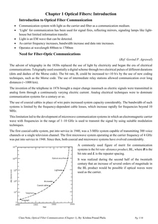
  • 1. Class Note, Optical Fiber Communication (Chapter 1), By: Krishna Prasad Phelu Pg. 1/18 Chapter 1 Optical Fibers: Introduction Introduction to Optical Fiber Communication  Communication system with light as the carrier and fiber as a communication medium.  ‘Light’ for communication has been used for signal fires, reflecting mirrors, signaling lamps like light- house but limited information transfer.  Light is an EM wave that can be detected.  As carrier frequency increases, bandwidth increase and data rate increases.  Operates at wavelength 800nm to 1700nm Need for Fiber-Optic Communications (Ref: Govind P. Agrawal) The advent of telegraphy in the 1830s replaced the use of light by electricity and began the era of electrical communications. Telegraphy used essentially a digital scheme through two electrical pulses of different durations (dots and dashes of the Morse code). The bit rate, B, could be increased to∼10 b/s by the use of new coding techniques, such as the Morse code. The use of intermediate relay stations allowed communication over long distances (∼1000 km). The invention of the telephone in 1876 brought a major change inasmuch as electric signals were transmitted in analog form through a continuously varying electric current. Analog electrical techniques were to dominate communication systems for a century or so. The use of coaxial cables in place of wire pairs increased system capacity considerably. The bandwidth of such systems is limited by the frequency-dependent cable losses, which increase rapidly for frequencies beyond 10 MHz. This limitation led to the development of microwave communication systems in which an electromagnetic carrier wave with frequencies in the range of 1–10 GHz is used to transmit the signal by using suitable modulation techniques. The first coaxial-cable system, put into service in 1940, was a 3-MHz system capable of transmitting 300 voice channels or a single television channel. The first microwave system operating at the carrier frequency of 4 GHz was put into service in 1948. Since then, both coaxial and microwave systems have evolved considerably. A commonly used figure of merit for communication systems is the bit rate–distance product, BL, where B is the bit rate and L is the repeater spacing. It was realized during the second half of the twentieth century that an increase of several orders of magnitude in the BL product would be possible if optical waves were used as the carrier.
  • 2. Class Note, Optical Fiber Communication (Chapter 1), By: Krishna Prasad Phelu Pg. 2/18 However, neither a coherent optical source nor a suitable transmission medium was available during the 1950s.  The invention of the laser and its demonstration in 1960 solved the first problem.  It was suggested in 1966 that optical fibers might be the best choice, as they are capable of guiding the light in a manner similar to the guiding of electrons in copper wires. The main problem was the high losses of optical fibers - fibers available during the 1960s had losses in excess of 1000 dB/km. A breakthrough occurred in 1970 when fiber losses could be reduced to below 20 dB/km in the wavelength region near 1µm. The commercial deployment of lightwave systems followed the research and development phase closely. As a result, the bit rate–distance product of modern lightwave systems can exceed by a factor of 107 compared with the first-generation lightwave systems. Optical Fiber Communication system block diagram (Ref: John M. Senior) An optical fiber communication system is similar in basic concept to general communication system. The function of communication system is to convey the signal from the information source over the transmission medium to the destination. The communication system therefore consists of a transmitter or modulator linked to the information source, the transmission medium, and a receiver or demodulator at the destination point. In electrical communications the information source provides an electrical signal, usually derived from a message signal which is not electrical (e.g. sound), to a transmitter comprising electrical and electronic components which converts the signal into a suitable form for propagation over the transmission medium. This is often achieved by modulating a carrier, which, may be an electromagnetic wave. The transmission medium can consist of a pair of wires, a coaxial cable or a radio link through free space down which the signal is transmitted to the receiver, where it is transformed into the original electrical information signal (demodulated) before being passed to the destination. For optical fiber communications the system, the information source provides signal to a transmitter comprising an electrical stage which drives an optical source to give modulation of the lightwave carrier. The optical source which provides the electrical–optical conversion may be either a semiconductor laser or light-emitting diode
  • 3. Class Note, Optical Fiber Communication (Chapter 1), By: Krishna Prasad Phelu Pg. 3/18 (LED). The transmission medium consists of an optical fiber cable and the receiver consists of an optical detector which drives a further electrical stage and hence provides demodulation of the optical carrier. Photodiodes (p–n, p–i–n or avalanche) and, in some instances, phototransistors and photoconductors are utilized for the detection of the optical signal and the optical–electrical conversion. Thus there is a requirement for electrical interfacing at either end of the optical link and at present the signal processing is usually performed electrically. But, significant developments have taken place in devices for optical signal processing which are starting to alter this situation. The optical carrier may be modulated using either an analog or digital information signal. Analog modulation involves the variation of the light emitted from the optical source in a continuous manner. With digital modulation, however, discrete changes in the light intensity are obtained (i.e. on–off pulses). Although often simpler to implement, analog modulation with an optical fiber communication system is less efficient, requiring a far higher signal-to-noise ratio at the receiver than digital modulation. Also, the linearity needed for analog modulation is not always provided by semiconductor optical sources, especially at high modulation frequencies. For these reasons, analog optical fiber communication links are generally limited to shorter distances and lower bandwidth operation than digital links. Following figure shows a block schematic of a typical digital optical fiber link: Initially, the input digital signal from the information source is suitably encoded for optical transmission. The laser drive circuit directly modulates the intensity of the semiconductor laser with the encoded digital signal. Hence a digital optical signal is launched into the optical fiber cable. The avalanche photodiode (APD) detector is followed by a front-end amplifier and equalizer or filter to provide gain as well as linear signal processing and noise bandwidth reduction. Finally, the signal obtained is decoded to give the original digital information. Repeaters can be used for long distance digital communication system. They convert weak and distorted optical signals to electrical signals and then regenerate original digital pulse train for further transmission. In long systems numerous amplifiers and repeaters may be used. Advantages of optical fiber communication (Ref: John M. Senior) Communication using an optical carrier wave guided along a glass fiber has a number of extremely attractive features: a) Enormous potential bandwidth. The optical carrier frequency in the range 1013 to 1016 Hz yields a far greater potential transmission bandwidth than metallic cable systems (i.e. coaxial cable bandwidth typically around 20 MHz over distances up to a maximum of 10 km) or even millimeter wave radio systems (i.e. systems currently operating with modulation bandwidths of 700 MHz over a few hundreds of meters).
  • 4. Class Note, Optical Fiber Communication (Chapter 1), By: Krishna Prasad Phelu Pg. 4/18 Indeed, by the year 2000 the typical bandwidth - length product for an optical fiber link incorporating fiber amplifiers was 5000 GHz km in comparison with the typical bandwidth–length product for coaxial cable of around 100 MHz km. Hence optical fiber was already demonstrating a factor of 50000 bandwidth – length improvement over coaxial cable while also providing this superior information-carrying capacity over much longer transmission distances. Use of wavelength division multiplexed (WDM) operation can further enhanced bandwidth utilization of an optical fiber. b) Small size and weight Optical fibers have very small diameters which are often no greater than the diameter of a human hair. Hence, even when such fibers are covered with protective coatings they are far smaller and much lighter than corresponding copper cables. Hence optical fibers are portable, easy for ducting and installation as well as suitable for an expansion of signal transmission within aircraft, satellites and even ships. c) Electrical isolation Optical fibers which are fabricated from glass, or sometimes a plastic polymer, are electrical insulators and therefore there is no arcing, spark or short circuit hazard. d) Immunity to interference and crosstalk Optical fibers form a dielectric waveguide and are therefore free from electromagnetic interference (EMI), radio- frequency interference (RFI), or switching transients giving electromagnetic pulses (EMPs). Hence  The operation of an optical fiber communication system is unaffected by transmission through an electrically noisy environment  The fiber cable requires no shielding from EMI.  The fiber cable is also not susceptible to lightning strikes if used overhead rather than underground.  No optical interference between fibers and hence, unlike communication using electrical conductors, crosstalk is negligible, even when many fibers are cabled together. e) Increased Signal security The light from optical fibers does not radiate significantly and therefore they provide a high degree of signal security. Unlike the situation with copper cables, a transmitted optical signal cannot be obtained from a fiber in a noninvasive manner (i.e. without drawing optical power from the fiber). If the cable is tapped, it’s very easy to monitor because the cable leaks light, causing the entire system to fail. Therefore, in theory, any attempt to acquire a message signal transmitted optically may be detected. This feature is obviously attractive for military, banking and general data transmission (i.e. computer network) applications. f) Low transmission loss Optical fiber cables which exhibit very low attenuation or transmission loss in comparison with the copper conductors. Fibers have been fabricated with losses as low as 0.15 dB km−1 . It facilitates the implementation of communication links with extremely wide optical repeater or amplifier spacings, thus reducing both system cost and complexity. g) System reliability and ease of maintenance Due to low-loss property of optical fiber cables, requirement for intermediate repeaters reduces. Hence with fewer optical repeaters or amplifiers, system reliability is generally enhanced in comparison with conventional electrical conductor systems.
  • 5. Class Note, Optical Fiber Communication (Chapter 1), By: Krishna Prasad Phelu Pg. 5/18 h) Potential low cost The glass which generally provides the optical fiber transmission medium is made from sand – not a scarce resource. So, in comparison with copper conductors, optical fibers offer the potential for low-cost line communication for bulk purchases. Overall system costs when utilizing optical fiber communication on long- haul links are substantially less than those for equivalent electrical line systems because of the low-loss and wideband properties of the optical transmission medium. Although optical fiber transmission medium has become competitive with copper wires (i.e. twisted pairs), it has not yet been achieved in all the other component areas associated with optical fiber communications. For example, the costs of high-performance semiconductor lasers and detector photodiodes are still relatively high, as well as some of those concerned with the connection technology (demountable connectors, couplers, etc.). Basic laws and definitions (Ref: G. Keiser and John M. Senior) Refractive index To consider the propagation of light within an optical fiber utilizing the ray theory model it is necessary to take account of the refractive index of the dielectric medium. The refractive index of a medium is defined as the ratio of the velocity of light in a vacuum to the velocity of light in the medium. A ray of light travels more slowly in an optically dense medium than in one that is less dense, and the refractive index gives a measure of this effect. In free space a light wave travels at a speed c = 3 x 10⁸ m/s. Upon entering a dielectric or non-conducting medium the wave now travels at a speed v, which is characteristic of the material and is less than c. The ratio of speed of c to v is the index of refraction n of the material, Typical values of n are 1.00 for air, 1.33 for water, 1.50 for glass, and 2.42 for diamond. Reflection and Refraction
  • 6. Class Note, Optical Fiber Communication (Chapter 1), By: Krishna Prasad Phelu Pg. 6/18 When light traveling in a certain medium is reflected off an optically denser material (one with a higher refractive index), the process is referred to as external reflection. Conversely, the reflection of light off of less optically dense material (such as light traveling in glass being reflected at a glass-to-air interface) is called internal reflection. Total internal reflection Consider a ray approaching the interface is propagating in a dielectric of refractive index n1 and is at an angle ϕ1 to the normal at the surface of the interface. If the dielectric on the other side of the interface has a refractive index n2 which is less than n1, then the refraction is such that the ray path in this lower index medium is at an angle ϕ2 to the normal, where ϕ2 is greater than ϕ1. From Snell’s law of refraction: Or:
  • 7. Class Note, Optical Fiber Communication (Chapter 1), By: Krishna Prasad Phelu Pg. 7/18 As n1 is greater than n2, the angle of refraction is always greater than the angle of incidence. As angle of incidence becomes greater, the angle of refraction also goes on increasing. When the angle of refraction is 90° and the refracted ray emerges parallel to the interface between the dielectrics, the angle of incidence must be less than 90°. This is the limiting case of refraction and the angle of incidence is now known as the critical angle ϕc. The value of the critical angle is given by1 : At angles of incidence greater than the critical angle on refraction is possible and the light is reflected back into the originating dielectric medium (total internal reflection) with high efficiency (around 99.9%). Hence, total internal reflection occurs at the interface between two dielectrics of differing refractive indices when light is incident on the dielectric of lower index from the dielectric of higher index, and the angle of incidence of the ray exceeds the critical value. This is the mechanism by which light propagate down an optical fiber with low loss. Transmission of a light ray in an optical fiber via a series of total internal reflections at the interface of the silica core and the slightly lower refractive index silica cladding is shown in figure below. The ray has an angle of incidence ϕ at the interface which is greater than the critical angle and is reflected at the same angle to the normal. 1 Sin(900 ) = 1
  • 8. Class Note, Optical Fiber Communication (Chapter 1), By: Krishna Prasad Phelu Pg. 8/18 The light ray shown in above Figure is known as a Meridional ray as it passes through the axis of the fiber core. This type of ray is the simplest to describe and is generally used when illustrating the fundamental transmission properties of optical fibers. Another possible ray in optical fiber is Skew ray. A skew ray is a ray that travels in a non-planar zig-zag helical path which neither pass through the fiber axis nor parallel to the fiber axis. Any discontinuities or imperfections at the core–cladding interface would probably result in refraction rather than total internal reflection, with the subsequent loss of the light ray into the cladding. Acceptance angle Not all rays entering the fiber core will continue to be propagated down its length. Only rays with a sufficiently shallow grazing angle (i.e. with an angle to the normal greater than ϕc) at the core–cladding interface are transmitted by total internal reflection. The geometry concerned with launching a light ray into an optical fiber is shown in Figure below, which illustrates a meridional ray A at the critical angle ϕc within the fiber at the core– cladding interface. Ray A enters the fiber core at an angle θa to the fiber axis and is refracted at the air–core interface before transmission to the core–cladding interface at the critical angle. Any rays (B) which are incident into the fiber core at an angle greater than θa will be transmitted to the core– cladding interface at an angle less than ϕc, and will not be totally internally reflected rather than it is refracted into the cladding and eventually lost by radiation. Thus for rays to be transmitted by total internal reflection within the fiber core they must be incident on the fiber core within an acceptance cone defined by the conical half angle θa. Hence θa is the maximum angle to the axis
  • 9. Class Note, Optical Fiber Communication (Chapter 1), By: Krishna Prasad Phelu Pg. 9/18 at which light may enter the fiber in order to be propagated, and is often referred to as the acceptance angle for the fiber. Numerical aperture We can to continue the ray theory analysis to obtain a relationship between the acceptance angle and the refractive indices of the three media involved, namely the core, cladding and air. This leads to the definition of a more generally used term, the numerical aperture of the fiber. Consider light ray incident on the fiber core at an angle θ1 to the fiber axis which is less than the acceptance angle for the fiber θa. The ray enters the fiber from a medium (air) of refractive index n0, and the fiber core has a refractive index n1, which is slightly greater than the cladding refractive index n2. Assuming the entrance face at the fiber core to be normal to the axis. Consider the refraction at the air–core interface and using Snell’s law given by: Considering the right-angled triangle ABC in above figure: where ϕ is greater than the critical angle at the core–cladding interface. Substituing θ2 in Snell’s law equation2 , Using the trigonometrical relationship sin2 X+cos2 X=1, When the limiting case for total internal reflection is considered, ϕ becomes equal to the critical angle, ϕc, for the core–cladding interface which is sinϕc=n2/n1. Also in this limiting case θ1 becomes the acceptance angle for the fiber θa. With these substitutions, Numerical Aperture (NA) is defined as: 2 sin(pi/2 - X) = cosX
  • 10. Class Note, Optical Fiber Communication (Chapter 1), By: Krishna Prasad Phelu Pg. 10/18 Since the NA is often used with the fiber in air where n0 is unity, it is simply equal to sinθa. It may also be noted that incident meridional rays over the range 0 ≤θ1≤θa will be propagated within the fiber. Acceptance angle in air for the fiber can be calculated as, The NA may also be given in terms of the relative refractive index difference Δ between the core and the cladding which is defined as: Taking under root, Hence NA we can also be write as: for Δ<<1, The numerical aperture is a very useful measure of the light-collecting ability of a fiber. They are independent of the fiber core diameter and will hold for diameters as small as 8μm. However, for smaller diameters they break down as the geometric optics approach is invalid. This is because the ray theory model is only a partial description of the character of light. Question 1: A silica optical fiber with a core diameter large enough to be considered by ray theory analysis has a core refractive index of 1.50 and a cladding refractive index of 1.47. Determine: (a) the critical angle at the core–cladding interface; (b) the NA for the fiber; (c) the acceptance angle in air for the fiber. Solution: a) The critical angle ϕc at the core–cladding interface is given by, b) The NA is: c) The acceptance angle in air θa is given by:
  • 11. Class Note, Optical Fiber Communication (Chapter 1), By: Krishna Prasad Phelu Pg. 11/18 Question 1: A typical relative refractive index difference for an optical fiber designed for long distance transmission is 1%. Estimate the NA in air for the fiber when the core index is 1.46. Further, calculate the critical angle at the core–cladding interface within the fiber. It may be assumed that the concepts of geometric optics hold for the fiber. Solution: Relative refractive index difference, Δ=0.01 So, the NA is The relative refractive index difference Δ gives: Hence, The critical angle at the core–cladding interface is: Numerical aperture for Skew rays Skey ray is transmitted without passing through the fiber axis and following a helical path through the fiber. The helical path traced through the fiber gives a change in direction of 2γ at each reflection, where γ is the angle between the projection of the ray in two dimensions and the radius of the fiber core at the point of reflection. In order to calculate the acceptance angle for a skew ray it is necessary to define the direction of the ray in two perpendicular planes. The geometry of the situation is illustrated in Figure below where a skew ray is shown incident on the fiber core at the point A, at an angle θs to the normal at the fiber end face. The ray is refracted at the air–core interface before traveling to the point B in the same plane. The angles of incidence and reflection at the point B are ϕ, which is greater than the critical angle for the core–cladding interface.
  • 12. Class Note, Optical Fiber Communication (Chapter 1), By: Krishna Prasad Phelu Pg. 12/18 When considering the ray between A and B it is necessary to resolve the direction of the ray path AB to the core radius at the point B. As the incident and reflected rays at the point B are in the same plane, this is simply cosϕ. To find another resolution, γ is the angle between the core radius (BR) and the projection of the ray AB onto a plane BRT normal to the core axis (BT). And θ is the angle between the ray and a line AT drawn parallel to the core axis. Thus to resolve the ray path AB relative to the radius BR requires multiplication by cos γ and sin θ. Both of these resolution are that of the same ray AB. So, they should be equal Using the trigonometrical relationship, sin2 X+cos2 X=1. If the limiting case for total internal reflection is now considered, then ϕ becomes equal to the critical angle ϕc for the core–cladding interface and sinϕc = n2/n1. So above equation can be written as, Above equation is shown as inequality because here ϕ is specified for limiting case of critical angle ϕc but θ is not specified for limiting case. Furthermore, using Snell’s law at the point A, where θa represents the maximum input axial angle for meridional rays and θ is the internal axial angle. Substituting for sin θ from above equation gives: where θas now represents the maximum input angle or acceptance angle for skew rays. It may be noted that the inequality shown previously is no longer necessary as all the terms are specified for the limiting case. Thus the acceptance conditions for skew rays are: and in the case of the fiber in air (n0=1):
  • 13. Class Note, Optical Fiber Communication (Chapter 1), By: Krishna Prasad Phelu Pg. 13/18 Comparisons between meridional ray and skew ray Comparing NA for meridional rays and skew rays, it may be noted that skew rays are accepted at larger axial angles in a given fiber than meridional rays, depending upon the value of cos γ. For cos γ is equal to unity and θas = θa which represents meridional rays. Thus θa is the maximum conical half angle for the acceptance of meridional rays and it defines the minimum input angle for skew rays. Skew rays tend to propagate only in the annular region near the outer surface of the core, and do not fully utilize the core as a transmission medium. Skew rays increase the light-gathering capacity of the fiber. This increased light-gathering ability may be significant for large NA fibers, but for most communication design purposes the meridional rays are considered adequate. Question 3: An optical fiber in air has an NA of 0.4. Compare the acceptance angle for meridional rays with that for skew rays which change direction by 100° at each reflection. Solution: The acceptance angle for meridional rays with n0=1 is: The skew rays change direction by 100° at each reflection, therefore γ=50°. Hence the acceptance angle for skew rays is: Optical Fiber (Ref: G. Keiser) Structure of Optical Fiber Optical fiber acts as a waveguide or light pipe. It is a single solid dielectric cylinder of radius ‘a’ and index of refraction n1 as shown in figure below. This cylinder is known as the core of fiber. The core is surrounded by solid dielectric cladding having a refractive index n2 that is less than n1. In low-loss and medium-loss fiber core is made from glass and cladding is made from either glass or plastic. But high loss fiber is made from plastic-core and plastic cladding. In principle cladding is not necessary for light to propagate along the core of the fiber, it serves several purposes:  Reduces scattering loss of light resulting from dielectric discontinuities from the core into the surrounding air  Adds mechanical strength  Protects the core from absorbing surface contaminants. Cladding is further encapsulated in an elastic plastic material called buffer coating. It adds further strength to the fiber and mechanically isolates or buffers the fibers from small geometrical irregularities, distortions or
  • 14. Class Note, Optical Fiber Communication (Chapter 1), By: Krishna Prasad Phelu Pg. 14/18 roughnesses of adjacent surfaces. These perturbations could otherwise cause scattering losses induced by random microscopic bends on installation. Types of Optical fiber On the basis of core-cladding refractive index profile a) Step Index b) Graded Index On the basis of number of modes supported a) Single mode b) Multi Mode Step Index Fiber The optical fiber with a core of constant refractive index n1 and a cladding of a slightly lower refractive index n2 is known as step index fiber. This is because the refractive index profile for this type of fiber makes a step change at the core–cladding interface. The refractive index profile may be defined as: Graded index fibers Graded index fibers do not have a constant refractive index in the core but a decreasing core index n(r) with radial distance from a maximum value of n1 at the axis to a constant minimum value n2 beyond the core radius ‘a’ in the cladding. This index variation may be represented as: Where,
  • 15. Class Note, Optical Fiber Communication (Chapter 1), By: Krishna Prasad Phelu Pg. 15/18 Δ= (n1-n2)/n1, is the relative refractive index difference and α is the profile parameter which gives the characteristic refractive index profile of the fiber core Refractive index profile of the fiber core can be expressed as a variation of α  When α=∞ it represents the step index profile  When α=2 it represents a parabolic profile  When α=1 it represents a triangular profile Single Mode Fiber (SMF) Single mode fiber sustains only one fundamental mode of light propagation. Single mode the fiber is designed to allow propagation of only one mode, while all other modes are attenuated by leakage or absorption. Single mode fiber has small core size and the index of refraction between the core and the cladding changes less than it does for multimode fibers. Widely deployed single-mode fibers employ a step index profile design. Advantages of single mode fiber  They exhibit the greatest transmission bandwidths and the lowest losses of the fiber transmission media.  They have a superior transmission quality over other fiber types because of the absence of modal noise.  Suitable for long distance transmission. Multimode Fiber Multimode fiber has a larger core diameter than that of single mode fiber, which is large enough to allow the propagation of many modes within the fiber core simultaneously. When one pulse of signal is generated into multimode fiber the multiple modes enter the fiber core from different angles and each modes propagates at different speeds and causes pulse broadening (modal dispersion). Generally it is used for short and medium distance. Multimode step index fiber has a core diameter of around 50μm or greater. It allows many different possible ray paths through the fiber. In multimode step index fiber considerable dispersion may occur due to the differing
  • 16. Class Note, Optical Fiber Communication (Chapter 1), By: Krishna Prasad Phelu Pg. 16/18 group velocities of the propagating modes. This in turn restricts the maximum bandwidth attainable with multimode step index fibers, especially when compared with single-mode fibers. Multimode Graded-Index fiber contains a core in which the refractive index diminishes gradually from the center axis out toward the cladding. The meridional rays appear to follow curved paths through the graded index multimode fiber core rather than zigzagging off the cladding. Using the concepts of geometric optics, the gradual decrease in refractive index from the center of the core creates many refractions of the rays as they are effectively incident on a large number of high to low index interfaces. As a result ray is gradually curved and the ray travels back towards the core axis, again being continuously refracted. Multimode graded index fibers exhibit far less intermodal dispersion than multimode step index fibers due to their refractive index profile. The rays traveling close to the fiber axis have shorter paths when compared with rays which travel into the outer regions of the core. However, the near axial rays are transmitted through a region of higher refractive index and therefore travel with a lower velocity than the more extreme rays. This compensates for the shorter path lengths and reduces dispersion in the fiber. Hence, multimode graded index fibers with parabolic or near-parabolic index profile cores have transmission bandwidths which may be orders of magnitude greater than multimode step index fiber bandwidths. Following table shows the different types of fibers and their dispersive characteristics. Advantages of Multimode Fiber  The larger core radii of multimode fibers make it easier to launch optical power into the fiber  Lower tolerance required in fiber joints.  Light can be launched into a multimode fiber using a light emitting diode (LED) source, whereas single- mode fibers must generally be exited with laser diodes. Although LEDs have less optical output power than laser diodes they are easier to make, are less expensive, require less complex circuitry, and have longer lifetimes than laser, thus making them more desirable in many applications.
  • 17. Class Note, Optical Fiber Communication (Chapter 1), By: Krishna Prasad Phelu Pg. 17/18 Disadvantage of Multimode Fiber  Multimode fiber suffer from intermodal dispersion where as in single mode fibers intermodal dispersion effects are not present. When an optical pulse is launched into a fiber, the optical power in the pulse is distributed over all of the modes of the fiber. Each modes that can propagate in a multimode fiber travels at a slightly different velocity. This means that the modes in a given optical pulse arrive at the fiber end at slightly different times, thus causing the pulse to spread out in time as it travels along the fiber. o This effect can be reduced by using a graded index profile in the fiber core. Application of OFC: Fiber optics has tremendous application in every part of life and several such applications have already been implemented in practice to varying degrees. Some of detailed applications are as follows: 1. Telecommunication/Telephone applications:- The various applications of fiber optics in the telecommunication area in general could be in voice telephone, video phones, various new services, messages services and data networks all transmitted over the common carrier link. 2. Military application:- These include communication, command and control links on ships and aircraft, data links for satellite earth stations and under sea system for which EMI effect, weight and size, signal leakage and attenuation plays a major role. OFC systems meet this requirement. 3. Space application:- Optical fibers offer the following significant advantages for space environment ;namely high bandwidth( greater than 1 Ghz as compared to 1 Mhz for twisted pair), noise immunity, inherent radiation, reduce weight (90% weight savings over conventional wire system), low bit error rate, size and volume reduction, EMI immunity and lower cost. 4. Sensor application:- A fiber optic sensor consists of a length of a fiber that modulates the light passing though it when exposed to the changing environment one wants to sense. The physical effects exposed to the environment lead to changes in frequency, intensity and polarization of light and thus cause variation in the resultant optical signal. 5. Under sea transmission cables:- Coaxial under sea cable systems have been used as one of the major transmission systems in international telecommunication networks over the past 25 years. But this system has nearly reached a limit in its ability to increase the capacities. Therefore optical fiber under sea cable system are considered to be very promising technology to over come these barriers. 6. Broad band applications: Application that are primilarly broadband services include broadcast tv, cable tv (CTV, community antenna television), remote monitory, and surveillance system.
  • 18. Class Note, Optical Fiber Communication (Chapter 1), By: Krishna Prasad Phelu Pg. 18/18 7. Computer application:- Fiber system are particularly suited for transmission of digital data, such as that generated by the computers. Interconnections can be made between CPU and memories, CPU and peripherals and between CPUs. 8. OFC for electric power companies:- Electric power companies are progressively installing the OFC system for power system protections, supervision and control, measurements etc. 9. Miscellaneous:- These include biomedical applications. General home appliances application. Small office building and so on.