Takex PB-200EX Instruction Manual
•
0 gefällt mir•78 views

Buy the Takex PB-200EX at JMAC Supply. https://www.jmac.com/Takex_PB_200EX_p/takex-pb200ex.htm?=slideshare

Empfohlen
Empfohlen
Weitere ähnliche Inhalte
Was ist angesagt?
Was ist angesagt? (13)
Ähnlich wie Takex PB-200EX Instruction Manual
Ähnlich wie Takex PB-200EX Instruction Manual (20)
Mehr von JMAC Supply
Mehr von JMAC Supply (20)
Kürzlich hochgeladen
Kürzlich hochgeladen (20)
Takex PB-200EX Instruction Manual
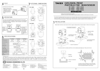
- 1. L imited Warranty : T AK E X products are warranted to be free from defects in material and workmanship for 12 months from original date of shipment. Our warranty does not cover damageor failure caused by Acts of God (including inductive surge by lightning), abuse, misuse, abnormal usage, faulty installation, improper maintenance or any repairs other than those provided by T AK E X. All implied warranties with respect to T AK E X, including implied warranties for merchantability and implied warranties for fitness, are limited in duration to 12 months from original date of shipment. During the Warranty Period, T AK E X will repair or replace, at its sole option, free of charge, any defective parts returned prepaid. Please provide the model number of the products, original date of shipment and nature of difficulty being experienced. There will be charges rendered for product repairs made after our Warranty period has expired. In Japan Takex America Inc. Unit 16/35 Garden R oad, Clayton, 3168 Victoria, Australia Tel : 03-9546-0533 Fax : 03-9547-9450 Takex America Inc. Brisbane office : 1/50 Logan R oad, Woolloongabba Queensland 4102, Australia Tel : 07-3891-3344 Fax : 07-3891-3355 Takenaka E ngineering Co., Ltd. 83-1, Gojo-sotokan, Higashino, Yamashina-ku, Kyoto 607-8156, Japan Tel : 81-75-501-6651 Fax : 81-75-593-3816 http : // www. takex-eng. co. jp Takex America Inc. 3350 Montgomery Drive , S anta Clara, CA 95054, U.S .A. Tel : 408-747-0100 Fax : 408-734-1100 http : // www. takex. com Takex E urope Ltd. Takex House, Aviary Court, Wade R oad, Basingstoke, Hampshire. R G24 8PE , U.K. Tel : (+44) 01256-475555 Fax : (+44) 01256-466268 http : // www. takexeurope. com In the U.S . In the U.K.In Australia PB-100EX : 330ft (100m) PB-200EX : 660ft (200m) PB-400EX : 1320ft (400m) T hank you for purchasing this product. R ead this instruction manual before using the product to make sure that you use it correctly. EXPLOSION-PROOF PHOTOELECTRIC BEAM SENSOR Instruction Manual 4 6 N o.04-186 1110 E XTE R NAL DIME NS IONS Unit : mm 7 T he T AK E X E xplosion-proof Sensor consists of a transmitter which emits the infrared pulsed beam and a receiver which receives the beam. T he units are manufactured in accordance with T echnical R ecommendations by Ministry of L abour, T he R eserch I nstitute of I ndustrial Safety J apan. Please read this manual carefully for correct and effective use. INS TALLATION 1 T o be constructed in accordance with the rule for explosion-proof apparatus. Please refer I tem 2) . T o protect around a building as illustrated adove, install the transmitters and the recievers so as to cross infrared pulse beames at each corner. Gravel Concrete F oundation Welding Steel Pipe Mount both transmitter and receiver on their respective tables which are fixed at 80cm to 100cm from the ground. PB-100EX PB-200EX PB-400EX T he L E Ds in the windows on the back of transmitter and receiver will light when power is supplied. T hen the units are in the protected condition the receiver L E D goes out, when the beam is interrupted, the receiver L E D lights. OPE R ATION 5 Hole for Conduit (PF-lT/1) Hole for Conduit (PF-lT/1) Hole for Conduit (PF-lT/1) 1 4-M12 4-M12 4-M12 Hole for M16 Bolt Hole for M16 Bolt Hole for M16 Bolt T R . R E . T R . T R . T R . T R .R E . R E . R E . R E . B uilding Window T ransmitter R eciever T ransmitter L E D R eciever L E D T ransmitter & R eceiver H ole for Conduit (PF -lT /1) F ixed Mounting T able (N ot included) J unction (Wiring) B ox (N ot included)Steel Pipe (N ot included) Concrete F oundation Conduit Pipe (N ot included) TE S T 4 Sensitivity test sheet (include) Apply the sheet on the reciever lens. Sensitivity is good when reciever L E D does not light up. (Details show on the sheet) Make sure that the L E D(green). lights up with power ON . With power ON , the reciever will receive an infrared pulesed beam and then the L E D(red) will light off, if the alignment is correct. S PE CIFICATIONS Model Max.Arrival distance S upply voltage Alarm signal R esponse time 800m(2640ft) 100m(330ft) or less ( ×8 ) 50 to 100msec R elay output S .P.S .T(N/C) R eset time : Approx 1sec. Contact rating : 100V ・ 0.5A ・ Max 10VA AC 100V 50/60Hz Power consumption Transmitter : 2.5VA R eceiver : 3VA PB-100E X Infrared rays Pulsed beam by infrared LE D Wave length :9400Å Double modulated frequency 500Hz to 20KHz PB-200E X PB-400E X Protection distance 200m(660ft) or less 400m(1320ft) or less 1600m(5280ft) 3200m(10560ft) Ambient temperature range -35℃ to +60℃(-30F to +140F) C lass I & Ⅱ hazardous location Transmitter : 10kg Transmitter : 12kg R eceiver : 10kg R eceiver : 12kg E poxy resin baked coating stainless steel plate Mounting position Weight Appearance T ransmitter R eciever
- 2. WIR ING 2 2-l Wire Materials I . E . a) 600V grade polyvinyl chloride insulated wires (I V ) ・・・J I S C 3307 b) 600V grade heat-resistant polyvinyl chloride insulated wires(H I V ) ・・・J I S C 3317 c) 600V grade aluminum conductor polyvinyl :chloride insulated wires(AI -I V ) ・・・J I S C 3372 d) 600V grade natural rubber insulated wires(SB R ) ・・・J I S C 3304 e) 600V grade silicon 'rubber insulated glass fiber braided wires (K GB ) ・・・J I S C 3323 f) 600V grade polyethylene insulated wires (I E ) ・・・J I S C 3326 g) Other wires similar in position to the above. (2) Conduit (3) Accessories for conduit (I ron and steel pipe fittings) (1) Screw threads (1) U se insulated wires enclosed is rubber, vinyl, polyethylene or fluoro-carbon resin. 2- 2 Conduit Arrangement (2) F lexible fittings (couplings) (3) Sealing a) On one side of the conduit which passes through the wall between a class I hazardous location and the other except on the conduit between the sealing fittings and wall. 2-3 Drip-pcoof When it is apparent that water may collect in conduit, boxes and sealing fittings, prevent water from' staying in by providing drainage. 2-4 Wiring (1) Detach the the back cover of transmitter and receiver with the hexagon wrench provided. -E xample - (1) L ook through the view finder on transmitter and receiver. Adjust with the mounting hole and the vertical adjustment nut until the opposite unit is centered in the finder. *H orizontal Adjustment Accessible through the mounting hole. Adjustable range is 10°(±5°) . *V ertical Adjustment U se the vertical adjustment screw on the back. Adjustable range is 8°. U se rigid steel conduit (J I S C 8305) . U se junction boxes, couplings, sealing fittings and flexible fitting shaving pressure and explosion proof construction. U se lock nuts for rigid metal conduit. Conduit is connected to fittings or terminal boxes with parallel pipe threads . T ighten with lock nuts after threading 5 threads or mere. U se flexible fittings or couplings where flexibility is required. T he inner radius when bending a curve must be 5 times or more the outer diameter of fitting tube. Do not use a wrench on the flexible fittings. Mount the sealing fittings on the conduit as described below. F ill the inside of the fittings with compounds to shut off the conduit pipe. b) I f you use J I S N o.54 or. bigger number conduit pipe, fill the fittings with compounds close to 'and within 45cm from the terminal box or the like which includes wire junction in. (T he closer, the better. ) c) Whithin 45m from the box and as close to it as possible on the conduit which is feeding in or out of the terminal box or junction box in a distributor panel. T erminal box coverH exagon B olt (T ypical) (3) After wiring, re-attach the terminal cover. (4) R efer to E xplosion-proof standards for other wiring work. (2) T he following figures show terminal arrangement. Connect 100V power source with 100V , terminals on transmitter and receiver. Connect the wires from control panel with the contact terminals on receiver. ALIGNME NT 3 10° Mounting H ole 8° V ertical adjustment nut Alignment V iew F inder Alignment V iew F inder V ertical adjustment nut (2) PB -400E X(1) PB -100E X, PB -200E X 32 T ransmitter R eceiver Ground Power AC100V T o Control Panel Alarm signal Ground Power AC100V AC100V ALARMAC100V H azardous area N on-hazardous area R igid steel conduct Pressure & explosion proof work J unction box R ecieverT ransmitter Control panel