Rifle Shooting Target Detection
•
0 likes•45 views

https://irjet.net/archives/V4/i2/IRJET-V4I2141.pdf

Recommended
Recommended
More Related Content
What's hot
What's hot (20)
Similar to Rifle Shooting Target Detection
Similar to Rifle Shooting Target Detection (20)
More from IRJET Journal
More from IRJET Journal (20)
Recently uploaded
Recently uploaded (20)
Rifle Shooting Target Detection
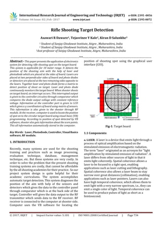
- 1. International Research Journal of Engineering and Technology (IRJET) e-ISSN: 2395 -0056 Volume: 04 Issue: 02 | Feb -2017 www.irjet.net p-ISSN: 2395-0072 © 2017, IRJET | Impact Factor value: 5.181 | ISO 9001:2008 Certified Journal | Page 734 Rifle Shooting Target Detection Asawari R Daware1, Tejasvinee Y Kale2, Kiran D Salunkhe3 1 Student of Sanjay Ghodawat Institute, Atigre , Maharashtra, India 2 Student of Sanjay Ghodawat Institute, Atigre , Maharashtra, India 3Asst professor of Sanjay Ghodawat Institute, Atigre, Maharashtra ,India ---------------------------------------------------------------------***--------------------------------------------------------------------- Abstract -This paper presentstheapplicationofelectronics system for detecting rifle shooting spot on the target board. This system is applicable for 10 meter range. It detects the position of the shooting aim with the help of laser and photodiode which are placed at the sides of board. Lasers are placed at two perpendicular sides of board and photo diodes or detectors are placed at the two remaining sides opposite to the lasers. Together laser and photo diode forms a matrix to detect position of shoot on target. Laser and photo diode continuously monitors the target board. When shooter shoots on target board, an interrupt occurs. This interrupted output is given to the controller circuitry through comparator which compares the diode output voltage with constant reference voltage. Information at the controller port is given to LCD which gives x-y coordinators of board using matrix of sensors. This information is also given to the shooter through RF module. At the receiver, computer is usedtolocatetheposition of spot on to the circular target board using visual basic (VB) programming. According to position of spot detected by VB software, shooter also gets informationaboutthescorepoints. This all information automatically stored in the computer. Key Words: Laser, Photodiode, Controller, VisualBasics software, RF module. 1. INTRODUCTION Recently, many systems are used for the shooting training and practices such as image processing, evaluation technique, database, management technique, etc. But these systems are very costly. In order to solve the problem that the present shooting training systems are costly, that cannot be affordable by the all shooting academies for their practice. So our project system design is quite helpful for their academic curriculums. The system accomplishes automatic target detection. This system diagnoses the position of the aim with help of the sensors and detectors which gives the data to the controller panel through comparator which is at the back side of the target. Controller will gives the data output to the RF transmitter which sends data to the RF receiver. RF receiver is connected to the computer at shooter side. Computer uses the VB software for locating the position of shooting spot using the graphical user interface (GUI). Fig-1: Target board 1.1 Components: a. LASER: A laser is a device that emits light through a process of optical amplification based on the stimulated emission of electromagnetic radiation. The term "laser" originated as an acronym for "light amplification by stimulated emission of radiation". A laser differs from other sources of light in that it emits light coherently. Spatial coherence allows a laser to be focused to a tight spot, enabling applications such as laser cutting and lithography. Spatial coherence also allows a laser beam to stay narrow over great distances (collimation), enabling applications such as laser pointers. Lasers can also have high temporal coherence, which allows them to emit light with a very narrow spectrum, i.e., they can emit a single color of light. Temporal coherence can be used to produce pulses of light as short as a femtosecond.
- 2. International Research Journal of Engineering and Technology (IRJET) e-ISSN: 2395 -0056 Volume: 04 Issue: 02 | Feb -2017 www.irjet.net p-ISSN: 2395-0072 © 2017, IRJET | Impact Factor value: 5.181 | ISO 9001:2008 Certified Journal | Page 735 b. PHOTODIODE: A photodiode is a semiconductor device that converts light into current. The current is generated when photons are absorbed in the photodiode.Asmallamountofcurrentisalsoproduced when no light is present. Photodiodes may contain optical filters, built-in lenses, and may have large or small surface areas. Photodiodes usuallyhaveaslower response time as their surface area increases. Photodiodes are similar to regular semiconductor diodes except that they may be either exposed (to detect vacuum UV or X-rays) or packaged with a window or optical fiber connection to allow light to reach the sensitive part of the device. Many diodes designed for use specifically as a photodiode use a PIN junction rather than a p–n junction, to increase the speed of response. A photodiodeisdesignedtooperate in reverse bias. c. RF MODULE: RF Module is a transceivers module which provides easy to use RF communication at 2.4 GHZ. It can be used to transmit and receive data at 9600 baud rates from any standardCMOS/TTLsource. It works in half duplex mode. 1.2 Transmitter Fig -1: Transmitter section. Figure 1 illustrates the transmitter section of our system. There are five components: 1) Laser; 2) Rifle gun; 3) Photodiode; 4) RF module; 5) Target box. Rifle gun is used for shooting the target. Target screen is made from a paper with circular pattern. Laser and photodiode arecontinuouslymonitorsthetargetsheet. Photodiode is reverse biased by giving supply to its negative terminal. Its positive terminal gives output to the comparator. Another input to comparator is constant reference voltage. When there is no interrupt on target board the comparator gives constant output to controller ports. When shooter shoots the target board an interrupt occurs, which changes comparator output. This causes change in voltage atparticularport pin of controllerwhichdisplaythecorresponding(X,Y) coordinators on LCD. This information is then sent to the receiver using RF module for further processing. 1.3 Receiver Fig -2: Receiver section. Figure 2 illustrates the receiver section of our system. It consists of RF receiver and computer (VB software). RF module receives data from transmitter. This data is analyzed by the VB software. In computer graphical user interface (GUI) window is created on visual basic software. GUI consists of shooter information. This information stored manually by player itself. It also consists of image of target sheet. When gun is triggered by the shooterthespotontarget board is localized onto the GUI target image. Laser
- 3. International Research Journal of Engineering and Technology (IRJET) e-ISSN: 2395 -0056 Volume: 04 Issue: 02 | Feb -2017 www.irjet.net p-ISSN: 2395-0072 © 2017, IRJET | Impact Factor value: 5.181 | ISO 9001:2008 Certified Journal | Page 736 2. SIMULATION Fig 3 shows the simulation diagram of controller. The port zero and port two of controller are connected to the detectors and port one is for LCD connection.LCD shows the information about the shooting status. As shown in simulation, when there is a trigger on detector 2, controller displays the hitting to detector 2 on LCD as well as on virtual terminal. Fig -3: Simulation of controller. 3. CONCLUSIONS This paper proposes a rifle shooting target detection shooting using electronic components for detecting shooting spot on target board. The user interface application is developed on a computer to interaction with the VB software using RF module. Hence this system is applicable for shooting academies for 10m range. In future, the application range will be extended for analyzing the performance of shooting practices using zigbee or another module. ACKNOWLEDGEMENT We take this opportunity to express ourdeepregardto our faculty members Mr. Salunkhe K. D and Dr. Mrs. S. R. Chougule for their guidance and constant encouragement. Guidance and information given by faculties helps us to complete our paper. Lastly, we thank almighty, our parents and friends for their encouragement. REFERENCES [1] etarg.net - Electronic Targets for the Rest of Us. [2] https://en.wikipedia.org/wiki/Predicted_shooting. [3] E-Targ Open Source Electronic Targets - Thesis - Matt Waterman, Donato Salazar, Dr. Abul Azad (Advisor), Tech 478 – Senior Design II. [4] ICORE History and Information. BIOGRAPHIES Asawari Ramesh Daware. Final year student of Sanjay Ghodawat Institute, Atigre. Engineering Dept of E&TC work under this project. Tejasvinee Yuvaraj Kale. Final year student of Sanjay Ghodawat Institute, Atigre. Engineering Dept of E&TC work under this project. Prof. Kiran D. Salunkhe. Assistant professor of Sanjay Ghodawat Institute, Atigre. Engineering Dept of E&TC work under this project. 2nd Author Photo 3rd Author Photo ’st Author Photo