Photoelastic Stress Analysis of Bell Crank Lever: A Review
•
0 likes•161 views

https://www.irjet.net/archives/V4/i6/IRJET-V4I6597.pdf

Recommended
More Related Content
What's hot
What's hot (20)
Similar to Photoelastic Stress Analysis of Bell Crank Lever: A Review
Similar to Photoelastic Stress Analysis of Bell Crank Lever: A Review (20)
More from IRJET Journal
More from IRJET Journal (20)
Recently uploaded
Recently uploaded (20)
Photoelastic Stress Analysis of Bell Crank Lever: A Review
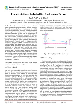
- 1. International Research Journal of Engineering and Technology (IRJET) e-ISSN: 2395 -0056 Volume: 04 Issue: 06 | June -2017 www.irjet.net p-ISSN: 2395-0072 © 2017, IRJET | Impact Factor value: 5.181 | ISO 9001:2008 Certified Journal | Page 1912 Photoelastic Stress Analysis of Bell Crank Lever: A Review Rupali Patil1, Er. N. K. Patil2 1PG Student, Dept. of Mechanical Engineering, SST’s COET, Jalgaon, Maharashtra, India 2Associate Professor, Dept. of Mechanical Engineering, SST’s COET, Jalgaon, Maharashtra, India ---------------------------------------------------------------------***--------------------------------------------------------------------- Abstract – Bell crank lever is the component which is turned about a fixed point. It is used as a machine which lifts the load by using small effort. It is mechanical device which is used to translate motion of one object to other operating at different angle. The bell crank lever is used in railway signaling, governors of hartnell type, the drive for the air pump of condensers etc. The major stresses in the bell crank lever are induced at the fulcrum i.e. bending stress and fulcrum pin is shear stress. But the maximum stress is act at fulcrum. Bell crank is the type of crank that changes motion through an angle. The angle can be varying from 0 to 360 degrees, but 90 degrees and 180 degrees are most common. Photoelasticity is an experimental technique that uses properties of light propagating through loaded or deformed components to determine and analyze the relative displacements in the material in order to establish their stress and strain fields. Photoelasticity can be applied to models in the laboratory or to prototypes in the field. Thus, it is whole field technique and it gives exact results. Photoelasticmethods are used to determine the difference between principal stress and maximum principal stress. This paper gives the review of basic concepts of Photoelastic stress analysistofindmaximum stresses in bell crank lever. Key Words: Photoelasticity, Bell crank lever, Fringes, Principle stresses, Structural analysis 1. INTRODUCTION Bell Crank Lever is important components from safety point of view as they are subjected to large amount of stresses. Hence to study the stress pattern in bell crank lever photoelasticity method can be used with analytical and numerical methods. Photoelastic technique is an experimental technique of analysis. In this virtual model of bell crank lever is prepared by taking suitable data. It is necessary to determine the stresses in various components to improve the product quality. So it is necessary to know the stress distribution in order to predict the failure of component. Bell crank lever is used to reduce a load by applying a small effort. Bell crank lever is used in the machine to lift a load by the application of a small effort. In a bell crank lever, load (W) and force (P) acts at rightanglesas shown in fig.1. The cross-section of the levercanbeobtained by considering the lever in bending. The method to find bending stress in bell crank lever i.e. numerical and experimental method is explained in next sections. After getting the output of these analyses it can be observed that results obtained are in close agreement with each other and maximum failures stress concentration occurs at maximum bending surface. Also it can be show that the results obtained by numerical and experimental methodare inclose contact with each other. Fig -1: Loading Diagram of Bell crank lever 1.1 Photoelasticity Photoelasticity is an experimental technique for stress and strain analysis which is particularly useful for members having complicated geometry, complicated loading conditions, or both. For such cases, analytical methods (that is, strictly mathematical methods) may be cumbersome or impossible, and analysisbyanexperimentalapproachmaybe more appropriate. While thevirtuesofexperimentalsolution of static, elastic, two-dimensional problems are now largely dominated by analytical methods, problems involving three- dimensional geometry, multiple-component assemblies, dynamicloading and inelastic materialbehaviourareusually more amenable to experimental analysis. The name photoelasticity indicates the nature of this experimental method: photo express the use of light rays and optical techniques, while elasticity depicts the study of stresses and deformations in elastic bodies. Through the photoelastic- coating technique, its domain has extended to inelastic bodies, too. Photoelasticanalysis is mostlyusedforproblems in whichstress or strain information isrequiredforextended regions of the structure. It provides quantitative evidence of highly stressed areas and peak stresses at surface and interior points of the structure and also it discerns areas of low stress level where structural material is utilized inefficiently. It is totally based on polarization phenomenon of light. Fig.2 shows polarization of light.
- 2. International Research Journal of Engineering and Technology (IRJET) e-ISSN: 2395 -0056 Volume: 04 Issue: 06 | June -2017 www.irjet.net p-ISSN: 2395-0072 © 2017, IRJET | Impact Factor value: 5.181 | ISO 9001:2008 Certified Journal | Page 1913 Fig -2: Polarization of Light 1.2 Polariscope A polariscope is the device used to measure photoelastic effects. When a ray of plane polarized light is passed through a photoelastic material, it gets resolved along the two principal stress directions and each of these components experiences different refractive indices. The difference in refractive indices leads to a relative phase retardation between the two component waves. The magnitude of the relative retardation is given by stress optic law:R=Ct(s1-s2) Where, R is induced retardation, C is the stress optic coefficient, t is the specimen thickness,s1isthefirstprincipal stress, ands2 is the second principal stress. Thesetwowaves are then brought together in a polariscope. Thephenomenon of optical interference takesplace and weget a fringepattern one can determine the state of stress at various points in the material. There are two main types of polariscope in use today, Plane polariscope and the Circular polariscope. In Plane polariscope the setup consists of two linear polarisers anda light source.The light source can eitheremit monochromatic or white light depending upon the experiment. Initially the light is passed through the first polarizer which converts the light into plane polarized light. Fig -3: Plane Polariscope In a circular polariscope setup, two quarter-wave plates are also added to experimental setup of the plane polariscope. Thefirstquarter-waveplateisplacedinbetween polarizer and the specimen and the second quarter wave plate is placed between the specimen and the analyser. The effect of adding the quarter-wave plates is that we get circularly polarized light. Fig -4: Circular Polariscope 2. ANALYTICAL STRESS ANALYSIS OF BELL CRANK LEVER In photoelastic method, a prototype model similar to the studied structure is made in transparent material that has photoelastic properties such as epoxy resin (mixture of Araldite CY 230 and hardener HY 951). Also circular shaped disc (calibration disc) is prepared from the same sheet. This disc is taken and subjected to compressive load in the circular polariscope as shown in figure 5.Calibration was done on the disc to find material fringe value (Fσ). Values of fringe order are noted at different loads. Using the formula Fσ =8P/πDN, material fringe values are determined. The material fringe value (Fσ) is the number of fringes produced per unit load. It is the property of the model material for a given wave length and thickness of the model. Fig -5: Fringe pattern of Calibration disc in white light source The prototype model is submitted to a representative loading of the work conditions, which take to a deformation.
- 3. International Research Journal of Engineering and Technology (IRJET) e-ISSN: 2395 -0056 Volume: 04 Issue: 06 | June -2017 www.irjet.net p-ISSN: 2395-0072 © 2017, IRJET | Impact Factor value: 5.181 | ISO 9001:2008 Certified Journal | Page 1914 Fig -6: Fringe pattern of Calibration disc in white light source The study on stress analysis of bell crank lever [3] uses photoelasticity method to find stresses in bell crank lever. It consists different shapes and volumes to find optimized size of bell crank lever. In effort arm it is observedthatthoughthe volume is reduce the maximum principal stresses at the corner of bell cranklever(Fig.6)remainsnearlyconstantand it is found to be equal to that of stresses in original model of bell crank lever. After concluding the difference between results obtained by analytically, FEM and photoelasticity reveals that they are in close harmony with each other with minimum percentage of error. The study related to photoelastic and FEM stress analysis of bell crank [4] deals with the stress analysisofbellcranklever within the angle ranges 90°to180°. The BellCrankLeverwas analyzed by the methods which are Experimental (Photoelasticity) and Numerical (Finite Element Analysis) methods, and from theobtainedresultsitisconcludedthat,at the lever section, as the load and angle between the arms increases, the maximum principal and shear stresses also increases. And the optimum angle is observed at 90°. By comparing the results experimental and analytical reveals that they are in close agreement with each other with minimum percentage of error. The stress occurred in bell crank lever with different angles is shown in following figures. Fig -7: Fringes developed in Bell crank lever of 90° Fig -8: Fringes developed in Bell crank lever of 120° Fig -9: Fringes developed in Bell crank lever of 135° Fig -10: Fringes developed in Bell crank lever of 160° 3. CONCLUSIONS After studying the papers it is found that the output of the analysis the results can be compared with numerical and FEM results, observed that results obtained are in close agreement with each other and maximum failure and stress concentration occurs at maximum bending surface. The photoelastic polariscope shows stress through fringes occurred in bell crank lever. The stress can be easily calculated by using number of fringe pattern and empirical equations. By the observation, for the complicatedproblems of arbitrary geometries the experimental method like photoelasticity is important because the results are very close to the reality.
- 4. International Research Journal of Engineering and Technology (IRJET) e-ISSN: 2395 -0056 Volume: 04 Issue: 06 | June -2017 www.irjet.net p-ISSN: 2395-0072 © 2017, IRJET | Impact Factor value: 5.181 | ISO 9001:2008 Certified Journal | Page 1915 REFERENCES [1] R. S. Khurmi, and J. K. Gupta, A Textbook of Machine Design, Eurasia Publishing House, New Delhi, 2011. [2] V. B. Bhandari, Design of machine element second edition, Tata McGraw Hill education private limited, New Delhi, 2010. [3] Mr. M. M. Dange , Prof. S. R. Zaveri and Prof.S.D.Khamankar , " Stress Analysis of Bell Crank Lever" , International Journal on Recent and Innovation Trends in Computing and Communication ISSN: 2321- 8169 Volume: 2 Issue: 8 [4] Prasanth Kumar Mallipudi, L.Dinesh, “Study on Stress Analysis of Araldite HY-951 and CY-230 Bell Crank Lever using Photoelasticity and FEM”, Journal of Information Engineering and Applications, ISSN 2224- 5782 (print) ISSN 2225-0506 (online) Vol.6, No.3, 2016 [5] Tae Hyun Baek, Myung Soo Kim and Dong Pyo Hong " Fringe Analysis for Photoelasticity Using Image Processing Techniques" International Journal of Software Engineering and Its Applications Vol.8, No.4 (2014), pp.91-102 [6] Byeong-Sam Kim, Kyoungwoo Park,“KinematicMotion Analysis and Structural Analysis of Bellcrank Structures Using FEM” , Journal of Software Engineering and Applications, Vol. 6,pp. 49-55, 2013 [7] J. W. Dally and W. F. Riley, "Experimental Stress Analysis", 2nd Ed., McGraw-Hill Inc., (1991). [8] Fang Li, "Study of Stress Measurement Using Polariscope" A thesis, Georgia Institute of Technology,August 2010