IRJET- Shock Absorber Testing using FFT Analyzer with Dewesoft
•
1 like•53 views

https://www.irjet.net/archives/V7/i1/IRJET-V7I122.pdf

Recommended
Recommended
More Related Content
What's hot
What's hot (20)
Similar to IRJET- Shock Absorber Testing using FFT Analyzer with Dewesoft
Similar to IRJET- Shock Absorber Testing using FFT Analyzer with Dewesoft (20)
More from IRJET Journal
More from IRJET Journal (20)
Recently uploaded
Recently uploaded (20)
IRJET- Shock Absorber Testing using FFT Analyzer with Dewesoft
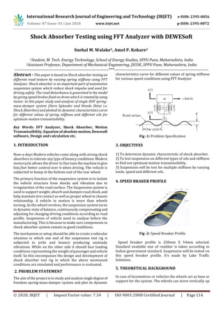
- 1. International Research Journal of Engineering and Technology (IRJET) e-ISSN: 2395-0056 Volume: 07 Issue: 01 | Jan 2020 www.irjet.net p-ISSN: 2395-0072 © 2020, IRJET | Impact Factor value: 7.34 | ISO 9001:2008 Certified Journal | Page 114 Shock Absorber Testing using FFT Analyzer with DEWESoft 1Student, M. Tech. Energy Technology, School of Energy Studies, SPPU Pune, Maharashtra, India 2Assistant Professor, Department of Mechanical Engineering, JSCOE, SPPU Pune, Maharashtra, India ---------------------------------------------------------------------***--------------------------------------------------------------------- Abstract -This paper is based on Shock absorber testingon different road texture by varying spring stiffness using FFT Analyzer. Shock absorber is an important part of automotive suspension system which reduce shock impulse and used for driving safety. The road disturbance is generated in the model by giving speed brakes fixed on drum which is rotatedby using motor. In this paper study and analysis of single DOF spring- mass-damper system (Hero Splendor and Honda Shine i.e. Shock Absorber) and plotted its dynamic characteristicscurve for different values of spring stiffness and different oils for optimum motion transmissibility. Key Words: FFT Analyzer, Shock Absorber, Motion Transmissibility, Equation ofabsolutemotion, Dewesoft software, Design and calculation etc. 1. INTRODUCTION Now-a-days Modern vehicles come along with strong shock absorbers to tolerate any type of bouncy conditions.Modern motorcycle allows the driver to fine tune themachinetogive him/her better control over it when driving. The vehicle is subjected to bump at the bottom end of the rear wheel. The primary function of the suspension system is to isolate the vehicle structure from shocks and vibration due to irregularities of the road surface. The Suspension system is used to support weight, absorb and dampen road shock,and help maintain tire contact as well as proper wheel to chassis relationship. A vehicle in motion is more than wheels turning. As the wheel revolves, the suspension system turns in dynamic state of balance, continuously compensatingand adjusting for changing driving conditions according to road profile. Suspension of vehicle need to analyse before the manufacturing. This is because to make sure components in shock absorber system remain in good conditions. The mechanism or setup should be able to create a vehicular situation in which one end of the suspension test rig is subjected to jerks and bounce producing unsteady vibrations. While on the other side it should face loading conditions representing the weight of passengerandvehicle itself. So this encompasses the design and development of shock absorber test rig in which the above mentioned conditions are simulated and performance is evaluated. 2. PROBLEM STATEMENT The aim of the project is to study andanalyze singledegreeof freedom spring-mass-damper system and plot its dynamic characteristics curve for different values of spring stiffness for various speed conditions using FFT Analyzer Fig -1: Problem Specification 3. OBJECTIVES 1) To determine dynamic characteristic of shock absorber. 2) To test suspension on different types of oils and stiffness to find out optimum motion transmissibility. 3) Suspension will be test for multiple stiffness by varying loads, speed and different oils. 4. SPEED BRAKER PROFILE Fig -2: Speed Breaker Profile Speed breaker profile is 250mm X 54mm selected. Standard available size of rumbler is taken according to Indian government standard. Suspension will be tested on this speed breaker profile. It’s made by Lake Traffic Solutions. 5. THEORETICAL BACKGROUND In case of locomotives or vehicles the wheels act as base or support for the system. The wheels can move vertically up Snehal M. Walake1, Amol P. Kokare2
- 2. International Research Journal of Engineering and Technology (IRJET) e-ISSN: 2395-0056 Volume: 07 Issue: 01 | Jan 2020 www.irjet.net p-ISSN: 2395-0072 © 2020, IRJET | Impact Factor value: 7.34 | ISO 9001:2008 Certified Journal | Page 115 and down on the road surface during the motion of the vehicle. At the same time is relative motion between the wheels and the chassis is having motion relative to the wheels and the wheels are having motion relative to the road surface. The amplitude of vibration in case of support motiondependson the speed of vehicle and nature of road surface. The vibration measuring instruments are designed on the support motion approach. Such systems are supposed to have single degree of freedom for the simplicity of mathematical expression. In a vibratory system where the support is put to excitation absolute and relative motion become important from subject point of view. 5.1 Terminology Used 1) Natural frequency (ωn) When no external force acts on the system after giving it an initial displacement, the body vibrates. These vibrations are called free vibrations and their frequency as natural frequency. It is expressed in rad/sec or Hertz. 2) Damping The external force which is provided to reduce the vibrations. 3) Critically damping co-efficient The critical damping co-efficient Cc is that value of damping coefficient c at which the frequencyoffreedampedvibration is zero and the motion is a periodic. 4) Damping co-efficient (ξ) It is defined as the ratio of damping coefficient to critical damping coefficient. Mathematically, ξ = C/Cc 5) Amplitude The maximum displacement of vibrating body from the equilibrium position. 6) Time period (tp) The time required to complete one cycle. 7) Absolute Motion Absolute motion of a mass means its motion with respect to the coordinate system attached to the earth. As shown in figure, the absolute displacement ifsupportisy=Bsinωt and the absolute displacement of the mass m from its equilibrium position is x. The displacement of mass m relative to the support is z. The net elongation of the spring is (x‟-y‟) and the relative motion between the two ends of the damper is (x-y). Then z= x-y and z‟= x‟-y‟. Fig-3: Absolute Motion The equation of motion can be written as, mx c ((x-) y ) k(x-y) =0 Or mx cx kx=cy ky. Solve the equation, we get, Steady state amplitude can be written as: = The ratio of X/Y is called the displacement transmissibility which is the ratio of amplitude of the body to amplitude of the support. 6. DESIGN AND ANALYTICAL CALCULATIONS 6.1 Spring Stiffness Calculation Fig-4: Spring Stiffness Measurement of Splendor Suspension and Honda Shine Suspension As initially we don’t have spring stiffness value for two suspensions those are usedforexperimentation.Forthisone small experiment is done to calculate the stiffness. Initial length of the spring is measured with scale. Then 60 Kg load is applied on spring of one of the shock absorber. Thus spring gets compressed and now again spring length is measured. Now by using the formula for calculating spring stiffness, K= (F/X) ×9.81 N/mm Where, K-Spring stiffness in N/mm F-Load applied in Kg
- 3. International Research Journal of Engineering and Technology (IRJET) e-ISSN: 2395-0056 Volume: 07 Issue: 01 | Jan 2020 www.irjet.net p-ISSN: 2395-0072 © 2020, IRJET | Impact Factor value: 7.34 | ISO 9001:2008 Certified Journal | Page 116 X-Displacement due to loading= (Free length -Compressed length)inmm.SampleCalculation For Splendor, K= (60 ×9.81)/ (230-205) K= 23.54 N/mm Table -1: Spring Stiffness of Splendor and Honda Shine Shock Absorber Sr. No Shock Absorber Load on Spring (Kg) Free Length (mm) Comp. Length (mm) Spring Stiffness (K) (N/mm) 1 Splendor 60 230 205 23.540 2 Honda Shine 60 240 206 17.31 Natural frequency: ωn = = ωn= = ωn = 8.28 rad/sec. Critical damping coefficient: Cc= 2* Cc = 2* = Cc =5685.93 Ns/m. Damping coefficient: ξ = C/Cc 0.25= = C = 1421.48 Ns/m Time period: t = t = 0.5/1.39 = t = 0.3597sec Excitation frequency: ω = = ω = = ω = 17.4678 rad/sec Motion Transmissibility: = = X = 0.1714 m 6.2 Shaft material and Calculation EN 19 Alloy Steel used for shaft. It is a high quality, high tensile steel usually supplied readily machineable in any temperature condition, giving good ductility and shock resisting properties combined with resistance to wear. 6.2.1 Applications: EN19T was originally introduced for the use in the machine tool and motor industries for gears, pinions, shafts, spindles and the like. Later its applications became much more extended and it is now widely used in areas such as the oil and gas industries. EN19T is suitableforapplicationssuchas gears, bolts, studs and a wide variety of applicationswherea good quality high tensile steel grade is suited. 6.2.2 Calculation: Perimeter of Drum P=2πr ; P=2π ×0.305 ; P=1.91637 m Volume of Drum V=2πr^2 h ; V=2×3.14×0.305×0.305×0.005 V=0.00292246 m3 Mass of Drum M=V×ρ ; M=0.00292246×7860 ; M=22.98 kg Weight of Drum W=m×g ; W=22.98×9.81; W=225.48 N Fig- 5: Force Diagram By maximum shear stress theory Support reaction (RA, RB) ∑MA=0 [(-RB×0.6096) + (740×0.305×0.15252)]=0 RB=112.74N RA= -RB+ (740×0.305) RA=112.74 N Bending Moment (M) M=RA×x- w × (0.15252)/2
- 4. International Research Journal of Engineering and Technology (IRJET) e-ISSN: 2395-0056 Volume: 07 Issue: 01 | Jan 2020 www.irjet.net p-ISSN: 2395-0072 © 2020, IRJET | Impact Factor value: 7.34 | ISO 9001:2008 Certified Journal | Page 117 M=112.74×0.305-740× (0.1525) 2/2 M=25.78 N-m Torque T=F×r ; T= (149×9.81) ×0.405 ; T= 592 N-m Equivalent Torque Te = √ (M2 T2) ; Te = √ (25.782 5922); Te = 593 N-m Diameter of Shaft d= ∛ (16×Te/ π τ) ; d = ∛ [(16×593×1000)/ (π×45)] d=40.69 mm~50 mm By maximum principal stress theory Equivalent Moment Me= [M √ (M2 T2)] /2 Me= [25.78 √ (25.782 5922)] /2 Me=309.17 N-m Diameter of Shaft d= ∛ (32×Me/πς); d=∛((32×309.17)/(π×75)) ;d=41 mm Selecting maximum diameter&afterselecttheroller bearing Find Te < T T= (60×1000×P/2πN) T= (60×1000×2.238/2 π×240) T=89.047 N-m Velocity V= πDN/60 V=π×0.05×240/60 V= 628.31 m/s V=2.2611 Kmph 6.3 Bearing Bearing is mechanical element which locates two machine parts relative to each other and permits a relative motion between them. It has two or more contacting surfaces through which a load is transmitted. UCP210 bearing used for shaft. According to required torque of 89 Nm & internal diameter of 50mm bearing selected is Plummer block. Fig-6: Bearing UCP210 6.4 Key Key is a mechanical element used on shafts to secure rotating elements likegears,pulleys,orsprocketandprevent relative motion between two. The keytransmitstorquefrom the shafts to shaft supported element or vice versa. It is always inserted parallel to the axis of shaft. Carbon steels have carbon as the key alloying element in their composition. They also contain up to 0.4% silicon and 1.2% manganese. In addition, the residual elements such as copper, molybdenum, aluminium, chromium and nickel are present in these steels. TMax=1.25×593 TMax=741.25N-m 741.25×103= (π/16) ×d3×45 d=50mm w=h=50/4≈13mm l=75mm Shear Stress TMax= w×l× (d/2) × (τ per) Key 741.25×103= 13×l× (50/2) ×45 l= 50.68 mm Crushing Stress TMax= (h/2) ×l× (d/2) × (ς per) Key 741.25×103= (13/2) ×l× (50/2) ×80 l=57mm Thus key dimensions should be taken as 13mm, 13mm, and 75mm in breadth, width and length respectively. 7. EXPERIMENTAL SETUP Fig-7: Experimental Setup (CAD Model) It consist following parts 1) Frame - It is Base structure of setup. It is made of MS bars in C-Section. Total material used is about 35 Feet. Frame gives the support to all the assembly components. 2) Drum - It is made of MS sheet having thickness 4mm. It is manufactured by rolling of sheet metal. Standard speed breaker profiles are also made by sheet metal by giving radius and welded to drum. Drum is supported by 3 spokes. 3) Wheel Assembly - It is wheel assembly of Hero Splendor Bike. Wheel is fitted in swing arm. Shock absorbers lower point is mounted on swing arm. Swing arms are assembled to Frame. 4) Motor - 1440 RPM 3 HP single phase motor is coupled to shaft. It rotates drum and ultimately drum
- 5. International Research Journal of Engineering and Technology (IRJET) e-ISSN: 2395-0056 Volume: 07 Issue: 01 | Jan 2020 www.irjet.net p-ISSN: 2395-0072 © 2020, IRJET | Impact Factor value: 7.34 | ISO 9001:2008 Certified Journal | Page 118 5) Dimmerstat - Dimmerstat is auto transformer having continuously variable voltage. 20amperedimmerstatisused to control the motor speed. 6) FFT Analyzer - FFT-Fast Fourier Transform. It is a noise & vibration measurement instrument. Time domain data is converted into frequency domain. We will take reading by using accelerometer. DEWEsoftisusedtodisplaythe results. SPECIFICATION •Small USB- based system •8 analogue input channels (strain, voltage; with MSI adapters any input) •200 kS/s aliasing-free 24bit-ADC •8 precise real time counters •2 CAN bus ports isolated 7) Accelerometer -The accelerometers consist of a piezoelectric crystal which has a mass attached to one of its surfaces. When the mass is subjected to a vibration signal, the mass converts the vibration (acceleration)toa force,this then being converted to an electrical signal. Accelerometer output may then processed to provide the instantaneous velocity and displacement signals. 8) The DEWE soft Software - The analysis is carried out in DEWESoft Software. Various methods of dynamic signal analysis are present in the software such as Sound level, Torsional vibration, Human Vibration and Order Tracking. 9) Tachometer - A tachometer is a sensor device for measuring the rotation speed of an object such as theengine shaft in a car. This device indicates the revolutions per minute (RPM) performed by the object. The device comprises of a dial, a needle to indicate the current reading, and markings to indicate safe and dangerous levels. 8. WORKING Fig-8: Experimental Actual Setup 1. Shaft is mounted in bearing on which drum is mounted. 2. Speed breaker profiles is welded on drum. 3. On drum wheel assembly is mounted. 4. Shaft is coupled to motor. Motor shaft rotates the Drum shaft which simultaneously rotates the wheel which in on drum. 5. Motor speed is controlled by using Dimmer stat. 6. As wheel and drum rotates wheel reaches to speedbeaker profile it create bump on shock absorber. 7. Shock absorber will get compress. 8. FFT analyzers sensors will attached to Upper and lower point of shock absorbers and readings displayed on computers screen. 9. OBSERVATION TABLE Table -2: Splendor Suspension (Oil 1) Sr. No. Spring Stiffness (K) (N/mm) Load (Kg) Peak(RMS) Transmissib ility TR=A/BTop (A) Bottom (B) 1 23.54 5 11.085 23.347 0.4748 2 23.54 10 14.420 24.230 0.5951 3 23.54 15 14.224 22.955 0.6196 4 23.54 20 12.066 23.544 0.5125 Table -3: Honda Shine Suspension (Oil 1) Sr. No. Spring Stiffness (K) (N/mm) Load (Kg) Peak(RMS) Transmissib ility TR=A/BTop (A) Bottom (B) 1 17.31 5 13.34 24.32 0.5485 2 17.31 10 16.57 27.66 0.5993 3 17.31 15 24.52 26.19 0.9364 4 17.31 20 10.30 25.70 0.4019 Table -4: Splendor Suspension (Oil 2) Sr. No. Spring Stiffness (K) (N/mm) Load (Kg) Peak(RMS) Transmissib ility TR=A/BTop (A) Bottom (B) 1 23.54 5 12.1644 25.407 0.4787 2 23.54 10 12.1644 24.525 0.4960 3 23.54 15 14.8131 21.876 0.6771 4 23.54 20 9.81 21.876 0.4484 Table -5: Honda Shine Suspension (Oil 2) Sr. No. Spring Stiffness (K) (N/mm) Load (Kg) Peak(RMS) Transmiss ibility TR=A/BTop (A) Bottom (B) 1 17.31 5 11.085 25.8984 0.4280 2 17.31 10 16.3827 27.664 0.5922 3 17.31 15 9.4176 24.721 0.3809 4 17.31 20 7.651 23.093 0.33134
- 6. International Research Journal of Engineering and Technology (IRJET) e-ISSN: 2395-0056 Volume: 07 Issue: 01 | Jan 2020 www.irjet.net p-ISSN: 2395-0072 © 2020, IRJET | Impact Factor value: 7.34 | ISO 9001:2008 Certified Journal | Page 119 10. RESULTS 10.1 Result of oil 1 (MOTUL) and oil 2 (YAMALUBE) Chart -1: Transmissibility Vs Load for oil 1 and oil 2 From above graph for oil 1 we conclude that at 15 Kg load motion TR of Shine suspension(K=17.321N/mm)ishighand it is low at 20kg,which is not continuous. Splendor suspension (K=23.54N/mm) have less difference in motion TR at different loads. So, splendor suspension have good motion TR at different loads. And for oil 2 we conclude that at initially for low load motion TR of Shine suspension (K=17.31N/mm) is intermediate and it is decreasing with respect to increase in loads. Splendor suspension (K=23.54N/mm) have high motion TR for this oil than Shine suspension 10.2 Result for Splendor and Honda shine using both oils Chart -2: Transmissibility Vs Load for both oils (Splendor and Honda Shine) From above graph, for oil 1 motion TR of Splendor suspension (K=23.54N/mm) have less difference for different loads. And for oil 2 motion TR of Honda Shine suspension (K=17.31N/mm) have less fluctuations for different loads. 10.3 FFT Result Fig-9: Splendor Bottom for weight 10Kg for Oil 1 Fig-10: Splendor Top for weight 10Kg for Oil 1 Fig-11: Splendor Bottom for weight 10Kg for Oil 2 Fig-12: Splendor Top for weight 10Kg for Oil 2
- 7. International Research Journal of Engineering and Technology (IRJET) e-ISSN: 2395-0056 Volume: 07 Issue: 01 | Jan 2020 www.irjet.net p-ISSN: 2395-0072 © 2020, IRJET | Impact Factor value: 7.34 | ISO 9001:2008 Certified Journal | Page 120 11. CONCLUSIONS From this Suspension testing setup we can test multiple number of suspensions at different loads, different angles and different speeds. Also we can use suspensions of different height. By changing different suspensions and oils we can find out optimum motion transmissibility. With ultimate objective of studying and plotting dynamic characteristics for Hero Splendor suspension and Honda Shine suspension using single wheel model of suspensionanalysistoproduced large number of results. However it concludes the project work with following points: 1. Input and output graph shows transmissibility which is in limit. 2. The suspension system gives best performance when designed to be slightly under-damped. 3. From experimental results and graphs we can conclude that for good ride, transmissibility should be as low as possible and this can be attained by using low damping constant and high spring stiffness and Honda Shine suspension gives the better results as compared toSplendor suspension 12. REFERENCES [1] Nikhil S. Kothawade, Amol D. Halwa, Ajay I. Chaudhari, Bhushan R. Mahajan, of “Design of Shock Absorber Test Rig for Measurement and Analysis of Transmissibility”, Department of Mechanical Engineering, Amrutvahini COE, Sangamner, Maharashtra, India. International Journal of Engineering Research & Technology (IJERT), Vol. 3 Issue 1, January – 2014 ISSN: 2278-0181.pp [2827-2832]. [2] Prof. Amol P. Kokare, Akshay Kamane, Vardhan Patil, Vikrant Pakhide, of “Performance Evaluation of Shock Absorber Acting as a Single Degree ofFreedomSpring-Mass- Damper System using MATLAB”, Dept. of Mech,JSCOEEngg., Pune, India, International Journal of EngineeringResearch& Technology (IJERT) IJERTV4IS090621(Thiswork islicensed under a Creative Commons Attribution 4.0 International License.)Vol. 4 Issue 09, September-2015, pp [730-734]. [3] Javad Marzbanrad, Masoud Mohammadi and Saeed Mostaani “Optimization of a passive vehicle suspension system for ride comfort enhancement with different speeds based on design of experiment method (DOE) method “ Vol. 5(3), pp. 50-59, March 2013 DOI 10.5897/JMER10.061,ISSN 2141-2383©2013 Academic Journals http://www.academicjournals.org/JMER . [4] Prince Jerome Christopher J., Pavendhan R., of “Design and Analysis of Two Wheeler Shock Absorber Coil Spring”, PG student, Mechanical Engineering, J.J College of Engineering & Technology, Trichy, Tamilnadu. Professor & Head, Department of Mechanical Engineering, J.J College of Engineering & Technology, Trichy, Tamilnadu.International Journal of Modern Engineering Research (IJMER). [5] Henrik Skagerstrand, of “Shock absorber modelling”, Department of Applied Mechanics Division of Vehicle Engineering and Autonomous Systems Vehicle Dynamics Group Chalmers University OfTechnologyGoteborg,Sweden 2014, Master’s thesis 2015:01. [6] N. B. Kate, T. A. Jadhav, of “Mathematical Modeling of an Automobile Damper”, Dept. of Mechanical Engineering, Sinhgad College of Engineering, Pune, India International Journal of Engineering Research (ISSN : 2319-6890)Volume No.2, Issue No. 7, pp. : 467-471 01 Nov 2013. [7] T. Yoshimura, A. Kume, M. Kurimoto and J. Hino, of “Construction of an active suspension system of quarter car model using concept of sliding mode control” Department of Mechanical Engineering, Faculty of Engineering, The university of Tokushima, Minamijosanjima-cho 2- 1,okushima 770-8506, Japan. [8] Mohan D. Rao, and Scott Gruenberg, of “Measurement of Equivalent Stiffness and Damping of Shock Absorbers”, Mechanical Engineering-EngineeringMechanicsDepartment, Keweenaw Research Center, Michigan Technological University, Houghton, MI 49931, USA. [9] SemihaTurkay, HuseyinAkcay, of “A study of random vibration characteristics of the quarter-car model”, Department of Electrical and Electronics Engineering, Anadolu University, 26470 Eskisehir, Turkey, Journal of sound and vibration, Received 7 July 2003; accepted 16 February 2004, pp.[111-124]. [10] Huijun Gao, James Lam, Changhong Wang, of “Multi- objective control of vehicle active suspension systems via load-dependent controllers”, Space Control and Inertial Technology Research Center, P.O. Box1230,HarbinInstitute of Technology, Xidazhi Street 92, Harbin, 150001, PR China Department of Mechanical Engineering, The University of Hong Kong, Pokfulam Road, Hong Kong Journal ofSound and Vibration 290 (2006) 654–675 24 August 2005. [11] Lei Zuo, of “Effective and Robust Vibration Control Using Series Multiple Tuned-Mass Dampers”, Department of Mechanical Engineering, State University of New York at Stony Brook, Journal of Vibration and Acoustics JUNE 2009, Vol. 131 / 031003-1. [12] Fan Yang, Ramin Sedaghati, of “Optimal Vibration SuppressionofTimoshenkoBeamwithTuned-Mass-Damper Using FiniteElementMethod”DepartmentofMechanical and Industrial Engineering, Concordia University, 1455 de Maisonneuve Boulevard West, Montreal, QC, H3G 1M8,
- 8. International Research Journal of Engineering and Technology (IRJET) e-ISSN: 2395-0056 Volume: 07 Issue: 01 | Jan 2020 www.irjet.net p-ISSN: 2395-0072 © 2020, IRJET | Impact Factor value: 7.34 | ISO 9001:2008 Certified Journal | Page 121 Canada. Journal of Vibration and Acoustics JUNE 2009, Vol. 131 / 031003-1. [13] M.S.M.Sani, M.M. Rahman, M. M. Noor, K. kadirgama and M.R.M. rejab of “Study on Dynamics Characteristics of Automotive Shock Absorber System”, Faculty of Mechanical Engineering, University Malaysia Pahang, Tun Abdul Razak Highway,26300 Gambang, Kuantan, Pahang Malaysia, Malaysian Science and TechnologyCongress,MSTC08,16-17 Dec, KLCC, Malaysia, 2008.