Research Inventy : International Journal of Engineering and Science is published by the group of young academic and industrial researchers with 12 Issues per year. It is an online as well as print version open access journal that provides rapid publication (monthly) of articles in all areas of the subject such as: civil, mechanical, chemical, electronic and computer engineering as well as production and information technology. The Journal welcomes the submission of manuscripts that meet the general criteria of significance and scientific excellence. Papers will be published by rapid process within 20 days after acceptance and peer review process takes only 7 days. All articles published in Research Inventy will be peer-reviewed.
Navi Mumbai Call Girls 🥰 8617370543 Service Offer VIP Hot Model
Research Inventy : International Journal of Engineering and Science
1. Research Inventy: International Journal Of Engineering And Science
Vol.3, Issue 4 (July 2013), PP 17-24
Issn(e): 2278-4721, Issn(p):2319-6483, Www.Researchinventy.Com
17
Analysis and Failure Improvement of Shaft of Gear Motor in
CRM Shop
1
D. K. Padhal, 2
D. B. Meshram
1
(Student, M-Tech CAD/CAM GHRAET Nagpur, India,
2
(Professor, Mechanical Engineering Department, GHRAET Nagpur, India)
ABSTRACT :The overall subject of this paper is the frequent failure analysis of output shaft of gear motor
used for cold rolling mill to drive the Pay-off Four-HI (Horizontally inserted). One end of that shaft is connected
to the claw coupling to the drive of the Pay-off four-HI .By considering the drive system forces and torque acting
on the output shaft are determine using which the stresses occurring at the failure section are calculated .
Stresses analysis is also carried out with analytical method and comparing these results with the software results
that is done using the ANSYS software after getting all the different parameter redesign of shaft is done and
again analyzing the shaft using ANSYS and hope that shaft may torsional Rigid.
KEYWORDS :Software, Failure analysis, Gear motor, Pay-OFF Four-HI, Shaft Design,
I. INTRODUCTION
As we all known about Shaft is rotating member usually in circular cross section. The power is
delivered to shaft by some tangential force and resultant torque or twisting moment setup within shaft permit
the power to be transfer to various machine linked with the shaft . The overall subject of this Project is the
frequent failure analysis of output shaft of gear motor used for cold rolling mill to drive the Pay-off Four-HI
(Horizontally inserted). One end of that shaft is connected to the claw coupling to the drive of the Pay-off four-
HI .By considering the drive system forces and torque acting on the output shaft are determine using which the
stresses occurring at the failure section are calculated .
II. LITRETURE SURVEY
2.1.Osman Asi
This paper describes the failure analysis of a rear axle shaft used in an automobile which had been
involved in an accident. The axle shaft was found to break into two pieces. The investigation was carried out in
order to establish whether the failure was the cause or a consequence of the accident. An evaluation of the failed
axle shaft was undertaken to assess its integrity that included a visual examination, photo documentation,
chemical analysis, micro-hardness measurement, tensile testing, and metallographic examination. The failure
zones were examined with the help of a scanning electron microscope equipped with EDX facility. Results
indicate that the axle shaft fractured in reversed bending fatigue as a result of improper welding. This study was
conducted on a failed rear wheel drive axle shaft used in an automobile. Spectrum analysis and micro-hardness
measurement revealed that the failed axle shaft material was AISI 4140 steel as hardened and tempered
condition. The composition, microstructure, hardness values of the base metal were found to be satisfactory and
within the specification. Fractographic features indicated that fatigue was the main cause of failure of the axle
shaft. It was observed that the fatigue cracks originated from welded areas. Results indicate that the axle shaft
fractured in reversed bending fatigue as a result of improper welding. The present study clearly indicates that
improper welding of hardened materials involves low ductility in the HAZ, stress concentration points, and
inclusions in the structure that served as nuclei for the fatigue cracks. We therefore conclude that the failure was
the cause of the accident.
2.2. M.J.Reid
Details of 93 roll shaft breakages which have occurred at eight selected sugar mills in Natal since 1979
have been collated and analyzed to determine the most likely causes of failure. Theoretical analyses of shaft
stresses and fatigue stress concentration factors have been carried out to determine whether present shaft design,
machining practices, material specifications and shell assembly techniques are satisfactory and whether they can
be improved.
2. Analysis And Failure Improvement Of Shaft…
18
The feasibility of using adhesive to fix the shell to the shaft is discussed and some recommendations to
users and manufacturers on roll shaft and shell specification, design, assembly and operation are given. There
are many external causes of shaft failure which can be eliminated by changes in mill design and operation, such
as an improvement in the tail bar coupling, and limitation of the hydraulic loading. But in the final analysis, it is
evident that the major causes of failure originate on the surface of the roll shaft. "Tender Loving Care" of the
surface of the shaft can therefore be rewarded by a much longer life for the shafts. One of the areas in which this
care can be applied with great effect is in adequate planning of the roll repairs and reshell programme for the
annual off crop. Whenever the persons involved in repair and machining are pressed for time, mistakes which
escape notice until a failure occurs can easily be made. Provided all the precautions enumerate din this paper are
carefully observed there is no reason why every roll shaft should not give a minimum life of 10 million tons of
cane.
2.3. Sandip Bhattacharyya, A. Banerjee, I. Chakrabarti , S.K. Bhaumik
The present paper deals with the failure analysis of an input shaft of skip drive gearbox, which had
failed after 13 months of service against an expected life of 15 years. Evidences suggest that the input shaft has
failed by stress corrosion cracking (SCC). After initiation at the keyway edges, the cracks have propagated
progressively along the circumference of the fillet. Once the cross section of the shaft reduced below the critical
limit, it has failed by sudden torsional overload. Investigation revealed that use of improper steel with high
amount of MnS was responsible for the SCC. The shaft has failed by stress corrosion cracking (SCC). Use of
improper material was responsible for the SCC. The situation was further aggravated by the presence of
substantial amount of MnS inclusions in the steel. The hardness of the shaft does not conform to specification
Recommendations
(a) Use material as per the specification.
(b) Use clean steel.
(c) Choose appropriate heat treatment to achieve hardness profile as per the specification.
2.4.Sandip Bhattacharyya
In this paper failure of gas blower shaft of blast furnace is analyzed. Earlier failure was due to fatigue at
fillet radius. Latest failure is on uniform diameter shaft. Microstructure study shows that deformation of shaft
material near the surface .Compositional analysis shows high percentage of sulphur not confirming to the
standard. Also hardness of shaft material measured 40Rc against 44Rc near the surface. From analysis it was
found that lock plate loosening because of improper interference fit leads to groove formation on shaft and one
of such groove leads to fracture. The fracture was perpendicular to the shaft axis. Examination shows rotary
deformation marks and severe heat effects. Hardness at fracture region found reduced considerably. In
conclusion loosening of bearing lock plate due to poor interference fit result in failure of shaft, the excess
amount of MnS inclusions and delta-ferrite are generally not acceptable in the material since they promote
fatigue crack initiation.
2.5.M. Ristivojevic, R. Mitrovic, T. Lazovic
This paper present the failure analysis of air fan shaft used in boiler of thermal power plant.
Microstructure examination carried out to determine material chemical & mechanical properties. Also design
solution for bearing seating analyzed. Bearing on shaft was locked to prevent axial movement by lock nut which
tends to expand bearing inner ring, which result in decreasing clearance between bearing element. The
breakdown resulted in damage of fan shaft sleeve location due to permanent deformation and material melting.
Heat source is generated due to friction between contacting parts of double pressed joint which result in change
in interference /clearance values between bush and sleeve. In service clearance is formed. Nut tightening tends
to expand inner ring of bearing result in lowering radial clearance & weakening interference between bush &
sleeve. This result in sleeve slipping in bushing. Consequently bearing friction is increased, the micro sliding
joint resulting in sleeve material melting & bearing element damaged. By selecting narrower tolerance,
assembly strict to actual dimensions of double pressed joint; insure firm joint elements failure can be prevented
2.6.Saleh A. Al-Fozan,
Study of Brine recycle pump shaft failure at Al-Jubail plant is carried out. Failure shaft visual
inspection shows shaft shear at two locations, cracks were observed at key area & it is a fatigue failure
.Observation from operation data sheet, vibration records & DPT test shows crack at key position and grooves in
sleeve area. Metallographic study shows shaft is Austenitic 316SS as per design.
Visual inspection of shaft shows some pitting marks, from EDX analysis the chloride iron were found
in pits marks. Because of this corrosion take place in shutdown period. Also key found loose in shaft which
resulted in groove formation & responsible for crack initiation .Another possibilities of localized corrosion is
3. Analysis And Failure Improvement Of Shaft…
19
due to narrow crack on 316 L shaft is because of poor protection in presence of duplex stainless steel discharge
pipe. In conclusion combined action of environmental and stress caused crack initiation on shaft at key area and
second probably due to key loose on shaft.
2.7.Deepan Marudachalam
This paper investigates the failure of shaft employed at spinning machine. The shaft is requiring lifting
load of 960 kg through height of 230 mm. The shaft failed within 35 days of operation. Failure take place at
relief groove provided for bearing seating. The small instantaneous zone indicates that low stress during failure.
Endurance limit of shaft is calculated by using Goodman equation. Force analysis is carried out for both 22T &
90 T pulleys for both vertical & horizontal component. Shaft was subjected to bending & shear stress. Stress
analysis is carried out by least square method. Failure strength analysis using Goodman method found average
stress value 1215 N/mm2 .By using this modified endurance limit is calculated. For fatigue life S-N curve
plotted which occur at 100cycle. Stress analysis using FEM compared with theoretical values. The maximum
stress value occurs at relief grooves. It was concluded that by increasing radius of curvature, stress concentration
can be decrease effectively. RC increase from 0.6 t0 2 & fatigue factor of safety increased from 0.71 to 1.05.
This effect of change in RC, effective placement of support & precaution prevent similar failure.
2.8.E. Rusiński, J. Czmochowski, P. Moczko
This paper discusses the investigation of dumping conveyor breakdown. It consist of two half shaft
joining the track grid to carriage Due to slippage of one half shaft causes damage to slip-out protection. To
determine breakdown causes FEM strength calculation of steering shaft, metallographic examination is carried
out. Distribution of Huber-Misses stress of steering carriage for all required case of loading is carried out. FEM
strength calculation indicate the bottom of groove stress exceed the yield point. Metallographic examination
shows fatigue failure features. Fatigue zone are small 2-4% of total fracture area. Its evidence of great strain on
half shaft. It also shows crack initiation from groove edge. FEM analysis shows that main cause is due to poor
protection against slipping out & the fracture on half shaft lock is due to fatigue failure. Better solution is to
have annular protection with large radius at half shaft groove. Another solution for this is to have single shaft
with slide out protection but it will be heavier & costly.
2.9. Göksenli , I.B. Eryürek
In this study failure analysis of an elevator drive shaft is analyzed in detail. Failure occurred at the
keyway of the shaft. Microstructural, mechanical and chemical properties of the shaft are determined. After
visual investigation of the fracture surface it is concluded that fracture occurred due to torsional-bending fatigue.
Fatigue crack has initiated at the keyway edge. Considering elevator and driving systems, forces and torques
acting on the shaft are determined; stresses occurring at the failure surface are calculated. Stress analysis is also
carried out by using finite element method (FEM) and the results are compared with the calculated values.
Endurance limit and fatigue safety factor is calculated, fatigue cycle analysis of the shaft is estimated. Reason
for failure is investigated and concluded that fracture occurred due to faulty design or manufacturing of the
keyway (low radius of curvature at keyway corner, causing high notch effect). In conclusion effect of change in
radius of curvature on stress distribution is explained by using FEM and precautions which have to be taken to
prevent a similar failure is clarified. Failure analysis of an elevator drive shaft is investigated in detail.
Microstructural, mechanical and chemical properties of the shaft are determined. After visual investigation of
the fracture surface it is concluded that fracture occurred due torsional- bending fatigue. Fatigue crack has
initiated at the keyway edge. Forces and torques acting on the shaft are determined; stresses occurring at the
fracture surface are calculated. Endurance limit and fatigue safety factor is calculated, fatigue analysis and
fatigue cycle life of the shaft is estimated. Fracture of the shaft occurred due to faulty design or manufacturing
of the keyway (low radius of curvature), causing a high notch effect. In conclusion effect of change in radius of
curvature on stress intensity and distribution is explained by using FEM and precautions which have to be taken
to prevent a similar failure is clarified.
2.10.S. Cicero , R. Cicero , R. Lacalle , G. Dıaz , D. Ferren
This paper analyses the failure of a lift gear shaft, which happened when the lift was carrying three
people. Fortunately, the safety systems worked and there were no serious injuries, but the authorities demanded
an investigation into the causes of the accident. The analysis was performed using the FITNET FFS fatigue
module, and improper working conditions have been identified as the major cause of the accident The failure of
a lift gear shaft has been analyzed. Firstly, a fatigue process has been identified as the original cause of the
failure. Then, a fatigue analysis (coupled with FE simulations) has been performed following the FITNET FFS
procedure. It has been concluded that no fatigue problems should have occurred in the failure section and also,
that this section should not have been the most stressed one. The hypothesis that explains the fatigue process and
4. Analysis And Failure Improvement Of Shaft…
20
the fact that the failure section was the most stressed is an improper operation of the gear unit, with unscrewed
bolts in the main support of the shaft that increases drastically the stresses in the critical section.
III. OBJECTIVE
Analysis of Forces Acting on Shaft of gear motor, Causes of Failure and gives Probable solution
Stresses analysis is also carried out with analytical method and comparing these results with the software results
that is done using the ANSYS software.By getting all the different parameter redesign of shaft is done and again
analyzing the shaft using ANSYS and hope that shaft may torsional Rigid By improving the Design of Shaft try
to convince the Company to Re-use all the scrap motors, and take benefit of all.
IV. CAUSES OF FAILURE
There are three types of load act on the output shaft of gear motor Torsional load acted by the roll of
Pay-OFF 4HI on the shaft, while in action, the torque is up to 1281N-m Direct bending loading acting act by the
load of roll i.e. 500kg by each roll and pressure acted by the two hydraulic cylinders, 80kg each. Additional
torque acted by the sheet metal while sheet has been drawn from Pay-OFF to the rolls of Cold rolling mill, the
maximum speed of motor of Cold rolling mill is 1000 rpm, that why, additional torque is too large, and up to
30000 N-m.
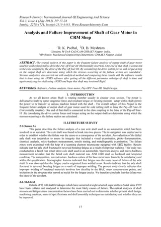
Fig. Shaft of gear motor and broken casing
Shaft of motor
which goes failure
5. Analysis And Failure Improvement Of Shaft…
21
V. DESIGN PROCEDURE
A) Power of Gear motor = 7.5 HP =5.5 KW
Rpm of gear motor = 41 rpm
Therefore Power of shaft P=
B) While the pay-off en-gauge with main rolling mill, as pay-off is used for providing the coil to the main
rolling mill system , and at instance that pay-off get dis-en-gauged ,while during the dis-en-gauging the pay -
off whole torque of mail rolling mill comes on the pay of and shaft of gear motor ,that drives the pay-off system
goes failure.
So, Power of motor that drives the main rolling mill P=1200KW
Initial rotation of rolls of main rolling mill is up to 300mpm i.e. Meter per minute = 300*1000= 300000 mmpm
i.e. mm per minute
Therefore circumference of roll =
Rpm of motor = 300000/786 = 381.97 rpm i.e. 382rpm
Power Of Motor P= (2πNT)/60
i.e. 1200*1000 = ( 2П*382*(T/60))
T =30000.146 N-m
C) Total Torque that come on the shaft of gear motor = Torque of gear motor + Torque of motor of main
system.
= 1281 + 30000 N-m
Tmax = 31281 N-m
D) Material and their properties of shaft of gear motor
Material of shaft of gear motor is SAE 4140
Sut/Syc =680Mpa
Sys =375Mpa
As considering Factor of Safety i.e. F.S = 1
Therefore Tensile /Bending stresses in shaft
6. Analysis And Failure Improvement Of Shaft…
22
And Shear stresses in shaft
E) Failure of shaft under Twisting moment
Tmax =
31281*1000 N-mm =
AS shaft is a step shaft having maximum diameter 60mm and minimum diameter of 40mm
So we consider minimum diameter for failure i.e. 40mm
given shear stress i.e. 375 N/mm2
For Maximum Bending moment
Ra + Rb = 11.38 KN
Taking moment at A
Ra*l = w*l*l/2 l – length of span = 1.55m
Ra =-w*l/2 = Rb
Ra = Rb = w*l/2 = 11.38 *(1.55/2) = 8.82 KN
Bending moment at A = 0,
Shear force at A
SFX = Ra – wx
If x = 0 m ,
SF0 =8.82 -11.38* 0 = 8.82KN
Bending moment at A x = 0
M0 = w/2* (x(l-x))
M0= (11.38/2)*(0(1.55-0))
M0= 0
For x = 1.55 m
SF 1.55 = -8.82KN
M 1.55 = 0
For x = 0.775 m
SF0.775 = 0 KN
M 0.775= 3.42 KN-m = 3.42*106 N-mm = 3420000 N-mm
Maximum bending Moment is Mmax= 3420 N-m
F) Failure of shaft under Bending
M =
3420*1000 = (π/16)*σb *403
σb = 544.31 N/mm2 ˂given bending stresses i.e. 680 N/mm2
Now, using Maximum Principle /normal stress Theory
=
= 2776.2N/ > 680 N/mm2
Minimum principle stresses are
=
= -2232.045 N/
Now, Using Maximum Principle / Normal shear stress Theory
7. Analysis And Failure Improvement Of Shaft…
23
=
Von Mises Stresses are =
i.e. Von MIses Stresses
G) Finding the Safe Diameter Of Shaft
According To Max. Shear stress Theory
Tmax =
31281*103 =(π/16)*375* d3
d =75.17 mm
According to Max. Normal Stress Theory
M =
3.42*106=(π/32)*680*d3
d = 37.134 mm
So we consider largest Diameter of Shaft as safe diameter i.e. d = 75.17 mm i.e 80mm
H) Re-Design of Shaft of Gear Motor According to Modified Diameter
Modified diameter of Shaft is d = 80 mm
So, According to max. Shear stress Theory
Tmax =
31281*103 =(π/16)* * 803
According to Max. Normal Stress Theory
M =
3.42*106=(π/32)* *803
It is proof that the safe diameter of Shaft is d = 80mm
VI. POSSIBLE DESIGN MODIFICATION
1. By Changing the material of good shear strength , the shaft may sustain in the maximum loading condition
2. Re-design the shaft with modified diameter and use in Scraped motor.
3. Select the Proper model of motor having the least diameter of shaft is more than 75mm.
4. Maintain the speed of both Gear motor and motor of cold rolling mill by installing new gear box for cold
rolling mill up to the
5. disengagement of Gear motor Shaft from pinch roll of Pay-OFF.
8. Analysis And Failure Improvement Of Shaft…
24
VII. COMPARING THE BOTH SOFTWARE AND ANALYTICAL RESULT
VIII. CONCLUSION
From the above Study it can be conclude that, the stresses find out by analytical method and by using
software both are nearly same and above the stresses of standard specimen.There are Four parameter to improve
the shaft life
[1] By changing the material of good shear strength, the shaft may sustain in the maximum loading
condition.
[2] Re-design the shaft with modified diameter and use in Scraped motor.
[3] Select the Proper no. of motor having the least diameter of shaft is more than 75mm.
[4] Maintain the speed of both Gear motor and motor of cold rolling mill by installing new gear box for
cold rolling mill up to the disengagement of Gear motor Shaft from pinch roll of Pay-OFF.
[5] All the above parameter that improves quality of shaft of gear motor leads to uneconomical for company.
REFERENCE
[1] Deepan Marudachalam M.G, K.Kanthavel, R.Krishnaraj “Optimization of shaft design under fatigue loading using Goodman
method International”, Journal of Scientific & Engineering Research Volume 2, Issue 8, August-2011 1 ISSN 2229-5518
[2] M.A.K. Chowdhuri , R.A. Hossain “Design Analysis of an Automotive Composite Drive Shaft “International Journal of
Engineering and Technology Vol.2(2), 2010, 45-48
[3] NICHOLAS and J.R. ZUIKER T. NICHOLAS and J.R. ZUIKER “On the use of the Goodman diagram for high cycle fatigue
design”, International Journal of Fracture 80: 219-235, 1996
[4] M. Ristivojevic, R. Mitrovic, T. Lazovic ,”Investigation of causes of fan shaft failure “,Engineering Failure Analysis , (2010)
1188–1194
[5] Saleh A. Al-Fozan, Anees U. Malik and Mohammad Al-Hajri , “FAILURE ANALYSIS OF SHEARED SHAFT OF A BRINE
RECYCLE PUMP”.
[6] Amol Bagate1, V.S.Aher2 ,”AXLE SHAFT TORSIONAL FATIGUE LIFE EXPECTANCY “. Proceedings of the NCNTE-
2012, Third Biennial National Conference on Nascent Technologies Fr. C. Rodrigues Institute of Technology, Vashi, Navi
Mumbai, Feb 24-25, 2012
[7] Stuart H. Loewenthal “Design of Power Transmitting Shafts”
NASA Reference Publication 1123 July 1984
[8] Sandip Bhattacharyya a,*, A. Banerjee a, I. Chakrabarti a, S.K.
Bhaumik , “Failure analysis of an input shaft of skip drive gearbox” Engineering Failure Analysis 15 (2008) 411–419
[9] R.S. Khurmi and J.k . Gupta , A book on “Machine Design”.
Result Analytical Software
Max. Shear Stresses 2504.2 Mpa 2541Mpa
Result Analytical Software
Max. Shear Stresses 2504.2 Mpa 2541Mpa