
Recommended
Recommended
More Related Content
Similar to Simulation of Single Phase Active Power Factor Pre Regulator
Similar to Simulation of Single Phase Active Power Factor Pre Regulator (20)
More from ijtsrd
More from ijtsrd (20)
Recently uploaded
Recently uploaded (20)
Simulation of Single Phase Active Power Factor Pre Regulator
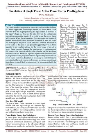
- 1. International Journal of Trend in Scientific Research and Development (IJTSRD) Volume 6 Issue 7, November-December 2022 Available Online: www.ijtsrd.com e-ISSN: 2456 – 6470 @ IJTSRD | Unique Paper ID – IJTSRD52594 | Volume – 6 | Issue – 7 | November-December 2022 Page 1291 Simulation of Single Phase Active Power Factor Pre-Regulator Dr. G. Madasamy Lecturer, Department of Electrical and Electronics Engineering, P.A.C. Ramasamy Raja Polytechnic College, Rajapalayam, Tamil Nadu, India ABSTRACT The objective of active power factor correction is to make the input to a power supply look like a simple resistor. An active power factor corrector does this by programming the input current in response to the input voltage. As long as the ratio between the voltage and current is a constant the input will be resistive and the power factor will be unity. When the ratio deviates from a constant, the input will contain phase displacement, harmonic distortion or both and either one will degrade the power factor. The most common definition of power factor is the ratio of real power to apparent power. A boost regulator is an excellent choice for the power stage of an active power factor corrector, because the input current is continuous and this produces the lowest level of conducted noise and the best-input current waveform. The boost regulator input current must be forced or programmed to be proportional to the input voltage waveform for power factor correction. Feedback is necessary to control the input current and either peak current mode control or average current mode control may be used. Both techniques may be implemented with the UC3854. KEYWORDS: Power Factor Correction (PFC), Active Power Factor Correction (APFC), Average Current Mode Control (ACMC) How to cite this paper: Dr. G. Madasamy "Simulation of Single Phase Active Power Factor Pre-Regulator" Published in International Journal of Trend in Scientific Research and Development (ijtsrd), ISSN: 2456- 6470, Volume-6 | Issue-7, December 2022, pp.1291-1294, URL: www.ijtsrd.com/papers/ijtsrd52594.pdf Copyright © 2022 by author (s) and International Journal of Trend in Scientific Research and Development Journal. This is an Open Access article distributed under the terms of the Creative Commons Attribution License (CC BY 4.0) (http://creativecommons.org/licenses/by/4.0) INTRODUCTION Most switching power supplies operates from a 50 or 60 Hertz AC line with a capacitive input filter. This type of filter draws current from the line only when the line voltage exceeds the filter capacitor voltage, and the filter capacitor is charged to near the peak level of the input line voltage. This means that the input current only flows for a short period near the peak of the input voltage waveform, causing the current to flow as a series of short, narrow pulses rather that the smooth, sinusoidal current that would result from a resistive load. How does PFC work? The goal of power factor correction is to make input current look like input voltage on a moment by- moment basis, the same as it would with a resistive load. Fig.1 Shows line voltage and line current with and without power factor correction. Power Factor Correction Techniques: In recent years, single-phase switch-mode ac-to-dc power converters have been increasingly used in the industrial, commercial, residential, aerospace, and military environment due to the advantage of high efficiency and smaller size and weight. However, the proliferation of the power converters draw pulsating input currents from the utility line, this not only results in poor power factor of the converters but also injects a significant amount of harmonic current into the utility. Fig.1 Effect of PFC on Line Current The power factor correction methods are classified as: (a) Passive power factor correction techniques and (b) Active power factor correction techniques Passive Power Factor Correction Technique: In this method an L-C filter is inserted between the AC mains line and the input port of the diode rectifier of ac-to-dc converter. This technique is simple and rugged but has bulky size and heavy weight and power factor cannot be very high. IJTSRD52594
- 2. International Journal of Trend in Scientific Research and Development @ www.ijtsrd.com eISSN: 2456-6470 @ IJTSRD | Unique Paper ID – IJTSRD52594 | Volume – 6 | Issue – 7 | November-December 2022 Page 1292 Active Power Factor Correction Technique: In this method, power electronics techniques are used to shape the input current drawn by the ac-to-dc converter in to a sinusoidal waveform and in phase with the input voltage. Thus, the power factor can reach almost unity and the ac to dc interface of the power converter emulates a pure resistor. Active Power Factor Correction: A boost regulator is the most popular choice for the power stage of an active power factor corrector, because the input current is continuous and this produces the lowest level of conducted noise and the best-input waveform. The output voltage must be greater than the highest expected peak input voltage. Boost regulator input current must be forced or programmed to be proportional to the input voltage waveform for power factor correction. Feedback is necessary to control the input current and either (i) peak current control or (ii) average current mode control may be used. Both techniques may be implemented with the UC3854 Principle of Average Current Mode Control: Average current mode control is based on a simple concept. An amplifier is used in the feedback loop around the boost power stage so that input current tracks the programming signal with very little error. This is the advantage of average current mode control and it is what makes active power factor correction possible. Average current mode control is relatively easy to implement. Basic Scheme of PFP with Average Current Mode Control: Fig.2 shows a boost PFP with average current control. The large bandwidth current error amplifier Gi(s) forces the input current, sensed by resistor Rs, to follow as close as possible a suitable sinusoidal reference signal. This latter is generated by multiplying a scaled version of rectified voltage Vg by the output of the voltage error amplifier. Thus, the voltage loop adjusts the current reference amplitude to keep the output voltage constant and equal to VREF. The third input of multiplier M1 is fed by a signal proportional to the line voltage RMS value obtained from vg by using a low-pass filter. This feed forward action helps the system response to line variations: in fact, with constant output power, an increase of the input voltage must correspond to a proportional decrease of the input current, which is provided by the feed forward path without need of voltage loop intervention. In the assumption of unity power factor and negligible input inductor energy, the fluctuating input power causes a low-frequency voltage ripple ∆vo across Co which depends only on the load current and is given by: Where is the line angular frequency (rad/s) and Po the output power. This holds provided that the voltage loop has a bandwidth well below the line frequency, in order to avoid variation of IREF (t) within the line cycle, which would cause input current distortion. To this purpose, a standard controller has a voltage loop bandwidth in the range 10-20Hz. This fact, gives a poor dynamic response to load variations. Fig.2 Basic Scheme of the Boost PFP with Average Current Mode Control
- 3. International Journal of Trend in Scientific Research and Development @ www.ijtsrd.com eISSN: 2456-6470 @ IJTSRD | Unique Paper ID – IJTSRD52594 | Volume – 6 | Issue – 7 | November-December 2022 Page 1293 Simulation Diagram of Single Phase Active Power Factor Pre-Regulator: SIMULINK is software package for modeling, simulating and analyzing dynamical system. It supports linear and nonlinear system, modeled in continuous time, sampled time, or a hybrid of the two; system can also be multirate, i.e., have different parts that are sampled or updated at different rates. Fig.3 shows the SIMULINK Block Diagram. Fig.4 shows the simulation output waveform. The comparison results are shown in Table I and the comparison graph is shown in Fig.5. Fig.3 Simulation Diagram for Single Phase Power Factor Pre-Regulator Simulation Output Waveform: Fig. 4 Input Line Voltage and Current Waveform at VIN=220V
- 4. International Journal of Trend in Scientific Research and Development @ www.ijtsrd.com eISSN: 2456-6470 @ IJTSRD | Unique Paper ID – IJTSRD52594 | Volume – 6 | Issue – 7 | November-December 2022 Page 1294 Simulation Test Results: Table I Simulation Results of Various Parameters at VIN=220V (With PFC) Load (%) Input line current (A) Power factor (p.u) THD (%) Output DC voltage (V) 20 9.20 0.9860 13.37 394 40 9.68 0.9893 12.15 394 60 10.75 0.9915 10.17 394 80 12.25 0.9930 9.75 394 100 13.5 0.9861 15.25 394 Fig.5 Output Power Vs THD for Various Input Voltage with PFC Conclusion: Single-phase Active Power factor pre-regulator simulation using MATLAB SIMULINK for various input voltages, the input voltage and input current waveforms are plotted. In converters, the main effort is devoted to the quality of the input current waveform but with the simple single switch topologies like the boost converters, the dynamic response of the output voltage is sacrificed. This is due to the input power fluctuation; the output voltage contains a low frequency ripple at twice the line frequency that affects the input current waveform unless the voltage loop bandwidth is kept below the line frequency (typically 20Hz). Simulation of single phase Active Power factor Pre regulator for various input voltage are performed using Simulink. The simulation results shows that for various input voltage and input current, power factor is nearly unity. The harmonics is reduced to 12%. In future, the harmonics is reduced to 5% such that the quality of input waveform is increased. References: [1] C. Zhou, “Design and Analysis of an Active Power Factor Correction Circuits, M.S. Thesis, Virginia Polytechnic Institute and state University, Sep.1989. [2] Dixon. U. H, “Average Current Mode Control of Switching Power Supplies”, Unitrode Power SupplyDesign Seminar SEM-700, 1990, pp.5-1 to 5-14 [3] N. Mohan, T. M. Undeland and W. P. Robbins, “Power electronics, converter, application, and design,” John Wiley & Son, Inc., New York, 1995, 2nd Edition. [4] P. C. Todd, “UC3854 Controlled Power Factor Correction Circuit Design”, U-134 Unitrode Application Note. [5] V. Ramanarayanan, “Intensive Course Switched Mode Power Supplies, Analysis, Modelling and Design”, Center for Continuing Education, Indian Institute of Science, Bangalore, India, 1990. [6] J. B. Williams, “Design of Feedback Loop in Unity Power Factor Converter,” IEEE Transaction on Power Electronics, Vol-6, no: 2, April 1991, pp.179 187. [7] The Math Works, Inc., “MATLAB Version 6.1 User Guide. [8] www.powerdesigners.com - Details about power supply design. [9] www.ridleyengineering.com - Details about control loop design. [10] www.ti.com - Details about IC UC3854.