Parametric Study of Double Layer Steel Dome with Reference to Span to Height Ratio

Optimum design of double layer dome of span to height ratio 2 and different supporting conditions(all bottom nodes supported, alternate bottom nodes supported and two alternate bottom nodes supported) for a given span is carried out. The formex programming software is used for configurations of double layer dome. The hollow circular pipe sections are used to construct the double layer dome and for connection, the MERO joint is used. Basically the dome have large exposed area so the wind force are predominant, hence the domes are analyze and design for wind forces. For optimum design of the structure, it is analyzed by using the software “SAP-2000-14”. In the analytical part, forces in the top layer are considered in groups and separate section will be designed for each group, the design will be based on IS800:2007. Similar procedure will be adopted for bracing system and bottom layer. The results are compared with different span to height ratios and support conditions for the deflection, weight of structure and concrete for pedestal, to determine optimum configuration by overall. The domes of span 75m with span to height ratio 2 as well as different support condition are designed for wind load. The members of dome are designed for axial tension and compression in such a way to get optimum weight of member.

Recommended
Recommended
More Related Content
What's hot
What's hot (20)
Similar to Parametric Study of Double Layer Steel Dome with Reference to Span to Height Ratio
Similar to Parametric Study of Double Layer Steel Dome with Reference to Span to Height Ratio (20)
More from International Journal of Science and Research (IJSR)
More from International Journal of Science and Research (IJSR) (20)
Recently uploaded
Recently uploaded (20)
Parametric Study of Double Layer Steel Dome with Reference to Span to Height Ratio
- 1. International Journal of Science and Research (IJSR), India Online ISSN: 2319-7064 Volume 2 Issue 8, August 2013 www.ijsr.net Parametric Study of Double Layer Steel Dome with Reference to Span to Height Ratio H. S. Jadhav1 , Ajit S. Patil2 1 Professor and Head, Civil Engineering Department, Rajarambapu Institute of Technology, Rajaramnagar, Islampur-415 409, (Dist: Sangli), Maharashtra, India 2 P. G. Student, Civil Engineering Department, Rajarambapu Institute of Technology, Rajaramnagar, Islampur-415 409, (Dist: Sangli), Maharashtra, India Abstract: Optimum design of double layer dome of span to height ratio 2 and different supporting conditions(all bottom nodes supported, alternate bottom nodes supported and two alternate bottom nodes supported) for a given span is carried out. The formex programming software is used for configurations of double layer dome. The hollow circular pipe sections are used to construct the double layer dome and for connection, the MERO joint is used. Basically the dome have large exposed area so the wind force are predominant, hence the domes are analyze and design for wind forces. For optimum design of the structure, it is analyzed by using the software “SAP-2000-14”. In the analytical part, forces in the top layer are considered in groups and separate section will be designed for each group, the design will be based on IS800:2007. Similar procedure will be adopted for bracing system and bottom layer. The results are compared with different span to height ratios and support conditions for the deflection, weight of structure and concrete for pedestal, to determine optimum configuration by overall. The domes of span 75m with span to height ratio 2 as well as different support condition are designed for wind load. The members of dome are designed for axial tension and compression in such a way to get optimum weight of member. Keywords: Double layer steel dome, span to height ratio, IS 800-2007. 1. Introduction Architects and engineers are always seeking new ways of solving the problem of space enclosure. The search for new structural forms to accommodate large unobstructed areas has always been the main objective of architects and engineers. With the industrialization and development of the modern world, there is a demand for efficient and adaptable long-span structures. Space structures are a valuable tool for the architect or engineer in the search for new forms, owing to their wide diversity and flexibility. A growing interest in space frame structures has been witnessed worldwide over the last half century. With the advent of new building techniques and construction materials, space frames frequently provide the right answer and satisfy the requirements for lightness, economy, and speedy construction. Significant progress has been made in the process of the development of the space frame. A large amount of theoretical and experimental research programs was carried out by many universities and research institutions in various countries. As a result, a great deal of useful information has been disseminated and fruitful results have been put into practice. Most structures in common use consist of elements such as beams, columns, trusses and portal frames which are basically two dimensional structural members, the point of view of analysis as well as design. Interconnecting members in the third dimension (e.g. purlins) are always of a secondary character, present merely for the purpose of transferring load and not supporting function of the structure. The fundamental advantage and economy of a form of structural assembly in which there is integrated load sharing is obvious, since every part of the structure makes an effective contribution. In such a system no single member is necessarily a principle one and failure in an individual member is not a matter of structural consequence. Space structure in which the above three dimensional function is realized are thus of considerable importance. These structures are being used in the construction industry to an increasing extent. They essentially involve analysis and design in three rather than two dimension. 2. Significance and Relevance A space structure is a structural system in the form of a three dimensional assembly of elements, resisting loads which can be applied at any point, inclined at any angle to the surface of the structure and acting in any direction. The individual members may be made up of rolled, extruded or fabricated sections. The three dimensional character includes flat surfaces with loading perpendicular to the plane as well as curved surfaces. The space frame can be constructed either in a flat or a curved surface. The earliest form of space frame structures is a single layer grid. By adding intermediate grids and including rigid connecting to the joist and girder framing system, the single layer grid is formed. The major characteristic of grid construction is the omni-directional spreading of the load as opposed to the linear transfer of the load in an ordinary framing system. Since such load transfer is mainly by bending, for larger spans, the bending stiffness is increased most efficiently by going to a double layer system. The load transfer mechanism of curved surface space frame is essentially different from the grid system that is primarily membrane-like action. As per the state of the art report by IASS (International association for shell and special structures), space frames are defined as below “A space frame is a structural system assembled of linear elements which transfers the forces in 110
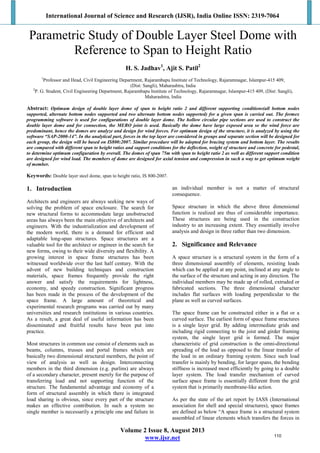
- 2. International Journal of Science and Research (IJSR), India Online ISSN: 2319-7064 Volume 2 Issue 8, August 2013 www.ijsr.net three dimensional manners. In some cases constituent elements may be two dimensional. Macroscopically, a space frame often takes the form of flat or curved surface”. A distinction sometimes is made between space frames and space trusses. According to this, space trusses are those systems which have pinned jointed members. Space frames are those which have rigid jointed members. However, as per the definition of Makowski and IASS, the word space frame is used as a generic term of which space trusses are the subpart of it. 3. Objectives of Present Work 1) To prepare an analytical model of double layer steel dome with the help of Software FORMEX. Model is then analyzed by SAP-2000. 2) To perform the parametric study of the effect of deflection and weight with reference to span to height ratio 2 and bottom supports. 4. Theoretical Background In the past few decades, the proliferation of the space frame was mainly due to its great structural potential and visual beauty. New and imaginative applications of space frames are being demonstrated in the total range of building types, such as sports arenas, exhibition pavilions, assembly halls, transportation terminals, airplane hangars, workshops, and warehouses. They have been used not only on long-span roofs, but also on mid- and short-span enclosures as roofs, floors, exterior walls, and canopies. Many interesting projects have been designed and constructed all over the world using a variety of configurations. Space structure is not a new type of structural system. During the past two centuries, thousands of these structures have been built in one form or another. Hundreds of publications concerning various aspects of their analysis, design and construction have been written and technology associated with these structures is highly developed in many areas. Some of the timber domes could be considered as forerunners of modern space structures. Since domes of the middle ages were mostly of solid masonry type with the timber construction primarily taking the form of frames or planar truss. Most of the interesting developments of space frame took place after the Young Leipzig engineer, August Foppl wrote his first book on Space structures under the title ‘Theory of Lattice systems’ in 1880. Among the few who appreciate Foppl’s theory of calculations of space frame was Gustave Eiffel who built the viewing tower of Paris – Eiffel Tower for the Paris exhibition of 1889.This is the first space structure built in steel with its calculation based on the three dimensional geometry. The tower was originally meant to be dismantle after the end of the exhibition, but turn out so well that it stand even today, not only the symbol of Paris, but also as a monument to the genius of its designer. The bridge over firth of forth at Queen Ferry was also erected in the year 1852-1890 and with the construction started the transition from plane to space frame. Despite of these splendid still structure which were erected in the second half of the nineteenth century and the book ‘Latticed structure in three dimension’ by Foppl in 1892, the difference between plane and space frame construction remained unknown to the majority of the building specialist for a number of years. 5. Modeling of Structure 5.1 Modeling by FORMEX Software The geometry of the double layer dome is prepared by using FORMEX software (programming language), for the Double layer dome, by the program are as follows Figure 1: Formex window for span to height ratio 2 111
- 3. International Journal of Science and Research (IJSR), India Online ISSN: 2319-7064 Volume 2 Issue 8, August 2013 www.ijsr.net 5.2 Modeling by SAP-2000: The model developed in formex software is then imported in SAP to further final model generation is as follows, Figure 2: Curved Models Figure 3: Angle in elevation for span to height ratio 2 6. Design of Dome Span of dome is 75 m and height is 37.50 m Table 1: Properties of Circular dome Spa n of dom e (m) Height of dome (m) Span to height ratio Sweep Angle Radius (m) 75 37.50 2 90 37.500 6.1 Load Combinations for Analysis of Domes: As per IS: 800-2007 1) 1.5(DL+LL), 2) 1.5(DD+WL), 3) 1.2(DL+LL+WL), 4) 0.9DL+1.2LL+1.2WL 6.2 Design of Tension Member In the member, tensile load is predominant than the compressive, member is designed for tension and cheek for compression. For dome of span to height ratio 2 the tension member design is as below as sample calculation. And remaining design of member is shown in table no. 3, 4, and 5. Design as per IS: 800-2007. Given Data: Loads: -Tensile = 57.69kN, Compressive = 19.69kN, Length of member = 3.96m, Yield stress (fy) =250 MPa, Modulus of elasticity (E) = 200000 N/mm2 . Step 1- Gross cross-sectional area (Ag) = (ɣmo × Tdg / fy)………... (IS800:2007, 6.2) Where Tdg is design tensile load ɣmo is partial safety factor for failure in tension by Yielding = 1.1 = [(1.1 x (57.69 x 1000)) / 250] = 1135.5564mm2 Step 2- Trial section Nominal Bore (mm) = 65, Outer diameter (mm) =76.1, Class = Light, Thickness (mm) = 3.2, Weight per meter (kg/m) = 5.754, Cross sectional area (mm2 ) = 732.966, Moment of Inertia (mm4 ) = 487848.267, Radius of Gyration (mm) = 25.799. Design strength of yielding (Tdg) = [(Ag × fy) / ɣmo] …….… (IS800:2007, 6.2) = [(732.966 x 250) / 1.1 x 1000] = 166.58kN. Section is Safe in tension. Step 3- Cheek for compression 112
- 4. International Journal of Science and Research (IJSR), India Online ISSN: 2319-7064 Volume 2 Issue 8, August 2013 www.ijsr.net Slenderness Ratio λ= (l/r) = 153.495 Euler buckling stress (fcc) = [(π² x E) / λ2 ] = 83.78 ______ Effective slenderness ratio (λe) = √ (fy/fcc) = 1.727 ______ Design compressive stress (fcd) = {(fy / ɣmo) / [Ф+ √ (Ф ²- λe²)]} ……………………… (IS800:2007, 7.1.2.1) Ф = 0.5[1+α (λe-0.2)+λe²] where α is Imperfection factor given in table 7 IS: 800- 2007. Ф = 0.5 x {1+ [0.34 x (1.727 – 0.2)] + (1.7272 ) } = 2.251 _______________ fcd = {(250/1.1) / [2.251+ √ (2.2512 + 1.7272 ) ]} fcd = 61.506 N/mm2 . Design compressive strength (Pd) = Ag x fcd = [(732.966 x 61.506)/1000] = 45.082kN. Section is Safe in compression. 6.3 Design of Compression Member In the member, the compressive load is predominant than tensile, member is design for compression and cheek for tension. For dome of span to height ratio 2 the compression member design is as below as sample calculation. And remaining design of member is shown in table no. 3, 4, and 5. Design as per IS: 800-2007. Given Data:- Loads: -Compressive = 19.69kN, Tensile = 57.69kN, Length of member = 3.96m, Yield stress (fy) =250 MPa, Modulus of elasticity (E) = 200000 N/mm2 . Step 1- Trial section Nominal Bore (mm) = 65, Outer diameter (mm) =76.1, Class = Light, Thickness (mm) = 3.2, Weight per meter (kg/m) = 5.754, Cross sectional area (mm2 ) = 732.966, Moment of Inertia (mm4 ) = 487848.267, Radius of Gyration (mm) = 25.799. Step 2- Calculation of Design compressive stress Slenderness Ratio λ = (l/r) = 153.495 Euler buckling stress (fcc) = [(π² x E) / λ2 ] = 83.78 ______ Effective slenderness ratio (λe) = √ (fy/fcc) = 1.727 _______ Design compressive stress (fcd) = {(fy / ɣmo) / [Ф + √ (Ф ²- λe²)]} ……………………… (IS800:2007, 7.1.2.1) Ф = 0.5[1+α (λe-0.2)+λe²] Where α is Imperfection factor given in table 7 IS: 800- 2007. Ф = 0.5 x {1+ [0.34 x (1.727 – 0.2)] + (1.7272 )} = 2.251 _______________ fcd = {(250/1.1) / [2.251+ √ (2.2512 + 1.7272 ) ]} fcd = 61.506 N/mm2 . Design compressive strength = Ag x fcd …………………... (IS800:2007, 7.1.2) = [(732.966 x 61.506)/1000] = 45.082kN. Section is Safe in compression. Step 3- Cheek for Tension Design strength of yielding (Tdg) = [(Ag × fy) / ɣmo] ….… (IS800:2007, 6.2) = [(732.966 x 250) / 1.1 x 1000] = 166.58kN. Section is Safe in tension. 6.4 Design of Foundation For dome of Span to height ratio 2 the footing design is as below as sample calculation. And remaining design of footing is shown in table no. 5 Given Data:- Shear forces: - Fx = 198.37kN, Fy = 224.39kN. Vertical load Fz (Pu) = 360.063kN. Bearing capacity of soil = 350kN/m2 . fy =250 MPa; Concrete grade fck = M-20. 6.4.1 Design of base plate Step 1- Bearing Stress in concrete fb fb= 0.6 x fck ………………………... (IS800:2007, 7.4.1) fb = 0.6 x 20 fb = 12 N/mm2 . Step 2- Required Area of Base Plate = [Pu/ (0.6 fck)] Where Pu is the factored concentric load on footing = [(360.063 x 1000)/12] = 30005.25 mm2 Step 3- Provide Square Plate ________ Length of base plate = √30005.25 = 173.22mm. So provide 200mm x 200mm Base Plate. Step 4- Calculate the intensity of pressure w acting below the base plate using w = (Pu / A1) Where A1 is the provided area of base plate (L x B) w = [(360.063 x 1000)/ (200 x 200)] w = 9.00 N/mm2 . 113
- 5. International Journal of Science and Research (IJSR), India Online ISSN: 2319-7064 Volume 2 Issue 8, August 2013 www.ijsr.net Step 5- Calculate minimum thickness of base plate ____________________ tp = √[2.5w (a²-0.3b²) ɣmo /fy ] Where, w pressure on the underside of base plate. a and b are the larger and smaller projection of base plate. Assume square plate (a = b) fy is the yield strength of base plate. _______________________________ tp =√ [2.5 x 9 x (502 – 0.3 x 502 ) x 1.1/250] tp = 13.16 mm. Provide thickness of base plate is 16mm. 6.4.2 Design of anchor bolt: Assume the diameter of Anchor bolt is 24mm and Grade of bolt 4.6 Step 1- Shear strength of bolt in Single shear ______ = {[fu / (√3 x ɣmo)] Asd} Where fu is the ultimate strength of bolt, Asd is the tensile stress area. Ф _______ = {[400 / (√3 x 1.25)] x 361.91} = 69.65kN For Double shear strength = 2 x 69.65 = 139.33kN Step 2- Bearing strength of bolt = 2 x d x tp x fu Where tp is thickness of plat = 2 x 24 x 16 x 400 = 307.20kN .∙. Rivet value (R) = 139.33kN Step 3- Number of bolts required = (Pu/R) = (360.063/139.33) =2.58 .∙. Provide 4 No. of 24mm Ø anchor bolts. Step 4- Cheek for Shear _____________ Resultant Shear (Fr) = √ [(Fx2 ) + (Fy2 )] ___________________ = √ [(198.37)2 + (224.39)2 ] = 299.50kN Bolts required for resultant shear = (299.50 / 139.33) = 2.15 .∙. Provided anchor bolts are Safe. Step 5- Length of anchor bolt Tensile stress of bolts (σtb) = 272 N/mm2 . Modular ratio (m) = 18 a) Calculate the depth of neutral axis Length of base plate = 350mm, Edge distance provided (r) = 50mm. Moment at bolt line = {12 x (502 / 2)} = 15kN.mm d = 375-50 = 325mm n = d . {1+ [ σtb / (m + fb )]} n = 143.85mm Lever arm = [d-(n/3)] = 277.05mm. b) Compressive force at bolt line C x [d-(n/3)] = M + Pu x [(L /2) – r] C x 277.05 = 15 + 360.063 x [(375/2) – 50] C = 178.75kN. c) Tension in wind word direction P1 = Pu – C = 360.063 – 178.75 = 181.31kN. d) Length of anchor bolt L = (P1 / 2) . 2 x π x d x bound stress L = (181.31 / 2) . 2 x π x 24 x 1.2 L = 501.23 Provide length of anchor bolt is 510mm. 6.4.3 Design of pedestal: Required area of pedestal = [(360.063 x 1.1) / (350 x 1.5)] = 0.7544m2 Area of plate = 200mm x 200mm _______ Length of pedestal Lf = √ 0.7544 = 0.8686mm Provide size of pedestal = 900mm x 900mm. Actual maximum projection = (900 – 375)/2 = 262.5mm Giving slope of 1:1, there for depth of pedestal = 350mm. Actual weight of the pedestal = 1.5 x 24 x 0.90 x 0.90 x 0.35 = 10.206kN. Actual bearing stress of soil = (360.063 + 10.206) / (0.90 x 0.90 x 1.5) = 304.75kN < 350kN/m2 . OK. Provide base plate 375 x 375 x 16 mm, Concrete pedestal 900 x 900 x 525 mm, Anchorage bolts 4 No. of 24mm Ø x 510mm long. 114
- 6. International Journal of Science and Research (IJSR), India Online ISSN: 2319-7064 Volume 2 Issue 8, August 2013 www.ijsr.net Table 2: Wind load on dome of span to height ratio 2 Node No. Cartesian co- ordinates Sperical coordinates Cpe Cpi Area (Sqm) F Normal to Surface (kN) Fx (kN) Fy (kN) Fz (kN)X Y Z θ Φ (m) (m) (m) (deg) (deg) 1 4.18 0 39.78 6 0 -1 0.2 15.36 -17.06 -1.78 0 -17 2 2.09 3.62 39.78 6 60 -1.2 0.2 15.36 -19.9 -1.04 -1.8 -19.8 3 -2.09 3.62 39.78 6 120 -1.2 0.2 15.36 -19.9 1.04 -1.8 -19.8 4 -4.18 0 39.78 6 180 -1.2 0.2 15.36 -19.9 2.08 0 -19.8 5 -2.09 -3.6 39.78 6 240 -1.2 0.2 15.36 -19.9 1.04 1.8 -19.8 6 2.09 -3.6 39.78 6 300 -1.2 0.2 15.36 -19.9 -1.04 1.8 -19.8 7 20.08 0 45.11 11 0 -0.8 0.2 15.88 -14.7 -2.8 0 -14.4 8 17.39 10 45.11 11 30 -0.8 0.2 16.11 -14.91 -2.46 -1.42 -14.6 9 10.04 17.4 45.11 11 60 -1 0.2 15.88 -17.64 -1.68 -2.91 -17.3 10 0 20.1 45.11 11 90 -1 0.2 16.11 -17.89 0 -3.41 -17.6 11 -10 17.4 45.11 11 120 -1 0.2 15.88 -17.64 1.68 -2.91 -17.3 12 -17.4 10 45.11 11 150 -1 0.2 16.11 -17.89 2.96 -1.71 -17.6 13 -20.1 0 45.11 11 180 -1 0.2 15.88 -17.64 3.37 0 -17.3 14 -17.4 -10 45.11 11 210 -1 0.2 16.11 -17.89 2.96 1.71 -17.6 15 -10 -17 45.11 11 240 -1 0.2 15.88 -17.64 1.68 2.91 -17.3 16 0 -20 45.11 11 270 -1 0.2 16.11 -17.89 0 3.41 -17.6 17 10.04 -17 45.11 11 300 -1 0.2 15.88 -17.64 -1.68 2.91 -17.3 18 17.39 -10 45.11 11 330 -0.8 0.2 16.11 -14.91 -2.46 1.42 -14.6 Table 3: Foundation Details S. No Span to Height ratio Support Condition Size of base plate mm Thickness of Plate mm No. & Dia. of Anchor bolt Length of Anchor bolt mm Pedestal size mm Hub Dia. Mm Weld length of plate & hub (mm) 1 2 All Node 375 x 375 16 8-24mm Ø 410 1000x1000x 425 125 375 2 2-A Alternate Node 450 x450 20 8-30mm Ø 530 1250x1250 x 550 200 628.4 3 2-A 2-Alternate Node 550 x 550 16 12-36mm Ø 425 1500x1500 x 450 300 800 7. Discussion of Result The domes of span 75m with span to height ratio 2 as well as different support condition are designed for wind load. The members of dome are designed for axial tension or compression in such a way to get optimum weight of member. The results in fig. 4 to 10 shows the weight of base plat, volume of concrete for pedestal, weight of member and deflection of domes. 7.1 Weight of Dome Table 4: Weight of base plate and volume of concrete Span (m) Height (m) Span to Height ratio Radius (m) Sweep Angle (deg.) Support Condition No. of footing Base plate weight kN Volume of Concrete m3 75 37.5 2 37.5 90 All node 192 46.75 97.2 Alternate node 96 40.64 107.34 Two alternate node 64 34.99 90.40 Table no. 4 and fig. 4, 6 shows the weight of base plate and the volume of concrete of pedestal. Also it is categorized for different support conditions. It is clear that for span to height ratio 2, and bottom support is two alternate nodes the base plate weight is very less and volume of concrete is also less than other support conditions. So the weight of dome gets reduced. 115
- 7. International Journal of Science and Research (IJSR), India Online ISSN: 2319-7064 Volume 2 Issue 8, August 2013 www.ijsr.net Figure 4: Weight of base plate Here fig. 4 shows the comparison of weight of base plate with different support conditions, in this two alternate bottom nodes supported conditions gives minimum weight of base plate. Figure 5: Volume of concrete for pedestal Here fig. 5 shows the comparison of volume of concrete for pedestal with different support conditions, in this two alternate bottom nodes supported conditions gives minimum volume of concrete for pedestal. Table 5: Weight of dome Span (m) Height (m) Span to Height ratio Radius (m) Sweep Angle (deg.) Support Condition Weight Max. Compression (KN) Max Tension (kN) (kN) 75 37.5 2 37.5 90 All node 15428.51 162.393 108.672 Alternate node 15792.93 270.942 119.317 Two alternate node 15595.61 371.686 157.721 Figure 6: Weight of members The Table No. 5 and fig. 6 shows the weight of dome for different supporting condition, with Span to Height ratio 2 (all bottom nodes supported) gives lowest weight 2.18 kN/m2 derived from all cases. 7.2. Deflection of Dome The following figures show the deflection of dome [fig. 7 to 10] for different support condition, the maximum deflection of different domes is tabulated in table No. 6. Figure 7: Deflection of Span to Height ratio 2 at all bottom nodes supported 116
- 8. International Journal of Science and Research (IJSR), India Online ISSN: 2319-7064 Volume 2 Issue 8, August 2013 www.ijsr.net Figure 8: Deflection of Span to Height ratio 2 at alternate bottom nodes supported Figure 9: Deflection of Span to Height ratio 2 at two alternate bottom nodes supported Table 6: Deflection of dome Spa n (m) Heig ht (m) Span to Heig ht ratio Radiu s (m) Swee p Angl e (deg. ) Support Condition Max. Deflecti on (m) 75 37.5 2 37.5 90 All node 0.04348 Alternate node 0.03980 Two alternate node 0.04051 Figure 10: Deflection of domes 8. Conclusion After reviewing the intact procedure which involves analytical study, design of member, design of foundation with reference to aim of work it can be concluded that: 1. In case of span to height ratio 2 the deflection observed in dome of alternate bottom node supported is less compared to other two cases. 2. From comparisons of all cases in span to height ratio 2, at all bottom nodes support gives minimum member weight (10%-60% reduction in weight) than other cases. 3. In case of two alternate bottom nodes support gives minimum base plate weight (65%-80% reduction in weight) than other cases. 4. The concrete volume of pedestal in case of all bottom nodes supported is less (25%-65% reduction) as compared to other cases. From the present study it is concluded that, considering deflection, member weight, base plate weight and pedestal size; the span to height ratio 2 with all bottom nodes supported proves to be the optimum design for a span of 75m double layer geodesic dome. References [1] Vesmawala G. R., Dr. J. A. Desai, Dr. H. S. Patil, “Parametric study of lamella domes for optimum shape design”.(2003) [2] Shah, B J; Dr. H. S. Patil, “Discrete Optimization of Double layer grid supported on periphery using AI Technique”. ”.(2003) [3] H. Nooshin and P. Disney, “Elements of Formian” Space Structures Research Centre, Department of Civil Engineering, University of Surrey, Guildford, Surrey GU2 5XH, U.K. (2005) [4] L. J. Li, Z. H. Xie, Y. C. Guo, F. Liu, “Structural optimization and dynamic analysis for double-layer spherical reticulated shell structures”. Journal of Constructional Steel Research vol. no 62,(2006), page no. 943-949. [5] M. M. Alinia, S. Kashizadesh, “Effects of support positioning on thermal behavior of double –layer space truss domes.” Journal of Construction Steel Research vol. no. 63(2007) page no. 375-382. [6] Bhavikatti S. S., Itti S. V., Lakshmy T. K.,“Optimum design of single braced 3D-poly steel domes with central opening”. [7] El-Sheikh, A.I., and El-Bakry. H., “Experimental Study of Behavior of New Space Frame Truss System” Journal of Structural Engineering, ASCE Vol.22, No.8, pp845-853.(2007) [8] IS800:2007. “General Construction in Steel- Code of Practice” Bureau of Indian Standards. [9] IS806:1986. “Code of Practice for use of Steel Tubes in General Building Construction” Bureau of Indian Standards. [10]IS875:1987. “Code of Practice for design load (other than earthquake) for Building and structures” Bureau of Indian Standards, (part-II) Imposed load. 117
- 9. International Journal of Science and Research (IJSR), India Online ISSN: 2319-7064 Volume 2 Issue 8, August 2013 www.ijsr.net [11]IS875:1987. “Code of Practice for design load (other than earthquake) for Building and structures” Bureau of Indian Standards, (part-III) Wind load. [12]SAP2000-14, Integrated solution for structural analysis and design. Author Profile Dr. H. S. Jadhav is Professor and Head of Civil Engineering Department; Rajarambapu Institute of Technology, Rajaramnagar, Islampur-415 409, (Dist: Sangli), Maharashtra-India 118