Safety Optimization in Bikes

Introduction of fast moving bikes in our country has disturbed the condition of Indian roads. Rash driving is the major concern with these bikes which has led to accidents all over. Today's generation which normally prefer super bikes (150cc or more) accounts for most of the accidents taking place in the country. Comparing previous census, the number of accidents taking place have increased drastically. Though bikes have high safety systems like disc brake, ABS, etc which can arrest the motion of wheel and stop the vehicle at any speeds, the problem here arises with pillion rider. When braking is applied at high speeds, the rear wheel is lifted up and bike comes to stoppie position and throws off the pillion rider from the vehicle. Pillion riders hardly wear helmet, thus it leads to serious injuries even leading to death. To minimize these kind of accidents, a special kind of shock absorber has been designed which absorbs shocks to greater extent. This shock absorber uses slider mechanism supported by springs placed beneath the rear seat. The rear seat is fitted with rollers which slide inside the rail, thus providing a slider motion. This slider motion is supported by springs of calculated stiffness which returns the roller to initial position after the action. When there is sudden breaking, deceleration is produced which brings the slider mechanism in action. The roller moves forward which leads to movement of seat forward and also the pillion rider. This pushes pillion rider forward rather than being thrown off from the vehicle. The spring plays a vital as it brings back the seat to initial position after the action is performed. Spring has another advantage as it reduces the shock produced during the movement of seat back and forth due to sudden breaking. Implementation of this method is easy as it requires slight customization in the rear seat. The rear seat is separated from driver's seat and slider mechanism is made beneath the rear seat. Setting up of this shock absorber is cheap and affordable.

Recommended
Recommended
More Related Content
What's hot
What's hot (19)
Similar to Safety Optimization in Bikes
Similar to Safety Optimization in Bikes (20)
More from ijsrd.com
More from ijsrd.com (20)
Recently uploaded
Recently uploaded (20)
Safety Optimization in Bikes
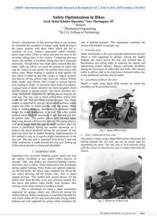
- 1. IJSRD - International Journal for Scientific Research & Development| Vol. 1, Issue 9, 2013 | ISSN (online): 2321-0613 All rights reserved by www.ijsrd.com 1961 Abstract--Introduction of fast moving bikes in our country has disturbed the condition of Indian roads. Rash driving is the major concern with these bikes which has led to accidents all over. Today’s generation which normally prefer super bikes (150cc or more) accounts for most of the accidents taking place in the country. Comparing previous census, the number of accidents taking place have increased drastically. Though bikes have high safety systems like disc brake, ABS, etc which can arrest the motion of wheel and stop the vehicle at any speeds, the problem here arises with pillion rider. When braking is applied at high speeds, the rear wheel is lifted up and bike comes to stoppie position and throws off the pillion rider from the vehicle. Pillion riders hardly wear helmet, thus it leads to serious injuries even leading to death. To minimize these kind of accidents, a special kind of shock absorber has been designed which absorbs shocks to greater extent. This shock absorber uses slider mechanism supported by springs placed beneath the rear seat. The rear seat is fitted with rollers which slide inside the rail, thus providing a slider motion. This slider motion is supported by springs of calculated stiffness which returns the roller to initial position after the action. When there is sudden breaking, deceleration is produced which brings the slider mechanism in action. The roller moves forward which leads to movement of seat forward and also the pillion rider. This pushes pillion rider forward rather than being thrown off from the vehicle. The spring plays a vital as it brings back the seat to initial position after the action is performed. Spring has another advantage as it reduces the shock produced during the movement of seat back and forth due to sudden breaking. Implementation of this method is easy as it requires slight customization in the rear seat. The rear seat is separated from driver’s seat and slider mechanism is made beneath the rear seat. Setting up of this shock absorber is cheap and affordable. I. INTRODUCTION Superbikes have powerful breaking system which can stop the vehicle travelling at any speed within fraction of seconds. ABS, disc brakes are advanced braking systems used these days in bikes. These brakes have few drawbacks during sudden braking. When brakes are applied suddenly, say 80-100 km/hr, the wheel stops suddenly but lift up the rear wheel throwing off the pillion rider. This is called stoppie position. This sudden jerk caused throws off the pillion rider from the bike as he gets seriously injured. We also know that pillion riders hardly wear helmets, thus causing serious brain injuries or leading to death. This is eliminated by using a slider mechanism supported by springs which acts effectively during the sudden braking. Slider mechanism is assembled beneath the seat which slides off the seat back and forth during sudden braking and well supported by spring which maintains the seat in definite position. This mechanism maintains the system functionality in a proper way. A. Principle used: Slider mechanism is the main principle behind this process which is well supported by springs. During the sudden braking, the slider moves the rear seat forward due to deceleration and spring helps in reducing the shocks and maintaining proper balance. Spring maintains flexibility during the movement of slider back and forth. This ensures safety to pillion rider as he experiences forward motion due to the mechanism and this ensures safety. B. Assembling of Shock absorber: Model is made using Bajaj M80 scooter on which the assembly can be performed easily. Fig. 1: Bajaj M80 scooter C. Step 1: Removal of rear seat: The model is made using a Bajaj M80 scooter which has flat bottom beneath the rear seat and can be easily used for assembling the parts. The rear seat is first removed along with the carrier so that the rear area is empty other than the chassis. Fig. 2: Removal of Rear seat Safety Optimization in Bikes Syed Abdul Khader Hussainy1 Neer Mariappan. M2 1, 2 Student 1, 2 Mechanical Engineering 1,2 K.C.G. College of Technology
- 2. Safety Optimization in Bike (IJSRD/Vol. 1/Issue 9/2013/0066) All rights reserved by www.ijsrd.com 1962 D. Step 2: Arrangement of Rails: Fig. 3: Arrangement of Rails The next step is arrangement of bars in form of rails which can provide effective slider mechanism. Two U-shaped bars are placed parallel to each other using cross links so that there is strong support between the rails and also the chassis. These rails are arranged in a proper way and welded along with the chassis. These rails form slider mechanism for the rear seat. E. Step 3: customized rear seat with rollers: The rear seat is customized using the dimensions of the rail and rollers are fixed on the seat using screws. The distance between two rails is considered in fixing the rollers on the seat. These rollers slide between the channels. Fig. 4: Fixing of rollers F. Step 4: Spring Design: The braking force is calculated using the torque produced while applying sudden brake. This braking force is used in calculating the spring stiffness. The deflection in spring is calculated using the load applied. Finally, analysis is done using these values to calculate the maximum load spring can withstand and designed accordingly. Fig. 5: Spring Design G. Step 5: Spring Assembly: The spring is then fitted to the rear seat and other end of spring is affixed to the chassis. This completes the assembly of the shock absorber as the slider is now ready to slide between the rails and spring acts accordingly. Fig. 6: Spring Assembly H. Final Product: Fig. 7: Final Product I. Model Calculations: 1) Breaking torque Calculation: To calculate breaking force, ( ) ( ⁄ ) Where, PL - Brake line pressure N/mm2. PO - Push out pressure N/mm2 AWC -Cross sectional area of wheel cylinder piston mm2 BF - Braking factor R - Tire Radius mm r- Effective radius of disc mm. ηC -Wheel cylinder efficiency 2) Calculation of Brake line pressure Where, FP - Pedal Force, N Lp - Pedal Lever ratio Amc - Cross sectional area of master cylinder, mm2 . ηp - Pedal Lever Efficiency Diameter of the master cylinder piston is 15mm 3) Calculation of cross sectional area of the master cylinder =176.7145 mm2
- 3. Safety Optimization in Bike (IJSRD/Vol. 1/Issue 9/2013/0066) All rights reserved by www.ijsrd.com 1963 And the brake line pressure is, =9.26692 N/mm2 4) The diameter of the piston of the wheel cylinder is 25mm.The area is, = 490.8738 mm2 Since there are two such cylinders, the area is multiplied. Therefore, Total area = 490.8738*2 =981.7476 mm2 5) The brake factor for a non-self-energizing disc brake is 2µL Therefore, BF = 2*0.35 BF= 0.7 6) The effective radius of the disc is given by, Where, D- Outer Diameter of disc in mm d- Inner Diameter of disc in mm r = 78.75 mm The push out pressure for a disc brake is negligible and can be ignored. Therefore the braking force is, FX = 9.26692 * 981.7476 * 0.98 * 0.7 * (78.75/317.5) =1547.9830 N The braking torque achieved by the braking system is found by multiplying the force with the radius of the wheel. Therefore, Torque achieved = 1547.9830*317.5 = 491484.6025 N-mm Hence the brake torque achieved by the braking system is 491.484 N-m J. Reaction force Fig. 8: Diagram for finding Reaction Force Taking moment about point B, ⁄ ( ) ( ) ( ) Reaction force 1) Spring Calculation Assuming load and deflection, ⁄ K. Summary The model is made using Bajaj M80 bike which has flat bottom part beneath the rear seat. The assembly of shock absorber is easy. Therefore, the purpose of selecting this scooter rather than selecting a bike is that it is convenient to assemble all the parts as just model is been made. This assembly can later be used in bikes for the purpose of testing and implementation. As discussed earlier, we can imagine this shock absorber system in the bikes. During the sudden breaking, deceleration is produced which leads to sliding of the rollers between rails which causes forward motion of the rear seat and also pillion rider. Spring maintains flexibility in the movement and also reduces the shock. The spring is designed and selected accordingly that it can withstand any value of load produced. Also, it is effective at any speed and breaking effect produced. At various speeds and loads the system acts accordingly and no adjustments are to be made. This shock absorber can be applied in bikes more than 150cc to have greater effect and extra safety to the pillion rider. II. CONCLUSION This topic mainly deals with the safety of the pillion rider. Assembling of this system can add more safety to the pillion rider as it can reduce higher values of shocks produced. Installing of this system is cheap and can be easily assembled in any bike. Further research and development on this product can lead to application in commercial way and better results can be obtained. In future, the two wheelers can be made with this type of assembly. ACKNOWLEDGEMENT We heartily wish to express our obedient and sincere thanks to our Management for having offered the facilities required for the successful completion of the project. We express our deep gratitude to Dr. T. Rengaraja, Principal, K. C. G.
- 4. Safety Optimization in Bike (IJSRD/Vol. 1/Issue 9/2013/0066) All rights reserved by www.ijsrd.com 1964 College of Technology for his motivation and encouragement in every step of our course. We give our heartfelt thanks to Dr. Z. Edward Kennedy, Head of the department, Mechanical Engineering for giving valuable guidance, constant support and encouragement to complete our project successfully .We are highly indebted to our guide, Mr. D. Easu for his kind and valuable guidance and suggestion in every stage of our project and to make our project a successful one. We would also like to thank Mrs. Sumathi Poobal, Vice principal, K.C.G. College of Technology and Mr. Dhorai Thodla for their immense co-operation and encouragement throughout this project, also spending all their precious time with us. With deep feeling of indebtedness we owe many special and heartfelt thanks to all teaching and non-teaching staff members for their complete co-operation, help and suggestions. REFERENCES [1] R.S. Khurmi and J.K. Gupta “Textbook of Machine Design” [2] Rudolph limpert “Brake Design and Safety”