Gq3311661169
•
0 likes•182 views

International Journal of Engineering Research and Applications (IJERA) is an open access online peer reviewed international journal that publishes research and review articles in the fields of Computer Science, Neural Networks, Electrical Engineering, Software Engineering, Information Technology, Mechanical Engineering, Chemical Engineering, Plastic Engineering, Food Technology, Textile Engineering, Nano Technology & science, Power Electronics, Electronics & Communication Engineering, Computational mathematics, Image processing, Civil Engineering, Structural Engineering, Environmental Engineering, VLSI Testing & Low Power VLSI Design etc.

Recommended
Recommended
More Related Content
What's hot
What's hot (20)
Viewers also liked
Viewers also liked (20)
Similar to Gq3311661169
Similar to Gq3311661169 (20)
Recently uploaded
Recently uploaded (20)
Gq3311661169
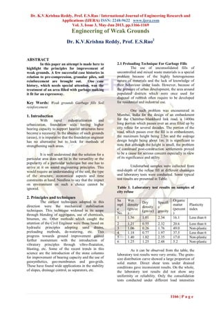
- 1. Dr. K.V.Krishna Reddy, Prof. E.S.Rao / International Journal of Engineering Research and Applications (IJERA) ISSN: 2248-9622 www.ijera.com Vol. 3, Issue 3, May-Jun 2013, pp.1166-1169 1166 | P a g e Engineering of Weak Grounds Dr. K.V.Krishna Reddy, Prof. E.S.Rao2 ABSTRACT In this paper an attempt is made here to highlight the principles for improvement of weak grounds. A few successful case histories in relation to pre-compression, granular piles, soil reinforcement are brought out. One case history, which needs special attention, was the treatment of an area filled with garbage making it fit for an expressway. Key Words: Weak grounds Garbage fills Soil reinforcement 1. Introduction With rapid industrialization and urbanization, foundation soils having higher bearing capacity to support heavier structures have become a necessity. In the absence of such grounds (areas), it is imperative that the foundation engineer has no alternative but to look for methods of strengthening such areas. It is well understood that the solution for a particular area does not lie in the versatility or the popularity of a particular technique but one has to arrive at it on sound engineering principles. This would require an understanding of the soil, the type of the structure, economical aspects and time constraints at hand. Needless to say that the impact on environment on such a choice cannot be ignored. 2. Principles and techniques The earliest techniques adopted in this direction were the mechanical stabilisation techniques. This technique widened in its scope through blending of aggregates, use of chemicals, bitumen, etc. Other methods which caught the attention of the Civil Engineer were those based on hydraulic principles adopting sand drains, preloading methods, de-watering, etc. This progress towards ground improvement gained further momentum with the introduction of vibratory principles through vibro-floatation, blasting, etc. Some of the recent trends in this science are the introduction of the stone columns for improvement of bearing capacity and the use of geosynthetics, geo-membranes and geo-grids. These have found wide applications in the stability of slopes, drainage control, as separators, etc. 2.1 Preloading Technique For Garbage Fills The use of unconsolidated fills of uncontrolled and mixed waste materials is a special problem because of the highly heterogeneous nature of materials and the lack of knowledge of their behaviour under loads. However, because of the pressure of urban development, the area around populated districts which were once used for disposal of rubbish often require to be developed for residential and industrial use. One such problem was encountered in Mumbai, India for the design of an embankment for the Chembur-Mankhurd link road, a 1400m long portion which passes over an area filled up by city refuse for several decades. The portion of the road, which passes over the fill is in embankment, the maximum height being 2.5m and the average design height being about 1m. It is significant to note that although the height is small, the problem of continued post-construction settlements proved to be a cause for serious concern especially in view of its significance and utility. Undisturbed samples were collected from mid-depth of the refuse fill at different chainages and laboratory tests were conducted. Some typical test results are presented in Table. Table 1. Laboratory test results on samples of city refuse Sa mpl e No. Wet density (gm/cc ) Dry density (gm/cc) Specifi c gravity Organic matter (percent ) Plasticity index 1 1.56 1.01 2.34 16.1 Less than 6 2 1.21 0.55 2.32 20.6 Less than 6 3 1.06 0.26 1.76 49.0 Non-plastic 4 1.18 0.77 1.97 37.5 Less than 6 5 1.40 1.02 2.35 17.0 Non-plastic 6 1.25 1.25 2.48 5.2 Non-plastic As it can be observed from the table, the laboratory test results were very erratic. The grain- size distribution curve showed a large proportion of solid matter. Direct shear tests under drained conditions gave inconsistent results. On the whole, the laboratory test results did not show any uniformity or reliability. Only the consolidation tests conducted under different load intensities
- 2. Dr. K.V.Krishna Reddy, Prof. E.S.Rao / International Journal of Engineering Research and Applications (IJERA) ISSN: 2248-9622 www.ijera.com Vol. 3, Issue 3, May-Jun 2013, pp.1166-1169 1167 | P a g e gave time-settlement curves, which followed a trend similar to those of peats. There were no well- defined stages of primary or secondary consolidation as are normally obtained in the case of inorganic clays. Realizing that the laboratory investigations do not provide any reliable basis for predicting the magnitude and the rate of settlement in the field as far as rubbish fills are concerned, a field test embankment was planned that could provide a meaningful and realistic basis for predicting both the magnitude as well as the rate of settlement of the prototype embankment. Thus, an embankment 60m long and 26m wide at top was raised in the refuse dump area to a height of 2.5m for a length of 45m and to a height of 3.7 m for the remaining length with side slopes of 1:2. Two different heights of embankment were adopted within the length of embankment so that he behaviour of test embankment could be seen under different load intensities. The embankment was fully instrumented with settlement platforms, displacement stakes and the Swedish Geotechnical Institute settlement gauge. The embankment was built up of moorum, the locally available granular material under strict quality control. A study of the observational data over a period of one year indicated that about 50% of the settlement took place almost instantaneously upon placement of load. Another 28% of the total settlement occurred over a period of the next 3 months. Yet another 12% occurred over a period of the next 3 months and finally, about 10% of the total settlement took place over the remaining period of 6 months. The observations continued for about 1 1/2 years. There was no significant heave in any of the displacement stakes. There was also no noticeable rebound observed upon removal of load. It would, therefore, seem that the settlement characteristics of a rubbish fill are, by and large, similar to those of peats. It appears that there is no reason to believe that the rubbish fill would by itself constitute a serious source of continuing significant settlements, beyond a period of 1 year by which time more than 90% of total settlement occurs. The simple technique of preloading can be effectively used for treating rubbish fills in comparison to the use of light weight materials, replacement methods, etc. which may prove to be prohibitively costly. 2.2. Granular Piles In Soft Marine Clays The Outer Harbour Project in Visakapatnam has about 2m. of sand at the ground level underlain by 10 to 15m of soft marine clay supported by weathered rock below. When the Harbour authorities were confronted with the problem of stacking iron ore to a height of about 10m to export it to other countries in an area where it was possible only to stack up to 3m, the need for ground improvement arose. The marine clay had undrained shear strength of about 15kN/sq.m. Since ground improvement was to be taken up on a turn-key basis, the authorities finally decided to employ vertical drains either in the form sand drains or sand wicks, after studying the feasibility of several such techniques. In order to understand the relative efficacy of the two, three test areas of size 34.14X 21.95m were selected. One of these areas was treated with vertical sand drains 38.1cm in diameter spaced at 2.1m centre to centre using the open mandrel technique. Another area was treated with sand-wicks (jute bags filled with coarse sand under pressure), of 6.3cm diameter placed at 1.2m centre to centre. The third area was used as a control panel and was left untreated. All three test areas were loaded with gravel and sand bags to an intensity of 88 kN/sq.m . The loaded areas were instrumented with settlement gauges, heave stakes, inclinometers, and observations were made for a period of about one year. Field vane shear tests were also conducted regularly to measure the gain in strength and the results indicated that there was considerable improvement satisfactory to the objectives of the project. The area treated with sand drains always recorded maximum settlement at given time period compared to sand wicks, thereby establishing their superiority in terms of effecting rapid artificial consolidation and gain in strength. The untreated area settled about 20% less but caused excessive lateral heave, indicating plastic flow. It was later decided to recommend gradual increase of height of iron ore stacks to benefit from the gradual gain in strength. Both sand drains and sand wicks proved successful, and sand drains, in particular, showed a better rate of gain in strength, over sand- wicks. This is probably due to the reduction in effective diameter due to intrusion of clay particles affecting sand-wicks more than the sand drains. 2.3. Drainage as A Measure Of Land Slide Control Landslides are not uncommon in the foothills of Himalayas and are a constant source of trouble for road communication. A large majority of these landslides are surficial in nature and are activated by heavy rainfall. These are classified as slumps, rotational slides, debris falls etc,.
- 3. Dr. K.V.Krishna Reddy, Prof. E.S.Rao / International Journal of Engineering Research and Applications (IJERA) ISSN: 2248-9622 www.ijera.com Vol. 3, Issue 3, May-Jun 2013, pp.1166-1169 1168 | P a g e The foothills of Himalayas consist mostly rocks of sedimentary origin- shales and slates. Schists and gneisses of metamorphic nature are also plenty. Shales give a deceptive picture of high strength in dry state while they cause mudflows in the wet season. It becomes, therefore imperative that those of the regions associated with the highways in this region have to be protected from the influence of water. A case history of a major landslide about 15 km south of Gangtok in Sikkim which had been a source of trouble for several decades is taken up in this paper to highlight how planned drainage alone could tame a massive landslide. The landslide is in fested with foliated biotite schists with well-defined planes of cleavage. The area falls under a zone of severe earth-quake intensity and had undergone intense tectonic activity. The type of the soil in the region is predominantly clayey silt and the thickness of mantle of soil overlying the rock was of the order of 4 to 5m. Heavy rainfall of about 3000mm causes constant disintegration of the rock and scanty vegetation leads to easy entry of water. Tension cracks could also be observed on the uphill side allowing free ingress of water further aggravating the problem and landsliding. The slope uphill of the road is inclined about 400 and the downhill slope is flatter and meets the river deep below. Toe erosion due to the river is ruled out in this area. The road, which was built in 1957 with retaining structures, had to be rebuilt almost every year due to landslides. The road also sank several times and was even washed away. A new road is cut into the hill each time at different levels to keep the traffic through. Investigation into the cause of the failure of this hill slope was attributed to the process of continued disintegration of foliated schists under heavy rainfall. Lack of vegetative cover also contributed considerably to this accelerated disintegration. It was therefore decided to construct two rows of lined surface drains horizontally 25m apart within the 70m high hill slope to trap the surface runoff. These drains extended far away from the slide area on both sides and were connected to culverts at the road level. Lined road side drains were provided on the uphill side of the road sufficient enough to carry the surface runoff away form the slide area. Deep-rooted grass and other plants were raised in consultation with the local forest authorities over the denuded slope. The tension cracks above the slide area were filled up with local soil in order that they did not serve as receptors to rainwater which otherwise would seep through and accelerate downward movement of the soil mass. Further, the slope above and between each row of drain is levelled so that rain is water led into these drains without causing ponding. There were initial problems for the stability and alignment of drains built on loose sloping fill but coupled with vegetative cover and gradual stability, the surface drains gave satisfactory results by reducing the frequency and magnitude of landslides. In a couple of seasons the slope was fairly stable without any cause for concern. It was thus possible to control a major landslide, which was a source of perennial trouble through a network of drains (De-watering). Conventional methods of landslide control like earth retaining structures, etc would have proved to be costly without any guarantee for their own stability. With the advent of geo-membranes, soil nailing techniques etc., it is probable that such of these problems could be controlled more effectively and with in the time constraints. 2.4. Reinforcing Strips To Strength An Approach Embankment Ratnam et.al., 1988 presented a case history of an approach embankment of a bridge in a built up area which required minimum space occupancy. Considering reinforced earth technique as the best suitable solution to overcome this difficulty, it was tried on the prototype embankment. The embankment was about 4m high, 10.5 m wide and 60m long over an approach ramp at a slope of 1 in 15. The sides were to be vertical faces supplemented by reinforcement and interlocking. The basic skin elements used were G.I. semi-elliptical strips of size 240x25x0.1 cm and R.C.C cruciform panels fabricated specially for this purpose with interlocking edges of overall size 90x60x8 cm. The embankment was raised using granular moorum with usual compaction control. The reinforcing strips were connected by bolts and nuts. The semi-elliptical skin elements were moulded to the shape through a specially fabricated devise. The following measurements were made. 1. Lateral deformations of the reinforced earth walls 2. Lateral earth pressure on the panels through diaphragm type earth pressure cells. 3. Variation of tensile stress along the reinforcing strips using electrical resistance type strain gauges. The lateral deformations were observed to be with in acceptable limits. They could still be corrected in future by providing stiffer and superior reinforcement elements. The lateral earth pressure
- 4. Dr. K.V.Krishna Reddy, Prof. E.S.Rao / International Journal of Engineering Research and Applications (IJERA) ISSN: 2248-9622 www.ijera.com Vol. 3, Issue 3, May-Jun 2013, pp.1166-1169 1169 | P a g e on the wall was as predicted and could also be taken care by providing heavier panels in the bottom reaches and reduce deflections. The tensile stresses in the strips were recorded from the digital strain indicator at different heights of fill of the embankment. The tensile stresses varied from the panel end continuously decreasing to zero at the end. The reinforcement technique certainly satisfied the immediate objectives of the project by occupying the minimum area in a heavily congested locality. It would have otherwise required elaborate planning for control of traffic in addition to displacement of residential complexes in the vicinity. 3. CONCLUSIONS 1. In order to use garbage fills as a good foundation material, pre-compression serves as an economical and foolproof solution. 2. Among the several granular piles practiced all over, sand drains appear to function more efficiently because of the larger diameter and less susceptibility to contamination by clay particles. 3. Surficial landslides can be controlled satisfactorily through a carefully planned drainage network. 4. Soil reinforcement technique for the approaches to flyovers and overpasses in built-up areas of the cities will greatly help in economizing space. 4. Acknowledgement At the outset the authors would thank the Head, CED at Vasavi Engineering College for their valuable encouragement. References [1]. Nararajan.T.K. and Rao.E.S. (1977) “Geotechnical Engineering and Environmental Control”, 9th ICSMFE, Tokyo. [2]. CRRI (1971), Report on “Foundation Analysis of the Ore-Handlig Yard, Outer Harbour Project, Visakhapatnam. [3]. Natarajan. T.K., Bandari.R.K., Rao.E.S., Ajaib Singh, (1982) “A Major Landslide in Sikkim, Analysis, Correction and Efficacy of Protective Measures”, International Conference on Landslides, New Delhi. [4]. Naresh.D.N., Ratnam.M.V. and Subramanyam.G.,(1988), “An Experimental Study on Performance of a Prototype Reinforced Earth Embankment”, Proceedings of the International Geotechnical Symposium on Theory and Practice of Earth Reinfocement, Japan.