SlideShare a Scribd company logo
1 of 8
Download to read offline
S.MohammedInthiyaz, B.Sumithra / International Journal of Engineering Research and
Applications (IJERA) ISSN: 2248-9622 www.ijera.com
Vol. 3, Issue 3, May-Jun 2013, pp.1032-1039
1032 | P a g e
FPGA Implementation of Radio Navigation Based on
MicroBlaze
S.MohammedInthiyaz*
, B.Sumithra,M.Tech**
*(ECE Department,G.Pulla Reddy Engineering College Kurnool,A.P,)
**(ECE Department,Assistant Processor of G.Pulla Reddy Engineering College ,Kurnool,A.P,India)
ABSTRACT
In moderm aviation, navigation is an
important technology. So far, equipped in
almost all the military and civil airports,
radio navigation system is the most widely
used navigation devices in aviation. At
present, radio navigation still has priority in
short-range navigation of civilian and military
aviation in our country. Also, due to the
imperfect landing system device in the existing
aircraft, radio navigation system is of vital
importance in ensuring safety in Plane’s homing
and approaching.
In the actual navigation test, to
simulate the RF signal of combined antenna
in radio navigation, various signal generators
are often designed to satisfy performance of
navigation system and meet technical
requirements. Meanwhile, the signal generator
must adjust signal types, parameters and
work modes timely according to the
navigation system requirements. Therefore,
signal generator must have the feature that
signal can be generated flexibly, parameters
change quickly, signal spectrum stay
stabilized, and the system is reliable, etc.
The proposed system adopts Micro
Blaze soft processor as the control core of
generator to communicating command with
PC. which can satisfy each requirement in
actual application of testing and debugging on
navigation.
The important role in navigation test,
radio navigation generator is widely used in
the people/military plane. But traditional
equipment composed of analog circuit Presents
low accuracy and poor reliability. A new kind of
digital navigation signal generator is designed. It
receives data and commands from PC by
MicroBlaze embedded soft processor of Xilinx
Company and demodulates information to
control FPGA load different softwares to
generate various navigation signals, which fully
meets general radio navigation system test
technical requirements by giving full play to the
system hardware and software advantages
and fulfilling design targets such as the
accuracy, flexibility and expansibility.
Therefore, providing a new idea for radio
navigation system. this generator can be widely
applied to debugging use on people/military
plane radio navigation.
Using FPGA instead of an ASIC gives
also flexibility for reconfiguration, which is a
need for the Software Defined Radio (SDR)
concept. Modelsim Xilinx edition will be used for
simulation. The Xilinx ISE will be used for
synthesis; place & route and bit file generation.
Xilnix Spartan 3E family FPGA board will be
used testing the logic. The chipscope pro analyzer
is used to display the captured set of results.
Keywords-DDS signal generation, UART,FPGA,
Micro blaze.
1. INTRODUCTION
In modem aviation, navigation is an
important technology. So far, equipped in almost
all the military and civil airports, radio
navigation system is the most widely used
navigation devices in aviation. At present, radio
navigation still has priority in short-range
navigation of civilian and military aviation in our
country. Also, due to the imperfect landing system
device in the existing aircraft, radio navigation
system is of vital importance in ensuring safety in
plane‟s homing and approaching.
In the actual navigation test, to simulate
the RF signal of combined antenna in radio
navigation, various signal generators are often
designed to satisfy performance of navigation
system and meet technical requirements.
Meanwhile, the signal generator must adjust
signal types, parameters and work modes timely
according to the navigation system requirements.
Therefore, signal generator must have the feature
that signal can be generated flexibly, parameters
change quickly, signal spectrum stay stabilized,
and the system is reliable.
The proposed system adopts Micro Blaze
soft processor as the control core of generator to
communicating command with PC. which can
satisfy each requirement in actual application of
testing and debugging on navigation.
The important role in navigation test,
radio navigation generator is widely used in the
people/military plane. But traditional equipment
composed of analog circuit Presents low accuracy
and poor reliability. A new kind of digital
S.MohammedInthiyaz, B.Sumithra / International Journal of Engineering Research and
Applications (IJERA) ISSN: 2248-9622 www.ijera.com
Vol. 3, Issue 3, May-Jun 2013, pp.1032-1039
1033 | P a g e
navigation signal generator is designed. It receives
data and commands from PC by MicroBlaze
embedded soft processor of Xilinx company and
demodulates information to control FPGA load
different softwares to generate various navigation
signals, which fully meets general radio navigation
system test technical requirements by giving full
play to the system hardware and software
advantages and fulfilling design targets such as
the accuracy, flexibility and expansibility.
Therefore, providing a new idea for radio navigation
system. this generator can be widely applied to
debugging use on people/military plane radio
navigation.
2.BLOCK DIAGRAM OF
IMPLEMENTING MODULES
Fig.1: Processing modules of FPGA
2.1 DESIGN SCHEME OF DIGITAL SIGNAL
GENERATOROFRADIO NAVIGATION
According to different technical
requirements of navigation, the generated signal is
basically formed by the carrier signal, low
frequency modulated signal and audio modulated
signal. Therefore, in this scheme, the signal
generator adopts direct digital frequency synthesizer
(DDS) technology to design precise clock reference
source, word length of frequency and phase
accumulator and sine function table to generate the
modulated sine signal whose frequency variation
scope, step length change and precision meet the
acquirements in overall design. Large-scaled FPGA
is used in this system to realize accurate DDS ,
ADC converter is used to convert the
external signal to be modulated by carrier signal,
and the soft embedded processor MicroBlaze
communicates with PC by RS422/232 as the control
core, figure is the overall scheme of digital signal
generator of radio navigation. The control software
of PC wrote in VC6.0 communicates with the
generator through RS422/232 is in charge of
transmitting control command to set frequency,
azimuth angle, channel, working mode and other
parameters of navigation signal and receiving status
and data of the generator after every change. In this
system, as a master unit MicroBlaze sends
parameters to FPGA after demodulating data from
PC while FPGA generates accurate navigation
signal to high-speed DAC converter as the ground
floor synthesis unit. Meanwhile, multiple clock
signals used in the system are generated in phase
lock logic part of FPGA from external oscillator.
2.2 DIRECT DIGITAL SYTHESIZER
Fig.2
Playing an important role in navigation
test, radio navigation generator is widely used in the
people/military plane. But traditional equipment
composed of analog circuit presents low accuracy
and poor reliability. A new kind of digital
navigation signal generator is designed in this paper.
It receives data and commands from PC by
MicroBlaze embedded soft processor of Xilinx
company and demodulates information to control
FPGA load different softwares to generate various
navigation signals, which fully meets general radio
navigation system test technical requirements by
giving full play to the system hardware and software
advantages and fulfilling design targets such as the
accuracy, flexibility and expansibility. Therefore,
providing a new idea for radio navigation system
design and test, this generator can be widely applied
to debugging use on people/military plane radio
navigation.
A Direct Digital frequency Synthesizer
(DDS) design and prototype suitable for space-
borne applications is presented. The design is
targeted for use in the uplink section of the RF
subsystem of the New Horizons Pluto spacecraft
currently under design at APL. Design and analysis
of the digital portion of the DDS is presented along
with experimental data from the prototype system,
which was implemented using an FPGA and a
discrete digital to analog converter.
Direct Digital frequency Synthesizers
(DDS) are a common component in a variety of
communication systems, especially those requiring
fast frequency hopping, low power dissipation, and
small form factor.
A DDS at its simplest is a clock-dividing
counter, termed the phase accumulator, which
generates a digitized ramp waveform. This ramp is
converted to a sine-wave representation and
subsequently translated to the analog domain by a
digital to analog converter (DAC). Subsequent
filtering of the DAC output can be used to remove
the high frequency components that arise from the
data conversion process. Fig. illustrates the
S.MohammedInthiyaz, B.Sumithra / International Journal of Engineering Research and
Applications (IJERA) ISSN: 2248-9622 www.ijera.com
Vol. 3, Issue 3, May-Jun 2013, pp.1032-1039
1034 | P a g e
conceptual system with a j-bit accumulator output
truncated to a k-bit ROM address space and a m-bit
DAC.DDS performance is measured in a number of
ways. Some are fairly generic, including power
dissipation and maximum nput clock rate and output
frequency. Others are more specific, relating to
minimum frequency step size and to the spectral
purity of the DDS output. The DDS output spectrum
reflects the fact that a DDS effectively samples a
sine wave output. As a result, inaccuracies due to
finite word length effects as well as Nyquist
sampling considerations cause the output spectrum
to contain energy at frequencies other than the
fundamental. These peaks, termed spurs, determine
the signal to noise level of the DDS, which is
defined as the Spurious Free Dynamic Range
(SFDR). Non-idealities in the DAC can further
degrade the SFDR as well. In general, peaks which
are closer in frequency to the fundamental
presentmore problems than peaks further out, simply
because they are more difficult to attenuate with an
output low pass filter.
2.3 IMPLEMENTATION OF DDS
In this project we are using Direct Digital
Synthesizer for generation of the carrier signal. All
we know about that by using DDS we can generate
a carrier signal in the form of sine or cosine or
sinecosine.Xilinx itself generate the core for DDS
that is ip core generation. In that we should select
options about the carrier or signal frequency in
MHZ and phase off set and data width and the phase
increment register data width depends on the data
width or we can have a option like programmable
then we can give the phase of set and frequency
levels through the program. And we are taking the
carrier signal from the DDS and we do the
modulation like AM,FM,QPSK,BPSK.And in FM
technique we are taking DDS signal as the message
signal and we are generating the carrier by using
the Hardware Description Language.
The Analog to Digital Module Converter
Board (the AD1™) converts signals at a maximum
sampling rate of one million samples per second,
fast enough for the most demanding audio
applications. The AD1 uses a 6-pin header
connector, and at less than one square inch is small
enough to be located at the signal source.The AD1
converts an analog input signal ranging from 0-3.3
volts to a 12-bit digital value in the range 0 to 4095.
The AD1 has two simultaneous A/D conversion
channels, each with a 12-bit converter and filter.
Each channel can sample a separate stream of
analog signals. The AD1 can also convert a single
stream of analog signals using only one channel.
Each channel has two 2-pole Sallen-Key antialias
filters with poles set to 500 KHz. The filters limit
the analog signal bandwidth to a frequency range
suitable to the sample rate of the converter. The
AD1 uses the SPI/MICROWIRE™ serial bus
standard to send converted data to the host system.
The serial bus can run at up to 20 MHz. The AD1
has a 6-pin header and a 6-pin connector for easy
connection to a Digilent system board or other
Digilent products. Some system boards, like the
Digilent Pegasus board, have a 6-pin header that can
connect to the AD1 with a 6-pin cable. To connect
the AD1 to other Digilent system boards, a Digilent
Modular Interface Board (MIB) and a 6-pin cable
may be needed. The MIB plugs into the system
board, and the cable connects the MIB to the AD1.
The AD1 can be powered by voltage from either a
Digilent system board or an outside device. Damage
can result if power is supplied from both sources or
if the outside device supplies more than 3V.Rst is
used to reset module or clear previous data, clk is
used for the synchronization, when the raising edge
of clk is „1‟ then count is a counter, go on counting
from „0‟ to „15‟ if count is „0‟ then data present in
shift resisters (signal‟s) will be forced on to the
output‟s pdata1, if count is above „3‟ then inputs
will be forced on to shift register‟s (signal‟s) from
LSB to MSB till the count „15‟ by shifting 1 bit for
each count. CS will „1‟ for the count of “15”. Pclk
will be „1‟ for 0 to 8 counts and „0‟ for the rest of
count‟s i.e it is clk /16
As we know that the analog to digital
converter is used to convert the analog signal into
the digital samples. And we are using the 12 bit A/D
converter means at the ADC output we get the 12 bit
sample values of the analog signal. Here we are
giving a message signal (Modulating signal) through
ADC. It is 2-channel ADC means we can give 2
inputs at a time and here we are connecting the input
to the ADC from the Function Generator by giving
the frequency levels and selecting a wave(sine or
sawtooth,Square..etc) and constant voltage levels
3. BLOCK DIAGRAM OF UART
The UART block diagram for the fpga
implementation is shown in Fig. It consists of 4
blocks namely transmitter, receiver, enable
generator and baud generator. The uart transmitter
and receiver are deigned in the same block which is
shown in below. The UART is a serial interface
with a frame format of start bit of active low „0‟at
the beginning and 8 bit of information with a stop
bit of active high„1‟ signal at the end. The operation
of UART is controlled by Clock signal which is fed
from external crystal.Baud generation section is a
clock divider ckt, FPGA board clock runs at
50MHz, but UART transfer data at predefined
standards that hade to be maintained, in present
system is designed for a rate of 9600/sec(i.e 50x106
is scaled down for 9600). Generates a 9600 pluses
for a sec, this implies the speed of UART is 9600
bits per sec. another clock with a 16 times faster is
required to the receiver section so that the data will
not be corrupted, baud out is given to the enable
generator section.Enable Generator this section
S.MohammedInthiyaz, B.Sumithra / International Journal of Engineering Research and
Applications (IJERA) ISSN: 2248-9622 www.ijera.com
Vol. 3, Issue 3, May-Jun 2013, pp.1032-1039
1035 | P a g e
receives baud_clock signal as a enable signal and
gives enable out signal to the transmitter section as a
enable input signal.This signal is used to
synchronize the transmitter section when ever the
data is to transferred. The transmitter block is
responsible for the transmission of serial data from
UART. It takes 8-bit data from the receiver section
in parallel andsend data in serial form. Data inserted
between start and stop bits. An optional parity bit
also may be usedfor error detection. state machine
for transmitter is shown in Fig.
Fig.3
Transmitter stays in IDLE state unless
transmit enable (tx_enable) is made as „1‟.The data
transmission starts with tx_enable = 1. As mandated
by the protocol, a „0‟ is transmitted to indicate start
of transmission or start bit. This is done in START
state. Then data bits 0 to 7 are transmitted in states
DATA0 to DATA7. If parity is enabled in
configuration register, the data is attached with
parity in PARITY state. Then transmitter enters
STOP state and sends a „1‟. This indicates the
completion of transmission. Then the transmitter
enters the IDLE state and waits for next data
transmission.UART receiver handles reception of
data from RS232 port. main functions of receiver
block are to convert the serial data to parallel data,
check the correctness of data from parity and store
the received data.UART receiver state machine is
shown in Fig. The receiver is in IDLE state by
default. When the serial data pin goes low,
indicating the start bit, the state machine enters
DATA0 state. The data is received, one bit at a time
from LSB to MSB in states DATA0 to DATA7. If
parity is enabled, the state machine checks the parity
bit received against the parity obtained from
received data. If the data received is fine, the
data_rx (data_rx_done) bit is set to „1‟ and the
receiver goes back to IDLE state again.top module
is a combination of uart and a selected image
processing applications. Type of operation is
selected by slider switches on the FPGA board each
and every block is explained in detail below.
4. REALIZATION OF DIGITAL SIGNAL
GENERATOR OF RADIO NAVIGATION
BASED ON MICROBLAZE
4.1HARDWARE PLATFORM:
Xilinx XC2VlOOO of Virtex - II platform
is adopted in this system which has 40 dedicated
multiplier blocks, up to 93,184 look-up
tables(LUTs) or cascadable l6-bit shift registers, 3
Mb of dual-port RAM in 18 kbit block SelectRAM
resources and up to l.5 Mb of distributed
SelectRAM resources and clocks up to 420MHz
internal, presenting a strong computing ability and
high speed data throughput capacity[9]. Also an in-
system programmable configuration PROM
XCF04SV020C is used for FPGA configuration in
this system. The MicroBlaze embedded processor
soft core is a reduced instruction set computer
(RISC) optimized for implementation in Xilinx
FPGAs. It is highly configurable, allowing users to
select a specific set of functionality required by
designs to build their own hardware platform [10].
Fast Simplex Link (FSL) bus is a uni-directional
pointto- point channel bus used to perform fast
communication between any two design elements
on the FPGA when implementing an interface to the
FSL bus. First create a hardware system whose core
is MicroBlaze under the integrated environment of
XPS using Base System Builder (BSB) wizard, then
follow the guide of EDK to add a peripheral of
system with UART IP core connected by
MicroBlaze F SL bus, use the Platform Generator to
generate embedded system's netlist document
(.NGC) based on Microprocessor Hardware
Specification (.MHS), and finally use the
synthesized tool XST to constitute the whole
hardware platform of the system [11 ]-[12]. ADC
converter is mainly used for acquiring external low
frequency signal. AD9218 with dual lO-bit channels
of ADI company is selected in this system which
works under 2.7V�3.6V and operates up to
105MSPS conversion rate [13]. DAC converter is
mainly used for generating rf modulated signal.
AD9760 with single lO-bit channel of ADI company
supporting update rates up to l25MSPS is chosen in
this system, whose single supply ranges from 2.7V
to 5.5V.
Design of PC Software Main task of PC
software is to generate control command for
frequency, azimuth angle, work mode, channel
selection andother information which can be
distinguished by command head and transmitted by
RS422/232 to signal generator for the corresponding
digital navigation signal. 2.2.2 Design of FPGA
processing modules Main task of FPGA hardware is
to produce precise modulatedrf modulated signal.
The tasks are included as follows: 1) receiving
S.MohammedInthiyaz, B.Sumithra / International Journal of Engineering Research and
Applications (IJERA) ISSN: 2248-9622 www.ijera.com
Vol. 3, Issue 3, May-Jun 2013, pp.1032-1039
1036 | P a g e
carrier frequency, azimuth angle and other Relevant
control commands from MicroBlaze; 2) generating
audio signal, carrier signal andazimuth angle signal;
3) receiving two channel low frequency signal from
ADC converter; 4) synthesizing navigation signal
and transmitting it to DAC converter according to
the command from PC. T he processing modules of
FPGA is shown in figure. Design of MicroBlaze
processing First define software systems using
Microprocessor Software Specification (.MSS)
readable text files which describe driver information
of all peripherals. Once the system software is
defined, use the Library Generator to build system-
specific library C functions that map basic C
functions to peripherals and to configure the C
libraries. Then write the corresponding receiving
program code to 380 achieve MicroBlaze control
function using the function libraries in SDK
integrated environment. In the end, package the
hardware structure and application software of
UART controller based on MicroBlaze into ISE as a
sub-module and complete software design of
MicroBlaze controller. The software process flow is
shown in figure.
4.2IMPLEMENTATION OF MICROBLAZE
In our project the Microblaze place a main
important role. It is a soft core processor. and we
know about the two type processors, those are
Micrblaze and the Power Pc. The main difference
between the microblaze and power pc is ,microblaze
is a soft core processor and the power pc is a hard
core processor.
Microblaze: Which is a soft core processor, the
some part of the fpga will acts as a microblaze
processor by implementing the hardware description
language means by the vhdl code we are making act
of some part of fpga as microblaze. So it is called as
soft core processor. No need of any external
hardware circuitry.
Power Pc: It is hard core processor, means it is
different than microblaze. In this we should require
the external hardware by connecting this external
hardware of the power pc to the fpga we can use the
processor. Then the circuit complexity may
increase.
So in this project we are implementing
Microblaze soft core processor only. And this
processor will take the information from the Pc by
using UART. So from the we receive the commands
in hexa,ascii format. By using these commands only
we can change our parameters of modulation
techniques like setting frequency ,setting azimuth
angle, changing work mode, self testing and output
RF signal. This function we will implementing by
coding. Acoording to these commands the
modulation techniques are select in the synthesized
unit.
5. NUMERICAL TEST AND
SIMULATION
Due to the diversity of technique
requirement ofnavigation signal, the main task of
generator is to generatedifferent kinds of rf
modulated signal. Take AutomaticDirection Finder
(ADF) signal for example, it is in form ofV
=E{m+Mcos(Qt+8)+v:,}cosC/{tE is the signal
amplitude, m is a constant, M ismodulation index, Q
is frequency of low frequencymodulated signal, e is
the azimuth angle, Va is the audiomodulated signal
and We is the carrier frequency [1].Assume
E=�m=�M=o.3,Q=2.7zx<X),e=o,cq
=2m<l'XYc,the frequency of audio signal is 1020Hz
and the samplefrequency is 40MHz and simulate the
ADF signal inMA TLLAB software, the result is
shown in Fig.Take another signal for example, the
signal of Very highfrequencyOmnidirectional Range
(VOR) can be expressedasV =URm [1 +mA cos(Qt-
e) +mcos( n.t+mfcosQt) JcosatU Rm is the
amplitude of reference phase signal, e is theazimuth
angle , Q is the angular frequency at 30Hz, Qs isthe
angular frequency at 9960Hz, m A is the modified
factorof variable phase signals, m f is the
modulation index, m ismodulation of reference
phase signal and W is the angularfrequency of
carrier signal. [1 ]Due to that the frequency of VOR
signal is too high andthe hardware is limited in
performance, we assume URm = 1,m = 1 m = 03 m
= 1 e = 60 w = 271x20M , the sample A' . ' f '
'cfrequency is 40MHz, VOR signal is simulated
inMATLLAB software and the result is shown in
Fig..Use the PC software to control the system to
generate theADF signal in the same condition with
the MA TLABsimulation and connect the generated
ADF signal to theoscillator. The real ADF signal
waveform is shown in Fig.which is almost the same
with the simulated signal in Fig..Then connect the
real ADF signal to the spectrum analyzer,the
minimum resolution of the signal is up to
O.OlHz.Similarly, generate the VOR signal in the
same conditionof simulation in MA TLAB and
connect it to the oscillator.The real VOR signal
waveform is shown is Fig. which isalmost the same
with the simulated signal in Fig.. Thenconnect the
real VOR signal to the frequency analyzer,
theminimum resolution of the real signal is up to
O.OlHz.
S.MohammedInthiyaz, B.Sumithra / International Journal of Engineering Research and
Applications (IJERA) ISSN: 2248-9622 www.ijera.com
Vol. 3, Issue 3, May-Jun 2013, pp.1032-1039
1037 | P a g e
6. FINAL SIMULATION RESULTS
Fig.4.A.M
Fig.5.F.M
S.MohammedInthiyaz, B.Sumithra / International Journal of Engineering Research and
Applications (IJERA) ISSN: 2248-9622 www.ijera.com
Vol. 3, Issue 3, May-Jun 2013, pp.1032-1039
1038 | P a g e
Fig.6.QPSK
7. APPLICATIONS
 Aviation, navigation and other equipment.
 Software defined radios for military
applications.
8. ADVANTAGES
 Full digital techniques can give room for
full reconfigurability of the MODEM for
different specifications.
 DDS based carrier synthesis has no
limitation for tracking the signal of even
wideband signal.
 FPGA based implantation will result in
extremely high speed and also can provide
room for adding additional hardware
blocks.
9. TOOLS AND HARDWARE
 Simulation software - Modelsim Xilinx
Edition (MXE)
 Synthesis, P&R - Xilinx ISE
 On chip verificaiton- Xilinx Chipscope
 Hardware - Xilinx Spartan 3 Family
FPGA board
10. CONCLUSION
In this paper, the digital signal generator
of radio navigation is implemented by soft
processor MicroBlaze whose key portion is
achieved in a single FPGA chip, which overcomes
the disadvantage of low accuracy and flat tuning in
traditional methods. Simultaneously, various kinds
of signals can be loaded in this system, obtaining
more flexibility and better expandability. Through
the numerical test and simulation results, the
veracity and precision is confirmed. Favorable
result has been acquired in practical application.
REFERENCES
[1] M.Cunbao, Z.Tianwei and L.Hongjuan,
"Communication Navigation and Radar of
Civil Aircrft," Civil Avitation Engineering
College, NPU, 2000.
[2] X.Song, "Reasearch on software radio
compass technology," University of
Electronic Science and Technology of
China, 2007.
[3] L.QIN, D.Liebo and W.Peng, "Design of
Simulative Satellite Image Resource
System Based on FPGA," Journal of Test
and Measurement Technology, vol. 23,
Mar.2009, pp. 261-265, doi: CNKI: SUN:
CSJS.0.2009-03-015.
[4] Z.Mingjie, G.Wei, "Design of GPS IF
signal generator in FPGA," Information
Technology, NO.8, Aug.2008, pp. 56-58,
doi: CNKI: SUN:HDZJ.0.2008-08-021.
F1'GA XilUlX V2 Interface of power
S.MohammedInthiyaz, B.Sumithra / International Journal of Engineering Research and
Applications (IJERA) ISSN: 2248-9622 www.ijera.com
Vol. 3, Issue 3, May-Jun 2013, pp.1032-1039
1039 | P a g e
Cache CacheLblJ Indicator Rf signal
Output PC .
[5] L.Xiaoming and Q.xiujie, "Application of
DDSIFPGA in Signal Generator Systems,"
Modem Electronics Technique, vol. 29,
Sep.2006, NO.9, pp.78-79, doi:
CNKI:ISSN:I004-373X.0.2006-09- 027.
[6] Y. Yong and Z.xiaolin, "Design and
Implementation of Direct Digital
Frequency Synthesis Sine Wave Generator
Based on FPGA," Journal of Electron
Devices, vo1.28, NO.1, Mar.2005, pp:
596-599, doi:cnki:ISSN: 1 00 5-9490
.0.200 5-03-034.
[7] A.Grama and G.Muntean. "Direct digital
frequency synthesis implemented on a
FPGA chip," the 29th
International Spring
Seminar on Electronics Technology: Nano
Technologies for Electronics Packaging,
May.2006, pp. 92-97, doi:
10.1109/ISSE.2006.365365.
[8] D.J.Betowski and V.Beiu, Considerations
for phase accumulator design for Direct
Digital Frequency Synthesizers, IEEE
International Conference on Neural
Networks and Signal Processing,
Dec.2003, pp: 176-179, doi:
10.ll09/ICNNSP.2003.1279240.

More Related Content

What's hot

International Journal of Computational Engineering Research(IJCER)
International Journal of Computational Engineering Research(IJCER)International Journal of Computational Engineering Research(IJCER)
International Journal of Computational Engineering Research(IJCER)ijceronline
 
Auto Metro Train to Shuttle Between Stations
Auto Metro Train to Shuttle Between StationsAuto Metro Train to Shuttle Between Stations
Auto Metro Train to Shuttle Between StationsMadhav Reddy Chintapalli
 
Performance analysis and implementation of modified sdm based noc for mpsoc o...
Performance analysis and implementation of modified sdm based noc for mpsoc o...Performance analysis and implementation of modified sdm based noc for mpsoc o...
Performance analysis and implementation of modified sdm based noc for mpsoc o...eSAT Journals
 
Fieldbus technology industrial automation
Fieldbus technology industrial automationFieldbus technology industrial automation
Fieldbus technology industrial automationPradeep Dhakad
 
Performance analysis of gesture controlled robotic car
Performance analysis of gesture controlled robotic carPerformance analysis of gesture controlled robotic car
Performance analysis of gesture controlled robotic careSAT Journals
 
design of FPGA based traffic light controller system
design of FPGA based traffic light controller systemdesign of FPGA based traffic light controller system
design of FPGA based traffic light controller systemVinny Chweety
 
Semester syllabus
Semester syllabusSemester syllabus
Semester syllabusbramesh316
 
Abstract chameleon chip
Abstract chameleon chipAbstract chameleon chip
Abstract chameleon chipAnugrah James
 
IRJET-A Comparative Study of use of the Library and the Internet as Sources o...
IRJET-A Comparative Study of use of the Library and the Internet as Sources o...IRJET-A Comparative Study of use of the Library and the Internet as Sources o...
IRJET-A Comparative Study of use of the Library and the Internet as Sources o...IRJET Journal
 
Implementation of Algorithms For Multi-Channel Digital Monitoring Receiver
Implementation of Algorithms For Multi-Channel Digital Monitoring ReceiverImplementation of Algorithms For Multi-Channel Digital Monitoring Receiver
Implementation of Algorithms For Multi-Channel Digital Monitoring ReceiverIOSR Journals
 
Traffic Light Controller Using Fpga
Traffic Light Controller Using FpgaTraffic Light Controller Using Fpga
Traffic Light Controller Using FpgaIJERA Editor
 
Traffic light controller with verilog
Traffic light controller with verilogTraffic light controller with verilog
Traffic light controller with verilogChetan Dabral
 
Monitoring AC Drive by using RS485 & GSM Module
Monitoring AC Drive by using RS485 & GSM ModuleMonitoring AC Drive by using RS485 & GSM Module
Monitoring AC Drive by using RS485 & GSM ModuleRSIS International
 
IRJET- Review on Dynamic Reconfiguration of Filters for Signal Processing
IRJET- Review on Dynamic Reconfiguration of Filters for Signal ProcessingIRJET- Review on Dynamic Reconfiguration of Filters for Signal Processing
IRJET- Review on Dynamic Reconfiguration of Filters for Signal ProcessingIRJET Journal
 
telecommunacation in`DMRC
telecommunacation in`DMRCtelecommunacation in`DMRC
telecommunacation in`DMRCRudy Rishi
 
IRJET- Implementation of FSK Transceiver using Software Defined Radio (SDR)
IRJET- Implementation of FSK Transceiver using Software Defined Radio (SDR)IRJET- Implementation of FSK Transceiver using Software Defined Radio (SDR)
IRJET- Implementation of FSK Transceiver using Software Defined Radio (SDR)IRJET Journal
 
Chandan Kumar_3+_Years _EXP
Chandan Kumar_3+_Years _EXPChandan Kumar_3+_Years _EXP
Chandan Kumar_3+_Years _EXPChandan kumar
 

What's hot (19)

International Journal of Computational Engineering Research(IJCER)
International Journal of Computational Engineering Research(IJCER)International Journal of Computational Engineering Research(IJCER)
International Journal of Computational Engineering Research(IJCER)
 
Auto Metro Train to Shuttle Between Stations
Auto Metro Train to Shuttle Between StationsAuto Metro Train to Shuttle Between Stations
Auto Metro Train to Shuttle Between Stations
 
Performance analysis and implementation of modified sdm based noc for mpsoc o...
Performance analysis and implementation of modified sdm based noc for mpsoc o...Performance analysis and implementation of modified sdm based noc for mpsoc o...
Performance analysis and implementation of modified sdm based noc for mpsoc o...
 
Fieldbus technology industrial automation
Fieldbus technology industrial automationFieldbus technology industrial automation
Fieldbus technology industrial automation
 
Performance analysis of gesture controlled robotic car
Performance analysis of gesture controlled robotic carPerformance analysis of gesture controlled robotic car
Performance analysis of gesture controlled robotic car
 
design of FPGA based traffic light controller system
design of FPGA based traffic light controller systemdesign of FPGA based traffic light controller system
design of FPGA based traffic light controller system
 
Semester syllabus
Semester syllabusSemester syllabus
Semester syllabus
 
Abstract chameleon chip
Abstract chameleon chipAbstract chameleon chip
Abstract chameleon chip
 
IRJET-A Comparative Study of use of the Library and the Internet as Sources o...
IRJET-A Comparative Study of use of the Library and the Internet as Sources o...IRJET-A Comparative Study of use of the Library and the Internet as Sources o...
IRJET-A Comparative Study of use of the Library and the Internet as Sources o...
 
Implementation of Algorithms For Multi-Channel Digital Monitoring Receiver
Implementation of Algorithms For Multi-Channel Digital Monitoring ReceiverImplementation of Algorithms For Multi-Channel Digital Monitoring Receiver
Implementation of Algorithms For Multi-Channel Digital Monitoring Receiver
 
Traffic Light Controller Using Fpga
Traffic Light Controller Using FpgaTraffic Light Controller Using Fpga
Traffic Light Controller Using Fpga
 
Traffic light controller with verilog
Traffic light controller with verilogTraffic light controller with verilog
Traffic light controller with verilog
 
Monitoring AC Drive by using RS485 & GSM Module
Monitoring AC Drive by using RS485 & GSM ModuleMonitoring AC Drive by using RS485 & GSM Module
Monitoring AC Drive by using RS485 & GSM Module
 
IRJET- Review on Dynamic Reconfiguration of Filters for Signal Processing
IRJET- Review on Dynamic Reconfiguration of Filters for Signal ProcessingIRJET- Review on Dynamic Reconfiguration of Filters for Signal Processing
IRJET- Review on Dynamic Reconfiguration of Filters for Signal Processing
 
Dmrc PIDS/PAS Training
Dmrc PIDS/PAS TrainingDmrc PIDS/PAS Training
Dmrc PIDS/PAS Training
 
A presentation-isaac mwesigwa optics engineer
A presentation-isaac mwesigwa optics engineerA presentation-isaac mwesigwa optics engineer
A presentation-isaac mwesigwa optics engineer
 
telecommunacation in`DMRC
telecommunacation in`DMRCtelecommunacation in`DMRC
telecommunacation in`DMRC
 
IRJET- Implementation of FSK Transceiver using Software Defined Radio (SDR)
IRJET- Implementation of FSK Transceiver using Software Defined Radio (SDR)IRJET- Implementation of FSK Transceiver using Software Defined Radio (SDR)
IRJET- Implementation of FSK Transceiver using Software Defined Radio (SDR)
 
Chandan Kumar_3+_Years _EXP
Chandan Kumar_3+_Years _EXPChandan Kumar_3+_Years _EXP
Chandan Kumar_3+_Years _EXP
 

Viewers also liked

The impact of innovation on travel and tourism industries (World Travel Marke...
The impact of innovation on travel and tourism industries (World Travel Marke...The impact of innovation on travel and tourism industries (World Travel Marke...
The impact of innovation on travel and tourism industries (World Travel Marke...Brian Solis
 
Open Source Creativity
Open Source CreativityOpen Source Creativity
Open Source CreativitySara Cannon
 
Reuters: Pictures of the Year 2016 (Part 2)
Reuters: Pictures of the Year 2016 (Part 2)Reuters: Pictures of the Year 2016 (Part 2)
Reuters: Pictures of the Year 2016 (Part 2)maditabalnco
 
What's Next in Growth? 2016
What's Next in Growth? 2016What's Next in Growth? 2016
What's Next in Growth? 2016Andrew Chen
 
The Six Highest Performing B2B Blog Post Formats
The Six Highest Performing B2B Blog Post FormatsThe Six Highest Performing B2B Blog Post Formats
The Six Highest Performing B2B Blog Post FormatsBarry Feldman
 
The Outcome Economy
The Outcome EconomyThe Outcome Economy
The Outcome EconomyHelge Tennø
 
32 Ways a Digital Marketing Consultant Can Help Grow Your Business
32 Ways a Digital Marketing Consultant Can Help Grow Your Business32 Ways a Digital Marketing Consultant Can Help Grow Your Business
32 Ways a Digital Marketing Consultant Can Help Grow Your BusinessBarry Feldman
 

Viewers also liked (7)

The impact of innovation on travel and tourism industries (World Travel Marke...
The impact of innovation on travel and tourism industries (World Travel Marke...The impact of innovation on travel and tourism industries (World Travel Marke...
The impact of innovation on travel and tourism industries (World Travel Marke...
 
Open Source Creativity
Open Source CreativityOpen Source Creativity
Open Source Creativity
 
Reuters: Pictures of the Year 2016 (Part 2)
Reuters: Pictures of the Year 2016 (Part 2)Reuters: Pictures of the Year 2016 (Part 2)
Reuters: Pictures of the Year 2016 (Part 2)
 
What's Next in Growth? 2016
What's Next in Growth? 2016What's Next in Growth? 2016
What's Next in Growth? 2016
 
The Six Highest Performing B2B Blog Post Formats
The Six Highest Performing B2B Blog Post FormatsThe Six Highest Performing B2B Blog Post Formats
The Six Highest Performing B2B Blog Post Formats
 
The Outcome Economy
The Outcome EconomyThe Outcome Economy
The Outcome Economy
 
32 Ways a Digital Marketing Consultant Can Help Grow Your Business
32 Ways a Digital Marketing Consultant Can Help Grow Your Business32 Ways a Digital Marketing Consultant Can Help Grow Your Business
32 Ways a Digital Marketing Consultant Can Help Grow Your Business
 

Similar to FPGA Implementation of Radio Navigation Based on MicroBlaze

A Simulation of Wideband CDMA System on Digital Up/Down Converters
A Simulation of Wideband CDMA System on Digital Up/Down ConvertersA Simulation of Wideband CDMA System on Digital Up/Down Converters
A Simulation of Wideband CDMA System on Digital Up/Down ConvertersEditor IJMTER
 
A prototyping of software defined radio using qpsk modulation
A prototyping of software defined radio using qpsk modulationA prototyping of software defined radio using qpsk modulation
A prototyping of software defined radio using qpsk modulationIAEME Publication
 
EFFICIENT HARDWARE CO-SIMULATION OF DOWN CONVERTOR FOR WIRELESS COMMUNICATION...
EFFICIENT HARDWARE CO-SIMULATION OF DOWN CONVERTOR FOR WIRELESS COMMUNICATION...EFFICIENT HARDWARE CO-SIMULATION OF DOWN CONVERTOR FOR WIRELESS COMMUNICATION...
EFFICIENT HARDWARE CO-SIMULATION OF DOWN CONVERTOR FOR WIRELESS COMMUNICATION...VLSICS Design
 
Efficient Hardware Co-Simulation of Down Convertor for Wireless Communication...
Efficient Hardware Co-Simulation of Down Convertor for Wireless Communication...Efficient Hardware Co-Simulation of Down Convertor for Wireless Communication...
Efficient Hardware Co-Simulation of Down Convertor for Wireless Communication...VLSICS Design
 
SOFTWARE DEFINED RADIO
SOFTWARE DEFINED RADIOSOFTWARE DEFINED RADIO
SOFTWARE DEFINED RADIOKartikeyPatwal
 
A design of FPGA based intelligent data handling interfacing card.
A design of FPGA based intelligent data handling interfacing card.A design of FPGA based intelligent data handling interfacing card.
A design of FPGA based intelligent data handling interfacing card.IJERA Editor
 
BFSK RT In FPGA Thesis Pres Jps
BFSK RT In FPGA Thesis Pres JpsBFSK RT In FPGA Thesis Pres Jps
BFSK RT In FPGA Thesis Pres Jpsjpsvenn
 
Mobile CDS - mmW / LTE Simulator - Mobile CAD
Mobile CDS - mmW / LTE Simulator - Mobile CADMobile CDS - mmW / LTE Simulator - Mobile CAD
Mobile CDS - mmW / LTE Simulator - Mobile CADDr. Edwin Hernandez
 
Communication Protocols Augmentation in VLSI Design Applications
Communication Protocols Augmentation in VLSI Design ApplicationsCommunication Protocols Augmentation in VLSI Design Applications
Communication Protocols Augmentation in VLSI Design ApplicationsIJERA Editor
 
High speed customized serial protocol for IP integration on FPGA based SOC ap...
High speed customized serial protocol for IP integration on FPGA based SOC ap...High speed customized serial protocol for IP integration on FPGA based SOC ap...
High speed customized serial protocol for IP integration on FPGA based SOC ap...IJMER
 
Signal Classification and Identification for Cognitive Radio
Signal Classification and Identification for Cognitive RadioSignal Classification and Identification for Cognitive Radio
Signal Classification and Identification for Cognitive RadioIRJET Journal
 
LORA BASED DATA ACQUISITION SYSTEM
LORA BASED DATA ACQUISITION SYSTEMLORA BASED DATA ACQUISITION SYSTEM
LORA BASED DATA ACQUISITION SYSTEMIRJET Journal
 
IRJET- Power Line Carrier Communication
IRJET- Power Line Carrier CommunicationIRJET- Power Line Carrier Communication
IRJET- Power Line Carrier CommunicationIRJET Journal
 
Gsmbasedcds projectreport-121112000646-phpapp02
Gsmbasedcds projectreport-121112000646-phpapp02Gsmbasedcds projectreport-121112000646-phpapp02
Gsmbasedcds projectreport-121112000646-phpapp02Shashank Singh
 

Similar to FPGA Implementation of Radio Navigation Based on MicroBlaze (20)

A Simulation of Wideband CDMA System on Digital Up/Down Converters
A Simulation of Wideband CDMA System on Digital Up/Down ConvertersA Simulation of Wideband CDMA System on Digital Up/Down Converters
A Simulation of Wideband CDMA System on Digital Up/Down Converters
 
A prototyping of software defined radio using qpsk modulation
A prototyping of software defined radio using qpsk modulationA prototyping of software defined radio using qpsk modulation
A prototyping of software defined radio using qpsk modulation
 
EFFICIENT HARDWARE CO-SIMULATION OF DOWN CONVERTOR FOR WIRELESS COMMUNICATION...
EFFICIENT HARDWARE CO-SIMULATION OF DOWN CONVERTOR FOR WIRELESS COMMUNICATION...EFFICIENT HARDWARE CO-SIMULATION OF DOWN CONVERTOR FOR WIRELESS COMMUNICATION...
EFFICIENT HARDWARE CO-SIMULATION OF DOWN CONVERTOR FOR WIRELESS COMMUNICATION...
 
EFFICIENT HARDWARE CO-SIMULATION OF DOWN CONVERTOR FOR WIRELESS COMMUNICATION...
EFFICIENT HARDWARE CO-SIMULATION OF DOWN CONVERTOR FOR WIRELESS COMMUNICATION...EFFICIENT HARDWARE CO-SIMULATION OF DOWN CONVERTOR FOR WIRELESS COMMUNICATION...
EFFICIENT HARDWARE CO-SIMULATION OF DOWN CONVERTOR FOR WIRELESS COMMUNICATION...
 
Efficient Hardware Co-Simulation of Down Convertor for Wireless Communication...
Efficient Hardware Co-Simulation of Down Convertor for Wireless Communication...Efficient Hardware Co-Simulation of Down Convertor for Wireless Communication...
Efficient Hardware Co-Simulation of Down Convertor for Wireless Communication...
 
Jg3515961599
Jg3515961599Jg3515961599
Jg3515961599
 
SOFTWARE DEFINED RADIO
SOFTWARE DEFINED RADIOSOFTWARE DEFINED RADIO
SOFTWARE DEFINED RADIO
 
Design and memory optimization of hybrid gate diffusion input numerical contr...
Design and memory optimization of hybrid gate diffusion input numerical contr...Design and memory optimization of hybrid gate diffusion input numerical contr...
Design and memory optimization of hybrid gate diffusion input numerical contr...
 
A design of FPGA based intelligent data handling interfacing card.
A design of FPGA based intelligent data handling interfacing card.A design of FPGA based intelligent data handling interfacing card.
A design of FPGA based intelligent data handling interfacing card.
 
An efficient high performance reconfigurable canonical sign digit architectu...
An efficient high performance reconfigurable canonical sign  digit architectu...An efficient high performance reconfigurable canonical sign  digit architectu...
An efficient high performance reconfigurable canonical sign digit architectu...
 
BFSK RT In FPGA Thesis Pres Jps
BFSK RT In FPGA Thesis Pres JpsBFSK RT In FPGA Thesis Pres Jps
BFSK RT In FPGA Thesis Pres Jps
 
Mobile CDS - mmW / LTE Simulator - Mobile CAD
Mobile CDS - mmW / LTE Simulator - Mobile CADMobile CDS - mmW / LTE Simulator - Mobile CAD
Mobile CDS - mmW / LTE Simulator - Mobile CAD
 
Mobile CDS LTE Simulation Demo
Mobile CDS LTE Simulation Demo Mobile CDS LTE Simulation Demo
Mobile CDS LTE Simulation Demo
 
20120130406009 2
20120130406009 220120130406009 2
20120130406009 2
 
Communication Protocols Augmentation in VLSI Design Applications
Communication Protocols Augmentation in VLSI Design ApplicationsCommunication Protocols Augmentation in VLSI Design Applications
Communication Protocols Augmentation in VLSI Design Applications
 
High speed customized serial protocol for IP integration on FPGA based SOC ap...
High speed customized serial protocol for IP integration on FPGA based SOC ap...High speed customized serial protocol for IP integration on FPGA based SOC ap...
High speed customized serial protocol for IP integration on FPGA based SOC ap...
 
Signal Classification and Identification for Cognitive Radio
Signal Classification and Identification for Cognitive RadioSignal Classification and Identification for Cognitive Radio
Signal Classification and Identification for Cognitive Radio
 
LORA BASED DATA ACQUISITION SYSTEM
LORA BASED DATA ACQUISITION SYSTEMLORA BASED DATA ACQUISITION SYSTEM
LORA BASED DATA ACQUISITION SYSTEM
 
IRJET- Power Line Carrier Communication
IRJET- Power Line Carrier CommunicationIRJET- Power Line Carrier Communication
IRJET- Power Line Carrier Communication
 
Gsmbasedcds projectreport-121112000646-phpapp02
Gsmbasedcds projectreport-121112000646-phpapp02Gsmbasedcds projectreport-121112000646-phpapp02
Gsmbasedcds projectreport-121112000646-phpapp02
 

Recently uploaded

Training state-of-the-art general text embedding
Training state-of-the-art general text embeddingTraining state-of-the-art general text embedding
Training state-of-the-art general text embeddingZilliz
 
Advanced Test Driven-Development @ php[tek] 2024
Advanced Test Driven-Development @ php[tek] 2024Advanced Test Driven-Development @ php[tek] 2024
Advanced Test Driven-Development @ php[tek] 2024Scott Keck-Warren
 
Beyond Boundaries: Leveraging No-Code Solutions for Industry Innovation
Beyond Boundaries: Leveraging No-Code Solutions for Industry InnovationBeyond Boundaries: Leveraging No-Code Solutions for Industry Innovation
Beyond Boundaries: Leveraging No-Code Solutions for Industry InnovationSafe Software
 
Story boards and shot lists for my a level piece
Story boards and shot lists for my a level pieceStory boards and shot lists for my a level piece
Story boards and shot lists for my a level piececharlottematthew16
 
My INSURER PTE LTD - Insurtech Innovation Award 2024
My INSURER PTE LTD - Insurtech Innovation Award 2024My INSURER PTE LTD - Insurtech Innovation Award 2024
My INSURER PTE LTD - Insurtech Innovation Award 2024The Digital Insurer
 
Dev Dives: Streamline document processing with UiPath Studio Web
Dev Dives: Streamline document processing with UiPath Studio WebDev Dives: Streamline document processing with UiPath Studio Web
Dev Dives: Streamline document processing with UiPath Studio WebUiPathCommunity
 
"Debugging python applications inside k8s environment", Andrii Soldatenko
"Debugging python applications inside k8s environment", Andrii Soldatenko"Debugging python applications inside k8s environment", Andrii Soldatenko
"Debugging python applications inside k8s environment", Andrii SoldatenkoFwdays
 
Nell’iperspazio con Rocket: il Framework Web di Rust!
Nell’iperspazio con Rocket: il Framework Web di Rust!Nell’iperspazio con Rocket: il Framework Web di Rust!
Nell’iperspazio con Rocket: il Framework Web di Rust!Commit University
 
My Hashitalk Indonesia April 2024 Presentation
My Hashitalk Indonesia April 2024 PresentationMy Hashitalk Indonesia April 2024 Presentation
My Hashitalk Indonesia April 2024 PresentationRidwan Fadjar
 
Tampa BSides - Chef's Tour of Microsoft Security Adoption Framework (SAF)
Tampa BSides - Chef's Tour of Microsoft Security Adoption Framework (SAF)Tampa BSides - Chef's Tour of Microsoft Security Adoption Framework (SAF)
Tampa BSides - Chef's Tour of Microsoft Security Adoption Framework (SAF)Mark Simos
 
Scanning the Internet for External Cloud Exposures via SSL Certs
Scanning the Internet for External Cloud Exposures via SSL CertsScanning the Internet for External Cloud Exposures via SSL Certs
Scanning the Internet for External Cloud Exposures via SSL CertsRizwan Syed
 
DevEX - reference for building teams, processes, and platforms
DevEX - reference for building teams, processes, and platformsDevEX - reference for building teams, processes, and platforms
DevEX - reference for building teams, processes, and platformsSergiu Bodiu
 
Install Stable Diffusion in windows machine
Install Stable Diffusion in windows machineInstall Stable Diffusion in windows machine
Install Stable Diffusion in windows machinePadma Pradeep
 
"LLMs for Python Engineers: Advanced Data Analysis and Semantic Kernel",Oleks...
"LLMs for Python Engineers: Advanced Data Analysis and Semantic Kernel",Oleks..."LLMs for Python Engineers: Advanced Data Analysis and Semantic Kernel",Oleks...
"LLMs for Python Engineers: Advanced Data Analysis and Semantic Kernel",Oleks...Fwdays
 
Bun (KitWorks Team Study 노별마루 발표 2024.4.22)
Bun (KitWorks Team Study 노별마루 발표 2024.4.22)Bun (KitWorks Team Study 노별마루 발표 2024.4.22)
Bun (KitWorks Team Study 노별마루 발표 2024.4.22)Wonjun Hwang
 
Designing IA for AI - Information Architecture Conference 2024
Designing IA for AI - Information Architecture Conference 2024Designing IA for AI - Information Architecture Conference 2024
Designing IA for AI - Information Architecture Conference 2024Enterprise Knowledge
 
WordPress Websites for Engineers: Elevate Your Brand
WordPress Websites for Engineers: Elevate Your BrandWordPress Websites for Engineers: Elevate Your Brand
WordPress Websites for Engineers: Elevate Your Brandgvaughan
 
Gen AI in Business - Global Trends Report 2024.pdf
Gen AI in Business - Global Trends Report 2024.pdfGen AI in Business - Global Trends Report 2024.pdf
Gen AI in Business - Global Trends Report 2024.pdfAddepto
 
Artificial intelligence in cctv survelliance.pptx
Artificial intelligence in cctv survelliance.pptxArtificial intelligence in cctv survelliance.pptx
Artificial intelligence in cctv survelliance.pptxhariprasad279825
 

Recently uploaded (20)

Training state-of-the-art general text embedding
Training state-of-the-art general text embeddingTraining state-of-the-art general text embedding
Training state-of-the-art general text embedding
 
Advanced Test Driven-Development @ php[tek] 2024
Advanced Test Driven-Development @ php[tek] 2024Advanced Test Driven-Development @ php[tek] 2024
Advanced Test Driven-Development @ php[tek] 2024
 
Beyond Boundaries: Leveraging No-Code Solutions for Industry Innovation
Beyond Boundaries: Leveraging No-Code Solutions for Industry InnovationBeyond Boundaries: Leveraging No-Code Solutions for Industry Innovation
Beyond Boundaries: Leveraging No-Code Solutions for Industry Innovation
 
Story boards and shot lists for my a level piece
Story boards and shot lists for my a level pieceStory boards and shot lists for my a level piece
Story boards and shot lists for my a level piece
 
My INSURER PTE LTD - Insurtech Innovation Award 2024
My INSURER PTE LTD - Insurtech Innovation Award 2024My INSURER PTE LTD - Insurtech Innovation Award 2024
My INSURER PTE LTD - Insurtech Innovation Award 2024
 
Dev Dives: Streamline document processing with UiPath Studio Web
Dev Dives: Streamline document processing with UiPath Studio WebDev Dives: Streamline document processing with UiPath Studio Web
Dev Dives: Streamline document processing with UiPath Studio Web
 
"Debugging python applications inside k8s environment", Andrii Soldatenko
"Debugging python applications inside k8s environment", Andrii Soldatenko"Debugging python applications inside k8s environment", Andrii Soldatenko
"Debugging python applications inside k8s environment", Andrii Soldatenko
 
Nell’iperspazio con Rocket: il Framework Web di Rust!
Nell’iperspazio con Rocket: il Framework Web di Rust!Nell’iperspazio con Rocket: il Framework Web di Rust!
Nell’iperspazio con Rocket: il Framework Web di Rust!
 
My Hashitalk Indonesia April 2024 Presentation
My Hashitalk Indonesia April 2024 PresentationMy Hashitalk Indonesia April 2024 Presentation
My Hashitalk Indonesia April 2024 Presentation
 
Tampa BSides - Chef's Tour of Microsoft Security Adoption Framework (SAF)
Tampa BSides - Chef's Tour of Microsoft Security Adoption Framework (SAF)Tampa BSides - Chef's Tour of Microsoft Security Adoption Framework (SAF)
Tampa BSides - Chef's Tour of Microsoft Security Adoption Framework (SAF)
 
Scanning the Internet for External Cloud Exposures via SSL Certs
Scanning the Internet for External Cloud Exposures via SSL CertsScanning the Internet for External Cloud Exposures via SSL Certs
Scanning the Internet for External Cloud Exposures via SSL Certs
 
DevEX - reference for building teams, processes, and platforms
DevEX - reference for building teams, processes, and platformsDevEX - reference for building teams, processes, and platforms
DevEX - reference for building teams, processes, and platforms
 
Install Stable Diffusion in windows machine
Install Stable Diffusion in windows machineInstall Stable Diffusion in windows machine
Install Stable Diffusion in windows machine
 
"LLMs for Python Engineers: Advanced Data Analysis and Semantic Kernel",Oleks...
"LLMs for Python Engineers: Advanced Data Analysis and Semantic Kernel",Oleks..."LLMs for Python Engineers: Advanced Data Analysis and Semantic Kernel",Oleks...
"LLMs for Python Engineers: Advanced Data Analysis and Semantic Kernel",Oleks...
 
Bun (KitWorks Team Study 노별마루 발표 2024.4.22)
Bun (KitWorks Team Study 노별마루 발표 2024.4.22)Bun (KitWorks Team Study 노별마루 발표 2024.4.22)
Bun (KitWorks Team Study 노별마루 발표 2024.4.22)
 
Designing IA for AI - Information Architecture Conference 2024
Designing IA for AI - Information Architecture Conference 2024Designing IA for AI - Information Architecture Conference 2024
Designing IA for AI - Information Architecture Conference 2024
 
WordPress Websites for Engineers: Elevate Your Brand
WordPress Websites for Engineers: Elevate Your BrandWordPress Websites for Engineers: Elevate Your Brand
WordPress Websites for Engineers: Elevate Your Brand
 
Gen AI in Business - Global Trends Report 2024.pdf
Gen AI in Business - Global Trends Report 2024.pdfGen AI in Business - Global Trends Report 2024.pdf
Gen AI in Business - Global Trends Report 2024.pdf
 
DMCC Future of Trade Web3 - Special Edition
DMCC Future of Trade Web3 - Special EditionDMCC Future of Trade Web3 - Special Edition
DMCC Future of Trade Web3 - Special Edition
 
Artificial intelligence in cctv survelliance.pptx
Artificial intelligence in cctv survelliance.pptxArtificial intelligence in cctv survelliance.pptx
Artificial intelligence in cctv survelliance.pptx
 

FPGA Implementation of Radio Navigation Based on MicroBlaze

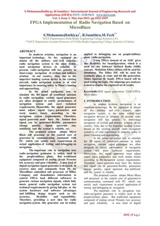
  • 1. S.MohammedInthiyaz, B.Sumithra / International Journal of Engineering Research and Applications (IJERA) ISSN: 2248-9622 www.ijera.com Vol. 3, Issue 3, May-Jun 2013, pp.1032-1039 1032 | P a g e FPGA Implementation of Radio Navigation Based on MicroBlaze S.MohammedInthiyaz* , B.Sumithra,M.Tech** *(ECE Department,G.Pulla Reddy Engineering College Kurnool,A.P,) **(ECE Department,Assistant Processor of G.Pulla Reddy Engineering College ,Kurnool,A.P,India) ABSTRACT In moderm aviation, navigation is an important technology. So far, equipped in almost all the military and civil airports, radio navigation system is the most widely used navigation devices in aviation. At present, radio navigation still has priority in short-range navigation of civilian and military aviation in our country. Also, due to the imperfect landing system device in the existing aircraft, radio navigation system is of vital importance in ensuring safety in Plane’s homing and approaching. In the actual navigation test, to simulate the RF signal of combined antenna in radio navigation, various signal generators are often designed to satisfy performance of navigation system and meet technical requirements. Meanwhile, the signal generator must adjust signal types, parameters and work modes timely according to the navigation system requirements. Therefore, signal generator must have the feature that signal can be generated flexibly, parameters change quickly, signal spectrum stay stabilized, and the system is reliable, etc. The proposed system adopts Micro Blaze soft processor as the control core of generator to communicating command with PC. which can satisfy each requirement in actual application of testing and debugging on navigation. The important role in navigation test, radio navigation generator is widely used in the people/military plane. But traditional equipment composed of analog circuit Presents low accuracy and poor reliability. A new kind of digital navigation signal generator is designed. It receives data and commands from PC by MicroBlaze embedded soft processor of Xilinx Company and demodulates information to control FPGA load different softwares to generate various navigation signals, which fully meets general radio navigation system test technical requirements by giving full play to the system hardware and software advantages and fulfilling design targets such as the accuracy, flexibility and expansibility. Therefore, providing a new idea for radio navigation system. this generator can be widely applied to debugging use on people/military plane radio navigation. Using FPGA instead of an ASIC gives also flexibility for reconfiguration, which is a need for the Software Defined Radio (SDR) concept. Modelsim Xilinx edition will be used for simulation. The Xilinx ISE will be used for synthesis; place & route and bit file generation. Xilnix Spartan 3E family FPGA board will be used testing the logic. The chipscope pro analyzer is used to display the captured set of results. Keywords-DDS signal generation, UART,FPGA, Micro blaze. 1. INTRODUCTION In modem aviation, navigation is an important technology. So far, equipped in almost all the military and civil airports, radio navigation system is the most widely used navigation devices in aviation. At present, radio navigation still has priority in short-range navigation of civilian and military aviation in our country. Also, due to the imperfect landing system device in the existing aircraft, radio navigation system is of vital importance in ensuring safety in plane‟s homing and approaching. In the actual navigation test, to simulate the RF signal of combined antenna in radio navigation, various signal generators are often designed to satisfy performance of navigation system and meet technical requirements. Meanwhile, the signal generator must adjust signal types, parameters and work modes timely according to the navigation system requirements. Therefore, signal generator must have the feature that signal can be generated flexibly, parameters change quickly, signal spectrum stay stabilized, and the system is reliable. The proposed system adopts Micro Blaze soft processor as the control core of generator to communicating command with PC. which can satisfy each requirement in actual application of testing and debugging on navigation. The important role in navigation test, radio navigation generator is widely used in the people/military plane. But traditional equipment composed of analog circuit Presents low accuracy and poor reliability. A new kind of digital
  • 2. S.MohammedInthiyaz, B.Sumithra / International Journal of Engineering Research and Applications (IJERA) ISSN: 2248-9622 www.ijera.com Vol. 3, Issue 3, May-Jun 2013, pp.1032-1039 1033 | P a g e navigation signal generator is designed. It receives data and commands from PC by MicroBlaze embedded soft processor of Xilinx company and demodulates information to control FPGA load different softwares to generate various navigation signals, which fully meets general radio navigation system test technical requirements by giving full play to the system hardware and software advantages and fulfilling design targets such as the accuracy, flexibility and expansibility. Therefore, providing a new idea for radio navigation system. this generator can be widely applied to debugging use on people/military plane radio navigation. 2.BLOCK DIAGRAM OF IMPLEMENTING MODULES Fig.1: Processing modules of FPGA 2.1 DESIGN SCHEME OF DIGITAL SIGNAL GENERATOROFRADIO NAVIGATION According to different technical requirements of navigation, the generated signal is basically formed by the carrier signal, low frequency modulated signal and audio modulated signal. Therefore, in this scheme, the signal generator adopts direct digital frequency synthesizer (DDS) technology to design precise clock reference source, word length of frequency and phase accumulator and sine function table to generate the modulated sine signal whose frequency variation scope, step length change and precision meet the acquirements in overall design. Large-scaled FPGA is used in this system to realize accurate DDS , ADC converter is used to convert the external signal to be modulated by carrier signal, and the soft embedded processor MicroBlaze communicates with PC by RS422/232 as the control core, figure is the overall scheme of digital signal generator of radio navigation. The control software of PC wrote in VC6.0 communicates with the generator through RS422/232 is in charge of transmitting control command to set frequency, azimuth angle, channel, working mode and other parameters of navigation signal and receiving status and data of the generator after every change. In this system, as a master unit MicroBlaze sends parameters to FPGA after demodulating data from PC while FPGA generates accurate navigation signal to high-speed DAC converter as the ground floor synthesis unit. Meanwhile, multiple clock signals used in the system are generated in phase lock logic part of FPGA from external oscillator. 2.2 DIRECT DIGITAL SYTHESIZER Fig.2 Playing an important role in navigation test, radio navigation generator is widely used in the people/military plane. But traditional equipment composed of analog circuit presents low accuracy and poor reliability. A new kind of digital navigation signal generator is designed in this paper. It receives data and commands from PC by MicroBlaze embedded soft processor of Xilinx company and demodulates information to control FPGA load different softwares to generate various navigation signals, which fully meets general radio navigation system test technical requirements by giving full play to the system hardware and software advantages and fulfilling design targets such as the accuracy, flexibility and expansibility. Therefore, providing a new idea for radio navigation system design and test, this generator can be widely applied to debugging use on people/military plane radio navigation. A Direct Digital frequency Synthesizer (DDS) design and prototype suitable for space- borne applications is presented. The design is targeted for use in the uplink section of the RF subsystem of the New Horizons Pluto spacecraft currently under design at APL. Design and analysis of the digital portion of the DDS is presented along with experimental data from the prototype system, which was implemented using an FPGA and a discrete digital to analog converter. Direct Digital frequency Synthesizers (DDS) are a common component in a variety of communication systems, especially those requiring fast frequency hopping, low power dissipation, and small form factor. A DDS at its simplest is a clock-dividing counter, termed the phase accumulator, which generates a digitized ramp waveform. This ramp is converted to a sine-wave representation and subsequently translated to the analog domain by a digital to analog converter (DAC). Subsequent filtering of the DAC output can be used to remove the high frequency components that arise from the data conversion process. Fig. illustrates the
  • 3. S.MohammedInthiyaz, B.Sumithra / International Journal of Engineering Research and Applications (IJERA) ISSN: 2248-9622 www.ijera.com Vol. 3, Issue 3, May-Jun 2013, pp.1032-1039 1034 | P a g e conceptual system with a j-bit accumulator output truncated to a k-bit ROM address space and a m-bit DAC.DDS performance is measured in a number of ways. Some are fairly generic, including power dissipation and maximum nput clock rate and output frequency. Others are more specific, relating to minimum frequency step size and to the spectral purity of the DDS output. The DDS output spectrum reflects the fact that a DDS effectively samples a sine wave output. As a result, inaccuracies due to finite word length effects as well as Nyquist sampling considerations cause the output spectrum to contain energy at frequencies other than the fundamental. These peaks, termed spurs, determine the signal to noise level of the DDS, which is defined as the Spurious Free Dynamic Range (SFDR). Non-idealities in the DAC can further degrade the SFDR as well. In general, peaks which are closer in frequency to the fundamental presentmore problems than peaks further out, simply because they are more difficult to attenuate with an output low pass filter. 2.3 IMPLEMENTATION OF DDS In this project we are using Direct Digital Synthesizer for generation of the carrier signal. All we know about that by using DDS we can generate a carrier signal in the form of sine or cosine or sinecosine.Xilinx itself generate the core for DDS that is ip core generation. In that we should select options about the carrier or signal frequency in MHZ and phase off set and data width and the phase increment register data width depends on the data width or we can have a option like programmable then we can give the phase of set and frequency levels through the program. And we are taking the carrier signal from the DDS and we do the modulation like AM,FM,QPSK,BPSK.And in FM technique we are taking DDS signal as the message signal and we are generating the carrier by using the Hardware Description Language. The Analog to Digital Module Converter Board (the AD1™) converts signals at a maximum sampling rate of one million samples per second, fast enough for the most demanding audio applications. The AD1 uses a 6-pin header connector, and at less than one square inch is small enough to be located at the signal source.The AD1 converts an analog input signal ranging from 0-3.3 volts to a 12-bit digital value in the range 0 to 4095. The AD1 has two simultaneous A/D conversion channels, each with a 12-bit converter and filter. Each channel can sample a separate stream of analog signals. The AD1 can also convert a single stream of analog signals using only one channel. Each channel has two 2-pole Sallen-Key antialias filters with poles set to 500 KHz. The filters limit the analog signal bandwidth to a frequency range suitable to the sample rate of the converter. The AD1 uses the SPI/MICROWIRE™ serial bus standard to send converted data to the host system. The serial bus can run at up to 20 MHz. The AD1 has a 6-pin header and a 6-pin connector for easy connection to a Digilent system board or other Digilent products. Some system boards, like the Digilent Pegasus board, have a 6-pin header that can connect to the AD1 with a 6-pin cable. To connect the AD1 to other Digilent system boards, a Digilent Modular Interface Board (MIB) and a 6-pin cable may be needed. The MIB plugs into the system board, and the cable connects the MIB to the AD1. The AD1 can be powered by voltage from either a Digilent system board or an outside device. Damage can result if power is supplied from both sources or if the outside device supplies more than 3V.Rst is used to reset module or clear previous data, clk is used for the synchronization, when the raising edge of clk is „1‟ then count is a counter, go on counting from „0‟ to „15‟ if count is „0‟ then data present in shift resisters (signal‟s) will be forced on to the output‟s pdata1, if count is above „3‟ then inputs will be forced on to shift register‟s (signal‟s) from LSB to MSB till the count „15‟ by shifting 1 bit for each count. CS will „1‟ for the count of “15”. Pclk will be „1‟ for 0 to 8 counts and „0‟ for the rest of count‟s i.e it is clk /16 As we know that the analog to digital converter is used to convert the analog signal into the digital samples. And we are using the 12 bit A/D converter means at the ADC output we get the 12 bit sample values of the analog signal. Here we are giving a message signal (Modulating signal) through ADC. It is 2-channel ADC means we can give 2 inputs at a time and here we are connecting the input to the ADC from the Function Generator by giving the frequency levels and selecting a wave(sine or sawtooth,Square..etc) and constant voltage levels 3. BLOCK DIAGRAM OF UART The UART block diagram for the fpga implementation is shown in Fig. It consists of 4 blocks namely transmitter, receiver, enable generator and baud generator. The uart transmitter and receiver are deigned in the same block which is shown in below. The UART is a serial interface with a frame format of start bit of active low „0‟at the beginning and 8 bit of information with a stop bit of active high„1‟ signal at the end. The operation of UART is controlled by Clock signal which is fed from external crystal.Baud generation section is a clock divider ckt, FPGA board clock runs at 50MHz, but UART transfer data at predefined standards that hade to be maintained, in present system is designed for a rate of 9600/sec(i.e 50x106 is scaled down for 9600). Generates a 9600 pluses for a sec, this implies the speed of UART is 9600 bits per sec. another clock with a 16 times faster is required to the receiver section so that the data will not be corrupted, baud out is given to the enable generator section.Enable Generator this section
  • 4. S.MohammedInthiyaz, B.Sumithra / International Journal of Engineering Research and Applications (IJERA) ISSN: 2248-9622 www.ijera.com Vol. 3, Issue 3, May-Jun 2013, pp.1032-1039 1035 | P a g e receives baud_clock signal as a enable signal and gives enable out signal to the transmitter section as a enable input signal.This signal is used to synchronize the transmitter section when ever the data is to transferred. The transmitter block is responsible for the transmission of serial data from UART. It takes 8-bit data from the receiver section in parallel andsend data in serial form. Data inserted between start and stop bits. An optional parity bit also may be usedfor error detection. state machine for transmitter is shown in Fig. Fig.3 Transmitter stays in IDLE state unless transmit enable (tx_enable) is made as „1‟.The data transmission starts with tx_enable = 1. As mandated by the protocol, a „0‟ is transmitted to indicate start of transmission or start bit. This is done in START state. Then data bits 0 to 7 are transmitted in states DATA0 to DATA7. If parity is enabled in configuration register, the data is attached with parity in PARITY state. Then transmitter enters STOP state and sends a „1‟. This indicates the completion of transmission. Then the transmitter enters the IDLE state and waits for next data transmission.UART receiver handles reception of data from RS232 port. main functions of receiver block are to convert the serial data to parallel data, check the correctness of data from parity and store the received data.UART receiver state machine is shown in Fig. The receiver is in IDLE state by default. When the serial data pin goes low, indicating the start bit, the state machine enters DATA0 state. The data is received, one bit at a time from LSB to MSB in states DATA0 to DATA7. If parity is enabled, the state machine checks the parity bit received against the parity obtained from received data. If the data received is fine, the data_rx (data_rx_done) bit is set to „1‟ and the receiver goes back to IDLE state again.top module is a combination of uart and a selected image processing applications. Type of operation is selected by slider switches on the FPGA board each and every block is explained in detail below. 4. REALIZATION OF DIGITAL SIGNAL GENERATOR OF RADIO NAVIGATION BASED ON MICROBLAZE 4.1HARDWARE PLATFORM: Xilinx XC2VlOOO of Virtex - II platform is adopted in this system which has 40 dedicated multiplier blocks, up to 93,184 look-up tables(LUTs) or cascadable l6-bit shift registers, 3 Mb of dual-port RAM in 18 kbit block SelectRAM resources and up to l.5 Mb of distributed SelectRAM resources and clocks up to 420MHz internal, presenting a strong computing ability and high speed data throughput capacity[9]. Also an in- system programmable configuration PROM XCF04SV020C is used for FPGA configuration in this system. The MicroBlaze embedded processor soft core is a reduced instruction set computer (RISC) optimized for implementation in Xilinx FPGAs. It is highly configurable, allowing users to select a specific set of functionality required by designs to build their own hardware platform [10]. Fast Simplex Link (FSL) bus is a uni-directional pointto- point channel bus used to perform fast communication between any two design elements on the FPGA when implementing an interface to the FSL bus. First create a hardware system whose core is MicroBlaze under the integrated environment of XPS using Base System Builder (BSB) wizard, then follow the guide of EDK to add a peripheral of system with UART IP core connected by MicroBlaze F SL bus, use the Platform Generator to generate embedded system's netlist document (.NGC) based on Microprocessor Hardware Specification (.MHS), and finally use the synthesized tool XST to constitute the whole hardware platform of the system [11 ]-[12]. ADC converter is mainly used for acquiring external low frequency signal. AD9218 with dual lO-bit channels of ADI company is selected in this system which works under 2.7V�3.6V and operates up to 105MSPS conversion rate [13]. DAC converter is mainly used for generating rf modulated signal. AD9760 with single lO-bit channel of ADI company supporting update rates up to l25MSPS is chosen in this system, whose single supply ranges from 2.7V to 5.5V. Design of PC Software Main task of PC software is to generate control command for frequency, azimuth angle, work mode, channel selection andother information which can be distinguished by command head and transmitted by RS422/232 to signal generator for the corresponding digital navigation signal. 2.2.2 Design of FPGA processing modules Main task of FPGA hardware is to produce precise modulatedrf modulated signal. The tasks are included as follows: 1) receiving
  • 5. S.MohammedInthiyaz, B.Sumithra / International Journal of Engineering Research and Applications (IJERA) ISSN: 2248-9622 www.ijera.com Vol. 3, Issue 3, May-Jun 2013, pp.1032-1039 1036 | P a g e carrier frequency, azimuth angle and other Relevant control commands from MicroBlaze; 2) generating audio signal, carrier signal andazimuth angle signal; 3) receiving two channel low frequency signal from ADC converter; 4) synthesizing navigation signal and transmitting it to DAC converter according to the command from PC. T he processing modules of FPGA is shown in figure. Design of MicroBlaze processing First define software systems using Microprocessor Software Specification (.MSS) readable text files which describe driver information of all peripherals. Once the system software is defined, use the Library Generator to build system- specific library C functions that map basic C functions to peripherals and to configure the C libraries. Then write the corresponding receiving program code to 380 achieve MicroBlaze control function using the function libraries in SDK integrated environment. In the end, package the hardware structure and application software of UART controller based on MicroBlaze into ISE as a sub-module and complete software design of MicroBlaze controller. The software process flow is shown in figure. 4.2IMPLEMENTATION OF MICROBLAZE In our project the Microblaze place a main important role. It is a soft core processor. and we know about the two type processors, those are Micrblaze and the Power Pc. The main difference between the microblaze and power pc is ,microblaze is a soft core processor and the power pc is a hard core processor. Microblaze: Which is a soft core processor, the some part of the fpga will acts as a microblaze processor by implementing the hardware description language means by the vhdl code we are making act of some part of fpga as microblaze. So it is called as soft core processor. No need of any external hardware circuitry. Power Pc: It is hard core processor, means it is different than microblaze. In this we should require the external hardware by connecting this external hardware of the power pc to the fpga we can use the processor. Then the circuit complexity may increase. So in this project we are implementing Microblaze soft core processor only. And this processor will take the information from the Pc by using UART. So from the we receive the commands in hexa,ascii format. By using these commands only we can change our parameters of modulation techniques like setting frequency ,setting azimuth angle, changing work mode, self testing and output RF signal. This function we will implementing by coding. Acoording to these commands the modulation techniques are select in the synthesized unit. 5. NUMERICAL TEST AND SIMULATION Due to the diversity of technique requirement ofnavigation signal, the main task of generator is to generatedifferent kinds of rf modulated signal. Take AutomaticDirection Finder (ADF) signal for example, it is in form ofV =E{m+Mcos(Qt+8)+v:,}cosC/{tE is the signal amplitude, m is a constant, M ismodulation index, Q is frequency of low frequencymodulated signal, e is the azimuth angle, Va is the audiomodulated signal and We is the carrier frequency [1].Assume E=�m=�M=o.3,Q=2.7zx<X),e=o,cq =2m<l'XYc,the frequency of audio signal is 1020Hz and the samplefrequency is 40MHz and simulate the ADF signal inMA TLLAB software, the result is shown in Fig.Take another signal for example, the signal of Very highfrequencyOmnidirectional Range (VOR) can be expressedasV =URm [1 +mA cos(Qt- e) +mcos( n.t+mfcosQt) JcosatU Rm is the amplitude of reference phase signal, e is theazimuth angle , Q is the angular frequency at 30Hz, Qs isthe angular frequency at 9960Hz, m A is the modified factorof variable phase signals, m f is the modulation index, m ismodulation of reference phase signal and W is the angularfrequency of carrier signal. [1 ]Due to that the frequency of VOR signal is too high andthe hardware is limited in performance, we assume URm = 1,m = 1 m = 03 m = 1 e = 60 w = 271x20M , the sample A' . ' f ' 'cfrequency is 40MHz, VOR signal is simulated inMATLLAB software and the result is shown in Fig..Use the PC software to control the system to generate theADF signal in the same condition with the MA TLABsimulation and connect the generated ADF signal to theoscillator. The real ADF signal waveform is shown in Fig.which is almost the same with the simulated signal in Fig..Then connect the real ADF signal to the spectrum analyzer,the minimum resolution of the signal is up to O.OlHz.Similarly, generate the VOR signal in the same conditionof simulation in MA TLAB and connect it to the oscillator.The real VOR signal waveform is shown is Fig. which isalmost the same with the simulated signal in Fig.. Thenconnect the real VOR signal to the frequency analyzer, theminimum resolution of the real signal is up to O.OlHz.
  • 6. S.MohammedInthiyaz, B.Sumithra / International Journal of Engineering Research and Applications (IJERA) ISSN: 2248-9622 www.ijera.com Vol. 3, Issue 3, May-Jun 2013, pp.1032-1039 1037 | P a g e 6. FINAL SIMULATION RESULTS Fig.4.A.M Fig.5.F.M
  • 7. S.MohammedInthiyaz, B.Sumithra / International Journal of Engineering Research and Applications (IJERA) ISSN: 2248-9622 www.ijera.com Vol. 3, Issue 3, May-Jun 2013, pp.1032-1039 1038 | P a g e Fig.6.QPSK 7. APPLICATIONS  Aviation, navigation and other equipment.  Software defined radios for military applications. 8. ADVANTAGES  Full digital techniques can give room for full reconfigurability of the MODEM for different specifications.  DDS based carrier synthesis has no limitation for tracking the signal of even wideband signal.  FPGA based implantation will result in extremely high speed and also can provide room for adding additional hardware blocks. 9. TOOLS AND HARDWARE  Simulation software - Modelsim Xilinx Edition (MXE)  Synthesis, P&R - Xilinx ISE  On chip verificaiton- Xilinx Chipscope  Hardware - Xilinx Spartan 3 Family FPGA board 10. CONCLUSION In this paper, the digital signal generator of radio navigation is implemented by soft processor MicroBlaze whose key portion is achieved in a single FPGA chip, which overcomes the disadvantage of low accuracy and flat tuning in traditional methods. Simultaneously, various kinds of signals can be loaded in this system, obtaining more flexibility and better expandability. Through the numerical test and simulation results, the veracity and precision is confirmed. Favorable result has been acquired in practical application. REFERENCES [1] M.Cunbao, Z.Tianwei and L.Hongjuan, "Communication Navigation and Radar of Civil Aircrft," Civil Avitation Engineering College, NPU, 2000. [2] X.Song, "Reasearch on software radio compass technology," University of Electronic Science and Technology of China, 2007. [3] L.QIN, D.Liebo and W.Peng, "Design of Simulative Satellite Image Resource System Based on FPGA," Journal of Test and Measurement Technology, vol. 23, Mar.2009, pp. 261-265, doi: CNKI: SUN: CSJS.0.2009-03-015. [4] Z.Mingjie, G.Wei, "Design of GPS IF signal generator in FPGA," Information Technology, NO.8, Aug.2008, pp. 56-58, doi: CNKI: SUN:HDZJ.0.2008-08-021. F1'GA XilUlX V2 Interface of power
  • 8. S.MohammedInthiyaz, B.Sumithra / International Journal of Engineering Research and Applications (IJERA) ISSN: 2248-9622 www.ijera.com Vol. 3, Issue 3, May-Jun 2013, pp.1032-1039 1039 | P a g e Cache CacheLblJ Indicator Rf signal Output PC . [5] L.Xiaoming and Q.xiujie, "Application of DDSIFPGA in Signal Generator Systems," Modem Electronics Technique, vol. 29, Sep.2006, NO.9, pp.78-79, doi: CNKI:ISSN:I004-373X.0.2006-09- 027. [6] Y. Yong and Z.xiaolin, "Design and Implementation of Direct Digital Frequency Synthesis Sine Wave Generator Based on FPGA," Journal of Electron Devices, vo1.28, NO.1, Mar.2005, pp: 596-599, doi:cnki:ISSN: 1 00 5-9490 .0.200 5-03-034. [7] A.Grama and G.Muntean. "Direct digital frequency synthesis implemented on a FPGA chip," the 29th International Spring Seminar on Electronics Technology: Nano Technologies for Electronics Packaging, May.2006, pp. 92-97, doi: 10.1109/ISSE.2006.365365. [8] D.J.Betowski and V.Beiu, Considerations for phase accumulator design for Direct Digital Frequency Synthesizers, IEEE International Conference on Neural Networks and Signal Processing, Dec.2003, pp: 176-179, doi: 10.ll09/ICNNSP.2003.1279240.