Total Harmonic Distortion Alleviation by using Shunt Active Filter
Ch32524527
1. Mr. Sarang A. Khadtare, Mrs. B.S. Dani / International Journal of Engineering Research and
Applications (IJERA) ISSN: 2248-9622 www.ijera.com
Vol. 3, Issue 2, March -April 2013, pp.524-527
Study of Three Phase Cascaded H-Bridge Multilevel Inverter For
Asymmetrical Configuration
Mr. Sarang A. Khadtare*, Mrs. B.S. Dani**
*(Department of Electrical Engg., Nagpur University, India.
** (Department of Electrical Engg, Nagpur University, India.
ABSTRACT
We know that, the inverters are broadly waveform.
classified as two level inverters and multilevel
inverters. This conventional inverters have
many limitations at high power and high voltage
applications. However, the multilevel inverter
becomes popular for high power and high
voltage applications due to their increased
number of levels at the output. As number of
levels increases, the harmonics are reduced and
output voltage tend to become more pure i.e.,
sinusoidal. There are three types of topologies
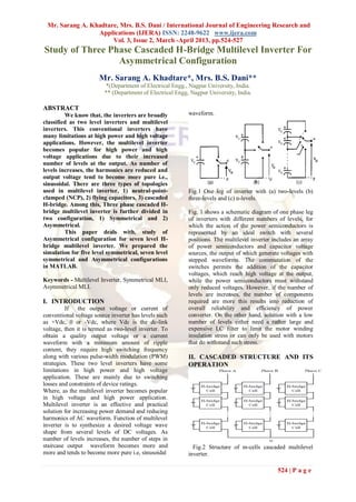
used in multilevel inverter, 1) neutral-point- Fig.1 One leg of inverter with (a) two-levels (b)
clamped (NCP), 2) flying capacitors, 3) cascaded three-levels and (c) n-levels.
H-bridge. Among this, Three phase cascaded H-
bridge multilevel inverter is further divided in Fig. 1 shows a schematic diagram of one phase leg
two configuration, 1) Symmetrical and 2) of inverters with different numbers of levels, for
Asymmetrical. which the action of the power semiconductors is
This paper deals with, study of represented by an ideal switch with several
Asymmetrical configuration for seven level H- positions. The multilevel inverter includes an array
bridge multilevel inverter. We prepared the of power semiconductors and capacitor voltage
simulation for five level symmetrical, seven level sources, the output of which generate voltages with
symmetrical and Asymmetrical configurations stepped waveforms. The commutation of the
in MATLAB. switches permits the addition of the capacitor
voltages, which reach high voltage at the output,
Keywords - Multilevel Inverter, Symmetrical MLI, while the power semiconductors must withstand
Asymmetrical MLI. only reduced voltages. However, if the number of
levels are increases, the number of components
I. INTRODUCTION required are more this results into reduction of
If the output voltage or current of overall reliability and efficiency of power
conventional voltage source inverter has levels such converter. On the other hand, solution with a low
as +Vdc, 0 or -Vdc, where Vdc is the dc-link number of levels either need a rather large and
voltage, then it is termed as two-level inverter. To expensive LC filter to limit the motor winding
obtain a quality output voltage or a current insulation stress or can only be used with motors
waveform with a minimum amount of ripple that do withstand such stress.
content, they require high switching frequency
along with various pulse-width modulation (PWM) II. CASCADED STRUCTURE AND ITS
strategies. These two level inverters have some OPERATION
limitations in high power and high voltage
application. These are mainly due to switching
losses and constraints of device ratings.
Where, as the multilevel inverter becomes popular
in high voltage and high power application.
Multilevel inverter is an effective and practical
solution for increasing power demand and reducing
harmonics of AC waveform. Function of multilevel
inverter is to synthesize a desired voltage wave
shape from several levels of DC voltages. As
number of levels increases, the number of steps in
staircase output waveform becomes more and Fig.2 Structure of m-cells cascaded multilevel
more and tends to become more pure i.e, sinusoidal inverter.
524 | P a g e
2. Mr. Sarang A. Khadtare, Mrs. B.S. Dani / International Journal of Engineering Research and
Applications (IJERA) ISSN: 2248-9622 www.ijera.com
Vol. 3, Issue 2, March -April 2013, pp.524-527
The Fig.2 shows, structure of m-cells cascaded To provide a large number of output levels without
multilevel inverter. In which, each phase consists of increasing the number of inverters, asymmetric
H-bridge cell connected in series with other H- multilevel inverters can be used. It is proposed to
bridge cell. Same is true for all three phases. Such a chose the dc-voltages sources according to a
structure is known as cascade ding. The structure of geometric progression with a factor of 2 or 3. For N
single H-bridge cell is shown in Fig.3. of such cascade inverters, one can achieve the
following distinct voltage levels,
Table 1. Comparison of Multilevel Inverter
Symmetri Asymmetrical inverter
cal
Binary Ternary
inverter
N 2N+1
DC sources
N N N
number
Switch number 4N 4N 4N
Fig.3 H-bridge cell structure.
N
As shown in fig., the four IGBT's are
arranged in bridge fashion in order to form single
phase H-bridge. Which is supplied by an isolated The maximum output voltage of these N cascaded
dc source on dc side, which can be obtained from multilevel inverters is,
batteries, fuel cell, or ultracapacitors. The Vo,MAX = (6)
advantage of this topology is that the modulation,
Equation (6) can be rewritten as,
control, and protection requirements of each bridge
are modular. It should be pointed out that, unlike
the diode-clamped and flying-capacitor topologies,
isolated dc sources are required for each cell in (7)
each phase.
In symmetrical multilevel inverter, all H-
bridge cells are fed by equal voltages, and hence all
the arm cells produce similar output voltage steps. Comparing (3) to (7), it can be seen that
However, if all the cells are not fed by equal asymmetrical multilevel inverters can generate
voltages, the inverter becomes an asymmetrical more voltage levels and higher maximum output
one. In this inverter, the arm cells have different voltage with the same number of bridges.
effect on the output voltage. An output phase-
voltage waveform is obtained by summing the
bridges output voltages,
vo (t) = vo,1 (t) + vo,2 (t) + · · · + vo,N (t)
(1)
where, N is the number of cascaded bridges.
The inverter output voltage vo (t) may be
determined from the individual cells switching
states,
vo (t) = μj = 0,
1, . . . . (2)
If all dc-voltage sources in Fig. 1 are equal to Vdc,
the inverter is then known as a symmetric
multilevel one. The effective number of output
voltage levels n in symmetric multilevel inverter is
Fig.4 Block diagram of five level inverter.
related to the cells number by,
n = 1+2 N (3)
As shown in fig.4, if the each upper H-
The maximum output voltage Vo,Max is then
bridge cell in each phase is supplied by 2Vdc and if
Vo,MAX = NVdc. (4)
each lower H-bridge cell in each phase is supplied
by Vdc then we are able to obtained the same value
525 | P a g e
3. Mr. Sarang A. Khadtare, Mrs. B.S. Dani / International Journal of Engineering Research and
Applications (IJERA) ISSN: 2248-9622 www.ijera.com
Vol. 3, Issue 2, March -April 2013, pp.524-527
of output voltage but with seven levels. Similarly,
if the each upper H- bridge cell in each phase is 300
supplied by 3Vdc and if each lower H-bridge cell in
each phase is supplied by Vdc then we are able to
obtained the same value of output voltage but with 200
nine levels.
Phase Voltage (Volts)
III. RESULTS 100
300 0
200 -100
Phase Voltage(Volts)
100 -200
0 -300
0 0.16 0.33 0.49 0.66 0.83 1
Time(Sec)
-100
(A)
-200
600
-300 400
0 0.16 0.33 0.49 0.66 0.83 1
Time(Sec)
Line Voltage (Volts)
(A) 200
600
0
400
-200
Line Voltage(Volts)
200
-400
0
-600
0 0.16 0.33 0.49 0.66 0.83 1
-200 Time (Sec)
(B)
-400 Fig.6 Simulation Results For 7- Level Symmetric
Cascaded H-Bridge Multilevel Inverter, A) Phase
Voltage; B) Line Voltage.
-600
0 0.16 0.33 0.49 0.66 0.83 1
Time(Sec)
(B)
Fig.5 Simulation Results For 5- Level Symmetric
Cascaded H-Bridge Multilevel Inverter, A) Phase
Voltage; B) Line Voltage.
526 | P a g e
4. Mr. Sarang A. Khadtare, Mrs. B.S. Dani / International Journal of Engineering Research and
Applications (IJERA) ISSN: 2248-9622 www.ijera.com
Vol. 3, Issue 2, March -April 2013, pp.524-527
REFERENCES
300 [1] ''Power Electronics'' Circuits, Devices,
And Applications, 3rd Edition by
Muhammad H. Rashid.
200 [2] Bipin Singh, KP Singh and AN Tiwari,
''Modelling of 5-Level Inverter
Phase Voltage (Volts)
Controlled With DVR Technique'',
100 VSRD-IJEECE, Vol. 2 (1), 2012, 16-21.
[3] F. Khoucha, M. S Lagoun, K. Marouani,
A. Kheloui, and M.E.H. Benbouzid,
0 “Hybrid cascaded H-bridge multilevel
inverter induction motor drive direct
torque control for automotive
-100
applications,” IEEE Trans. Ind. Electron.,
vol. 57, no.3,pp.892–899, Mar. 2010.
-200 [4] Farid Khoucha, Mouna Soumia Lagoun,
Abdelaziz Kheloui, and Mohamed El
Hachemi Benbouzid, Senior Member, "A
-300 Comparison of Symmetrical and
0 0.16 0.33 0.49 0.66 0.83 1 Asymmetrical Three-Phase H-Bridge
Time(Sec) Multilevel Inverter for DTC Induction
Motor Drives'', IEEE TRANSACTIONS
(A) ON ENERGY CONVERSION, VOL. 26,
NO. 1, MARCH 2011.
600 [5] K.Surya Suresh1 and M.Vishnu Prasad,
Sri Vasavi Institute of Engineering and
Technology, EEE Department,
400 Nandamuru, AP, India "PV Cell Based
Five Level Inverter Using Multicarrier
PWM" International Journal of Modern
Line Voltage (Volts)
200 Engineering Research (IJMER) Vol.1,
Issue.2, pp-545-551.
[6] Bindeshwar Singh, Nupur Mittal , Dr.
0 K.S. Verma , Dr. Deependra Singh,
S.P.Singh, Rahul Dixit, Manvendra Singh,
Aanchal Baranwa, "Multi-level inverter:
A literature survey on topologies and
-200 control strategies" International Journal
of Reviews in Computing 31st July 2012.
Vol. 10.
-400 [7] Jannu Ramu1, S.J.V. Prakash, K.Satya
Srinivasu1, R.N.D. Pattabhi Ram, M.
Vishnu Prasad and Md. Mazhar
-600 Hussain,''Comparison between
0 0.16 0.33 0.49 0.66 0.83 1 Symmetrical and Asymmetrical Single
Time (Sec) Phase Seven Level Cascade H-Bridge
(B) Multilevel Inverter with PWM
Fig.7 Simulation Results For 7- Level Asymmetric Topology." International Journal of
Cascaded H-Bridge Multilevel Inverter, A) Phase Multidisciplinary Sciences and
Voltage; B) Line Voltage. Engineering, Vol. 3, No. 4, April 2012.
IV. CONCLUSION
From above waveforms and table we
concluded that, the Asymmetrical inverter is able to
produce same value of output voltage but with
more number of levels thus the output voltage has
less harmonics and it is more pure than
Symmetrical one. The number of bridges and DC
sources, switching losses are also reduced in
asymmetric MLI as compared to symmetrical.
527 | P a g e