
Recommended
Recommended
More Related Content
What's hot
What's hot (18)
Viewers also liked
Similar to E033021025
Similar to E033021025 (20)
Recently uploaded
Recently uploaded (20)
E033021025
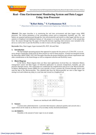
- 1. International Journal Of Computational Engineering Research (ijceronline.com) Vol. 3 Issue.3 21 ||Issn||2250-3005|| (Online) ||March||2013|| ||www.ijceronline.com|| Real –Time Envirnorment Monitoring System and Data Logger Using Arm Processor 1, B.Hari Babu, 2, Y.Varthamanan M.E 1,2, (Department of Electronics and Communication Engineering, Sathyabama University, India) Absract: This paper describes is to monitoring the real time environment and data logger using ARM processor. The various parameters of the surrounding system such as temperature, humidity, gas, fire and battery are acquired and processed through the Arm microcontroller and stored in a data logger and also we can analysis in Graphical Lcd.Additional features of this project is to locate the exact position of the sensed data from the sensors through Gps.The paper will describe decision regarding what resources were included in the device as well as how to provide flexibility in order to meet a diverse range of application. Keywords-:Bms, Data Logger, hyper terminal,LPG, POT, Sd card,Tdmi 1. Introduction We had multiple upcoming projects that appeared to require the low power of a 32-bit CPU, so we set out to design a board that would work for these projects as well as future projects. A board was designed around the Microchip ARM7TDMI LPC2148.This paper describes the project hardware and software requirements and other considerations in the board design as well as component selection and flexibility issues. 2. Block Diagram In the below, Block diagram there are three main applications involved they are: Industrial, Battery management system and Data logger. In Industrial application we measure (temperature, humidity, gas and pressure) through sensors. This sensed data are conditioned (by amplification) and given to the Microcontroller. In Battery Management System (BMS) for every periodic of time it monitor the (current) through sensors and send the data to the Microcontroller. This obtained data from the Microcontroller are sent to data logger for storing in sd card without any delay in a real time and viewed in a Graphical Lcd Sensors are interfaced with ARM Processor 3. Sensors A sensor (also called detector)is a converter that measures a physical quantity and converts into a signal which can be ready by an observer or by an (today mostly electronic)instrument. 3.1: HUMIDITY: Humidity is the amount of water vapor in an air sample.
- 2. Real –Time Envirnorment Monitoring System… 22 ||Issn||2250-3005|| (Online) ||March||2013|| ||www.ijceronline.com|| Circuit diagram of humidity sensor Circuit description: This circuit is designed to measure the humidity level in the atmosphere air. The humidity sensor is used for the measurement device. The humidity sensor is consists of astable mulitivibrator in which the capacitance is varied depends on the humidity level. So the multivibrator produces the varying pulse signal which is converted into corresponding voltage signal. The voltage signal is given to inverting input terminal of the comparator. The reference voltage is given to non inverting input terminal. The comparator is designed by the LM 741 operational amplifier. The comparator is compared with reference humidity level and delivered the corresponding error voltage at its output which is given to next stage of gain amplifier in which the variable resistor is connected in the feedback path by adjusting the resistor we can get the desired gain. Then the final voltage is given to microcontroller or other circuit in order to find the humidity level in the atmosphere. 3.2: Temperature: Temperature measurement using thermistor In this circuit the thermistor is used to measure the temperature. Thermistor is nothing but temperature sensitive resistor. There are two type of thermistor available such as positive temperature co-efficient and negative temperature co- efficient. Here we are using negative temperature co-efficient in which the resistance value is decreased when the temperature is increased. 3.3: Gas: Ideal sensor for use to detect the presence of a dangerous LPG leak in your car or in a service station, storage tank environment. This unit can be easily incorporated into an alarm unit, to sound an alarm or give a visual indication of the LPG concentration. The sensor has excellent sensitivity combined with a quick response time. The sensor can also sense iso-butane, propane. The unit will work with a simple drive circuit and offers excellent stability with long life. Circuit diagram of gas sensor
- 3. Real –Time Envirnorment Monitoring System… 23 ||Issn||2250-3005|| (Online) ||March||2013|| ||www.ijceronline.com|| Circuit description: This circuit is mainly designed to sense the present LPG GAS in the atmosphere. The LPG GAS (Propane) is sensed by the gas sensor. The gas sensor is the one type of transducer which produces the voltage signal depends on the gas level. Then the voltage signal is given to inverting input terminal of the comparator. The comparator is constructed by the operational amplifier LM 741. The reference voltage is given to non inverting input terminal. The comparator compares with normal reference signal and produces the corresponding output error signal. Then the output voltage is given to microcontroller in order to determine the presence of a dangerous LPG leak. 3.4: Fire: 3.4 .a: Flame sensor: The flame sensor is used to detect the flame occurrence. When the sensor detects the fire then it became short-circuit. When there is no fire the sensor become open circuit Circuit diagram of fire sensor Circuit description: The flame sensor is connected with resistor. This connection formed the voltage divider network which is connected with inverting input terminal of the comparator. The reference voltage is given to non inverting input terminal. The comparator is constructed with LM 741 operational amplifier. When there is no fire, the flame sensor became open circuit. So the inverting input terminal voltage is greater than non inverting input terminal (reference voltage). Now the comparator output is -12V which is given to the base of the switching transistor BC547. So the transistor is cutoff region. The 5v is given to 7404 IC. The 7404 is the hex inverter with buffer. Hence zero voltage is given to microcontroller. When there is fire occurred, the flame sensor became short circuit. So the inverting input terminal voltage is less than non inverting input terminal (reference voltage). Now the comparator output is +12V which is given to the base of the switching transistor BC547. So the transistor is turned ON. The zero voltage is given to 7404 IC. Hence +5v voltage is given to microcontroller. In the microcontroller we can detect the fire with the help of software. 4. Interfacing With Gps This is a third generation POT (Patch Antenna On Top) GPS module. This POT GPS receiver providing a solution that high position and speed accuracy performances as well as high sensitivity and tracking capabilities in urban conditions & provides standard NMEA0183 strings in “raw” mode for any microcontroller. The module provides current time, date, latitude, longitude, speed, altitude and travel direction / heading among other data, and can be used in a host of applications, including navigation, tracking systems, fleet management, mapping and robotics. This is a standalone GPS Module and requires no external components except power supply decoupling capacitors. It is built with internal RTC Back up battery. It can be directly connected to Microcontroller's USART. The module is having option for connecting external active antenna if necessary. The
- 4. Real –Time Envirnorment Monitoring System… 24 ||Issn||2250-3005|| (Online) ||March||2013|| ||www.ijceronline.com|| GPS chipsets inside the module are designed by MediaTek Inc., which is the world's leading digital media solution provider and largest fab-less IC company in Taiwan. The module can support up to 51 channels. The GPS solution enables small form factor devices. They deliver major advancements in GPS performances, accuracy, integration, computing power and flexibility. They are designed to simplify the embedded system integration process. 5. Interfacing with Graphical LCD This project is designed to interface graphical: CD to ARM based microcontroller. Data entry is through PC’s hyper terminal and the received data is displayed on graphical LCD. MAX 232 is used to communicate with the hyper terminal. The LPC2148 are based on a 16/32 bit ARM7TDMI-S™ CPU with real-time emulation and embedded trace support, together with 128/512 kilobytes (kB) of embedded high speed flash memory. A 128-bit wide memory interface and a unique accelerator architecture enable 32-bit code execution at maximum clock rate. For critical code size applications, the alternative 16-bit Thumb Mode reduces code by more than 30% with minimal performance penalty. With their compact 64 pin package, low power consumption, various 32-bit timers, 4- channel 10-bit ADC, USB PORT,PWM channels and 46 GPIO lines with up to 9 external interrupt pins these microcontrollers are particularly suitable for industrial control, medical systems, access control and point-of-sale. With a wide range of serial communications interfaces, they are also very well suited for communication gateways, protocol converters and embedded soft modems as well as many other general- purpose applications. 6. Flow Chart And Result Flow chart of the project
- 5. Real –Time Envirnorment Monitoring System… 25 ||Issn||2250-3005|| (Online) ||March||2013|| ||www.ijceronline.com|| 7. Conclusion The ARM7TDMI LPC2148 board has proven to be efficacious and robust in the above projects. Its flexibility to adapt to a wide range of Application. Future plans for this board include the all automated Management System described above as well as remote access and replacement of an embedded PC system controlling an industrial machine. 8. REFERENCES [1] Subramanian, R., Venhovens, PJ., Keane, B.P., "Accelerated Design and Optimization of Battery Management Systems using HIL Simulation and Rapid Control Prototyping", 2012 IEEE International Electric Vehicle Conference, March 4-8, 2012, Greenville, sc. [2] DU Chun-lei.ARM Architecture and Programming [M]. Beijing_Tsinghua university press,2003.(in Chinese) [3] Zhang Da-bo.priniciples,Design and application of embedded system[M].Beijing Machinery industry press_2004.(in Chinese) [4] Kyberd, Peter and Poulton, Adrian (2012). The use of multiple sensors in the control of prosthetic arms. In: Trent International Prosthetic Symposium TIPS 2012, 21-23 May 2012, Loughborough, UK. [3]