SlideShare ist ein Scribd-Unternehmen logo
1 von 13
Capacitors
WATER ANALOG
Imagine a system of water pipes as shown in Fig. 9.1, with a wide cylinder, and a movable piston
inside that. A spring tends to keep the piston near the middle. A rubber O-ring around it (shown
in cross section as two black dots) makes a fairly good seal, but the piston can still slide to the
right or left if water pushes it.
Fig. 9.1 A water analog of a capacitor.
Water coming into the cylinder will push the piston until the restoring force of the spring
becomes equal to the force from the water, and then all motion will stop. Therefore water that
moves toward the right, as shown in the diagram, will only be able to move for a short time. The
larger the size (the volume) of the cylinder, the more mass of water will be stored in it before it
stops, with constant pressure driving the system. Also, if the pressure is changed, but the size is
held constant, then the more water pressure, the more mass of water will be stored in the
piston/spring system before it stops "charging up." (This would be similar to
89
9. Capacitors
pumping air into a tire — the more volume and/or the more pressure, the more total mass of air
will be put in, until the inside pressure becomes equal to the pumping pressure, and then it will
stop.) Therefore, we could write an equation where
(mass moved in) = (size) (pressure) (9.1)
It is important to realize that water being pushed in just one direction (to the right, for
example) will eventually be stopped, whenever the cylinder pressure becomes equal and opposite
to the driving pressure (analogous to dc electricity). If the cylinder is small, this will happen
pretty fast. However, water that is only moving short distances back and forth will be able to
continue its "alternating" flow (analogous to ac electricity), whether the piston is in the pipe or
not, provided those motions are indeed very short. Longer motions could go back and forth, if
the cylinder is larger, although each motion will probably take a longer time before it reaches its
end point (analogous to ac electricity of low frequency).
These relationships are all close analogs to the behavior of electricity going into a capacitor,
where mass of water is like coulombs of electric charge, size of the cylinder is like
"capacitance," and pressure is like voltage. A bigger capacitor will allow longer-time back and
forth alternations of electricity.*
WHAT A CAPACITOR IS
A capacitor (called a "condenser" in older literature) consists of metal plates, sep-arated by a thin
layer of insulation, which could be vacuum or air, but usually is plastic or ceramic. When
attached to a battery, electrons will flow onto one metal plate, and they are pulled off the other
one, leaving positive charges there.
COMMENT
As the reader possibly knows, "electricity" in metal wires is entirely the flow of electrons, but
protons or nuclei do not move very far through metal. However, it is convenient for us to
imagine that either electrons are going in one direction or positive charges of some mysterious
kind are going in the opposite direction, although not both at the same time in the same place
(that would double the current). This is what the early scientific researchers believed, before
electrons were discovered, and it is still a useful idea, even though only the first half of it is
true. Sometimes the mathematical relationships in electronics, left over from the old days, are
still written in terms of positive charges moving. This is especially found in older books about
battery science, electroplating, and electric motors.
*
A small capacitor allows a small ac current. Thus the human body conduction on page 6.
9. Capacitors
When the charge accumulates on the metal plates of a capacitor (see top of Fig. 9.2), a
voltage appears, and this is equal to the total charge divided by the distance between the plates,
as previously described in the dimensions at the bottom of page 15. If there is just vacuum
between the plates, this situation is shown at the top of the figure. The meter is a high quality
multimeter, which can measure the capacitance directly. (The meters used in this course do not,
unless the instructor is able to obtain a special one for demonstrations.) It determines the
+ +
––
Fig. 9.2 Capacitors, with vacuum or ceramic between the plates.
amount of charge that flows into the capacitor when a certain voltage is applied from within the
meter. When the voltage on the capacitor builds up to be equal to the driving voltage coming
from the meter, the charging process stops. (Another useful analogy is to consider the capacitor
to be like a very small storage battery, which will stop charging when its voltage becomes equal
to the source voltage.)
An important observation is that more charge can be put on the capacitor, at a given voltage,
if the metal plates are closer together, as at the lower left side of Fig. 9.2. The reason for this
(which quite surprisingly is not usually taught in physics or electronics courses) is that repulsion
of the accumulated charges is what eventually stops further charges from coming onto the plates,
but the electric field (page 15) from the positive plate neutralizes some of the field on the
negative plate, and vice versa. This allows more charge to come in, before the flow finally stops.
The closer the plates are together, the more neutralization occurs, and the more additional charge
can come in.
9. Capacitors
Capacitance, C, is the amount of charge, Q,
per voltage, V, as in the following equation . Q
(in
coulombs) C(in farads) = ———————— (9.2)
V
(in volts)
Therefore, by rearranging the terms, Q = CV, similar to eqn. 9.1 on page 90.
Another useful relationship, somewhat difficult to find in most physics or electronics books,
is
(8.85 x 10⁻¹⁴
) (k') (Area)
C(in farads) = —————————— (9.3)
(Thickness of insulator). The area and thickness are in cm2
and
cm. The reader should note, from the 10-14
factor, that approximately one square centimeter of
plate size (if the insulator thickness is also a centimeter) gives only a tiny fraction of a "farad"
capacitance. Another way of saying this is that it would take about 1013
square centimeters of
plate size to give a whole farad. Therefore, it can be seen that a farad is a huge quantity of
capacitance.
Most practical-sized capacitors have values that are only in the range of microfarads, usually
referred to as "mfd." Sometimes the values are in picofarads ("pf," pronounced "puff," and
equivalent to 10-12
farad). It would be useful if the k' factor could somehow be made to be a large
number, to make up for the very
small 10-14
.
That k' factor is called the "relative dielectric constant," and it is dimensionless. If the
insulator (which is referred to as the "dielectric" in physics) is a vacuum, then k' = 1. Common
solid insulating materials like plastic or mica have k' values ranging from about 2 to 10.
Therefore, putting them in between the plates instead of a vacuum raises the capacitance. This is
shown at the lower right of Fig. 9.2, where the rectangle of solid dielectric allows more charge to
accumulate on the plates, just like putting the plates closer together would have done. It should
be noted that k' is the capacitance with a certain dielectric, divided by the capacitance with only a
vacuum between the plates, and that is the reason for the word "relative."
9. Capacitors
How does the dielectric material raise the capacitance? (Various other math is usually given
in textbooks and courses, but again, the reasons "why" are usually not explained.) All solid
materials consist of positively charged atomic nuclei, with electrons going around them in orbits.
In the strong electric field caused by the charged metal plates, the electrons of the dielectric tend
to "polarize," which means that they are attracted somewhat toward the positively charged plate
(toward the top, in the lower-right diagram of Fig. 9.2). The more they can move, the more they
polarize, and the higher their k' value is. In some materials they are more free than in others,
although they all stop after going a few Angstroms of distance, because they are insulators. (If
the charges continued to move, then these materials would be conductors, not insulators.) When
the electrons can spend more time than usual up near the positive plate, their positively-charged
nuclei (shown at the bottom of the rectangle in the figure) are exposed more to the negatively
charged bottom plate. These positive fields tend to neutralize the negative charges on that plate,
thus making less repulsion of new electrons, which can then move in. The more charges moving
in at a certain voltage, the more capacitance, according to equation 9.2. With some modern
dielectrics such as barium titanate or lead magnesium niobate ceramics,* the dielectric constant
raises the capacitance 1,000 or even 20,000 times greater than with vacuum.
Why not just make the spacing extremely small? Because the electricity can jump
spontaneously across very small gaps, making sparks. Thin materials such as mica that can be
put in between the plates and prevent sparks are said to have high "dielectric strength," which is
not the same as having a high dielectric constant. Instead, it means that a very high voltage can
be put across the insulator without causing "dielectric breakdown," in which a spark would
"punch through" the material. The goal of modern capacitor design is to make the insulator be as
thin as possible with a high dielectric strength, and also to have as high a dielectric constant as
possible. A great deal of progress has been made in this technology during the last few years.
(For examples, see pages 266 and 267.)
Some capacitors are made by separating two very long strips of aluminum foil by a very thin
sheet of plastic insulator. This sandwich is then rolled up into a convenient cylindrical shape,
having a fairly large area (see eqn. 9.3) and a fairly small thickness.
It should be intuitive that having a large area is equivalent to having many smaller-area
capacitors hooked up in parallel, and this is quite true. A practical
——————————
* Ceramics are made by sintering. More description is in the Glossary, page 274.
9. Capacitors
way to have many in parallel is to use the multilayer configuration of Fig. 9.3. The black lines
are metal layers, and insulating layers (not indicated specifically in the diagram) lie between
them. The more insulator layers (four in this diagram), the more capacitance. Up to 100 layers
are used in modern devices, also combined with ceramic dielectrics having high k' values.
Fig. 9.3 A multilayer device, where the capacitance is multiplied by four.
Just like pumping up a tire with compressed air, a capacitor will charge at the fastest "rate" in
the beginning, as shown at the left side of Fig. 9.4. The rate is the slope of the curve at any given
time point, and it is proportional to the current. As the capacitor voltage gets closer to the source
voltage, of course the difference gets vanishingly small, and it is that voltage difference that
drives the current. Therefore the current versus time curve (not shown) would look like the
"discharging" curve at the right — high in the beginning and low later on. Theoretically, the end
point would never quite be reached, but actually the current soon gets down into the random
"noise" level, where it can no longer be measured and is effectively zero. The mathematical
description is an "exponential" equation, similar to compound interest financial equations, or
radioactive decay equations. These equations would probably not be useful to readers of this
book,
so they are only described briefly in the
footnote.*
(The Greek letter is
explained
on the next
page.)
CHARGING DISCHARGING
V V
~ 2/3 Vmax
~ 1/3 V
t max
t
Tau Tau
Fig. 9.4 The voltage across a capacitor, versus time.
*
When charging, V = Vmax (1 – e – t/τ
). When discharging, V = Vmax (e – t/τ
). I = V / R.
9. Capacitors
During discharging at the right side of the figure, the time it would take to get to zero voltage
would be difficult to determine. Therefore, a more convenient discharging time is defined as the
time it takes for the voltage to get to about 1/3 of the original maximum value. The ~ ("tilde")
symbol means "approximately," and the exact fraction is 1/2.718, where the 2.718 is e, the base
of the natural logarithm. This calculates to be about 37%, which is very roughly 1/3. This
standard discharge time is usually called the time constant, and its symbol is the Greek letter τ
("tau").
During charging, the time to the full Vmax is theoretically infinite, as mention
ed on the previous page. However, the more convenient charging time is the time it takes to get
up to (1 – 0.37)Vmax , or about 63% of Vmax , and we can call that ~2/3 of the Vmax . Again, this
is called the time constant, τ.
A useful relationship is that the time constant is given by
τ = RC (9.4)
where R is whatever resistance is slowing down the charging or discharging, and τ is in seconds.
In Fig. 9.5, it looks like that R is about 2,500 ohms, both for charging and for discharging. If the
capacitance happens to be 1,000 mfd, that is the same as 0.001 farad. Then the time constant, τ,
for either charging or discharging is (2,500)(0.001) = 2.5 seconds.
EXPERIMENTS
Voltage Versus Time
The circuit of Fig. 9.5 should be constructed, where the "SPDT" switch is just a
9 Volts
9. Capacitors
clip lead, with only one end attached to the 5K pot, and other end not being clipped onto
anything. That loose end will later be touched to the battery's + terminal, and then later still, to
the – terminal or any wire attached to it, which will make it equivalent to a single pole, double
throw ("SPDT") switch. The term "double throw" means two possible positions, up and down as
shown here.
If it was a DPDT type (double pole, double throw), then there would be two switches hooked
together mechanically, so two movable parts would simultaneously make contact with two upper
terminals, or else with two lower terminals. Thus there would be 6 terminals altogether. At any
rate, we will use no real switch at all, just a loose clip lead.
Note the symbol for a capacitor, with a curved bottom line. Older literature used two straight
lines, such as the one shown in the lower left of Fig. 9.2. However, that is the same as the symbol
used by electricians to mean the contacts of a relay or switch, as will be discussed later in
Chapter 12. To prevent misunderstandings, electronics engineers have changed their capacitor
symbol to the one with a curved bottom. We will use a "polarized electrolytic" type with a
capacitance of 0.001 farad, which is unusually large. The white arrow on the case points to the
negative terminal, and the capacitor might be damaged if that wire is made positive for a long
time. (The insulator inside is a very thin layer of aluminum oxide on a rolled up strip of
aluminum foil. This oxide is generated electrolytically, and reversing the voltage could remove
it.)
Note also that if "leads" (wires coming out of a device such as a capacitor) have to be bent,
they should come out straight for a short distance and then only be bent at a place several
millimeters away from the device itself. On the other hand, if they are bent right at the edge of
the device, then the insulation around the device is likely to become damaged.
Adjusting the 5K pot (used here as a rheostat) to its highest resistance, and setting the
multimeter on the 15 volts dc range, touch (or actually clip) the loose clip lead to the battery. The
voltmeter will take a few seconds to reach the final 9 volt reading, following a curve like Fig.
9.4. Then touch the previously loose clip to a negative wire, and observe the discharge behavior.
Turn the pot to a lower resistance setting, but not all the way to zero. Go through the same
procedure and observe the faster time constant.
The reasons for not using the minimum resistance setting are that (1) too much current would
flow, possibly damaging the capacitor, and (2) all that current would go through a tiny area of
resistor material inside the pot, overheating and probably destroying it. If the circuit was using
that device as a true potentiometer, then during charging, the pot should not be set at the
maximum voltage, because too much current would pass through a small area.
9. Capacitors
Voltage Versus Current
Set up the circuit of Fig. 9.6, which is the same as the one on page 83, except that the capacitor
has been substituted instead of the light bulb. The arrow on the outside of the capacitor should
point to the ground, since that is negative. The scope settings can be the same as on page 84, but
the sensitivities can be changed somewhat if desired, because the voltages and currents do not
have to be so high this time. If the battery polarity is reversed (and the NORM / INV button is
pressed), then the capacitor leads can also be reversed, although using it the wrong way for a
short time will not really hurt it.
A curve similar to the one for the light bulb is observed, except that when the pot is turned
down again, a reverse current flows, while the capacitor ("cap") is discharging, and this did not
happen with the bulb. At any rate, the current changes (either increasing or decreasing) first,
while the cap is charging or discharging, and then the voltage changes a short time later. Going
up and down quickly with the pot makes a complete oval pattern on the scope screen.
SAFETY NOTE: Whenever anything is plugged into the 120 V ac wall socket, as it will be in
the next experiment, it would be best to have it go through a ground fault interrupter. Even the
small 12 V transformer could possibly have an internal short circuit from a primary wire to the
metal case, or to one of the
9. Capacitors
secondary wires. Although that seems unlikely, if thousands of people read this book and do
the experiments, it could happen to one person. If a GFI is not available, then the instructor
might use a neon tester, having one hand on one wire and touching the other wire (page 5) to
each 12 V transformer's metal case and secondary wire in the class, while the power cords
are plugged in. In addition, and more important, students should observe the one-hand rule
(page 4) when using 120 volts.
In this experiment, plug in the transformer and use its 12 V secondary instead of the battery.
With the X versus Y type of scope display, a continuous oval pattern is observed, which is called
a "Lissajous figure," named after an early scientist. The vertical VOLTS/DIV knobs, and also
their smaller VARIABLE knobs, can be adjusted to other settings such as >5V / div for X and
<20 mV / div for Y, in order to make the scope pattern become nearly a perfect circle.
Switching the MODE from CH2 to DUAL and TIME/DIV from X-Y to 20 ms will provide a
two-wave display, much like the right-hand side of Fig. 9.7. (Unplug the BNCs before the
transformer, to avoid an inductive kick.)
Phase (No experiments, except for the optional one on page 100)
Why does the voltage build up later than the current? The answer is possibly known to the
reader, but a lot of thought should be devoted to this point, since it is useful in many areas of
electronics. At the left of Fig. 9.7 is a pendulum, in
PENDULUM CAPACITOR
Fig. 9.7 "Out of phase" situations in a pendulum and a capacitor.
9. Capacitors
which the velocity is out of phase with (does not reach its maximum at the same time as) the
force that causes it. At first sight, one might expect that, at the very instant when the downward
force is greatest (at the position farthest to the right), the velocity should be greatest, and when
the gravitational force is zero, then the velocity should also be zero. However, that is not the
case, as indicated at the left-hand part of the figure. The reason why force and velocity are "out
of phase" is that one of them (velocity) is cumulative and must build up, increment by increment,
in order to reach its maximum value. The other one (force) is applied by gravity instantaneously.
(Note that it is dependent on the "resolution of forces," where the strength of the pendulum shaft
prevents any gravitational driving force at the very bottom of the swing). This is an easily
understood analog of things that happen in electronics, where one thing (not necessarily a
"driving force") is instantaneous, and another is cumulative, so their maxima occur at different
times.
The times are referred to as the "phases," and they are compared to the time it takes to
complete one whole cycle. In 60 Hz (60 cycles per second) ac electricity, one whole cycle takes
1/60 of a second, but another way of looking at it is to consider a cycle as if it was something
rotating, going 360 degrees from start to finish. (Actually, the electric generator that makes the
ac is really rotating.)
In a capacitor, since the voltage is cumulative, it is delayed, and the amount of delay is
referred to in terms of degrees instead of by fractions of a second. In this case, the delay (called
"lag" in electronics) is 90 degrees. Therefore we can say "the voltage and current are 90° out of
phase, and the voltage is lagging." Another way to say the same thing is "the current leads the
voltage by 90°." These relationships are quite important in motors, oscillators, etc.
OPTIONAL
Reactance
Since low frequency ac has difficulty going through a capacitor, there must be something
similar to resistance, which the capacitor presents to the electricity. This "something" is called
reactance. It does decrease the current flow, but it does other things also, and it can be
considered to be a sort of overall effectiveness of the capacitor. The "capacitive reactance" (to
distinguish it from "inductive reactance," which we will see later) is Xc in equation 9.5.
1 Xc = ————— (9.5) 2 π f
C
Pi is the usual 3.14, f is the frequency in Hz, and C is the capacitance in farads.
100 9. Capacitors
If an ordinary resistor is put in series with a capacitor, the situation might be as shown in
Fig. 9.8. Actually, there will always be some resistance (unless superconductors are used!),
including the small but often important resistance of the capacitor plates themselves, and
various solder joints and contacts.
An optional experiment that the reader might try is to put a 100 ohm resistor in series with
the 1,000 mfd capacitor and then do the experiment of Fig. 9.6 over again (but with 150 Ω
replacing the 100 Ω shown in the figure). The circular Lissajous figure without the resistor
becomes an oval, if 100 Ω is in series. When this resistance is not external but instead is inside
the capacitor (in the plates, etc.), it can be important in some applications. Even though it
might be a "distributed resistance" all throughout the device, one can imagine it to be a single
external resistor as in Fig. 9.8. In that case it is called "equivalent series resistance," or ESR. It
is part of the specification of high quality devices. The value of the ESR can be calculated from
the width of the Lissajous figure (page 98), if precisely calibrated equipment is used.
("Distributed capacitance" can also exist, when two insulated wires are close together, which is
often important at high frequencies.)
Another possible case would be resistance that might be in parallel, as shown by the
dashed lines in the diagram. It is not practical to measure this with the inexpensive equipment
being used in this laboratory course (although the reader is encouraged to try it as an optional
exercise), because the 1,000 mfd capacitor offers such a low resistance to 60 Hz ac that only a
negligible effect can be seen on the scope when a 100 ohm resistor is put in parallel.
(According to eqn. 9.5, this capacitor should have an effect similar to that of a 0.38 ohm
resistor.)
9. Capacitors 101
With a series resistance, the total resistance to ac will be more than that of
either device alone, and the effective value of this total is called impedance,
which is Z, as follows:
(9.6)
(A rule similar to Ohm's law still applies, so the current still is given by V / Z.) It is convenient
in electronics to use a type of vector for this relationship, called a "phasor," as in Fig. 9.8. Note
that the Z vector, the long-dash line, is the hypotenuse of the triangle made by the R and Xc
vectors (solid lines).
X = Reactance
Z = Impedance
Delta
Phase
R = Resistance
Fig. 9.9 "Phasors," which will be used in Chapter 16 (page 179).
The angle between Z and R is called the "phase angle," symbolized by the Greek letter φ
("phi"), and its value is 45° in Fig. 9.7, but it can be adjusted by changing R. For a pure
capacitance having zero series resistance, the phase is 90°, but for a pure resistance it is zero. The
other angle, 90° – φ , is called δ ("delta"). Note that the R / X is the tangent of delta, and in fact
it is referred to quite often in discussions about capacitors. Synonyms used in specifications
("specs") include:
R / X = "tanδ "= "loss" = "dissipation factor."
Loss can be calculated from the width and length of the Lissajous figure. Dielectric heaters
involve lossy capacitance (see also the middle of page 212).
There is another term that is important in the sharpness of tuning (as with a radio receiver
getting mostly just one station but very little of another station). This is the "quality factor," or Q,
which is X / R or tan φ.
Still another relationship that the reader might encounter, especially when dealing with
electric heaters or motors is the "power factor," which is R / Z. The power obtainable from those
devices can be severely limited if the current is too far out of phase with the voltage. There might
not be sufficient voltage at the right time to drive high currents through a useful load.
102 9. Capacitors
LOSSLESS CONTROL
There are three ways to decrease the power going to an electric heater or other device, in order to
control it. For a house that is directly heated by electric heating elements mounted in the walls,
one way to control the temperature would be to put a giant rheostat in series with the heaters. It
should be apparent to the reader that such a method would waste a lot of power, right inside the
big rheostat, which is itself a heating element (it is "dissipative").
Another way to control the power is to simply turn it all the way on when heat is needed and
completely off when not needed. This is the way that most home heating (and also air
conditioning units) are controlled. However, the variable being controlled (temperature in this
case) tends to "overshoot" the desired value. If the turn-on and turn-off operations could be done
very often, there would be less overshoot, but the electromechanical parts of oil burners and air
conditioners would wear out fast if this were done in home units. It should be noted that there is
no resistive loss of power, and in fact this fast on-off operation is actually done in some kinds of
strictly electronic power controllers.
A third way is to put a big variable-capacitor in series with the heater, because capacitive
("reactive") limiting of ac has no loss, at least with nearly-perfect capacitors. This method of
controlling ac is hardly ever used, because capacitors that are variable and are "nearly perfect"
(practically no ESR) would be very expensive to manufacture. (A similar concept will be
described at the end of the next chapter, where a different kind of reactance is often used to
control power.)
A perfect capacitor does not have the loss expected with a resistor. Therefore, a pure
reactance, X, is sometimes treated mathematically in terms of "imaginary" numbers involving
the square root of minus one, but we will not use those here.
EQUIPMENT NOTES
Components For Radio Shack This Chapter Catalog Number
Battery, nine volts 23-653 Clip leads, 14 inch, one set. 278-1156C Multimeter (or "multitester")
22-218 Capacitor, 1000 mfd 272-1019 or 272-1032 Potentiometer, 5K 271-1714 or 271-
1720 Resistor, 100 ohm, 10 or 1 watt 271-135 or 271-152 Resistor, 150 ohm (for optional
exper., page 100) 271-306 or 271-308 Oscilloscope, Model OS-5020, made by LG Precision Co.,
Ltd., of Seoul, Korea

Weitere ähnliche Inhalte

Was ist angesagt?

Definition of capacitance
Definition of capacitanceDefinition of capacitance
Definition of capacitanceAnaya Zafar
 
CAPACITORS AND CAPACITANCE
CAPACITORS AND CAPACITANCECAPACITORS AND CAPACITANCE
CAPACITORS AND CAPACITANCESheeba vinilan
 
Wk 10 p1 8-18.1-18.2_capacitance
Wk 10 p1 8-18.1-18.2_capacitanceWk 10 p1 8-18.1-18.2_capacitance
Wk 10 p1 8-18.1-18.2_capacitancechris lembalemba
 
EEE Introduction to Capacitors and Charging and Discharging of capacitors.
EEE  Introduction to Capacitors and Charging and Discharging of capacitors.EEE  Introduction to Capacitors and Charging and Discharging of capacitors.
EEE Introduction to Capacitors and Charging and Discharging of capacitors.Sukhvinder Singh
 
Parallel Plate capacitor
Parallel Plate capacitorParallel Plate capacitor
Parallel Plate capacitorphysicscatalyst
 
Chapter 24-capacitance
Chapter 24-capacitanceChapter 24-capacitance
Chapter 24-capacitanceAnaya Zafar
 
Lecture22 capacitance
Lecture22 capacitanceLecture22 capacitance
Lecture22 capacitanceAlex Klein
 
Series and parallel arrangement of capacitors
Series and parallel arrangement of capacitorsSeries and parallel arrangement of capacitors
Series and parallel arrangement of capacitorsphysicscatalyst
 
Capacitance and dielectrics
Capacitance and dielectrics Capacitance and dielectrics
Capacitance and dielectrics Anaya Zafar
 

Was ist angesagt? (20)

Definition of capacitance
Definition of capacitanceDefinition of capacitance
Definition of capacitance
 
CAPACITORS AND CAPACITANCE
CAPACITORS AND CAPACITANCECAPACITORS AND CAPACITANCE
CAPACITORS AND CAPACITANCE
 
Capacitors
CapacitorsCapacitors
Capacitors
 
Wk 10 p1 8-18.1-18.2_capacitance
Wk 10 p1 8-18.1-18.2_capacitanceWk 10 p1 8-18.1-18.2_capacitance
Wk 10 p1 8-18.1-18.2_capacitance
 
EEE Introduction to Capacitors and Charging and Discharging of capacitors.
EEE  Introduction to Capacitors and Charging and Discharging of capacitors.EEE  Introduction to Capacitors and Charging and Discharging of capacitors.
EEE Introduction to Capacitors and Charging and Discharging of capacitors.
 
Parallel Plate capacitor
Parallel Plate capacitorParallel Plate capacitor
Parallel Plate capacitor
 
Chapter 24-capacitance
Chapter 24-capacitanceChapter 24-capacitance
Chapter 24-capacitance
 
Capacitors
CapacitorsCapacitors
Capacitors
 
Lecture22 capacitance
Lecture22 capacitanceLecture22 capacitance
Lecture22 capacitance
 
Capacitor
CapacitorCapacitor
Capacitor
 
Lesson 2 Capacitors
Lesson 2  CapacitorsLesson 2  Capacitors
Lesson 2 Capacitors
 
Capacitor & Capacitance
Capacitor & CapacitanceCapacitor & Capacitance
Capacitor & Capacitance
 
Capacitor
CapacitorCapacitor
Capacitor
 
Capacitors
CapacitorsCapacitors
Capacitors
 
Capacitance and Capacitor
Capacitance and CapacitorCapacitance and Capacitor
Capacitance and Capacitor
 
CAPACITANCE
CAPACITANCECAPACITANCE
CAPACITANCE
 
Introduction To Capacitance
Introduction To CapacitanceIntroduction To Capacitance
Introduction To Capacitance
 
Series and parallel arrangement of capacitors
Series and parallel arrangement of capacitorsSeries and parallel arrangement of capacitors
Series and parallel arrangement of capacitors
 
Effect of Dielectric on Capacitance | Physics
Effect of Dielectric on Capacitance | PhysicsEffect of Dielectric on Capacitance | Physics
Effect of Dielectric on Capacitance | Physics
 
Capacitance and dielectrics
Capacitance and dielectrics Capacitance and dielectrics
Capacitance and dielectrics
 

Ähnlich wie Capacitors

Chapter 37
Chapter 37Chapter 37
Chapter 37mcfalltj
 
Capacitance and capacitor
Capacitance and capacitorCapacitance and capacitor
Capacitance and capacitorTouqeer Jumani
 
Condensed intro tesla_coils_ocr
Condensed intro tesla_coils_ocrCondensed intro tesla_coils_ocr
Condensed intro tesla_coils_ocrPublicLeaker
 
Condensed intro to tesla transformers by eric dollard
Condensed intro to tesla transformers by eric dollardCondensed intro to tesla transformers by eric dollard
Condensed intro to tesla transformers by eric dollardPublicLeaker
 
SUPER CAPACITOR
SUPER CAPACITORSUPER CAPACITOR
SUPER CAPACITORjestin joy
 
Wireless Power Transmission through TESLA COILS
Wireless Power Transmission through TESLA COILS Wireless Power Transmission through TESLA COILS
Wireless Power Transmission through TESLA COILS Naila Syed
 
Basic Electronics for Engineers (Tutorial)
Basic Electronics for Engineers (Tutorial)Basic Electronics for Engineers (Tutorial)
Basic Electronics for Engineers (Tutorial)Hassan Khan
 
Eric dollard introduction to dielectric and magnetic discharges in electrical...
Eric dollard introduction to dielectric and magnetic discharges in electrical...Eric dollard introduction to dielectric and magnetic discharges in electrical...
Eric dollard introduction to dielectric and magnetic discharges in electrical...PublicLeaker
 
Eric dollard's introduction to dielectric and magnetic discharges in electric...
Eric dollard's introduction to dielectric and magnetic discharges in electric...Eric dollard's introduction to dielectric and magnetic discharges in electric...
Eric dollard's introduction to dielectric and magnetic discharges in electric...PublicLeaker
 
SOLAR IMPULSE - LAB WORK - BATTERIES (ENG)
SOLAR IMPULSE - LAB WORK - BATTERIES (ENG)SOLAR IMPULSE - LAB WORK - BATTERIES (ENG)
SOLAR IMPULSE - LAB WORK - BATTERIES (ENG)Solar Impulse
 
TRM-11fhsdbjbfffffffffffffffffffffffffffffffffffffff.ppt
TRM-11fhsdbjbfffffffffffffffffffffffffffffffffffffff.pptTRM-11fhsdbjbfffffffffffffffffffffffffffffffffffffff.ppt
TRM-11fhsdbjbfffffffffffffffffffffffffffffffffffffff.pptsauravnair2003
 
semo conductor.ppt
semo conductor.pptsemo conductor.ppt
semo conductor.pptkasthuri73
 

Ähnlich wie Capacitors (20)

Capacitor
CapacitorCapacitor
Capacitor
 
Capacitor
CapacitorCapacitor
Capacitor
 
Inductors
InductorsInductors
Inductors
 
Module No. 30
Module No. 30Module No. 30
Module No. 30
 
Chapter 37
Chapter 37Chapter 37
Chapter 37
 
Capacitors
CapacitorsCapacitors
Capacitors
 
Capacitance and capacitor
Capacitance and capacitorCapacitance and capacitor
Capacitance and capacitor
 
Condensed intro tesla_coils_ocr
Condensed intro tesla_coils_ocrCondensed intro tesla_coils_ocr
Condensed intro tesla_coils_ocr
 
Condensed intro to tesla transformers by eric dollard
Condensed intro to tesla transformers by eric dollardCondensed intro to tesla transformers by eric dollard
Condensed intro to tesla transformers by eric dollard
 
SUPER CAPACITOR
SUPER CAPACITORSUPER CAPACITOR
SUPER CAPACITOR
 
espp32.pdf
espp32.pdfespp32.pdf
espp32.pdf
 
Wireless Power Transmission through TESLA COILS
Wireless Power Transmission through TESLA COILS Wireless Power Transmission through TESLA COILS
Wireless Power Transmission through TESLA COILS
 
Basic Electronics for Engineers (Tutorial)
Basic Electronics for Engineers (Tutorial)Basic Electronics for Engineers (Tutorial)
Basic Electronics for Engineers (Tutorial)
 
Week-12(ph-1002).pptx
Week-12(ph-1002).pptxWeek-12(ph-1002).pptx
Week-12(ph-1002).pptx
 
Jesc112
Jesc112Jesc112
Jesc112
 
Eric dollard introduction to dielectric and magnetic discharges in electrical...
Eric dollard introduction to dielectric and magnetic discharges in electrical...Eric dollard introduction to dielectric and magnetic discharges in electrical...
Eric dollard introduction to dielectric and magnetic discharges in electrical...
 
Eric dollard's introduction to dielectric and magnetic discharges in electric...
Eric dollard's introduction to dielectric and magnetic discharges in electric...Eric dollard's introduction to dielectric and magnetic discharges in electric...
Eric dollard's introduction to dielectric and magnetic discharges in electric...
 
SOLAR IMPULSE - LAB WORK - BATTERIES (ENG)
SOLAR IMPULSE - LAB WORK - BATTERIES (ENG)SOLAR IMPULSE - LAB WORK - BATTERIES (ENG)
SOLAR IMPULSE - LAB WORK - BATTERIES (ENG)
 
TRM-11fhsdbjbfffffffffffffffffffffffffffffffffffffff.ppt
TRM-11fhsdbjbfffffffffffffffffffffffffffffffffffffff.pptTRM-11fhsdbjbfffffffffffffffffffffffffffffffffffffff.ppt
TRM-11fhsdbjbfffffffffffffffffffffffffffffffffffffff.ppt
 
semo conductor.ppt
semo conductor.pptsemo conductor.ppt
semo conductor.ppt
 

Mehr von Choi Kyung Hyo

Digital Communications 3rd Quarter
Digital Communications 3rd QuarterDigital Communications 3rd Quarter
Digital Communications 3rd QuarterChoi Kyung Hyo
 
Safety Management Chapter 9
Safety Management Chapter 9Safety Management Chapter 9
Safety Management Chapter 9Choi Kyung Hyo
 
Safety Management Chapter 8
Safety Management Chapter 8Safety Management Chapter 8
Safety Management Chapter 8Choi Kyung Hyo
 
Safety management Chapters 6 and 7
Safety management Chapters 6 and 7Safety management Chapters 6 and 7
Safety management Chapters 6 and 7Choi Kyung Hyo
 
Digital Communications Midterm :D
Digital Communications Midterm :DDigital Communications Midterm :D
Digital Communications Midterm :DChoi Kyung Hyo
 
3rd qrtr p comm sc part 2
3rd qrtr p comm sc part 23rd qrtr p comm sc part 2
3rd qrtr p comm sc part 2Choi Kyung Hyo
 
3rd qrtr p comm sc part 1
3rd qrtr p comm sc part 13rd qrtr p comm sc part 1
3rd qrtr p comm sc part 1Choi Kyung Hyo
 
Principles of Communications
Principles of CommunicationsPrinciples of Communications
Principles of CommunicationsChoi Kyung Hyo
 

Mehr von Choi Kyung Hyo (12)

Digital Communications 3rd Quarter
Digital Communications 3rd QuarterDigital Communications 3rd Quarter
Digital Communications 3rd Quarter
 
Safety Management Chapter 9
Safety Management Chapter 9Safety Management Chapter 9
Safety Management Chapter 9
 
Safety Management Chapter 8
Safety Management Chapter 8Safety Management Chapter 8
Safety Management Chapter 8
 
Safety management Chapters 6 and 7
Safety management Chapters 6 and 7Safety management Chapters 6 and 7
Safety management Chapters 6 and 7
 
Digital Communications Midterm :D
Digital Communications Midterm :DDigital Communications Midterm :D
Digital Communications Midterm :D
 
3rd qrtr p comm sc part 2
3rd qrtr p comm sc part 23rd qrtr p comm sc part 2
3rd qrtr p comm sc part 2
 
3rd qrtr p comm sc part 1
3rd qrtr p comm sc part 13rd qrtr p comm sc part 1
3rd qrtr p comm sc part 1
 
3rd qrtr +++
3rd qrtr +++3rd qrtr +++
3rd qrtr +++
 
Filters and resonance
Filters and resonanceFilters and resonance
Filters and resonance
 
Diodes
DiodesDiodes
Diodes
 
Principles of Communications
Principles of CommunicationsPrinciples of Communications
Principles of Communications
 
Enggo5
Enggo5Enggo5
Enggo5
 

Kürzlich hochgeladen

PSCC - Capability Statement Presentation
PSCC - Capability Statement PresentationPSCC - Capability Statement Presentation
PSCC - Capability Statement PresentationAnamaria Contreras
 
Darshan Hiranandani [News About Next CEO].pdf
Darshan Hiranandani [News About Next CEO].pdfDarshan Hiranandani [News About Next CEO].pdf
Darshan Hiranandani [News About Next CEO].pdfShashank Mehta
 
Independent Call Girls Andheri Nightlaila 9967584737
Independent Call Girls Andheri Nightlaila 9967584737Independent Call Girls Andheri Nightlaila 9967584737
Independent Call Girls Andheri Nightlaila 9967584737Riya Pathan
 
Church Building Grants To Assist With New Construction, Additions, And Restor...
Church Building Grants To Assist With New Construction, Additions, And Restor...Church Building Grants To Assist With New Construction, Additions, And Restor...
Church Building Grants To Assist With New Construction, Additions, And Restor...Americas Got Grants
 
FULL ENJOY Call girls in Paharganj Delhi | 8377087607
FULL ENJOY Call girls in Paharganj Delhi | 8377087607FULL ENJOY Call girls in Paharganj Delhi | 8377087607
FULL ENJOY Call girls in Paharganj Delhi | 8377087607dollysharma2066
 
International Business Environments and Operations 16th Global Edition test b...
International Business Environments and Operations 16th Global Edition test b...International Business Environments and Operations 16th Global Edition test b...
International Business Environments and Operations 16th Global Edition test b...ssuserf63bd7
 
Traction part 2 - EOS Model JAX Bridges.
Traction part 2 - EOS Model JAX Bridges.Traction part 2 - EOS Model JAX Bridges.
Traction part 2 - EOS Model JAX Bridges.Anamaria Contreras
 
MAHA Global and IPR: Do Actions Speak Louder Than Words?
MAHA Global and IPR: Do Actions Speak Louder Than Words?MAHA Global and IPR: Do Actions Speak Louder Than Words?
MAHA Global and IPR: Do Actions Speak Louder Than Words?Olivia Kresic
 
Kenya’s Coconut Value Chain by Gatsby Africa
Kenya’s Coconut Value Chain by Gatsby AfricaKenya’s Coconut Value Chain by Gatsby Africa
Kenya’s Coconut Value Chain by Gatsby Africaictsugar
 
Financial-Statement-Analysis-of-Coca-cola-Company.pptx
Financial-Statement-Analysis-of-Coca-cola-Company.pptxFinancial-Statement-Analysis-of-Coca-cola-Company.pptx
Financial-Statement-Analysis-of-Coca-cola-Company.pptxsaniyaimamuddin
 
Call US-88OO1O2216 Call Girls In Mahipalpur Female Escort Service
Call US-88OO1O2216 Call Girls In Mahipalpur Female Escort ServiceCall US-88OO1O2216 Call Girls In Mahipalpur Female Escort Service
Call US-88OO1O2216 Call Girls In Mahipalpur Female Escort Servicecallgirls2057
 
Chapter 9 PPT 4th edition.pdf internal audit
Chapter 9 PPT 4th edition.pdf internal auditChapter 9 PPT 4th edition.pdf internal audit
Chapter 9 PPT 4th edition.pdf internal auditNhtLNguyn9
 
Global Scenario On Sustainable and Resilient Coconut Industry by Dr. Jelfina...
Global Scenario On Sustainable  and Resilient Coconut Industry by Dr. Jelfina...Global Scenario On Sustainable  and Resilient Coconut Industry by Dr. Jelfina...
Global Scenario On Sustainable and Resilient Coconut Industry by Dr. Jelfina...ictsugar
 
Call Us 📲8800102216📞 Call Girls In DLF City Gurgaon
Call Us 📲8800102216📞 Call Girls In DLF City GurgaonCall Us 📲8800102216📞 Call Girls In DLF City Gurgaon
Call Us 📲8800102216📞 Call Girls In DLF City Gurgaoncallgirls2057
 
8447779800, Low rate Call girls in New Ashok Nagar Delhi NCR
8447779800, Low rate Call girls in New Ashok Nagar Delhi NCR8447779800, Low rate Call girls in New Ashok Nagar Delhi NCR
8447779800, Low rate Call girls in New Ashok Nagar Delhi NCRashishs7044
 
Buy gmail accounts.pdf Buy Old Gmail Accounts
Buy gmail accounts.pdf Buy Old Gmail AccountsBuy gmail accounts.pdf Buy Old Gmail Accounts
Buy gmail accounts.pdf Buy Old Gmail AccountsBuy Verified Accounts
 

Kürzlich hochgeladen (20)

PSCC - Capability Statement Presentation
PSCC - Capability Statement PresentationPSCC - Capability Statement Presentation
PSCC - Capability Statement Presentation
 
Darshan Hiranandani [News About Next CEO].pdf
Darshan Hiranandani [News About Next CEO].pdfDarshan Hiranandani [News About Next CEO].pdf
Darshan Hiranandani [News About Next CEO].pdf
 
Independent Call Girls Andheri Nightlaila 9967584737
Independent Call Girls Andheri Nightlaila 9967584737Independent Call Girls Andheri Nightlaila 9967584737
Independent Call Girls Andheri Nightlaila 9967584737
 
Church Building Grants To Assist With New Construction, Additions, And Restor...
Church Building Grants To Assist With New Construction, Additions, And Restor...Church Building Grants To Assist With New Construction, Additions, And Restor...
Church Building Grants To Assist With New Construction, Additions, And Restor...
 
Enjoy ➥8448380779▻ Call Girls In Sector 18 Noida Escorts Delhi NCR
Enjoy ➥8448380779▻ Call Girls In Sector 18 Noida Escorts Delhi NCREnjoy ➥8448380779▻ Call Girls In Sector 18 Noida Escorts Delhi NCR
Enjoy ➥8448380779▻ Call Girls In Sector 18 Noida Escorts Delhi NCR
 
FULL ENJOY Call girls in Paharganj Delhi | 8377087607
FULL ENJOY Call girls in Paharganj Delhi | 8377087607FULL ENJOY Call girls in Paharganj Delhi | 8377087607
FULL ENJOY Call girls in Paharganj Delhi | 8377087607
 
International Business Environments and Operations 16th Global Edition test b...
International Business Environments and Operations 16th Global Edition test b...International Business Environments and Operations 16th Global Edition test b...
International Business Environments and Operations 16th Global Edition test b...
 
Traction part 2 - EOS Model JAX Bridges.
Traction part 2 - EOS Model JAX Bridges.Traction part 2 - EOS Model JAX Bridges.
Traction part 2 - EOS Model JAX Bridges.
 
MAHA Global and IPR: Do Actions Speak Louder Than Words?
MAHA Global and IPR: Do Actions Speak Louder Than Words?MAHA Global and IPR: Do Actions Speak Louder Than Words?
MAHA Global and IPR: Do Actions Speak Louder Than Words?
 
Call Us ➥9319373153▻Call Girls In North Goa
Call Us ➥9319373153▻Call Girls In North GoaCall Us ➥9319373153▻Call Girls In North Goa
Call Us ➥9319373153▻Call Girls In North Goa
 
Kenya’s Coconut Value Chain by Gatsby Africa
Kenya’s Coconut Value Chain by Gatsby AfricaKenya’s Coconut Value Chain by Gatsby Africa
Kenya’s Coconut Value Chain by Gatsby Africa
 
Financial-Statement-Analysis-of-Coca-cola-Company.pptx
Financial-Statement-Analysis-of-Coca-cola-Company.pptxFinancial-Statement-Analysis-of-Coca-cola-Company.pptx
Financial-Statement-Analysis-of-Coca-cola-Company.pptx
 
Call US-88OO1O2216 Call Girls In Mahipalpur Female Escort Service
Call US-88OO1O2216 Call Girls In Mahipalpur Female Escort ServiceCall US-88OO1O2216 Call Girls In Mahipalpur Female Escort Service
Call US-88OO1O2216 Call Girls In Mahipalpur Female Escort Service
 
Chapter 9 PPT 4th edition.pdf internal audit
Chapter 9 PPT 4th edition.pdf internal auditChapter 9 PPT 4th edition.pdf internal audit
Chapter 9 PPT 4th edition.pdf internal audit
 
Corporate Profile 47Billion Information Technology
Corporate Profile 47Billion Information TechnologyCorporate Profile 47Billion Information Technology
Corporate Profile 47Billion Information Technology
 
Global Scenario On Sustainable and Resilient Coconut Industry by Dr. Jelfina...
Global Scenario On Sustainable  and Resilient Coconut Industry by Dr. Jelfina...Global Scenario On Sustainable  and Resilient Coconut Industry by Dr. Jelfina...
Global Scenario On Sustainable and Resilient Coconut Industry by Dr. Jelfina...
 
Call Us 📲8800102216📞 Call Girls In DLF City Gurgaon
Call Us 📲8800102216📞 Call Girls In DLF City GurgaonCall Us 📲8800102216📞 Call Girls In DLF City Gurgaon
Call Us 📲8800102216📞 Call Girls In DLF City Gurgaon
 
No-1 Call Girls In Goa 93193 VIP 73153 Escort service In North Goa Panaji, Ca...
No-1 Call Girls In Goa 93193 VIP 73153 Escort service In North Goa Panaji, Ca...No-1 Call Girls In Goa 93193 VIP 73153 Escort service In North Goa Panaji, Ca...
No-1 Call Girls In Goa 93193 VIP 73153 Escort service In North Goa Panaji, Ca...
 
8447779800, Low rate Call girls in New Ashok Nagar Delhi NCR
8447779800, Low rate Call girls in New Ashok Nagar Delhi NCR8447779800, Low rate Call girls in New Ashok Nagar Delhi NCR
8447779800, Low rate Call girls in New Ashok Nagar Delhi NCR
 
Buy gmail accounts.pdf Buy Old Gmail Accounts
Buy gmail accounts.pdf Buy Old Gmail AccountsBuy gmail accounts.pdf Buy Old Gmail Accounts
Buy gmail accounts.pdf Buy Old Gmail Accounts
 

Capacitors

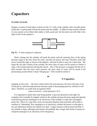
  • 1. Capacitors WATER ANALOG Imagine a system of water pipes as shown in Fig. 9.1, with a wide cylinder, and a movable piston inside that. A spring tends to keep the piston near the middle. A rubber O-ring around it (shown in cross section as two black dots) makes a fairly good seal, but the piston can still slide to the right or left if water pushes it. Fig. 9.1 A water analog of a capacitor. Water coming into the cylinder will push the piston until the restoring force of the spring becomes equal to the force from the water, and then all motion will stop. Therefore water that moves toward the right, as shown in the diagram, will only be able to move for a short time. The larger the size (the volume) of the cylinder, the more mass of water will be stored in it before it stops, with constant pressure driving the system. Also, if the pressure is changed, but the size is held constant, then the more water pressure, the more mass of water will be stored in the piston/spring system before it stops "charging up." (This would be similar to 89 9. Capacitors pumping air into a tire — the more volume and/or the more pressure, the more total mass of air will be put in, until the inside pressure becomes equal to the pumping pressure, and then it will stop.) Therefore, we could write an equation where (mass moved in) = (size) (pressure) (9.1) It is important to realize that water being pushed in just one direction (to the right, for example) will eventually be stopped, whenever the cylinder pressure becomes equal and opposite to the driving pressure (analogous to dc electricity). If the cylinder is small, this will happen pretty fast. However, water that is only moving short distances back and forth will be able to continue its "alternating" flow (analogous to ac electricity), whether the piston is in the pipe or not, provided those motions are indeed very short. Longer motions could go back and forth, if the cylinder is larger, although each motion will probably take a longer time before it reaches its end point (analogous to ac electricity of low frequency).
  • 2. These relationships are all close analogs to the behavior of electricity going into a capacitor, where mass of water is like coulombs of electric charge, size of the cylinder is like "capacitance," and pressure is like voltage. A bigger capacitor will allow longer-time back and forth alternations of electricity.* WHAT A CAPACITOR IS A capacitor (called a "condenser" in older literature) consists of metal plates, sep-arated by a thin layer of insulation, which could be vacuum or air, but usually is plastic or ceramic. When attached to a battery, electrons will flow onto one metal plate, and they are pulled off the other one, leaving positive charges there. COMMENT As the reader possibly knows, "electricity" in metal wires is entirely the flow of electrons, but protons or nuclei do not move very far through metal. However, it is convenient for us to imagine that either electrons are going in one direction or positive charges of some mysterious kind are going in the opposite direction, although not both at the same time in the same place (that would double the current). This is what the early scientific researchers believed, before electrons were discovered, and it is still a useful idea, even though only the first half of it is true. Sometimes the mathematical relationships in electronics, left over from the old days, are still written in terms of positive charges moving. This is especially found in older books about battery science, electroplating, and electric motors. * A small capacitor allows a small ac current. Thus the human body conduction on page 6. 9. Capacitors When the charge accumulates on the metal plates of a capacitor (see top of Fig. 9.2), a voltage appears, and this is equal to the total charge divided by the distance between the plates, as previously described in the dimensions at the bottom of page 15. If there is just vacuum between the plates, this situation is shown at the top of the figure. The meter is a high quality multimeter, which can measure the capacitance directly. (The meters used in this course do not, unless the instructor is able to obtain a special one for demonstrations.) It determines the + + ––
  • 3. Fig. 9.2 Capacitors, with vacuum or ceramic between the plates. amount of charge that flows into the capacitor when a certain voltage is applied from within the meter. When the voltage on the capacitor builds up to be equal to the driving voltage coming from the meter, the charging process stops. (Another useful analogy is to consider the capacitor to be like a very small storage battery, which will stop charging when its voltage becomes equal to the source voltage.) An important observation is that more charge can be put on the capacitor, at a given voltage, if the metal plates are closer together, as at the lower left side of Fig. 9.2. The reason for this (which quite surprisingly is not usually taught in physics or electronics courses) is that repulsion of the accumulated charges is what eventually stops further charges from coming onto the plates, but the electric field (page 15) from the positive plate neutralizes some of the field on the negative plate, and vice versa. This allows more charge to come in, before the flow finally stops. The closer the plates are together, the more neutralization occurs, and the more additional charge can come in. 9. Capacitors Capacitance, C, is the amount of charge, Q, per voltage, V, as in the following equation . Q (in coulombs) C(in farads) = ———————— (9.2) V (in volts) Therefore, by rearranging the terms, Q = CV, similar to eqn. 9.1 on page 90. Another useful relationship, somewhat difficult to find in most physics or electronics books, is (8.85 x 10⁻¹⁴ ) (k') (Area) C(in farads) = —————————— (9.3) (Thickness of insulator). The area and thickness are in cm2 and cm. The reader should note, from the 10-14 factor, that approximately one square centimeter of plate size (if the insulator thickness is also a centimeter) gives only a tiny fraction of a "farad" capacitance. Another way of saying this is that it would take about 1013 square centimeters of plate size to give a whole farad. Therefore, it can be seen that a farad is a huge quantity of capacitance. Most practical-sized capacitors have values that are only in the range of microfarads, usually
  • 4. referred to as "mfd." Sometimes the values are in picofarads ("pf," pronounced "puff," and equivalent to 10-12 farad). It would be useful if the k' factor could somehow be made to be a large number, to make up for the very small 10-14 . That k' factor is called the "relative dielectric constant," and it is dimensionless. If the insulator (which is referred to as the "dielectric" in physics) is a vacuum, then k' = 1. Common solid insulating materials like plastic or mica have k' values ranging from about 2 to 10. Therefore, putting them in between the plates instead of a vacuum raises the capacitance. This is shown at the lower right of Fig. 9.2, where the rectangle of solid dielectric allows more charge to accumulate on the plates, just like putting the plates closer together would have done. It should be noted that k' is the capacitance with a certain dielectric, divided by the capacitance with only a vacuum between the plates, and that is the reason for the word "relative." 9. Capacitors How does the dielectric material raise the capacitance? (Various other math is usually given in textbooks and courses, but again, the reasons "why" are usually not explained.) All solid materials consist of positively charged atomic nuclei, with electrons going around them in orbits. In the strong electric field caused by the charged metal plates, the electrons of the dielectric tend to "polarize," which means that they are attracted somewhat toward the positively charged plate (toward the top, in the lower-right diagram of Fig. 9.2). The more they can move, the more they polarize, and the higher their k' value is. In some materials they are more free than in others, although they all stop after going a few Angstroms of distance, because they are insulators. (If the charges continued to move, then these materials would be conductors, not insulators.) When the electrons can spend more time than usual up near the positive plate, their positively-charged nuclei (shown at the bottom of the rectangle in the figure) are exposed more to the negatively charged bottom plate. These positive fields tend to neutralize the negative charges on that plate, thus making less repulsion of new electrons, which can then move in. The more charges moving in at a certain voltage, the more capacitance, according to equation 9.2. With some modern dielectrics such as barium titanate or lead magnesium niobate ceramics,* the dielectric constant raises the capacitance 1,000 or even 20,000 times greater than with vacuum. Why not just make the spacing extremely small? Because the electricity can jump spontaneously across very small gaps, making sparks. Thin materials such as mica that can be put in between the plates and prevent sparks are said to have high "dielectric strength," which is not the same as having a high dielectric constant. Instead, it means that a very high voltage can be put across the insulator without causing "dielectric breakdown," in which a spark would "punch through" the material. The goal of modern capacitor design is to make the insulator be as thin as possible with a high dielectric strength, and also to have as high a dielectric constant as possible. A great deal of progress has been made in this technology during the last few years. (For examples, see pages 266 and 267.) Some capacitors are made by separating two very long strips of aluminum foil by a very thin sheet of plastic insulator. This sandwich is then rolled up into a convenient cylindrical shape, having a fairly large area (see eqn. 9.3) and a fairly small thickness.
  • 5. It should be intuitive that having a large area is equivalent to having many smaller-area capacitors hooked up in parallel, and this is quite true. A practical —————————— * Ceramics are made by sintering. More description is in the Glossary, page 274. 9. Capacitors way to have many in parallel is to use the multilayer configuration of Fig. 9.3. The black lines are metal layers, and insulating layers (not indicated specifically in the diagram) lie between them. The more insulator layers (four in this diagram), the more capacitance. Up to 100 layers are used in modern devices, also combined with ceramic dielectrics having high k' values. Fig. 9.3 A multilayer device, where the capacitance is multiplied by four. Just like pumping up a tire with compressed air, a capacitor will charge at the fastest "rate" in the beginning, as shown at the left side of Fig. 9.4. The rate is the slope of the curve at any given time point, and it is proportional to the current. As the capacitor voltage gets closer to the source voltage, of course the difference gets vanishingly small, and it is that voltage difference that drives the current. Therefore the current versus time curve (not shown) would look like the "discharging" curve at the right — high in the beginning and low later on. Theoretically, the end point would never quite be reached, but actually the current soon gets down into the random "noise" level, where it can no longer be measured and is effectively zero. The mathematical description is an "exponential" equation, similar to compound interest financial equations, or radioactive decay equations. These equations would probably not be useful to readers of this book, so they are only described briefly in the footnote.* (The Greek letter is explained on the next page.) CHARGING DISCHARGING V V ~ 2/3 Vmax ~ 1/3 V t max
  • 6. t Tau Tau Fig. 9.4 The voltage across a capacitor, versus time. * When charging, V = Vmax (1 – e – t/τ ). When discharging, V = Vmax (e – t/τ ). I = V / R. 9. Capacitors During discharging at the right side of the figure, the time it would take to get to zero voltage would be difficult to determine. Therefore, a more convenient discharging time is defined as the time it takes for the voltage to get to about 1/3 of the original maximum value. The ~ ("tilde") symbol means "approximately," and the exact fraction is 1/2.718, where the 2.718 is e, the base of the natural logarithm. This calculates to be about 37%, which is very roughly 1/3. This standard discharge time is usually called the time constant, and its symbol is the Greek letter τ ("tau"). During charging, the time to the full Vmax is theoretically infinite, as mention ed on the previous page. However, the more convenient charging time is the time it takes to get up to (1 – 0.37)Vmax , or about 63% of Vmax , and we can call that ~2/3 of the Vmax . Again, this is called the time constant, τ. A useful relationship is that the time constant is given by τ = RC (9.4) where R is whatever resistance is slowing down the charging or discharging, and τ is in seconds. In Fig. 9.5, it looks like that R is about 2,500 ohms, both for charging and for discharging. If the capacitance happens to be 1,000 mfd, that is the same as 0.001 farad. Then the time constant, τ, for either charging or discharging is (2,500)(0.001) = 2.5 seconds. EXPERIMENTS Voltage Versus Time The circuit of Fig. 9.5 should be constructed, where the "SPDT" switch is just a
  • 7. 9 Volts 9. Capacitors clip lead, with only one end attached to the 5K pot, and other end not being clipped onto anything. That loose end will later be touched to the battery's + terminal, and then later still, to the – terminal or any wire attached to it, which will make it equivalent to a single pole, double throw ("SPDT") switch. The term "double throw" means two possible positions, up and down as shown here. If it was a DPDT type (double pole, double throw), then there would be two switches hooked together mechanically, so two movable parts would simultaneously make contact with two upper terminals, or else with two lower terminals. Thus there would be 6 terminals altogether. At any rate, we will use no real switch at all, just a loose clip lead. Note the symbol for a capacitor, with a curved bottom line. Older literature used two straight lines, such as the one shown in the lower left of Fig. 9.2. However, that is the same as the symbol used by electricians to mean the contacts of a relay or switch, as will be discussed later in Chapter 12. To prevent misunderstandings, electronics engineers have changed their capacitor symbol to the one with a curved bottom. We will use a "polarized electrolytic" type with a capacitance of 0.001 farad, which is unusually large. The white arrow on the case points to the negative terminal, and the capacitor might be damaged if that wire is made positive for a long time. (The insulator inside is a very thin layer of aluminum oxide on a rolled up strip of aluminum foil. This oxide is generated electrolytically, and reversing the voltage could remove it.) Note also that if "leads" (wires coming out of a device such as a capacitor) have to be bent, they should come out straight for a short distance and then only be bent at a place several millimeters away from the device itself. On the other hand, if they are bent right at the edge of the device, then the insulation around the device is likely to become damaged. Adjusting the 5K pot (used here as a rheostat) to its highest resistance, and setting the multimeter on the 15 volts dc range, touch (or actually clip) the loose clip lead to the battery. The voltmeter will take a few seconds to reach the final 9 volt reading, following a curve like Fig. 9.4. Then touch the previously loose clip to a negative wire, and observe the discharge behavior. Turn the pot to a lower resistance setting, but not all the way to zero. Go through the same
  • 8. procedure and observe the faster time constant. The reasons for not using the minimum resistance setting are that (1) too much current would flow, possibly damaging the capacitor, and (2) all that current would go through a tiny area of resistor material inside the pot, overheating and probably destroying it. If the circuit was using that device as a true potentiometer, then during charging, the pot should not be set at the maximum voltage, because too much current would pass through a small area. 9. Capacitors Voltage Versus Current Set up the circuit of Fig. 9.6, which is the same as the one on page 83, except that the capacitor has been substituted instead of the light bulb. The arrow on the outside of the capacitor should point to the ground, since that is negative. The scope settings can be the same as on page 84, but the sensitivities can be changed somewhat if desired, because the voltages and currents do not have to be so high this time. If the battery polarity is reversed (and the NORM / INV button is pressed), then the capacitor leads can also be reversed, although using it the wrong way for a short time will not really hurt it. A curve similar to the one for the light bulb is observed, except that when the pot is turned down again, a reverse current flows, while the capacitor ("cap") is discharging, and this did not happen with the bulb. At any rate, the current changes (either increasing or decreasing) first, while the cap is charging or discharging, and then the voltage changes a short time later. Going up and down quickly with the pot makes a complete oval pattern on the scope screen. SAFETY NOTE: Whenever anything is plugged into the 120 V ac wall socket, as it will be in the next experiment, it would be best to have it go through a ground fault interrupter. Even the small 12 V transformer could possibly have an internal short circuit from a primary wire to the
  • 9. metal case, or to one of the 9. Capacitors secondary wires. Although that seems unlikely, if thousands of people read this book and do the experiments, it could happen to one person. If a GFI is not available, then the instructor might use a neon tester, having one hand on one wire and touching the other wire (page 5) to each 12 V transformer's metal case and secondary wire in the class, while the power cords are plugged in. In addition, and more important, students should observe the one-hand rule (page 4) when using 120 volts. In this experiment, plug in the transformer and use its 12 V secondary instead of the battery. With the X versus Y type of scope display, a continuous oval pattern is observed, which is called a "Lissajous figure," named after an early scientist. The vertical VOLTS/DIV knobs, and also their smaller VARIABLE knobs, can be adjusted to other settings such as >5V / div for X and <20 mV / div for Y, in order to make the scope pattern become nearly a perfect circle. Switching the MODE from CH2 to DUAL and TIME/DIV from X-Y to 20 ms will provide a two-wave display, much like the right-hand side of Fig. 9.7. (Unplug the BNCs before the transformer, to avoid an inductive kick.) Phase (No experiments, except for the optional one on page 100) Why does the voltage build up later than the current? The answer is possibly known to the reader, but a lot of thought should be devoted to this point, since it is useful in many areas of electronics. At the left of Fig. 9.7 is a pendulum, in PENDULUM CAPACITOR Fig. 9.7 "Out of phase" situations in a pendulum and a capacitor. 9. Capacitors which the velocity is out of phase with (does not reach its maximum at the same time as) the force that causes it. At first sight, one might expect that, at the very instant when the downward
  • 10. force is greatest (at the position farthest to the right), the velocity should be greatest, and when the gravitational force is zero, then the velocity should also be zero. However, that is not the case, as indicated at the left-hand part of the figure. The reason why force and velocity are "out of phase" is that one of them (velocity) is cumulative and must build up, increment by increment, in order to reach its maximum value. The other one (force) is applied by gravity instantaneously. (Note that it is dependent on the "resolution of forces," where the strength of the pendulum shaft prevents any gravitational driving force at the very bottom of the swing). This is an easily understood analog of things that happen in electronics, where one thing (not necessarily a "driving force") is instantaneous, and another is cumulative, so their maxima occur at different times. The times are referred to as the "phases," and they are compared to the time it takes to complete one whole cycle. In 60 Hz (60 cycles per second) ac electricity, one whole cycle takes 1/60 of a second, but another way of looking at it is to consider a cycle as if it was something rotating, going 360 degrees from start to finish. (Actually, the electric generator that makes the ac is really rotating.) In a capacitor, since the voltage is cumulative, it is delayed, and the amount of delay is referred to in terms of degrees instead of by fractions of a second. In this case, the delay (called "lag" in electronics) is 90 degrees. Therefore we can say "the voltage and current are 90° out of phase, and the voltage is lagging." Another way to say the same thing is "the current leads the voltage by 90°." These relationships are quite important in motors, oscillators, etc. OPTIONAL Reactance Since low frequency ac has difficulty going through a capacitor, there must be something similar to resistance, which the capacitor presents to the electricity. This "something" is called reactance. It does decrease the current flow, but it does other things also, and it can be considered to be a sort of overall effectiveness of the capacitor. The "capacitive reactance" (to distinguish it from "inductive reactance," which we will see later) is Xc in equation 9.5. 1 Xc = ————— (9.5) 2 π f C Pi is the usual 3.14, f is the frequency in Hz, and C is the capacitance in farads. 100 9. Capacitors If an ordinary resistor is put in series with a capacitor, the situation might be as shown in Fig. 9.8. Actually, there will always be some resistance (unless superconductors are used!), including the small but often important resistance of the capacitor plates themselves, and various solder joints and contacts. An optional experiment that the reader might try is to put a 100 ohm resistor in series with the 1,000 mfd capacitor and then do the experiment of Fig. 9.6 over again (but with 150 Ω replacing the 100 Ω shown in the figure). The circular Lissajous figure without the resistor becomes an oval, if 100 Ω is in series. When this resistance is not external but instead is inside the capacitor (in the plates, etc.), it can be important in some applications. Even though it
  • 11. might be a "distributed resistance" all throughout the device, one can imagine it to be a single external resistor as in Fig. 9.8. In that case it is called "equivalent series resistance," or ESR. It is part of the specification of high quality devices. The value of the ESR can be calculated from the width of the Lissajous figure (page 98), if precisely calibrated equipment is used. ("Distributed capacitance" can also exist, when two insulated wires are close together, which is often important at high frequencies.) Another possible case would be resistance that might be in parallel, as shown by the dashed lines in the diagram. It is not practical to measure this with the inexpensive equipment being used in this laboratory course (although the reader is encouraged to try it as an optional exercise), because the 1,000 mfd capacitor offers such a low resistance to 60 Hz ac that only a negligible effect can be seen on the scope when a 100 ohm resistor is put in parallel. (According to eqn. 9.5, this capacitor should have an effect similar to that of a 0.38 ohm resistor.) 9. Capacitors 101 With a series resistance, the total resistance to ac will be more than that of either device alone, and the effective value of this total is called impedance, which is Z, as follows: (9.6) (A rule similar to Ohm's law still applies, so the current still is given by V / Z.) It is convenient in electronics to use a type of vector for this relationship, called a "phasor," as in Fig. 9.8. Note that the Z vector, the long-dash line, is the hypotenuse of the triangle made by the R and Xc vectors (solid lines).
  • 12. X = Reactance Z = Impedance Delta Phase R = Resistance Fig. 9.9 "Phasors," which will be used in Chapter 16 (page 179). The angle between Z and R is called the "phase angle," symbolized by the Greek letter φ ("phi"), and its value is 45° in Fig. 9.7, but it can be adjusted by changing R. For a pure capacitance having zero series resistance, the phase is 90°, but for a pure resistance it is zero. The other angle, 90° – φ , is called δ ("delta"). Note that the R / X is the tangent of delta, and in fact it is referred to quite often in discussions about capacitors. Synonyms used in specifications ("specs") include: R / X = "tanδ "= "loss" = "dissipation factor." Loss can be calculated from the width and length of the Lissajous figure. Dielectric heaters involve lossy capacitance (see also the middle of page 212). There is another term that is important in the sharpness of tuning (as with a radio receiver getting mostly just one station but very little of another station). This is the "quality factor," or Q, which is X / R or tan φ. Still another relationship that the reader might encounter, especially when dealing with electric heaters or motors is the "power factor," which is R / Z. The power obtainable from those devices can be severely limited if the current is too far out of phase with the voltage. There might not be sufficient voltage at the right time to drive high currents through a useful load. 102 9. Capacitors
  • 13. LOSSLESS CONTROL There are three ways to decrease the power going to an electric heater or other device, in order to control it. For a house that is directly heated by electric heating elements mounted in the walls, one way to control the temperature would be to put a giant rheostat in series with the heaters. It should be apparent to the reader that such a method would waste a lot of power, right inside the big rheostat, which is itself a heating element (it is "dissipative"). Another way to control the power is to simply turn it all the way on when heat is needed and completely off when not needed. This is the way that most home heating (and also air conditioning units) are controlled. However, the variable being controlled (temperature in this case) tends to "overshoot" the desired value. If the turn-on and turn-off operations could be done very often, there would be less overshoot, but the electromechanical parts of oil burners and air conditioners would wear out fast if this were done in home units. It should be noted that there is no resistive loss of power, and in fact this fast on-off operation is actually done in some kinds of strictly electronic power controllers. A third way is to put a big variable-capacitor in series with the heater, because capacitive ("reactive") limiting of ac has no loss, at least with nearly-perfect capacitors. This method of controlling ac is hardly ever used, because capacitors that are variable and are "nearly perfect" (practically no ESR) would be very expensive to manufacture. (A similar concept will be described at the end of the next chapter, where a different kind of reactance is often used to control power.) A perfect capacitor does not have the loss expected with a resistor. Therefore, a pure reactance, X, is sometimes treated mathematically in terms of "imaginary" numbers involving the square root of minus one, but we will not use those here. EQUIPMENT NOTES Components For Radio Shack This Chapter Catalog Number Battery, nine volts 23-653 Clip leads, 14 inch, one set. 278-1156C Multimeter (or "multitester") 22-218 Capacitor, 1000 mfd 272-1019 or 272-1032 Potentiometer, 5K 271-1714 or 271- 1720 Resistor, 100 ohm, 10 or 1 watt 271-135 or 271-152 Resistor, 150 ohm (for optional exper., page 100) 271-306 or 271-308 Oscilloscope, Model OS-5020, made by LG Precision Co., Ltd., of Seoul, Korea