SlideShare a Scribd company logo
1 of 89
Download to read offline
Performance with a refined new design and functional beauty
(Note)
Mark indicating China
Compulsory Certification
approval.
(Note)
Mark indicating EC
Command compliance.
Products with CE Mark
can be used in Europe.
(Note)
Mark indicating TUV
Rheinland Group
certification.
(Note)
Mark indicating product
UL/CSA certification by
Underwriter’s Laboratory.
MAGNETIC MOTOR STARTERS
AND MAGNETIC CONTACTORS
seriesseries
Incorporation of CAN terminal for simple wiring
Unified design for N series
The design has been unified for the MS-N series.
The front face of the product is a bright white color, making the
inside of the panel brighter and providing a clean image.
Arc space reduced to approx. one-third!
By adopting the new extinguishing mechanism, the arc
space has been reduced to approx. 1/3 (Mitsubishi
comparison).
Compatible with International Standards
Most of Mitsubishi's standard products comply with International
Standards.
Applicable standards: JIS, JEM, IEC, EN, VDE, BS
Approved standards: UL, CSA, LR, BV, NK, KR, TÜV, GB
By adopting a CAN terminal, there is no need to remove the
screws, and losing of the terminal screw is prevented by the
integrated screw holder and terminal screw. The terminal screw
is set in a plastic screw holder. When each pole is moved and the
screw loosened, the screw is naturally set in the screw holder.
This is Mitsubishi's original CAN terminal. (Patented)
(S-N10CX~N35CX, SD-N11CX~N35CX, SR/SRD-N4CX)
Substantial safety and
functionality realized
with a full lineup
Simple inspections
The contactor can be inspected easily by removing the arc cover.
Built-in surge absorber
The model with built-in surge absorber for coils is obtainable as
an option.
Pull up the screw holder. Insert the closed eyelet connector,
and push up the screw holder.
Tighten the screw.
Stronger barrier strength is improved with the thermoplastic mold.
Improved magnet
By using a spiral kick-out spring, the dynamic balance of the
moving parts is improved, bouncing is reduced, and the core life
is extended. Furthermore, the core movement is generally
stabilized. The efficient magnet has been achieved through
modern technology of the magnet section using a computer. The
contactor has a performance to withstand a voltage drop to 35%
with the closed contact.
Spiral kick-out
spring
Coil
Moving core
Stationary
core
Small-Sized Models
S-N10~N35
15mm 15mm 15mm 15mm 15mm
38.5mm
Indication of absorber Surge absorber
Simple installation and wiring
The MS-N series contactors, starters and relays can be installed on a
mounting rail (35mm width). The terminals of these coils are arranged
on the contactor with simple wiring. Furthermore, the distance between
the center of the rail and the coil terminals is unified at 38.5mm.
(S-N10 to N21, MSO-N10 to N21 and SR-N4)
CAN terminal realizes safety and speedy
The models with finger protection are safer and speedier even if
the lug of a closed type eyelet (ring) terminal plate is used.
(S-N10CX~N35CX, SD-N11CX~N35CX, SR/SRD-N4CX)
Medium-and Large-Sized Models:
S-N50~S-N800
DC Electromagnet with AC
Operation (Patented)
Even Greater Contact Reliability
MATCH WITH ELECTRONIC
CONTROL FOR FACTORY AUTOMATION
If the magnetic relay coil is opened and closed near an electronic
circuit, malfunctioning of the electronic circuit could be induced
by a surge voltage. The UN-SA type surge absorber suppresses
the surge voltage when this coil is opened and closed. In
addition to the general varistor
type and the CR type that lays
importance on suppressing the
induction voltage when starting,
the type with operating indicator
(varistor type), and the varistor
type with CR are available.
One-touch surge absorber
An easy-to-install terminal cover, which lays importance on
further safety and is compatible with finger protection, has been
prepared.
Finger Protection Compatible
A new extinguishing structure, which eliminates the blow off of
hot gas (arc) to the front (direction to door of control panel)
when the current is cutoff has been incorporated.
In addition to improved safety, the freedom of panel design has
been increased allowing space to be saved.
The arc blowoff direction has been changed to
further improve safety and space conservation
This is an auxiliary contact unit with low level contact, capable of
opening and closing the low voltage and minute current of the
electronic control circuit. It can be installed with one touch onto
the magnetic contactor or magnetic relay that opens and closes
the power of the motor, etc. The junction relay for opening and
closing the low voltage and minute current is not needed, so
this unit is suitable for opening and closing electronic input
circuits in programmable logic controllers, etc. A compact
microswitch is used for the low level contact, so the unit will not
malfunction due to fields and
surge voltages from the main
circuit current and coil of the
magnetic contactor.
A 1NO+1NC low level contacts
and 1NO+1NC standard contacts
are built-in, so the opening and
closing of 200VAC and 24VDC
can be handled with one unit.
Auxiliary contact unit with low level contact
S2 types of inputs
The long life no-contact output type (UN-SY21, SY31) and
contact output type (UN-SY22, SY32) are available.
SOne touch installation
The UN-SY21, SY22, SY31 and SY32 types can be mounted with
one touch onto the coil terminal. Post-installation work is easy.
SSingle standalone unit
A single unit installation type
(UN-SY11, SY12) is available for
the S-KR11 and S-N80 to N400
magnetic contactor.
Interface unit
Coil power consumption is greatly low so MS-N Series
contactors can be controlled by almost any type of relay, even
small output relays of programmable controllers.
Lower Power Consumption
When switching a coil, the energy will be desipated within internal
circuit of electromagnet
Contact reliability has been greatly improved by the bifurcated
auxiliary moving contact
Less Noise nor Surge from Coil
The voltage rating ranges is widened and the coil type are
reduced to one-third.
Contactor Coils Have Ultra-Wide Range of Ratings
DC excitation does not cause humming so operation is quiet.
Internal circuit of the electromagnet
Humming Completely Eliminated
S-N
5
10
10
10
10
Frame
N50/N65
N80/N95
N125~N220
N300/N400
N600/N800
S-K
10
10
30
50
10
Arc space(mm)
Direct installation is possible on the following units:
S-N series (Magnetic contactor) 65A frame or less
SR-N series (Magnetic relay) 4-pole, 5-pole and 8-poles types
C
Coil
R
Contact
spring
Bifurcated moving
contact
Bifurcated
moving
contact
Stationary
contact
Arc space
TYPE REFERENCE LIST ........................................................................................................................................ 1
1. GENERAL PURPOSE CONTACTORS & STARTERS ........................................ Series MS-N
1.1 Conformity to International Standards ....................................................................................................... 2
1.1.1 List of Marked Type ............................................................................................................................. 3
1.1.2 TÜV Certified Type ................................................................................................................................... 3
1.1.3 UL Approval for U.S.A. and Canada ......................................................................................................... 5
1.1.4 CCC Certified Products ............................................................................................................................ 7
1.1.5 Approved Marine Standards ................................................................................................................... 11
1.2 Selection Guide ........................................................................................................................................... 12
1.3 The Overview (Type designation breakdown).......................................................................................... 14
1.3.1 Non-Reversing Types ............................................................................................................................. 14
1.3.2 Reversing Type....................................................................................................................................... 15
1.4 Technical Data of Series S-N Contactors ................................................................................................. 16
1.4.1 Ratings and Characteristics .................................................................................................................... 16
1.4.2 Performance of Series S-N Contactors .................................................................................................. 18
1.4.3 Mounting Attitude of Starters and Contactors ......................................................................................... 18
1.5 When Ordering ............................................................................................................................................ 19
1.6 Selection Table of Contactors ................................................................................................................... 20
1.6.1 Non-Reversing Contactors ............................................. Type S-N , SD-N ......................................... 20
1.6.2 Reversing Contactors ..................................................... Type S-2xN , SD-2xNN .............................. 21
1.6.3 Non-Reversing Mechanically Latched Contactors .......... Type SL-N , SLD-NN .................................. 22
1.6.4 Reversing Mechanically Latched Contactors.................. Type SL-2xN , SLD-2xN , SLxS-NN ............. 23
1.7 Selection Table of Direct-On-Line Motor Starters.................................................................................... 24
1.7.1 Non-Reversing Motor Starters without Enclosure(IP 00) Type MSO-N ................................................. 24
1.7.2 Reversing Motor Starters without Enclosure(IP 00)........ Type MSO-2xN ............................................. 25
1.7.3 Enclosed Non-Reversing Motor Starters(IP 20) ............. Type MS-N .................................................... 26
1.7.4 Enclosed Non-Reversing Motor Starters with Pushbutton Switch(IP 20) ............. Type MS-N PM ................. 27
1.8 Optional Parts and Accessories for Contactors ...................................................................................... 28
1.8.1 Replacement Coils.................................................................................................................................. 28
1.8.2 Replacement Contact Kits ...................................................................................................................... 28
1.8.3 Auxiliary Contact Blocks ......................................................................................................................... 29
1.8.4 Mechanical Interlocks ............................................................................................................................. 29
1.8.5 Connecting Bar Kits ................................................................................................................................ 29
1.8.6 Surge Absorbers ..................................................................................................................................... 30
1.8.7 Terminal Covers ..................................................................................................................................... 30
1.8.8 Pneumatic Time Delay Modules ............................................................................................................. 30
1.8.9 DC Interface Modules ............................................................................................................................. 30
1.9 Connections and Contact Arrangement ................................................................................................... 31
1.9.1 S, SD-N...................................................................................................................................................31
1.9.2 S, SD-2xN ............................................................................................................................................... 32
1.9.3 SL, SLD-(2x)N ........................................................................................................................................ 33
1.9.4 MSO-(2x)N.............................................................................................................................................. 34
1.9.5 MS-N....................................................................................................................................................... 35
1.9.6 MS-N PM .............................................................................................................................................. 35
1.10 Outline Dimensions .................................................................................................................................. 36
1.10.1 Outline Dimensions of Non-Reversing Contactors ............................................................................... 36
1.10.2 Outline Dimensions of Reversing Contactors ....................................................................................... 37
1.10.3 Outline Dimensions of Open Type Starters .......................................................................................... 38
1.10.4 Outline Dimensions of Enclosed Motor Starters ................................................................................... 39
CONTENTS
2. MOTOR PROTECTION RELAYS
2.1 Thermal Overload Relays ............................................................................. Series TH-N ........................ 40
2.1.1 Selection Guide of Thermal Overload Relays......................................................................................... 41
2.1.2 Selection Guide of the Current Transformers for TH-N600KP ............................................................... 42
2.1.3 Technical Data ........................................................................................................................................ 42
2.1.4 Selection Guide of Quick Trip Thermal Overload Relay ......................................................................... 42
2.1.5 Operating Characteristics of Thermal Overload Relays ......................................................................... 43
(Connecting wire size : Refer to “standard wire size” of Table 2.1.3)
2.1.6 Optional Parts and Accessories.............................................................................................................. 44
2.1.7 Outline Dimensions................................................................................................................................. 45
2.2 Electronic Motor Protection Relays ............................................................ Series ET-N ........................ 46
3. DEFINITE PURPOSE CONTACTORS & STARTERS
3.1 DC Contactors ............................................................................................... Series DU-K/A .................... 49
3.2 Medium Voltage Vacuum Contactors ......................................................... Series SH-V ........................ 52
3.3 Compact 3-Pole Contactors ......................................................................... Series S-N 8 .................... 55
3.4 NC Main Contact Contactors ....................................................................... Series B-N .......................... 56
3.5 Delay Open Type Magnetic Starters & Contactors .................................... Series S/MSO-N DL ........ 58
3.6 DC Interface Contactors ............................................................................... Series SD-Q ....................... 60
3.7 DC Interface Modules ................................................................................... Series UN-SY ..................... 63
4. RELAYS
4.1 Contactor Relays .......................................................................................... Series SR-N ........................ 65
4.1.1 Specifications.......................................................................................................................................... 66
4.1.2 Auxiliary Contact Blocks ......................................................................................................................... 67
4.1.3 Contact Arrangements of Contactor Relay ............................................................................................. 68
4.1.4 Spare Coils & Accessories ..................................................................................................................... 68
4.1.5 Outline Dimensions................................................................................................................................. 68
4.2 Voltage Detection Relays ............................................................................. Series SRE ......................... 69
4.3 Re-Starting Relays ........................................................................................ Series UA-DL ..................... 71
4.4 Solid State Time Delay Relays ..................................................................... Series SRS-H ..................... 73
4.5 Pneumatic Time Delay Relays ..................................................................... Series SRT-N ..................... 74
5. STAR-DELTA STARTERS ................................................................................... Series EYD-N
5.1 Selection Table............................................................................................................................................ 76
5.2 Specifications.............................................................................................................................................. 77
5.3 Outline Dimensions .................................................................................................................................... 78
5.3.1 Open Type (EYDO-N)............................................................................................................................. 78
5.3.2 Enclosed Type (EYD-N) ......................................................................................................................... 78
6. SOLID STATE CONTACTORS ............................................................................ Series US-N/K, H
6.1 Features ....................................................................................................................................................... 79
6.2 Product Scope............................................................................................................................................. 80
1
TYPE REFERENCE LIST
DescriptionType
NC main contact contactors ............................................................................................56
DC contactors..................................................................................................................49
Electronic motor protection relays ...................................................................................46
Star-delta starters ............................................................................................................76
General purpose enclosed type motor starters ...............................................................26
Enclosed non-reversing motor starters with pushbutton switch ......................................27
General purpose open type motor starters......................................................................14,24,38
Delay open type magnetic contactors .............................................................................58
General purpose open and reversing type motor starters ...............................................15,25,38
Plug-in sockets for,UA-DL2 .............................................................................................72
Compact 3-pole contactors .............................................................................................55
General purpose contactors ............................................................................................2~
DC interface contactors ...................................................................................................60
Delay open type magnetic contactors .............................................................................58
General purpose reversing contactors ............................................................................32
Medium voltage vacuum contactors ................................................................................52
Medium voltage reversing vacuum contactors ................................................................52
Mechanically latched contactors .....................................................................................22
Mechanically latched reversing contactors......................................................................23
Mechanically latched and normal reversing contactors...................................................23
Contactor relays ..............................................................................................................65
Voltage detection relays ..................................................................................................69
Solid state time delay relays............................................................................................73
Pneumatic time delay relays ...........................................................................................74
Thermal overload relays ..................................................................................................40
Saturable reactors for TH-N ............................................................................................44
Auxiliary contact blocks for SH-V ....................................................................................54
Re-starting relay ..............................................................................................................71
Surge absorbers for SH-V ...............................................................................................53
Auxiliary contact blocks ...................................................................................................29,50,67
Mechanical interlocks for S-N..........................................................................................29
Reset release for TH-N ...................................................................................................44
Surge absorbers for S-N and SR-N4...............................................................................30
DC interface modules for S-N .........................................................................................30,63
Trip indicator for TH-N .....................................................................................................44
Pneumatic time delay modules .......................................................................................30,78
Solid State Contactors.....................................................................................................79
Ref.Page
B(D)-N
DU(D)-
ET-N
EYD(O)-N
MS-N
MS-N PM
MSO(D)-N
MSO-N DL
MSO(D)-2XN
PF-
S-N 8
S(D)-N
SD-Q
S-N DL
S(D)-2XN
SH(L)(D)-V
SH(L)(D)-2XV
SL(D)-N
SL(D)-2XN
SLXS-N
SR(D)-N
SRE-
SRS-H
SRT(D)-N
TH-N
THR-
UA-AXVV
UA-DL2
UA-SU
UN-AX
UN-ML
UN-RR
UN-SA
UN-SY
UN-TL
UN-TR
US-N /K
US-H
2
1. GENERAL PURPOSE CONTACTORS & STARTERS
1.1 Conformity to International Standards
Series MS-N
Mitsubishi magnetic motor starters and contactors are designed to conform to the
relevant IEC recommendations and to the standards of as many countries as
possible. Specifically, they conform to the following:
VDE0660
NEMA-ICS
IEC60947-4-1
EN60947-4-1
International
Europe
Germany
U.S.A
Table 1.1
DC
Operated
Contactor
Overload
Relay
AC
Operated
Contactor
Type
(✽2)
Canada
U.K. France Korea Japan
Lloyd’s
Register of
Shipping
Korean
Register of
Shipping
Bureau
Veritas
Nippon
Kaiji
Kyokai
AC
Operated
Contactor
Relay
DC
Operated
Contactor
Relay
Auxiliary
Contact
Block
U.S.ACanadaU.S.A
Listing Recognition
Europe North America / UL
TÜVCE Mark
᭺
— — — — —
●
(✽2)
᭺
(✽2)
●
(✽2)
᭺ — ᭺ ——
᭺ ᭺
᭺ ᭺
᭺ ᭺
✩
— —
᭺ ᭺
᭺ ᭺
᭺ ᭺
᭺ ᭺
— —
— —
— —
—
— —
—
᭺
—
—
᭺
Marine
( Mark)
( Mark)
( Mark)
( Mark)
( Mark)
( Mark)
—
᭺
(✽2)
✩
( Mark)
( Mark)
( Mark)
(✽2)
Model Name
SR-N4(CX)
SRD-N4(CX)
UN-AX2(CX)
UN-AX4(CX)
UN-AX11(CX)
UN-AX80
UN-AX150
S-N10(CX)
S-N11(CX)/N12(CX)
S-N18(CX)
S-N20(CX)/N21(CX)
S-N25(CX)
S-N35(CX)
S-N28(CX)
S-N38(CX)
S-N48(CX)
S-N50
S-N65
S-N80
S-N95
S-N125
S-N150
S-N180
S-N220
S-N300
S-N400
S-N600
S-N800
TH-N12(CX)KP
TH-N18(CX)KP
TH-N20(TA)(CX)KP
TH-N60(TA)KP
TH-N120(TA)KP
TH-N220RHKP/HZKP
TH-N400RHKP/HZKP
SD-N11(CX)/N12(CX)
SD-N21(CX)
SD-N35(CX)
SD-N50
SD-N65
SD-N80
SD-N95
SD-N125
SD-N150
SD-N220
SD-N300
SD-N400
SD-N600
SD-N800
China
CCC
certification
—
Notes:1. : CE Mark (Manufacturer’s Declaration) == Standard model applicable, marking on the product.
UL, TÜV, CCC == Standard model applicable, marking on the product.
NK == Standard model applicable, Certificate No. on the product.
● : Standard model applicable, no marking on the product. If marking required, order model name followed by suffix “DZ”.
᭺ : Standard model applicable, no marking on the product.
✩ : Special model applicable, marking on the product. Order model name followed by suffix “UL”.
★ : China export applicable, no marking on the product. Ensure to add “CN” after the model name when placing an order.
— : Not applicable to the Standard or not approved.
2. Finger protection type is certified according to DIN VDE 0106 part 100. For finger protection type, order model name followed by suffix “CX”.
3. For each certificate conditions, see next three pages.
★
★
★
3
Notes:1. Listed types are representatives and containes standard models.
2. Applicable product standards
Contactors : EN60947-1, EN60947-4-1, EN60947-5-1
Thermal overload relays : EN60947-1, EN60947-4-1, EN60947-5-1
Aux. contact blocks : EN60947-1, EN60947-5-1
Mechanical interlocks : EN60947-1, EN60947-4-1, EN60947-5-1
3. For mechanical interlocks, no marking on the product. Mechanical interlocks are applicable when used in reversing contactors.
4. Necessary to connect a varistor etc., in order to provide compliance for CE marking for the US-N5/N8SS(TE)and US-N(H) 70/N(H)
80NS(TE) type.
1.1.1 List of Marked Type
Standard Contactors
Non-reversing
A.C. operated
D.C. operated
A.C. operated
D.C. operated
Additional Auxiliary Contact Blocks
Standard Contactors
Reversing
Mechanical Interlocks3
S-N10, S-N11, S-N12, S-N18, S-N20, S-N21, S-N25, S-N28, S-N35, S-N38, S-N48, S-N50, S-N65, S-N80,
S-N95, S-N125, S-N150, S-N180, S-N220, S-N300, S-N400, S-N600, S-N800
SD-N11, SD-N12, SD-N21, SD-N35, SD-N50, SD-N65, SD-N80, SD-N95, SD-N125, SD-N150, SD-N220,
SD-N300, SD-N400, SD-N600, SD-N800
S-2XN10, S-2XN11, S-2XN20, S-2XN21, S-2XN25, S-2XN35, S-2XN50, S-2XN65, S-2XN80, S-2XN95,
S-2XN125, S-2XN150, S-2XN180, S-2XN220, S-2XN300, S-2XN400, S-2XN600, S-2XN800
SD-2XN11, SD-2XN21, SD-2XN35, SD-2XN50, SD-2XN65, SD-2XN80, SD-2XN95, SD-2XN125, SD-2XN150,
SD-2XN220, SD-2XN300, SD-2XN400, SD-2XN600, SD-2XN800
UN-AX2, UN-AX4, UN-AX11, UN-AX80, UN-AX150, UQ-AX2(KR)
UN-ML11, UN-ML21, UN-ML80, UN-ML150, UN-ML220
Thermal Overload Relays TH-N12KP, TH-N18KP, TH-N20KP, TH-N20TAKP, TH-N60KP, TH-N60TAKP, TH-N120KP, TH-N120TAKP,
TH-N220RHKP, TH-N220HZKP, TH-N400RHKP, TH-N400HZKP, TH-N600KP
Contactor Relays A.C. operated
D.C. operated
D.C. Interface Contactors Non-reversing
Reversing
SR-N4
SRD-N4
SD-Q11, SD-Q12, SD-Q19
SD-QR11, SD-QR12, SD-QR19
Table 1.1.1
Solid state Contactors (for motor/heater load)
Solid state Contactors (for heater load)
US-N5SS(TE), US-N8SS(TE), US-N20(TE), US-N30(TE), US-N40(TE), US-N50(TE), US-N70NS(TE), US-N80NS(TE),
US-NH70NS(TE), US-NH80NS(TE), US-N20(TE)CX, US-N30(TE)CX, US-N40(TE)CX, US-N20(TE)RM
US-H20(DD), US-H30(DD), US-H40(DD), US-H50(DD), US-H20(DD)RM, US-H30(DD)RM
Notes:1. Standard models are applicable under following conditions.
Main circuits : AC-3 rated current at 440V AC max.
(Main contacts) and rated continuous current.
Auxiliary contacts : AC-15 rated current at 550V AC max.
and rated continuous current.
Operation coil : AC coil designation
N10~N12, N18~N48 and SR-N4 ; AC12V~AC440V
N20~N35 ; AC12V~AC380V
N50~N150 ; AC24V~AC500V
N180~N400 ; AC48V~AC500V
DC coil designation DC12V~DC220V
2. For contactors, standard models are with TÜV mark on the product.
For other products, standard models are with no TÜV mark on the product.
3. Finger protection type is certified according to DIN VDE 0106 part 100. For finger protection type, order model name followed by suffix “CX”.
4. Models with built-in surge absorber (model name followed by “SA”) are also certified.
5. Mirror contact function compliance certification has been obtained from TÜV. This product is suitable for use in a machine tool's interlock circuit. The mirror
contact function refers to a function in which the auxiliary NC contact can withstand a 2500V impulse voltage without contacting even if the main contact melts.
1.1.2 TÜV Certified Type
■ Contactor Table 1.1.2 (1)
S-N10(CX)(SA)
S-N11(CX)(SA)
S-N12(CX)(SA)
S-N20(CX)(SA)
S-N21(CX)(SA)
S-N25(CX)(SA)
S-N35(CX)(SA)
S-N18(CX)(SA)
S-N28(CX)(SA)
S-N38(CX)(SA)
S-N48(CX)(SA)
S-N50/S-N65
S-N80/S-N95
S-N125
S-N150
S-N180/S-N220
S-N300/S-N400
SD-N11(CX)(SA)
SD-N12(CX)(SA)
SD-N21(CX)(SA)
SD-N35(CX)(SA)
SD-N50/SD-N65
SD-N80/SD-N95
SD-N125
SD-N150
SD-N220
SD-N300/SD-N400
Model Name Certificate No.
EN60947-4-1 R9551340
Applicable standard
Mirror contact5
Internal auxiliary NC contact
Auxiliary contact block
Auxiliary NC contact
EN60947-4-1
EN60947-4-1
EN60947-4-1
EN60947-4-1
EN60947-4-1
EN60947-4-1
EN60947-4-1
EN60947-4-1
EN60947-4-1
EN60947-4-1
EN60947-4-1
EN60947-4-1
EN60947-4-1
EN60947-4-1
EN60947-4-1
EN60947-4-1
EN60947-4-1
R9651190
R9651189
R9851170
R9851138
R9851169
R9851167
R9851164
R9851171
R9551336
R9651190
R9851170
R9851138
R9851169
R9851167
R9851164
R9851171
R9551340
᭺
—
᭺
᭺
᭺
᭺
᭺
᭺
—
—
᭺
(UN-AX2(CX), UN-AX4(CX))
᭺ (UN-AX2(CX), UN-AX4(CX))
—
᭺
(UN-AX150)
᭺
(UN-AX2(CX), UN-AX4(CX))
᭺
(UN-AX150)
EN60947-4-1 R9551336
Solid state Contactors : EN60947-4-2, EN60947-4-3
(for motor/heater load)
Solid state Contactors : EN60947-4-3
(for heater load)
4
Notes:1. Standard models are applicable under following conditions.
Main circuits : AC-3 rated current at 440V AC max.
(Main contacts) and rated continuous current.
Auxiliary contacts : AC-15 rated current at 550V AC max. (SD-Q(R)11~Q(R)19 : 440V AC max.)
and rated continuous current.
Operation coil : AC coil designation
SR-N4 ; AC12V~AC440V
DC coil designation DC12V~DC220V (SD-Q(R)11~Q(R)19 : DC12V~DC24V)
2. For contactors, standard models are with TÜV mark on the product.
For other products, standard models are with no TÜV mark on the product.
For contactor relays, order model name followed by suffix “DZ” if TÜV mark on the product is required.
3. Finger protection type is certified according to DIN VDE 0106 part 100. For finger protection type, order model name followed by
suffix “CX”.
4. Models with built-in surge absorber (model name followed by “SA”) are also certified.
5. Miller contact function compliance certification has been obtained from TÜV. This product is suitable for use in a machine tool's
interlock circuit. The miller contact function refers to a function in which the auxiliary NC contact can withstand a 2500V impulse
voltage without contacting even if the main contact melts.
6. If the SD-Q11 with 1NC is required, it must be so indicated when placing an order.
■ Thermal Overload Relay
TH-N12(CX)KP
TH-N18(CX)KP
TH-N20(TA)(CX)KP
TH-N60(TA)KP
TH-N120(TA)KP
TH-N220RHKP/HZKP
TH-N400RHKP/HZKP
Model Name Applicable standard Registration No.
EN60947-4-1
EN60947-4-1
EN60947-4-1
EN60947-4-1
EN60947-4-1
EN60947-4-1
EN60947-4-1
J9551338
J9551338
J9551341
J9851140
J9851168
J9851166
J9851172
Table 1.1.2 (3)■ DC Interface Contactor
SD-Q11
SD-Q12
SD-Q19
SD-QR11
SD-QR12
SD-QR19
Model Name Certificate No.
Miller contact5
R2-50004919
R2-50004919
R2-50004918
R2-50004919
R2-50004919
R2-50004918
᭺
—
—
—
—
—
Table 1.1.2 (2)
Internal auxiliary NC contact
Auxiliary contact block
Auxiliary NC contact
᭺
᭺
᭺
—
—
—
6
(UQ-AX2)
■ Contactor Relay
SR-N4(CX)(SA)
SRD-N4(CX)(SA)
Model Name Applicable standard Certificate No.
EN60947-5-1
EN60947-5-1
R9551339
R9551339
Table 1.1.2 (4)
■ Auxiliary Contact Block
UN-AX2(CX)
UN-AX4(CX)
UN-AX11(CX)
UN-AX80
UN-AX150
Model Name Applicable standard Registration No.
EN60947-5-1 J9551337
EN60947-5-1 R9851225
Table 1.1.2 (5)
■ Solid state contactor (for motor/heater lord) Table 1.1.2 (6)
Standard Finger protected
Mounting on
35mm rail
Certificate No.
US-ᮀ US-ᮀCX US-ᮀRM
R50037627
R50037628
R50037629
R50037630
–
R50037628
–
–
R50037628
–
–
Model Name
US-N5SS(TE)
US-N8SS(TE)
US-N20(TE)
US-N30(TE)
US-N40(TE)
US-N50(TE)
US-N70NS(TE)
US-N80NS(TE)
US-NH70NS(TE)
US-NH80NS(TE)
Approval rating (A)
Heater (AC-51) Motor (AC-53)
AC100-240V AC200-440V AC200-240V AC400-440V
5
8
20
30
40
50(45)
70
80
–
–
3
4.8
12
18
24
30(27)
42
48
–
–
–
–
20
30
40
50(45)
–
–
65
75
–
–
12
18
24
30(27)
–
–
39
45
3.2
3.2
11.1
17.4
26
26
48
48
48
48
–
–
11.1
17.4
26
26
–
–
48
48
40C° 60C° 40C° 60C° 40C° 40C°
Applicable
standard
Motor:
EN60947-4-2
Heater:
EN60947-4-3
■ Solid state contactor (for heater lord) Table 1.1.2 (7)
Standard No cooling fin
Mounting on
35mm rail
Certificate No.
US-ᮀ US-ᮀHZ US-ᮀRM
R50018958 R50018958
R50018958
–
Model Name
US-H20(DD)
US-H30(DD)
US-H40(DD)
US-H50(DD)
Approval rating (A)
Heater (AC-51)
AC24-480V
20
30
40
50
12
18
24
30
40C° 60C°
Applicable standard
Heater : EN60947-4-3
Notes: 1. The number in the type field indicates the certificate number, and hyphen “-” indicates that there are no compatible models.
2. The value in the certified rating field in the bracket “( )” indicates the rating for US-N50TE.
3. The frame field “(TE)” indicates 3-pole, 3-element type main circuit.
4. Standard models are with TÜV mark on the product.
Notes: 1. The number in the type field indicates the certificate number, and hyphen “-” indicates that there are no compatible models.
2. The frame field “(DD)” indicates 3-pole individual control.
3. Standard models are with TÜV mark on the product.
5
S-N800UR2
910
—
—
250
300
600
600
—
—
—
—
—
—
12004
–
S(D)-N11(CX)
S(D)-N12(CX)
20
1/2
1-1/2
3
3
7-1/2
7-1/2
MSO-
N11KP(CX)
N12KP(CX)
3
3
7-1/2
7-1/2
30
–
S-N10(CX)
13
1/2
1-1/2
3
3
5
5
MSO-
N10KP(CX)
3
3
5
5
30
–
A
120V HP
240V HP
208V HP
240V HP
480V HP
600V HP
208V HP
240V HP
480V HP
600V HP
A
A
Conta-
ctor
(open)
Starter
(open)
Max. rating of short
circuit protection device
Fuse class K5
Circuit breaker
S-N18(CX)
30
1
3
5
5
10
10
MSO-
N18KP(CX)
5
5
10
10
70
–
S-N20(CX)
S(D)-N21(CX)
30
1
3
5
5
10
10
MSO-
N20KP(CX)
N21KP(CX)
5
5
10
10
70
–
S-N25(CX)
35
2
3
7-1/2
7-1/2
15
15
MSO-
N25KP(CX)
7-1/2
7-1/2
15
15
100
100
S(D)-N35(CX)
40
2
5
10
10
20
20
MSO-
N35KP(CX)
10
10
20
20
125
125
S(D)-N50
80
3
7-1/2
15
15
30
30
MSO-
N50KP
15
15
30
30
250
—
S(D)-N65
95
3
10
15
20
40
40
MSO-
N65KP
15
20
40
40
250
—
S(D)-N80
100
5
15
20
25
50
50
MSO-
N80KP
20
25
50
50
300
300
S(D)-N1252
125
10
20
40
40
75
75
MSO-
N125KP 2
40
40
75
75
350
350
S(D)-N952
100
7-1/2
15
25
30
60
60
MSO-
N95KP 2
25
30
60
60
225
225
S(D)-N1502
150
15
25
40
50
100
100
MSO-
N150KP 2
40
50
100
100
350
350
S-N1802
220
15
30
60
60
125
125
MSO-
N180KP 2
60
60
125
125
500
500
S(D)-N2202
220
15
40
60
75
150
150
MSO-
N220KP 2
60
75
150
150
500
500
S(D)-N3002
300
—
—
100
100
200
200
MSO-
N300KP 2
100
100
200
200
6003
600
S(D)-N4002
400
—
—
125
150
300
300
MSO-
N400KP 2
125
150
300
300
5003
1000
S-N6002
680
—
—
150
200
400
400
—
—
—
—
—
—
8004
–
Notes: 1. UL listed types for S-N600 and S-N800 require suffix letters “UL” (eg. S-N800UL).
2. Types S-N95 to S-N800 and MSO-N95KP to N400KP with Ilsco lugs are also listed as type name with suffix letters “UL” (eg. S-N95UL)
3. Time delay fuse
4. Class L fuse
1.1.3 UL Approval for U.S.A. and Canada
■ Contactor and Motor Starter
Model Name
Continuous current rating
open
Horsepower rating
Single phase
Three phase
Model Name
Horsepower rating
Three phase
Mark
Mark —
Table 1.1.3 (1)
Type Model Name MarkRatings
UN-AX2(CX)
UN-AX4(CX)
UN-AX11(CX)
UN-AX80
UN-AX150
SR-N4
SRD-N4
Contactor Relay
Auxiliary Contact Block
■ Contactor Relay and Auxiliary Contact Block Table 1.1.3 (3)
Rated Code;
A600
AC600V max
Make 7200VA
Break 720VA
Rated Code;
R300
DC250V max
Make 28VA
Break 28VA
■ Thermal Overload Relay Table 1.1.3 (2)
0.12A(0.1~0.16),0.17(0.14~0.22),0.24A(0.2~0.32),
0.35A(0.28~0.42),0.5A(0.4~0.6),0.7A(0.55~0.85),0.9A(0.7~1.1),
1.3A(1~1.6),1.7A(1.4~2),2.1A(1.7~2.5),2.5A(2~3),3.6A(2.8~4.4),
5A(4~6),6.6A(5.2~8),9A(7~11),11A(9~13)
Model Name
TH-N12(CX)KP✩
TH-N12(CX)✩✽1
TH-N12(CX)HZKP★✽2
TH-N12(CX)HZ★✽1
TH-N18(CX)KP✩
TH-N18(CX)✩✽1
1.3A(1~1.6),1.7(1.4~2),2.1A(1.7~2.5),2.5A(2~3),3.6A(2.8~4.4),
5A(4~6),6.6A(5.2~8),9A(7~11),11A(9~13),15A(12~18)
0.24A(0.2~0.32),0.35A(0.28~0.42),0.5A(0.4~0.6),
0.7A(0.55~0.85),0.9A(0.7~1.1),1.3A(1~1.6),1.7A(1.4~2),
2.1A(1.7~2.5),2.5A(2~3),3.6A(2.8~4.4),5A(4~6),6.6A(5.2~8),
9A(7~11),11A(9~13),15A(12~18)
TH-N20(CX)KP
TH-N20(CX)✽1
TH-N20CXHZKP★
TH-N20CXHZ★✽1
TH-N20TAKP✩
TH-N20TA✩✽1
22A(18~26)
29A(24~34)
TH-N60KP
15A(12~18),22A(18~26),29A(24~34),35A(30~40),42A(34~50)
54A(43~65)
TH-N60TAKP✩
67A(54~80)
82A(65~100)
TH-N120KP 42A(34~50),54A(43~65),67A(54~80),82A(65~100)
105A(85~125)
125A(100~150)
82A(65~100),105A(85~125),125A(100~150),150A(120~180)
180A(140~220)
TH-N220RHKP✩
TH-N220HZKP★
105A(85~125),125A(100~150),150A(120~180),180A(140~220),250A(200~300)
330A(260~400)
TH-N400RHKP✩
TH-N400HZKP★
Heater designation (Rated current [A])
Contactor to
be coupled
S-N10
S-N11
S-N12
S-N18
S-N20
S-N21
S-N25
S-N35
S-N25,N35
S-N35
S-N50,N65,N80,N95
S-N65,N80,N95
S-N80,N95
S-N95
S-N125,N150
S-N125,N150
S-N150
S-N180,N220
S-N220
S-N300,N400
S-N400
Auxiliary Contact
Rated
Code
Make
C600
AC600Vmax
1800VA(15A max)
Break 180VA(1.5A max)
Rated
Code
Make
B600
AC600Vmax
3600VA(30A max)
Break 360VA(3A max)
/
/
TH-N120TAKP✩
Notes: 1. ✩ is to be coupled with contactor and can not be mounted separately from contactor. ★ is only for separate mounting.
2. Suffix “KP” ; Overload and phase failure protection type with three heater elements.
3. ✽1 ; TH-N12(CX), N12(CX)HZ, N18(CX), N20(CX), N20CXHZ and N20TA are recognized ( ) for single phase motors.
4. ✽2 is to be coupled with TH-N12(CX)KP ( ) and UN-HZ12( ).
6
■ DC Interface Contactor Table 1.1.3 (4)
SD-Q11
SD-Q12
MSOD-Q11(KP)
MSOD-Q12(KP)
SD-Q19
MSOD-Q19(KP)
Model Name Continuous
current rating [A]
Horsepower rating [HP]
Single-phase (only non-reversing type) three-phase
Note: 1. MSOD-Q11, Q12 and Q19 are approved for single-phase circuits.
Non-reversing type Reversing type
SD-QR11
SD-QR12
MSOD-QR11KP
MSOD-QR12KP
SD-QR19
MSOD-QR19KP
110 ~ 120V 220 ~ 240V 200 ~ 208V 220 ~ 240V 440 ~ 480V
20
13
30
18
1
3
1
2
1 3 3 5
1 1
2
5 5 7 1
2
Model Name
US-N5SS
US-N8SS
US-N20(CX)(RM)
US-N30(CX)
US-N40(CX)
US-N50(CX)
US-N70NS
US-N80NS
US-NH70NS
US-NH80NS
US-N5SSTE
US-N8SSTE
US-N20TE(CX)(RM)
US-N30TE(CX)
US-N40TE(CX)
US-N50TE(CX)
US-N70NSTE
US-N80NSTE
US-NH70NSTE
US-NH80NSTE
1
2
2
3
3
3
3
15
15
15
15
3
53
3
3
–
–
5
10
20
20
–
–
30
30
5
8
20
30
40
50
70
80
70
80
100~120V 220~240V 220~240V 440~480V
3-pole,2-element type 3-pole,3-element type
■ Solid state contactor (for motor/heater load) Table 1.1.3 (5)
Continuous
current
rating [A]
1
10
1
10
1
2
1
4
1
4
1
2
7
1
2
7
1
2
7
1
2
7
1
2
1
1
2
7
1
2
7
3
4
3
4
Single-phase three-phase
Horsepower rating [HP]
US-H20(RM)(HZ)
US-H30(RM)
US-H40
US-H50
US-H20DD(RM)(HZ)
US-H30DD(RM)
US-H40DD
US-H50DD
20
30
40
50
■ Solid state contactor (for heater load) Table 1.1.3 (6)
Continuous current rating
[A]
Model Name
Batch control Individual control
Notes: 1. “(HZ)” has no cooling fin. “(RM)” is available rail mounting.
2. The US-Hᮀ (DD) HZ type is certified at the continuous current rating when combined with the fin used on the US-Hᮀ (DD) type.
3. The US-Hᮀ (DD) HZ type is UR certified.
7
1.1.4 CCC Certified Products
Magnetic motor starters, etc., are designated as products targeted for China Compulsory Certification. CCC certification must be acquired before the
product is exported to main land China from Domestic or marketed in China.
The certified models are shown in Tables 1.1.4 (1-1) to 1.1.4 (8-2). The option units (UN-CV, ML, RR, SA, etc.) which are mounted on the magnetic
motor starter and which do not have a load switching function are excluded from the CCC certification target.
Model Name
MSO-(2✕)N10✽✽
MSO(D)-(2✕)N11✽✽
MSO(D)-N12✽✽
MSO-(2✕)N18✽✽
MSO-(2✕)N20✽✽
MSO(D)-(2✕)N21✽✽
MSO-(2✕)N25✽✽
MSO(D)-(2✕)N35✽✽
MSO(D)-(2✕)N50KP✽✽
MSO(D)-(2✕)N65KP✽✽
MSO(D)-(2✕)N80KP✽✽
MSO(D)-(2✕)N95KP✽✽
MSO(D)-(2✕)N125KP✽✽
MSO(D)-(2✕)N150KP✽✽
MSO-(2✕)N180KP✽✽
MSO(D)-(2✕)N220KP✽✽
MSO(D)-(2✕)N300KP✽✽
MSO(D)-(2✕)N400KP✽✽
2.5/4
3.5/5.5
3.5/5.5
4.5/7.5
5.5/11
5.5/11
7.5/15
11/18.5
15/22
18.5/30
22/45
30/55
37/60
45/75
55/90
75/132
90/160
125/220
Approval rating AC-3 Class
(200~240V/380~440V)
Heater
designation
Coil designation
AC operated (MSO type)
DC operated (MSOD type)Rated capacity (kW)
11/9
13/12
13/12
18/16
22/22
22/22
30/30
40/40
55/50
65/65
85/85
105/105
125/120
150/150
180/180
250/250
300/300
400/400
0.12-9A
0.12-11A
0.12-11A
0.12-15A
0.24-19A
0.24-19A
0.24-22A
0.24-35A
15-42A
15-54A
15-67A
15-95A
42-105A
42-125A
82-150A
82-210A
105-250A
105-330A
AC12V~AC500V
DC12V~DC220V
AC24V~AC500V
DC12V~DC220V
AC48V~AC500V
DC12V~DC220V
CX, KP, SA, SR
CX, SA
CX, KP, SA, SR
CX, SR
SR
Certificate No.
Type ✽✽ application range
(combination possible)
Number of aux.
contacts
Non-reversing
Standard (special)
20020103 04093078
20020103 04093077
20020103 04093076
20020103 04093073
20020103 04093064
20020103 04093067
20020103 04093079
20020103 04093070
20020103 04093066
1NO(1NC)
1NO(1NC)
1NO1NC(2NO)
–
1NO1NC(2NO)
2NO2NC
2NO2NC
2NO2NC
2NO2NC
2NO2NC
2NO2NC
2NO2NC
2NO2NC
2NO2NC
2NO2NC
2NO2NC
2NO2NC
2NO2NC
Rated operational current (A)
MSO : AC operated
MSOD : DC operated
2✕ : Reversing type
Table 1.1.4 (1-2)
Notes: 1. The MSO-(2×) N10KP, MSO(D)-(2×)N11KP or MSO(D)-N12KP type with heater designation 0.12A and 0.17A are not certified.
2. MSO-(2×)N18KP type is not certified.
Model Name
MS-N10CN✽✽
MS-N11CN✽✽
MS-N12CN✽✽
MS-N20CN✽✽
MS-N21CN✽✽
MS-N25CN✽✽
MS-N35CN✽✽
MS-N50CNKP✽✽
MS-N65CNKP✽✽
MS-N80CNKP✽✽
MS-N95CNKP✽✽
MS-N125CNKP
MS-N150CNKP
MS-N180CNKP
MS-N220CNKP
MS-N300CNKP
MS-N400CNKP
2.5/4
3.5/5.5
3.5/5.5
5.5/11
5.5/11
7.5/15
11/18.5
15/22
18.5/30
22/45
30/55
37/60
45/75
55/90
75/132
90/160
125/220
Approval rating AC-3 Class
(200~240V/380~440V)
Heater
designation
Coil designation
AC operatedRated capacity (kW)
11/9
13/12
13/12
22/22
22/22
30/30
40/40
55/50
65/65
85/85
105/105
125/120
150/150
180/180
250/250
300/300
400/400
0.12~9A
0.12~11A
0.12~11A
0.24~19A
0.24~19A
0.24~22A
0.24~35A
15~54A
15~54A
15~67A
15~95A
42~105A
42~125A
82~150A
82~210A
105~250A
105~330A
AC12V~AC500V
AC24V~AC500V
AC48V~AC500V
KP, SA, PM
KP, SA, PM
PM
–
Certificate No.
Type ✽✽ application range
(combination possible)
Number of aux.
contacts
Non-reversing
Standard (special)
20030103 04093078
20030103 04093077
20030103 04093076
20030103 04093073
20030103 04093064
20030103 04093067
20030103 04093079
20030103 04093070
20030103 04093066
1NO
1NO
1NO1NC(2NO)
1NO1NC(2NO)
2NO2NC
2NO2NC
2NO2NC
2NO2NC
2NO2NC
2NO2NC
2NO2NC
2NO2NC
2NO2NC
2NO2NC
2NO2NC
2NO2NC
2NO2NC
Rated operational current (A)
■ Magnetic motor starter
MS : AC operated
Table 1.1.4 (1-1)• With Enclosure
• Without Enclosure
8
Model Name
S-(2✕)N10✽✽
S(D)-(2✕)N11✽✽
S(D)-N12✽✽
S-(2✕)N18✽✽
S-(2✕)N20✽✽
S(D)-(2✕)N21✽✽
S-(2✕)N25✽✽
S(D)-(2✕)N35✽✽
S(D)-(2✕)N50✽✽
S(D)-(2✕)N65✽✽
S(D)-(2✕)N80
S(D)-(2✕)N95
S(D)-(2✕)N125
S(D)-(2✕)N150
S-(2✕)N180
S(D)-(2✕)N220
S(D)-(2✕)N300
S(D)-(2✕)N400
S(D)-(2✕)N600CN
S(D)-(2✕)N800CN
2.5/4
3.5/5.5
3.5/5.5
4.5/7.5
5.5/11
5.5/11
7.5/15
11/18.5
15/22
18.5/30
22/45
30/55
37/60
45/75
55/90
75/132
90/160
125/220
190/330
220/440
Approval rating AC-3 Class
(200~240V/380~440V)
Conventional
free air thermal
current
Ith (A)
Coil designation
AC operated (S type)
DC operated (SD type)Rated capacity (kW)
11/9
13/12
13/12
18/16
22/22
22/22
30/30
40/40
55/50
65/65
85/85
105/105
125/120
150/150
180/180
250/250
300/300
400/400
630/630
800/800
20
20
20
25
32
32
50
60
80
100
135
150
150
200
260
260
350
450
660
800
AC12V~AC500V
DC12V~DC220V
AC24V~AC500V
DC12V~DC220V
AC48V~AC500V
DC12V~DC220V
AC100V~AC500V
DC24V~DC220V
CX, SA
CX
–
–
Certificate No.
Type ✽✽ application range
(combination possible)
Number of aux.
contacts
Non-reversing
Standard (special)
20020103 04023375
20020103 04023377
20020103 04024684
20020103 04024704
20020103 04024705
20020103 04024706
20020103 04024707
20020103 04024708
20020103 04024709
20030103 04095569
1NO (1NC)
1NO (1NC)
1NO1NC(2NO)
–
1NO1NC (2NO)
2NO2NC
2NO2NC
2NO2NC
2NO2NC
2NO2NC
2NO2NC
2NO2NC
2NO2NC
2NO2NC
2NO2NC
2NO2NC
2NO2NC
2NO2NC
2NO2NC
2NO2NC
Rated operational current (A)
■ Magnetic Contactors
S : AC operated
SD : DC operated
2✕ : Reversing type
Table 1.1.4 (2-1)
Table 1.1.4 (2-2)
Model Name
SL(D)-(2✕)N21✽✽
SL(D)-(2✕)N35✽✽
SL(D)-(2✕)N50✽✽
SL(D)-(2✕)N65✽✽
SL(D)-(2✕)N80
SL(D)-(2✕)N95
SL(D)-(2✕)N125
SL(D)-(2✕)N150
SL(D)-(2✕)N220
SL(D)-(2✕)N300
SL(D)-(2✕)N400
SL(D)-(2✕)N600CN
SL(D)-(2✕)N800CN
5.5/11
11/18.5
15/22
18.5/30
22/45
30/55
37/60
45/75
75/132
90/160
125/220
190/330
220/440
Approval rating AC-3 Class
(200~240V/380~440V)
Conventional
free air thermal
current
Ith (A)
Coil designation
AC operated (SL type)
DC operated (SLD type)Rated capacity (kW)
22/22
40/40
55/50
65/65
85/85
105/105
125/120
150/150
250/250
300/300
400/400
630/630
800/800
32
60
80
100
135
150
150
200
260
350
450
660
800
AC100V~AC500V
DC12V~DC200V
AC100V~AC500V
DC24V~DC200V
CX, SA
CX
–
–
Certificate No.
Type ✽✽ application range
(combination possible)
Number of aux.
contacts
Non-reversing
Standard
20020103 04023377
20020103 04024684
20020103 04024704
20020103 04024705
20020103 04024706
20020103 04024707
20020103 04024708
20020103 04024709
20030103 04095569
2NO2NC
2NO2NC
2NO2NC
2NO2NC
2NO2NC
2NO2NC
2NO2NC
2NO2NC
2NO2NC
2NO2NC
2NO2NC
1NO2NC
Rated operational current (A)
SL : AC operated
SLD: DC operated
2✕ : Reversing type
Table 1.1.4 (2-3)
Model Name
S-(2✕)N18✽✽
S-(2✕)N28✽✽
S-(2✕)N38✽✽
S-(2✕)N48✽✽
4.5/7.5
7.5/7.5
11/15
15/18.5
Approval rating AC-3 Class
(200~240V/380~440V)
Conventional
free air thermal
current
Ith (A)
Coil designation
AC operated (S type)Rated capacity (kW)
18/16
26/17
39/32
50/40
25
30
60
80
AC12V~AC500V CX, SA
Certificate No.
Type ✽✽ application range
(combination possible)
Number of aux.
contacts
Non-reversing
Standard
20020103 04023377
20020103 04024684
–
–
–
–
Rated operational current (A)
S : AC operated
2✕ : Reversing type
Model Name
B(D)-N20CN✽✽
B(D)-N65CN
B(D)-N100CN
DC110V 2P
3P
DC220V 2P
3P
DC110V 2P
3P
DC220V 2P
3P
DC110V 2P
DC220V 2P
B:
1NO2NC,
3NC
BD:
1NO2NC
B:1NO2NC
BD:1NO2NC
Certification ratings (A)Main
contact
Arrangement
Conventional
free air thermal
current
Ith (A)
Coil designation
AC operated (B type)
DC operated (BD type)
Number of
series
8
15
1
5
20
50
3
20
30
3
25
80
120
AC24V~AC500V
DC12V~DC220V
SA
–
Number of aux.
contacts
Non-reversing
20020103 04023377
20020103 04024705
20020103 04024706
2NO
2NO2NC
2NO2NC
NC
DC-3,5
15
20
5
10
30
65
10
30
40
20
NC
DC-1B : AC operated
BD : DC operated
Table 1.1.4 (2-4)
Certificate No.
Type ✽✽ application range
(combination possible)
• General Type Contactors
• Mechanically Latched Contactors
• 3-Pole Contactors
• NC Main Contact Type Contactors
9
20020103 03024700
20020103 03024720
20020103 03024722
20020103 03024720
Model Name Certificate No.
UN-AX2CN✽✽
UN-AX4CN✽✽
UN-AX11CN✽✽
UN-AX80CN
UN-AX150CN
UN-AX600CN
UN-LL22CN✽✽
2NO, 1NO1NC
4NO, 3NO1NC, 2NO2NC
1NO1NC
1NO1NC
1NO1NC
2NO2NC
1NO1NC(low level), 1NO1NC(standard)
Available contact arrangements
CX
–
CX
S-N10~N65
S-N10, N11, N20~N65
S-N80~N125
S-N150~N400
S-N600, N800
S-N10~N65, SR-N4
Type ✽✽ application range
(combination possible)
Applicable magnetic contactor
■ Auxiliary contact block Table 1.1.4 (4)
Note: 1. The TH-N12KP✽✽ type with heater designation 0.12A and 0.17A, and the TH-N18KP✽✽ type are not certified.
Note: 2. Heater designation 210A are certified for S-N220 type.
20020103 09024710
20020103 09024712
20020103 09024714
20020103 09024724
20020103 09024719
20030103 04095454
Model Name Certificate No.
TH-N12KP✽✽
TH-N20KP✽✽
TH-N20TAKP✽✽
TH-N60KP✽✽
TH-N60TAKP✽✽
TH-N120KP✽✽
TH-N120TAKP✽✽
TH-N220RHKP✽✽
TH-N220HZKP✽✽
TH-N400RHKP✽✽
TH-N400HZKP✽✽
TH-N600KP✽✽
0.24A, 0.35A, 0.5A, 0.7A, 0.9A, 1.3A, 1.7A, 2.1A, 2.5A,
3.6A, 5A, 6.6A, 9A, 11A
0.24A, 0.35A, 0.5A, 0.7A, 0.9A, 1.3A, 1.7A, 2.1A, 2.5A,
3.6A, 5A, 6.6A, 9A, 11A, 15A
22A, 29A
15A, 22A, 29A, 35A, 42A, 54A
67A, 82A
42A, 54A, 67A, 82A
105A, 125A
82A, 105A, 125A, 150A, 180A, 210A2
105A, 125A, 150A, 180A, 250A, 330A
250A, 330A, 500A, 660A
Heater designation
CX, HZ
CX, HZ, SR
CX, SR
CX, SR
SR
HZ, SR
SR
SR
S-N10~N12
S-N20~N35
S-N25, N35
S-N50~N95
S-N80, N95
S-N125, N150
S-N180, N220
S-N300, N400
Type ✽✽ application range
(combination possible)
Combination magnetic
contactor
■ Thermal overload relay
Dedicated for independent mounting
Table 1.1.4 (3-1)• Three heater type with phase failure protection
Model Name
SD-Q11
SD-Q12
SD-Q19
SD-QR11
SD-QR12
SD-QR19
3/4
4.5/5.5
3/4
4.5/5.5
Approval rating AC-3 Class
(200~240V/380~440V)
Conventional
free air thermal
current
Ith (A)
Coil designation
DC operationRated capacity (kW)
12/9
18/13
12/9
18/13
20
30
20
30
DC24V
DC24V
Certificate No.
Number of aux. contacts
Standard (special)
20030103 04095567
20030103 04086213
20030103 04095567
20030103 04086213
1NO(1NC)
1NO1NC(2NO)
1NO1NC(2NO)
2NC
2NO2NC
2NO2NC
Rated operational current (A)
Q : Non-reversing type
QR : Reversing type
Table 1.1.4 (5-2)• Magnetic contactor
• Magnetic motor starter
Note: 1. Heater designation 0.12A and 0.17A are not certified for MSOD-Q11KP and Q12KP types.
Model Name
MSOD-Q11✽✽
MSOD-Q12✽✽
MSOD-Q19✽✽
MSOD-QR11✽✽
MSOD-QR12✽✽
MSOD-QR19✽✽
3/4
4.5/5.5
3/4
4.5/5.5
Approval rating AC-3 Class
(200~240V/380~440V)
Heater
designation
Coil designation
DC operationRated capacity (kW)
12/9
18/13
12/9
18/13
0.12~11A
1.3~15A
0.12~11A
1.3~15A
DC24V
DC24V
CX, KP
CX
CX, KP
CX
Certificate No.
Type ✽✽ application range
(combination possible)
Number of aux.
contacts
Standard (special)
20030103 04093069
20030103 04093080
20030103 04093069
20030103 04093080
1NO(1NC)
1NO1NC(2NO)
1NO1NC(2NO)
2NC
2NO2NC
2NO2NC
Rated operational current (A)
■ DC interface contactor
Q : Non-reversing type
QR : Reversing type
Table 1.1.4 (5-1)
20020103 09024701
20020103 09024702
20020103 09024703
Model Name Certificate No.
TH-N12✽✽
TH-N18✽✽
TH-N20✽✽
TH-N20TA✽✽
0.12A, 0.17A, 0.24A, 0.35A, 0.5A, 0.7A, 0.9A, 1.3A, 1.7A, 2.1A, 2.5A, 3.6A, 5A, 6.6A, 9A, 11A
1.3A, 1.7A, 2.1A, 2.5A, 3.6A, 5A, 6.6A, 9A, 11A, 15A
0.24A, 0.35A, 0.5A, 0.7A, 0.9A, 1.3A, 1.7A, 2.1A, 2.5A, 3.6A, 5A, 6.6A, 9A, 11A, 15A
22A, 29A, 35A1
Heater designation
CX, HZ, SR
CX, DM
CX, HZ, SR
CX, SR
S-N10~N12
S-N18
S-N20~N35
S-N25, N35
Type ✽✽ application range
(combination possible)
Combination magnetic
contactor
Table 1.1.4 (3-2)• Two heater type
Note: 1. Heater designation 35A are certified for S-N35 type.
10
Model Name
SR-N4✽✽
SRD-N4✽✽
SRL-N4✽✽
SRLD-N4✽✽
Coil designation
AC operated (SR, SRL type)
DC operated (SRD, SRLD type)
AC12V~AC440V
DC12V~DC220V
AC100V~AC440V
DC12V~DC200V
4NO, 3NO1NC, 2NO2NC
4NO, 3NO1NC, 2NO2NC
CX, SA
Certificate No.Available contact arrangement
Type ✽✽ application range
(combination possible)
20020103 03024696
■ Contactor Relays
SR : AC operated
SRD : DC operated
SRL : AC operated
SRLD : DC operated
Table 1.1.4 (6)
SRT(D)-NNCN✽✽
SRT(D)-NFCN✽✽
Coil designation
AC operated (SRT type)
DC operated (SRTD type)
AC12V~AC440V
DC12V~DC220V
Instantaneous : 2NO2NC
Delayed : 1NO1NC
CX, SA
Certificate No.Available contact arrangement
Type ✽✽ application range
(combination possible)
20050103 03152666
■ Pneumatic Time Delay Relays Table 1.1.4 (7)
Model Name
SRT : AC operated
SRTD : DC operated
■ Solid State Contactors
Table 1.1.4 (8-1)
US-N5SS✽✽
US-N8SS✽✽
US-N20✽✽
US-N30✽✽
US-N40✽✽
US-N50✽✽
US-N70NS✽✽
US-N80NS✽✽
US-NH70NS✽✽
US-NH80NS✽✽
5
8
20
30
40
50
70
80
65
75
DC12~24V
0.4 (3.2) /–
0.4 (3.2) /–
2.2 (11.1) /3.7 (8.7)
3.7 (17.4) /7.5 (17.4)
5.5 (26) /11 (26)
5.5 (26) /11 (26)
11 (48) /–
11 (48) /–
11 (48) /22 (48)
11 (48) /22 (48)
–
CX, RM
CX
–
Certificate No.
Approval rating
AC-51 class
(A)
1.9/–
3.0/–
7.6/13.1
11.4/19.7
15.2/26.3
19.0/32.9
26.6/–
30.4/–
24.7/42.7
28.5/49.3
3-ph Heater capacity
220/380V
AC-51 (kW)
3-ph Motor capacity
220-240/380-440V
AC-53a (kW(A))
Rated operating
voltage
Type ✽✽ application
range (combination
possible)
20060103 04174448
20050103 04162980
20060103 04174451
Model Name
• 2-elements type
Table 1.1.4 (8-2)
US-N5SSTE
US-N8SSTE
US-N20TE✽✽
US-N30TE✽✽
US-N40TE✽✽
US-N50TE✽✽
US-N70NSTE
US-N80NSTE
US-NH70NSTE
US-NH80NSTE
5
8
20
30
40
50
70
80
65
75
DC12~24V
0.4 (3.2) /–
0.4 (3.2) /–
2.2 (11.1) /3.7 (8.7)
3.7 (17.4) /7.5 (17.4)
5.5 (26) /11 (26)
5.5 (26) /11 (26)
11 (48) /–
11 (48) /–
11 (48) /22 (48)
11 (48) /22 (48)
–
CX, RM
CX
–
Certificate No.
Approval rating
AC-51 class
(A)
1.9/–
3.0/–
7.6/13.1
11.4/19.7
15.2/26.3
17.1/29.6
26.6/–
30.4/–
24.7/42.7
28.5/49.3
3-ph Heater capacity
220/380V
AC-51 (kW)
3-ph Motor capacity
220-240/380-440V
AC-53a (kW(A))
Rated operating
voltage
Type ✽✽ application
range (combination
possible)
20060103 04174448
20050103 04162980
20060103 04174451
Model Name
• 3-elements type
Model Name
SH(D)-V160CN
SH(D)-V320CN
SH(D)-V400CN
SHL(D)-V160CN
SHL(D)-V320CN
SHL(D)-V400CN
SH : AC operated
SHD : DC operated
SL : Mechanical Latched(AC operated)
SLD : Mechanical Latched(DC operated)
Conventional
free air thermal
current
Ith (A)
200
350
450
200
350
450
Coil designation
AC100V~AC500V
DC100V, DC200V
AC100V~AC500V
DC100V, DC200V
Certificate No.
Number of aux. contacts
Standard
20060103 04201618
20060103 04201618
2a2b
SHL : 2a2b
SHLD : 2a4b
45/90/220
75/150/400
95/200/500
45/90/220
75/150/400
95/200/500
Approval rating AC-3 Class
(200~240V/380~440V/1000V)
Rated capacity (kW)
180/180/160
320/320/320
400/400/400
180/180/160
320/320/320
400/400/400
Rated operational current (A)
■ Medium Voltage Vacuum Contactors
20070103 03224330
Model Name Certificate No.
SRE-AACN
SRE-AAUCN
SRE-KCN
SRE-KTCN
AC3V~AC250V
DC0.1V~DC250V
AC75V~AC250V, DC9V~DC105V
AC80V~AC260V, DC10V~DC115V
Detectable voltage range
Min~Max
1c
Output contact arrangement
■ Voltage Detection Relays
20070103 03224347
Model Name Certificate No.
SRS-HNPSCN AC100V, AC200V, AC400V
Control voltage designation
Instantaneous : 1c, Delayed : 1c
Output contact arrangement
■ Solid State Time Delay Relays
Table 1.1.4 (9)
Table 1.1.4 (10)
Table 1.1.4 (11)
11
■ Lloyd’s Register of Shipping (LR)
■ Bureau Veritas (BV)
S-N10, N11, N12, N20, N21(CX)
SD-N11, N12, N21(CX)(SA)
S-N18, N25, N28, N35(CX)(SA)/SD-N35(CX)(SA)
S/SD-N50, N65, N80, N95
S/SD-N125, N150, N220, N300, N400, S-N180
S/SD-N600, N800
TH-N12 (CX)(KP), N20(CX)(KP)
TH-N18(CX)(KP), N20TA(CX)(KP)
TH-N60(KP), N60TA(KP), N120(KP), N120TA(KP), N220(KP), N400(KP)
TH-N600(KP)
SR-N4(CX)
SRD-N4(CX)
UN-AX2, AX4, AX11(CX)
UN-AX80, AX150, AX600
Type BV Certificate No.
06139
2634/6987
2634/6988
2634I/07905
2634I/07905
2634I/07905
06139
2634/6988
2634I/07905
2634I/07905
06139
2634/6987
06139
2634I/07905
Model Name
Contactor
Thermal Overload Relay
Contactor Relay
Auxiliary Contact Block
LR Certificate No.
95/10008
96/10035
96/10034
98/10016
98/10016
98/10016
95/10009
96/10033
98/10017
98/10017
95/10010
96/10035
95/10010
98/10016
Note
AC-3
Maximum 550V
Standard model
can be applied.
Maximum 550V
Standard model
can be applied.
AC-15
Maximum 550V
Standard model
can be applied.
■ Korean Register of Shipping (KR)
KOB02571-EL020
KOB02571-EL018
KOB02571-EL020
KOB02571-EL020
KOB02571-EL020
KOB02571-EL020
Contactor Model Name Certificate No.
Note: 1. Standard models are applicable. (AC3 Max. 440V according to JEM standard.)
S-N10(CX)
S-KR11
S-N11(CX)
S-N12(CX)
S-N18(CX)(SA)
S-N20(CX)
KOB02571-EL020
KOB02571-EL020
KOB02571-EL020
KOB02571-EL020
KOB02571-EL020
KOB02571-EL020
Contactor Model Name Certificate No.
S-N21(CX)
S-N25(CX)(SA)
S-N35(CX)(SA)
S-N50
S-N65
S-N80
KOB02571-EL020
KOB02571-EL020
KOB02571-EL020
KOB02571-EL020
KOB02571-EL020
KOB02571-EL020
Contactor Model Name Certificate No.
S-N95
S-N125
S-N150
S-N220
S-N300
S-N400
■ Nippon Kaiji Kyokai (NK)
Contactor Model Name Certificate No.
Note: 1. Standard models are applicable. (AC3 Max. 440V according to JEM standard.)
S-N10(CX)
S-KR11
S-N11(CX)
S-N12(CX)
S-N18(CX)(SA)
S-N20(CX)
S-N21(CX)
S-N25(CX)(SA)
S-N35(CX)(SA)
S-N50
S-N65
S-N80
S-N95
—
—
SD-N11(CX)
SD-N12(CX)
—
—
SD-N21(CX)
—
SD-N35(CX)(SA)
SD-N50
SD-N65
SD-N80
SD-N95
94T415
85T405
94T416
94T417
95T404
94T418
94T419
95T402
98T403
98T404
98T405
98T406
95T403 96T401
Contactor Model Name Certificate No.
S-N125
S-N150
S-N180
S-N220
S-N300
S-N400
S-N600
S-N800
S-N38(CX)(SA)
S-N48(CX)(SA)
B-N20
B-N65
B-N100
SD-N125
SD-N150
—
SD-N220
SD-N300
SD-N400
SD-N600
SD-N800
—
—
BD-N20
BD-N65
BD-N100
98T407
98T408
98T409
98T410
98T411
98T412
85T406
85T407
96T402
96T403
96T404
01T401
01T402
Contactor Model Name Certificate No.
SL(D)-N21NK
SL(D)-N35NK
SL(D)-N50NK
SL(D)-N65NK
SL(D)-N80NK
SL(D)-N95NK
SL(D)-N125NK
SL(D)-N150NK
SL(D)-N220NK
SL(D)-N300NK
SL(D)-N400NK
SL(D)-N600NK
SL(D)-N800NK
95T401
96T401
98T413
98T414
98T415
98T416
98T417
98T418
98T419
98T420
98T421
85T408
85T409
1.1.5 Approved Marine Standards
Table 1.1.5 (1)
Table 1.1.5 (2)
Table 1.1.5 (3)
12
Three-phase motor
ratings IEC category
AC-3 kW(hp)
11(15)
18.5(25)
18.5(25)
15(20)
60
2NO+2NC
—
1
2
1
1
2.5(3-1/4)
4(5-1/2)
4(5-1/2)
4(5-1/2)
20
1NO
1NC
1
2
1
1
1.2 Selection Guide
220-240V
380-440V
500V
690V
1NO + 1NC (front)
1NO + 1NC (side)
2NO + 2NC (front)
Low level signal (front)
[1NO+1NC
(+Standard 1NO + 1NC)]
Conventional free air thermal current Ith A
Auxiliary contacts1
(standard)
(special)
3.5(4-1/2)
5.5(7-1/2)
5.5(7-1/2)
5.5(7-1/2)
20
1NO
1NC
1
2
1
1
3.5(4-1/2)
5.5(7-1/2)
5.5(7-1/2)
5.5(7-1/2)
20
1NO+1NC
2NO
1
—
1
1
4.5(6)
7.5(10)
7.5(10)
7.5(10)
25
–2
—
1
—
1
1
5.5(7-1/2)
11(15)
11(15)
7.5(10)
32
1NO+1NC
2NO
1
2
1
1
5.5(7-1/2)
11(15)
11(15)
7.5(10)
32
2NO+2NC
—
1
2
1
1
7.5(10)
15(20)
15(20)
11(15)
50
2NO+2NC
—
1
2
1
1
Notes: 1. Number of auxiliary contact shows that for non-reversing type. Twice of the auxiliary contacts are provided on reversing type.
2. (2NO + 2NC) × 2 auxiliary contacts are provided on reversing type and no additional contact can be mounted.
3. Front clip-on and side clip-on block should not be mounted both.
MS-N35
(KP)
MSO-N35
(KP)(CX)
S-N18(CX)
S-2xN18(CX)
—DC operated models
MS-N25
(KP)
MSO-N25
(KP)(CX)
S-N10(CX)
S-2xN10(CX)
—
Non-reversing
Reversing
S-N11(CX)
S-2xN11(CX)
SD-N11(CX)
S-N12(CX)
—
SD-N12(CX)
S-N20(CX)
S-2xN20(CX)
—
S-N21(CX)
S-2xN21(CX)
SD-N21(CX)
S-N25(CX)
S-2xN25(CX)
—
S-N35(CX)
S-2XxN35(CX)
SD-N35(CX)
AC operated models
MS-N10
(KP)
MSO-N10
(KP)(CX)
Enclosed type (IP20) MS-N11
(KP)
MSO-N11
(KP)(CX)
MS-N20
(KP)
MSO-N20
(KP)(CX)
MS-N21
(KP)
MSO-N21
(KP)(CX)
Open type (IP00) MSO-N18
(KP)(CX)
—
Contactors
MS-N12
(KP)
MSO-N12
(KP)(CX)
Staters (AC operated)
Thermal Overload Relays1
0.2~0.32(0.24A)
0.28~0.42(0.35A)
0.4~0.6(0.5A)
0.55~0.85(0.7A)
0.7~1.1(0.9A)
1~1.6(1.3A)
1.4~2(1.7A)
1.7~2.5(2.1A)
1~1.6(1.3A)
1.4~2(1.7A)
1.7~2.5(2.1A)
2~3(2.5A)
2.8~4.4(3.6A)
4~6(5A)
5.2~8(6.6A)
7~11(9A)
9~13(11A)
12~18(15A)
Three heater type with
phase failure protection
Two heater type
Heater setting range A
(Ordering designation)
TH-N12(CX)
TH-N12KP(CX)
TH-N18(CX)
TH-N18KP(CX)
0.1~0.16(0.12A)
0.14~0.22(0.17A)
0.2~0.32(0.24A)
0.28~0.42(0.35A)
0.4~0.6(0.5A)
0.55~0.85(0.7A)
0.7~1.1(0.9A)
1~1.6(1.3A)
1.4~2(1.7A)
1.7~2.5(2.1A)
2~3(2.5A)
2.8~4.4(3.6A)
4~6(5A)
5.2~8(6.6A)
7~11(9A)
9~13(11A)2
2~3(2.5A)
2.8~4.4(3.6A)
4~6(5A)
5.2~8(6.6A)
7~11(9A)
9~13(11A)
12~18(15A)
16~22(19A)3
TH-N20(CX)
TH-N20KP(CX)
TH-N20TA(CX)
TH-N20TAKP(CX)
18~26(22A)
24~34(29A)
30~40(35A)4
Notes: 1. Saturable reactors for thermal overload relays are available as a kit or equipped with the relay. The suffix “SR” following the model
name of the relay indicates “with saturable reactor”. (ex. TH-N20KPSR*5A) (Except for type TH-N12KP, TH-N18 and TH-N18KP)
2. Except for size N10. 3. For size N20 & N21 only. 4. For size N35 only.
S-2xN11 MSO-N12 S-N21CX MSO-N35
Number of additional
auxiliary contact
block for 3
Note: 1.Products which model names are provided with suffix “CX” are provided with finger protection. (N10~N65)
Especially N10~N35 with suffix “CX” are provided with CAN terminals.
S-N11CX
13
S-N800S-N400S-N65 S-N125
Table 1.2.1
37(50)
60(80)
60(80)
60(80)
150
2NO+2NC
—
—
2
—
—
22(30)
45(60)
45(60)
45(60)
135
2NO+2NC
—
—
2
—
—
30(40)
55(75)
55(75)
55(75)
150
2NO+2NC
—
—
2
—
—
15(20)
22(30)
25(34)
22(30)
80
2NO+2NC
—
—
—
1
—
18.5(25)
30(40)
37(50)
30(40)
100
2NO+2NC
—
—
—
1
—
45(60)
75(100)
90(125)
90(125)
200
2NO+2NC
—
—
2
—
—
55(75)
90(125)
110(150)
110(150)
260
2NO+2NC
—
—
2
—
—
75(100)
132(180)
132(180)
132(180)
260
2NO+2NC
—
—
2
—
—
90(125)
160(210)
160(210)
200(270)
350
2NO+2NC
—
—
2
—
—
125(170)
220(300)
225(330)
250(330)
450
2NO+2NC
—
—
2
—
—
190(250)
330(450)
330(450)
330(450)
800
2NO+2NC
—
—
—
1
—
220(300)
440(600)
500(670)
500(670)
1000
2NO+2NC
—
—
—
1
—
S-N50(CX)
S-2×N50(CX)
SD-N50
S-N125
S-2×N125
SD-N125
S-N80
S-2×N80
SD-N80
S-N95
S-2×N95
SD-N95
S-N65(CX)
S-2×N65(CX)
SD-N65
S-N150
S-2×N150
SD-N150
S-N180
S-2×N180
—
S-N220
S-2×N220
SD-N220
S-N300
S-2×N300
SD-N300
S-N400
S-2×N400
SD-N400
S-N600
S-2×N600
SD-N600
S-N800
S-2×N800
SD-N800
MS-N50
(KP)
MSO-N50
(KP)(CX)
MS-N125
(KP)
MSO-N125
(KP)
MS-N80
(KP)
MSO-N80
(KP)
MS-N95
(KP)
MSO-N95
(KP)
MS-N65
(KP)
MSO-N65
(KP)(CX)
MS-N150
(KP)
MSO-N150
(KP)
MS-N180
(KP)
MSO-N180
(KP)
MS-N220
(KP)
MSO-N220
(KP)
MS-N300
(KP)
MSO-N300
(KP)
MS-N400
(KP)
MSO-N400
(KP)
—
—
—
—
12~18(15A)
18~26(22A)
24~34(29A)
30~40(35A)
34~50(42A)
43~65(54A)
54~80 (67A)
65~100(82A)
85~105(95A)5
TH-N60TAKP
TH-N60(CX) TH-N60TA
34~50 (42A)
43~65 (54A)
54~80 (67A)
65~100(82A)
TH-N120KP
TH-N120
85~125 (105A)
100~150(125A)6
TH-N120TAKP
TH-N120TA
65~100 (82A)
85~125 (105A)
100~150(125A)
120~180(150A)
140~220(180A)7
170~250(210A)7
TH-N220RHKP
TH-N220RH
85~125 (105A)
100~150(125A)
120~180(150A)
140~220(180A)
200~300(250A)
260~400(330A)8
TH-N400RHKP
TH-N400RH
200~300(250A)
260~400(330A)
400~600(500A)
520~800(660A)10
TH-N600KP9
TH-N6009
TH-N60KP(CX)
5. For size N95 only. 6. For size N150 only. 7. For size N220 only. 8. For size N400 only.
9. TH-N600(KP) must be used with the current transformers (to be supplied by the customer.) See Table 2.1.2.
10. For size N800 only.
Table 1.2.1
14
N50
15
22
—
᭺
᭺
᭺
—
᭺
᭺
᭺
᭺
᭺
᭺
᭺
᭺
᭺
᭺
N65
18.5
30
—
᭺
᭺
᭺
—
᭺
᭺
᭺
᭺
᭺
᭺
᭺
᭺
᭺
᭺
N20
5.5
11
1NO1NC
2NO
᭺
—
᭺
—
—
᭺
—
᭺
᭺
᭺
᭺
᭺
᭺
᭺
N11
3.5
5.5
1NO
1NC
᭺
᭺
᭺
᭺
—
᭺
᭺
᭺
᭺
—
᭺
᭺
᭺
᭺
N18
4.5
7.5
—
—
—
᭺
—
᭺
—
—
᭺
—
᭺
—
—
—
—
—
—
N12
3.5
5.5
1NO1NC
2NO
—
᭺
᭺
᭺
᭺
—
᭺
᭺
᭺
᭺
—
᭺
᭺
—
᭺
N21
5.5
11
—
᭺
᭺
᭺
᭺
᭺
᭺
᭺
᭺
᭺
᭺
᭺
᭺
᭺
᭺
Mounting on 35mm rail
Notes: 1. Additional head-on type aux. contact blocks cannot be attached to the enclosed type, mechanically latched type of size N50 & N65.
2. Surge absorber is provided as a standard on ac operated contactors and starters of sizes N50 to N800.
N300
90
160
—
—
᭺
᭺
—
—
᭺
᭺
᭺
᭺
᭺
—
—
᭺
—
᭺
—
1.3 The Overview (Type designation breakdown)
N10
2.5
4
1NO
1NC
᭺
—
᭺
—
—
᭺
—
᭺
᭺
—
᭺
᭺
᭺
᭺
N180
55
90
—
—
᭺
—
—
—
—
᭺
—
᭺
᭺
—
—
᭺
—
᭺
—
Provided as a standard
N125
37
60
—
—
᭺
᭺
—
—
᭺
᭺
᭺
᭺
᭺
—
—
᭺
—
᭺
—
N800
220
440
—
—
—
᭺
᭺
—
—
᭺
—
—
—
—
—
—
—
—
—
—
N600
190
330
—
—
—
᭺
᭺
—
—
᭺
—
—
—
—
—
—
—
—
—
—
N80
22
45
—
—
᭺
᭺
—
—
᭺
᭺
᭺
᭺
᭺
᭺
᭺
᭺
᭺
᭺
—
N150
45
75
—
—
᭺
᭺
—
—
᭺
᭺
᭺
᭺
᭺
—
—
᭺
—
᭺
—
2NO2NC
Attachable
Attachable
Available
N95
30
55
—
—
᭺
᭺
—
—
᭺
᭺
᭺
᭺
᭺
᭺
᭺
᭺
᭺
᭺
—
N220
75
132
—
—
᭺
᭺
—
—
᭺
᭺
᭺
᭺
᭺
—
—
᭺
—
᭺
—
N400
125
220
—
—
᭺
᭺
—
—
᭺
᭺
᭺
᭺
᭺
—
—
᭺
—
᭺
—
Frame Size
Rated capacity
Category AC-3(kW)
Number of
aux. contacts
Additional aux.
contact blocks
Surge absorber3
Mechanical interlock unit
AC operated
DC operated
Finger protected
Mechanically latched
AC operated
DC operated
With phase failure protection
Slow trip type
with saturable reactor
Quick-trip type
with 2 heater elements
with phase failure protection
Standard type
With push button
With phase failure protection
Spec
ACCESSORIESOpen
CONTACTORS
220-240V
380-440V
Standard
Special
Front-on1
Side-on
S-
SD-
S- CX
SD- CX
SL(D)-
MSO-
MSOD-
MSO- KP
MSO- SR
MSO- FS
MSO- KF
MS-
MS- PM
MS- KP
STARTERS
OpenEnclosed
ClassIP20
1NO1NC×2(max.)
1.3.1 Non-Reversing Types
1NO1NC×2(max.) 2NO2NC×1
(max.)
N25
7.5
15
—
᭺
—
᭺
—
—
᭺
—
᭺
᭺
᭺
᭺
᭺
᭺
᭺
Attachable
N35
11
18.5
—
᭺
᭺
᭺
᭺
᭺
᭺
᭺
᭺
᭺
᭺
᭺
᭺
᭺
᭺
2P or 4P
Table 1.3.1
15
Notes: 1. Additional head-on type aux. contact blocks cannot be attached to the enclosed type, mechanically latched type of size N50 & N65.
2. Surge absorber is provided as a standard on ac operated contactors and starters of sizes 2xN50 to 2xN800.
3. Remove a mounting plate for mounting on 35mm rail of sizes 2xN25 to 2xN65.
Mounting on 35mm rail
STARTERS
2x
N20
5.5
11
1NO1NC
×2
—
᭺
—
᭺
—
᭺
—
᭺
᭺
᭺
᭺
᭺
᭺
2x
N21
5.5
11
—
᭺
᭺
᭺
᭺
᭺
᭺
᭺
᭺
᭺
᭺
᭺
᭺
2x
N25
7.5
15
—
᭺
—
᭺
—
᭺
—
᭺
᭺
᭺
᭺
᭺
᭺
2x
N11
3.5
5.5
—
᭺
᭺
᭺
—
᭺
᭺
᭺
᭺
—
᭺
—
᭺
1.3.2 Reversing Type
2x
N180
55
90
—
—
᭺
—
—
—
᭺
—
᭺
᭺
—
—
᭺
᭺
—
Provided as a standard
2x
N400
125
220
—
—
᭺
᭺
—
᭺
᭺
᭺
᭺
᭺
—
—
᭺
—
—
2x
N18
4.5
7.5
2NO2NC
×2
—
—
—
᭺
—
᭺
—
᭺
—
᭺
—
—
—
᭺
—
Attachable
Available3
2x
N10
2.5
4
—
᭺
—
᭺
—
᭺
—
᭺
᭺
—
᭺
—
᭺
220-240V
380-440V
Standard
Special
Front-on1
Side-on
S-
SD-
S- CX
SL(D)-
MSO-
MSOD-
MSO- KP
MSO- SR
MSO- FS
MSO- KF
MS-
MS- KP
2x
N125
37
60
—
—
᭺
᭺
—
᭺
᭺
᭺
᭺
᭺
—
—
᭺
᭺
—
2x
N95
30
55
—
—
᭺
᭺
—
᭺
᭺
᭺
᭺
᭺
—
—
᭺
᭺
—
2x
N600
190
330
—
—
—
᭺
᭺
—
᭺
—
—
—
—
—
—
—
—
—
2x
N150
45
75
—
—
᭺
᭺
—
᭺
᭺
᭺
᭺
᭺
—
—
᭺
᭺
—
2x
N220
75
132
—
—
᭺
᭺
—
᭺
᭺
᭺
᭺
᭺
—
—
᭺
᭺
—
2x
N300
90
160
—
—
᭺
᭺
—
᭺
᭺
᭺
᭺
᭺
—
—
᭺
—
—
2x
N800
220
440
—
—
—
᭺
᭺
—
᭺
—
—
—
—
—
—
—
—
—
2x
N80
22
45
—
—
᭺
᭺
—
᭺
᭺
᭺
᭺
᭺
᭺
᭺
᭺
᭺
—
2x
N65
18.5
30
—
᭺
᭺
᭺
᭺
᭺
᭺
᭺
᭺
᭺
᭺
᭺
᭺
2x
N50
15
22
—
᭺
᭺
᭺
᭺
᭺
᭺
᭺
᭺
᭺
᭺
᭺
᭺
2x
N35
11
18.5
—
᭺
᭺
᭺
᭺
᭺
᭺
᭺
᭺
᭺
᭺
᭺
᭺
Rated capacity
Category AC-3(kW)
Number of
aux. contacts
Additional aux.
contact blocks
Surge absorber2
AC operated
DC operated
Finger protected
Mechanically latched
AC operated
DC operated
With phase failure protection
Slow trip type
with saturable reactor
Quick-trip type
with 2 heater elements
with phase failure protection
Standard type
With phase failure protection
2NO2NC×2
Spec
ACCESS-
ORIESOpen
CONTACTORS
Enclosed(IP20)
1NO1NC×2
3NO3NC×2
Frame Size
4NO4NC
×2
1NO1NC×2
1NO1NC×2
4P×2
2P×2
4P×2
2P×2
Open
Table 1.3.2
16
690
32
12(32)
20(32)
25(32)
30(32)
22
22
17
9
2.2
3.7
3.7
3.7
13
20
20
20
20
15
8
5.5
10
10
10
220/220
220/220
1,800
1,800
600
15
10
33
12
90
15
4
9
9
10
1-6
1-6
1-2.5
—
690
20
7.5(20)
7(11)
7(8)
7(6)
11
9
7
5
0.75
1.1
1.1
1.1
6
10
8
8
6
4
2
2.2
3.3
4
3.3
110/110
100/72
1,800
1,800
600
15
10
—
—
45
7
2.4
—
—
10
1-2.5
1-2.5
1-2.5
—
690
100
35(100)
65(100)
85(100)
100(100)
65
65
60
38
7.5
11
11
11
47
65
65
50
40
35
15
20
40
35
40
650/620
650/620
1,200
1,200
600
25
53
57
15
115
20
2.2
18
18
5
2-25
2-25
1-2.5
—
Rated insulation voltage
Conventional free air thermal current
Rated capacity for resistive loads
3-ph, Category AC-1
Rated operational current
3-ph, Category AC-3
Rated capacity for jogging of AC motors
3-ph, category AC-4
Electrical life is ca.
200,000 operations
Max. current for AC-4 duty at 440V
Rated current for DC non-inductive loads
Category DC-1
100 operations/hour max.
500,000 operations
Rated Current for DC motors
Category DC-2 & DC-4
100 operations/hour max.
500,000operations
Applicable standard: JEM-1038 (JAPAN)
Rated capacity for 3-ph, capacitors4
120 operations/hour max.
Electrical durability at maximum load:
100,000 operations
(ambient temperature 40°C)
Making & breaking
3-ph, cosΘ=0.35
240V/440V
Switching frequency
Operating time (at rated coil voltage)
AC operated
DC operated
Coil consumption (at rated coil voltage)
AC operated
DC operated
Coil voltage tolerance
Mechanical endurance (make/break operations)
Permissible ambient temperature
Vibration (10-55 Hertz)
Shock (10 ms half sine wave)
Main terminal (contactor)
Main terminal (overload relay)
Control terminal
Busbar width
1.4 Technical Data of Series S-N Contactors
1.4.1 Ratings and Characteristics
Type
Contactor
Notes: 1. 660A at ambient temperature 40-55°C. 2. 800A at ambient temperature 40-55°C.
3. Conductor size in parentheses indicate compression terminal style not for bare clamping.
4. The peak value of inrush current should be less than 2000% of the effective value for rated current of capacitors.
The selection is invalid for the circuit of parallel capacitors which are controlled individually.
V
A
kW(A)
kW(A)
kW(A)
kW(A)
A
A
A
A
kW
kW
kW
kW
A
A
A
A
A
A
A
kvar
kvar
kvar
kvar
A
A
operations/hour
operations/hour
operations/hour
ms
ms
ms
ms
VA
VA
W
VA
VA
million
°C
m/s2
m/s2
mm2
mm2
mm2
mm
S-N10
690
20
7.5(20)
8.5(13)
9.5(11)
8(8)
13
12
9
7
1.1
1.5
1.5
1.5
9
12
12
12
10
8
4
3
4
5
4.5
130/120
120/100
1,800
1,800
600
15
10
45
10
45
7
2.4
7
7
10
1-2.5
1-2.5
1-2.5
—
S/SD-
N11, N12
690
25
9.5(25)
13(20)
13(16)
11(10)
18
16
13
9
1.5
2.2
2.2
2.2
9
12
12
12
10
8
4
4
6
6
5.5
180/180
180/130
1,800
1,800
600
15
10
—
—
60
10
3
—
—
10
1-6
1-6
1-2.5
—
S-N18
0.85 to 1.1 times rated coil voltage
690
32
12(32)
20(32)
25(32)
30(32)
22
22
17
9
2.2
3.7
3.7
3.7
13
20
20
20
20
15
8
5.5
10
10
10
220/220
220/220
1,800
1,800
600
15
10
—
—
90
15
4
—
—
10
1-6
1-6
1-2.5
—
S-N20
–25 to +55
19.6
49
S/SD-
N21
690
50
18(50)
30(50)
40(50)
50(50)
30
30
24
12
3
5.5
5.5
5.5
17
25
25
22
25
20
10
8.5
14
14
14
300/300
300/240
1,800
1,800
600
15
10
—
—
110
13
4.3
—
—
10
2-16
2-16
1-2.5
—
S-N25
690
60
20(60)
35(60)
50(60)
60(60)
40
40
32
17
3.7
5.5
5.5
5.5
24
35
35
30
30
20
10
12
20
20
20
400/400
400/320
1,800
1,800
600
15
10
50
13
110
13
4.3
9
9
10
2-16
2-16
1-2.5
—
S/SD-
N35
690
80
30(80)
50(80)
65(80)
80(80)
55
50
38
26
5.5
7.5
7.5
7.5
32
50
50
40
35
30
12
20
40
30
30
550/460
550/460
1,200
1,200
600
25
53
57
15
115
20
2.2
18
18
5
2-25
2-25
1-2.5
—
S/SD-
N50
S/SD-
N65
Ith
220-240V
380-440V
500V
690V
220-240V
380-440V
500V
690V
220-240V
380-440V
500V
690V
48V
110V
220V
48V
110V
220V
220-240V
380-440V
550V
690V
Making current
Breaking current
Category AC-1
Category AC-3
Category AC-4
Closing
Opening
Closing
Opening
Inrush
Sealed
Watts
Inrush
Sealed
Conductor size
17
690
260
95(260)
170(260)
220(260)
260(260)
180
180
180
120
22
37
45
50
150
180
180
180
180
150
100
60
120
150
150
1800/1800
1450/1450
1,200
1,200
300
30
100
—
—
440
40
4.2
—
—
5
(10-120)3
(10-120)3
1-2.5
25
690
260
95(260)
170(260)
220(260)
260(260)
250
250
200
150
22
45
55
55
180
220
220
220
220
150
100
60
120
150
150
2500/2500
2000/2000
1,200
1,200
300
30
100
145
40
440
40
4.2
41
41
5
(10-150)3
(10-150)3
1-2.5
25
A
A
A
A
A
A
A
A
A
A
Conventional free air
thermal current
Rated operating current
Category 120VAC
AC-15 240VAC
500VAC
660VAC
Category 24VDC
48VDC
DC-13 110VDC
220VDC
690
10002
300(800)
530(800)
700(800)
900(800)
800
800
720
630
75
130
150
150
630
800
800
800
630
630
630
190
350
350
400
8000/8000
6400/6400
1,200
1,200
300
65
75
105
80
790
90
17
600
72
5
(70-325)3
—
1-4
35
S/SD-
N600
S/SD-
N400
690
8001
250(660)
430(660)
570(660)
660(660)
630
630
500
420
65
110
130
130
400
630
630
630
630
630
630
190
350
350
400
6500/6500
5040/5040
1,200
1,200
300
65
75
105
80
790
90
17
600
72
5
(70-325)3
—
1-4
35
690
135
50(135)
85(135)
110(135)
135(135)
85
85
75
52
7.5
15
15
15
62
80
80
60
60
50
20
35
60
48
50
850/850
800/750
1,200
1,200
600
27
75
75
18
210
23
2.8
24
24
5
2-60
2-50
1-2.5
15
S/SD-
N80
690
150
55(150)
90(150)
120(150)
150(150)
105
105
85
65
11
18.5
18.5
18.5
75
93
93
70
90
80
50
35
60
60
60
1050/1050
930/930
1,200
1,200
300
27
75
75
18
210
23
2.8
24
24
5
(2-60)3
2-50
1-2.5
15
S/SD-
N95
690
150
55(150)
90(150)
120(150)
150(150)
125
120
90
70
15
22
22
22
90
120
100
80
90
80
50
38
65
65
65
1250/1250
1000/1000
1,200
1,200
300
25
85
125
22
270
24
2.9
31
31
5
(6-70)3
(6-70)3
1-2.5
15
S/SD-
N125
0.85 to 1.1 times rated coil voltage
690
200
75(200)
130(200)
170(200)
200(200)
150
150
140
100
18.5
30
37
30
110
150
150
150
130
120
80
50
80
80
80
1500/1500
1200/1200
1,200
1,200
300
27
85
135
37
270
24
2.9
31
31
5
(6-95)3
(6-95)3
1-2.5
20
S/SD-
N150
–25 to +55
19.6
49
S-
N180
S/SD-
N220
690
350
130(350)
230(350)
300(350)
350(350)
300
300
250
220
37
60
60
75
220
300
300
300
280
200
150
95
150
200
200
3000/3000
2400/2400
1,200
1,200
300
35
120
175
55
440
50
6.1
55
55
5
(25-240)3
(25-240)3
1-2.5
30
S/SD-
N300
690
450
170(450)
290(450)
380(450)
450(450)
400
400
350
300
45
75
90
90
300
400
400
300
280
200
150
115
200
250
200
4000/4000
3200/3200
1,200
1,200
300
35
120
175
55
440
50
6.1
55
55
5
(25-240)3
(25-240)3
1-2.5
30
S/SD-
N800
Table 1.4.1 (1)
Rated operating current of
auxiliary contacts
Table 1.4.1 (2)
16
6
5
3
1.5
5
3
0.6
0.81
0.2
Note: 1 UN-AX2(CX), UN-AX4(CX),
UN-AX11(CX).
18
1.4.2 Performance of Series S-N Contactors
·
Electrical Life
The electrical life of the main contacts of a contactor is
determined mainly by the circuit-opening duty it will perform.
The relationship between electrical life and rated current of
Mitsubishi contactors under normal and jogging duties of
squirrel-cage motors is shown in Fig. 1.4.2(1) and 1.4.2(2).
In the case of a mixture of normal and jogging duties, the
expected contactor life can be determined as follows:
N = Nr/1 + (Nr/NI -1) ...................................... Eq.1.1
where N : Life in the case of α% jogging duty
Nr : Life in the case of normal duty
Nl : Life in the case of 100% jogging duty
α : Percentage of jogging duty
Electrical life versus rated operating current
Normal duty, 6le on, le off, on-load factor 40%,
1200 operations/hour (AC3)
Jogging duty, 6le on, 6le off, on-load factor 7%,
600 operations/hour (AC4)-S-N10~S-N300
300 operations/hour (AC4)-S-N400~S-N600
150 operations/hour (AC4)-S-N800
1.4.3 Mounting Attitude of Starters and Contactors
To assure proper performance, Mitsubishi magnetic motor
starters and contactors should be mounted on a vertical
supporting surface with the line terminals upwards and the
load terminals downwards. The supporting surface may have
a maximum inclination of 30° from the vertical in any direction.
α
100
30° 30° 30° 30°
Inclined installationRegular installation
Bottom
Top
220~240VAC Fig.1.4.2 (1)
5
3
2
1.5
1
0.7
0.5
0.3
0.2
0.15
0.1
0.07
0.05
0.03
0.02
0.01
2 3 5 7 10 15 20 30 50
Rated operating current (A)
Electricallife(millionofoperations,average)
70 100 150 200 300 500 800
S-N800
S-N600
S-N400
S-N300
S-N150S-N50 S-N80
S-N95
S-N125S-N25
S-N20,21
S-N11,12
S-N10
S-N18
S-N35
S-N65
S-N180
S-N220
380~440VAC Fig.1.4.2 (2)
5
3
2
1.5
1
0.7
0.5
0.3
0.2
0.15
0.1
0.07
0.05
0.03
0.02
0.01
2 3 5 7 10 15 20 30 50
Rated operating current (A)
Electricallife(millionofoperations,average)
70 100 150 200 300 500 800
S-N800
S-N600
S-N400
S-N300
S-N220
S-N150
S-N80
S-N95
S-N180S-N125
S-N20,21S-N11,N12
S-N18
S-N10
S-N25
S-N50
S-N35
S-N65
19
AC24V
AC48V
AC100V
AC120V
AC127V
AC200V
AC220V
AC230V
AC260V
AC380V
AC400V
AC440V
AC500V
1.5 When Ordering
Contactors, indicate the model name and the ordering designation of the coil.
Example: S-N20 ∗AC230V (∗ 2A)
Code of arrangement, if special aux. contacts, ref. Table 1.5.4
Ordering designation of the coil
Model name
Overload relays, indicate the model name and the ordering designation of the heater setting range.
Example: TH-N400RHKP∗250A
Ordering designation of the heater setting range
Model name
Motor starters, indicate the model name, heater setting range, main circuit voltage, coil designation.
Example: MSO-N11KP∗6.6A∗380V∗AC230V
Ordering designation of the coil
Main circuit voltage
Ordering designation of the heater setting range
Model name
Note: Mark ∗ indicates a blank space.
Coil Ratings and Ordering Designations
for S-N10(CX), -N11(CX), -N12(CX), -N18(CX), -N20(CX),
-N21(CX), -N25(CX), -N35(CX) and SR-N(CX)
Table 1.5.1
50Hz
24
48~50
100
110~120
125~127
200
208~220
220~240
240~260
346~380
380~415
415~440
500
60Hz
24
48~50
100~110
115~120
127
200~220
220
230~240
260~280
380
400~440
460~480
500~550
Rated voltage (VAC)
Ordering designation
DC24V
DC48V
DC100V
DC110V
DC125V
DC200V
DC220V
Rated voltage (VDC)
24
48
100
110
120~125
200
220
Table 1.5.3
for SD-N, SRD-N
Ordering designation
AC100V
AC200V
AC300V
AC400V
AC500V
Rated voltage (50/60Hz)
100~127V
200~240V
260~350V
380~440V
460~550V
Table 1.5.2
for S-N50(CX)~-N800
AC24V,AC48V are available for S-N50(CX)~-N150
Code
1B
2A
Arrangement
1NC
2NO
Table 1.5.4
Code of arrangement for sepcial aux. Contacts
A : Normally Open
B : Normally Closed
20
—
1
—
1
1
—
—
1
—
2
2
2
2
2
2
2
2
2
2
2
2
2
2
2
—
—
—
—
SD-N50
SD-N65
SD-N80
SD-N95
SD-N125
SD-N150
—
SD-N220
SD-N300
SD-N400
SD-N600
SD-N800
S-N80
S-N95
S-N125
S-N150
S-N180
S-N220
S-N300
S-N400
S-N600
S-N800
1
—
1
—
1
2
—
1
2
2
2
2
2
2
2
2
2
2
2
2
2
2
2
2
7.5
7.5
7.5
11
15
22
30
45
55
60
90
110
132
200
250
330
500
16
22
22
30
40
50
65
85
105
120
150
180
250
300
400
630
800
18
22
22
30
40
55
65
85
105
125
150
180
250
300
400
630
800
4.5
5.5
5.5
7.5
11
15
18.5
22
30
37
45
55
75
90
125
190
220
SD-N11
SD-N11CX1
SD-N11(1B)
SD-N11CX1
(1B)
SD-N12
SD-N12CX1
SD-N12(2A)
SD-N12CX1
(2A)
1.6.1 Non-Reversing Contactors
Ordering Designation
Model name................................................................................................. S-N10
Coil designation (See page 13) ............................................................................... AC400V
If required special aux. contact (never specify for standard). ................................................. 1B
Complete type designation S-N10∗AC400V∗1B
Note: Mark∗indicates
a blank space.
Rated
operational
current AC-3
220
–240V
(A)
380
–440V
(A)
500V
(kW)
690V
(kW)
Rated motor capacity
3-phase AC-2 & AC-3
Model name
AC operated
220
–240V
(kW)
380
–440V
(kW)
DC operated
—
Standard
aux.
contacts
Finger
protection
terminal cover
Additional auxiliary contact block
NO NC
UN-
AX2(CX)
UN-
AX4(CX)
–
Provided
–
Provided
–
Provided
–
Provided
–
Provided
–
Provided
–
Provided
–
Provided
–
Provided
–
Provided
–
Provided
–
Provided
–
Provided
–
Provided
S-N10
S-N10CX1
S-N10(1B)
S-N10CX1
(1B)
S-N11
S-N11CX1
S-N11(1B)
S-N11CX1
(1B)
S-N12
S-N12CX1
S-N12(2A)
S-N12CX1
(2A)
S-N18
S-N18CX1
S-N20
S-N20CX1
S-N20(2A)
S-N20CX1
(2A)
S-N21
S-N21CX1
S-N25
S-N25CX1
S-N35
S-N35CX1
S-N50
S-N50CX1
S-N65
S-N65CX1
7.5
11
11
15
18.5
22
30
45
55
60
75
90
132
160
220
330
440
7.5
11
11
15
18.5
25
37
45
55
60
90
110
132
160
225
330
500
SD-N21
SD-N21CX1
SD-N35
SD-N35CX1
—
—
—
—
—
—
—
—
—
—
—
—
UN-
AX80
UN-
AX150
UN-
AX600
— —
Max.
2
——
Max.
2
— — 1
1.6 Selection Table of Contactors
Table 1.6.1
Type S-N , SD-N
2 — — —
1
—
11 4 4 42.59
13
13
3.5
3.5
12
12
5.5
5.5
5.5
5.5
5.5
5.5
— — —
— — —
S-N10CX S-N21 SD-N65 S-N220 SD-N400 S-N800
—
2
UN-
AX11(CX)
Note:1 “CX” denotes with finger protection terminal covers.
21
—
—
—
SD-2xN50
SD-2xN65
SD-2xN80
SD-2xN95
SD-2xN125
SD-2xN150
—
SD-2xN220
SD-2xN300
SD-2xN400
SD-2xN600
SD-2xN800
S-2xN150S-2xN21
2
2
4
2
4
4
4
4
4
4
4
4
6
6
6
6
6
8
8
DC operated
380
–440V
(kW)
1.6.2 Reversing Contactors
Ordering Designation
Model name................................................................................................... S-2xN95
Coil designation (See page 13) ..................................................................................... AC400V
Complete type designation S-2xN95∗AC400V
Note: Mark∗indicates
a blank space.
Rated operational
current AC-3
220
–240V
(A)
380
–440V
(A)
11
13
18
22
22
30
40
55
65
85
105
125
150
180
250
300
400
630
800
9
12
16
22
22
30
40
50
65
85
105
120
150
180
250
300
400
630
800
S-2xN11
Type S-2xN ,SD-2xN
500V
(kW)
690V
(kW)
Rated motor capacity
3-phase AC-2 & AC-3
220
–240V
(kW)
4
5.5
7.5
11
11
15
18.5
22
30
45
55
60
75
90
132
160
220
330
440
4
5.5
7.5
11
11
15
18.5
25
37
45
55
60
90
110
132
160
225
330
500
4
5.5
7.5
7.5
7.5
11
15
22
30
45
55
60
90
110
132
200
250
330
500
2.5
3.5
4.5
5.5
5.5
7.5
11
15
18.5
22
30
37
45
55
75
90
125
190
220
Model name
AC operated
Standard
aux.
contacts
NO
2
2
4
2
4
4
4
4
4
4
4
4
6
6
6
6
6
8
8
Additional auxiliary contact block(max).
S-2xN80
S-2xN95
S-2xN125
S-2xN150
S-2xN180
S-2xN220
S-2xN300
S-2xN400
S-2xN600
S-2xN800
S-2xN10
S-2xN10CX1
S-2xN11
S-2xN11CX1
S-2xN18
S-2xN18CX1
S-2xN20
S-2xN20CX1
S-2xN21
S-2xN21CX1
S-2xN25
S-2xN25CX1
S-2xN35
S-2xN35CX1
S-2xN50
S-2xN50CX1
S-2xN65
S-2xN65CX1
NC
UN-
AX2(CX)
UN-
AX4(CX)
UN-
AX11(CX)
UN-
AX80
UN-
AX150
— — — — —
Table 1.6.2
2
—
—
2
—
—
2
—
—
—
2
—
—
—
2
2
—
2
—
2
—
—
—
—
—
—
—
SD-2xN11
SD-2xN11CX1
SD-2xN21
SD-2xN21CX1
SD-2xN35
SD-2xN35CX1
Note:1 “CX” denotes with finger protection terminal covers.
22
—
—
—
Max.2
Max.2
—
—
— —
2
2
2
2
2
2
2
2
2
2
2
2
2
1.6.3 Non-Reversing Mechanically Latched Contactors
Ordering Designation
Model name......................................................................... SL-N35
Closing coil designation1
......................................................................... AC200V
Tripping coil designation1
.............................................................................................. DC100V
Complete type designation SL-N35∗MC·AC200V∗MT·DC100V
Type SL-N , SLD-N
Note:Mark∗indicates
a blank space.
1. See Table1.6.3 (2).
DC operated
(closing coil)
380
–440V
(kW)
Rated operational
current AC-3
220
–240V
(A)
380
–440V
(A)
22
40
55
65
85
105
125
150
250
300
400
630
800
22
40
50
65
85
105
120
150
250
300
400
630
800
500V
(kW)
690V
(kW)
Rated motor capacity
3-phase AC-2 & AC-3
220
–240V
(kW)
11
18.5
22
30
45
55
60
75
132
160
220
330
440
11
18.5
25
37
45
55
60
90
132
160
225
330
500
7.5
15
22
30
45
55
60
90
132
200
250
330
500
5.5
11
15
18.5
22
30
37
45
75
90
125
190
220
Model name
AC operated
(closing coil)
Standard
free aux.
contacts
Additional auxiliary contact block
UN-
AX11
UN-
AX150
UN-
AX600
UN-
AX80
SL-N21
SL-N35
SL-N50
SL-N65
SL-N80
SL-N95
SL-N125
SL-N150
SL-N220
SL-N300
SL-N400
SL-N600
SL-N800
SLD-N21
SLD-N35
SLD-N50
SLD-N65
SLD-N80
SLD-N95
SLD-N125
SLD-N150
SLD-N220
SLD-N300
SLD-N400
SLD-N600
SLD-N800
2
2
2
2
1
1
1
1
1
1
1
1
1
Table 1.6.3 (1)
—
Max.2
—
—
—
1
• Coil Ratings (Closing & Tripping)
Table 1.6.3 (2)
Ordering
designation
DC24V
DC48V
DC100V
DC125V
DC200V
100-127VAC 50/60Hz
200-240VAC 50/60Hz
260-350VAC 50/60Hz
380-440VAC 50/60Hz
460-550VAC 50/60Hz
24VDC
48VDC
100-110VDC
120-125VDC
200-220VDC
Applicable voltage
• Precautions
• Minimum energising time, both for closing and tripping must
be set longer than the followings.
SL(D)-N21 to N220 : 0.3 sec.
SL(D)-N300 to N800 : 0.5 sec.
• Make sure never to over lap the energising time for closing
and tripping.
SL-N35
AC100V
AC200V
AC300V
AC400V
AC500V
—
SL-N150
23
—
—
—
SLxS-N65
—
—
SLxS-N125
SLxS-N150
SLxS-N220
SLxS-N300
SLxS-N400
—
—
Max.2
—
1.6.4 Reversing Mechanically Latched Contactors
(Components for Automatic Transfer Switches) Type SL-2xN , SLD-2xN , SLxS-N
Ordering Designation
• Mechanically latched & mechanically latched contactor
Model name ......................................................... SL-2xN35
Closing coil designation in normal left side1
................................... AC200V
Tripping coil designation in normal left side1
......................................................... DC100V
Closing coil designation in standby right side1
.............................................................................. DC100V
Tripping coil designation in standby right side1
..................................................................................................... AC200V
Complete type designation SL-2xN35∗MC1-AC200V∗MT1-DC100V∗MC2-DC100V∗MT2-AC200V
• Mechanically latched & normal contactor
Model name ....................................................................................... SLxS-N150
Closing coil designation in normal left side1
................................................................... AC200V
Tripping coil designation in normal left side1
.......................................................................................... AC100V
Coil designation in standby right side2
.................................................................................................................. AC100V
Complete type designation SLxS-N150∗MC1-AC200V∗MT1-AC100V∗AC100V
Notes: Mark∗indicates a blank space.
1. See Table 1.6.3(2) 2. See Table 1.5.2
DC operated
(closing coil)
380
–440V
(kW)
Rated operational
current AC-3
220
–240V
(A)
380
–440V
(A)
22
40
55
65
85
105
125
150
250
300
400
630
800
22
40
50
65
85
105
120
150
250
300
400
630
800
500V
(kW)
690V
(kW)
Rated motor capacity
3-phase AC-2 & AC-3
220
–240V
(kW)
11
18.5
22
30
45
55
60
75
132
160
220
330
440
11
18.5
25
37
45
55
60
90
132
160
225
330
500
7.5
15
22
30
45
55
60
90
132
200
250
330
500
5.5
11
15
18.5
22
30
37
45
75
90
125
190
220
Model name
mechanically latched
& mechaniclly latched
AC operated
(closing coil)
Additional auxiliary contact block
SL-2xN21
SL-2xN35
SL-2xN50
SL-2xN65
SL-2xN80
SL-2xN95
SL-2xN125
SL-2xN150
SL-2xN220
SL-2xN300
SL-2xN400
SL-2xN600
SL-2xN800
SLD-2xN21
SLD-2xN35
SLD-2xN50
SLD-2xN65
SLD-2xN80
SLD-2xN95
SLD-2xN125
SLD-2xN150
SLD-2xN220
SLD-2xN300
SLD-2xN400
SLD-2xN600
SLD-2xN800
Table 1.6.4
UN-AX11
—
—
UA-AX80
—
—
UA-AX150
AC operated
(closing coil)
Mechanically
latched & normal
• Precautions
• Minimum energising time both for closing and tripping must be set
longer than the followings.
SL(D)-2xN21 to N220, SLxS-N65 to N220 : 0.3 sec.
SL(D)-2xN300 to N800, SLxS-N300 and N400 : 0.5 sec.
Make sure never to overlap the energising time for closing and tripping.
SL-2xN35
—— Max.2
Max.2 — —
24
1.7.1 Non-Reversing Motor Starters without Enclosure (IP 00)
Ordering Designation
Model name.......................................................................... MSO-N50KP
Heater designation of overload relay...........................................................42A
Main circuit voltage..............................................................................................440V
Coil designation (See page 13) ..................................................................................... AC200V
Complete type designation MSO-N50KP∗42A∗440V∗AC200V
Note: Mark∗indicates
a blank space.
Type MSO-N
1.7 Selection Table of Direct-On-Line Motor Starters
MSO-N10
MSO-N11
MSO-N12
MSO-N18
MSO-N20
MSO-N21
MSO-N25
MSO-N35
MSO-N50
MSO-N65
MSO-N80
MSO-N95
MSO-N125
MSO-N150
MSO-N180
MSO-N220
MSO-N300
MSO-N400
—
—
1
—
1
2
2
2
2
2
2
2
2
2
2
2
2
2
1
1
1
—
1
2
2
2
2
2
2
2
2
2
2
2
2
2
Rated
operational
current AC-3
220
–240V
(A)
Heater designation of
overload relay
(ordering designation)
11
13
13
18
22
22
30
40
55
65
85
105
125
150
180
250
300
400
Table 1.7.1
500V
(kW)
Rated motor capacity
3-phase AC-2 & AC-3
220
–240V
(kW)
380
–440V
(kW)
4
5.5
5.5
7.5
11
11
15
18.5
22
30
45
55
60
75
90
132
160
220
4
5.5
5.5
7.5
11
11
15
18.5
25
37
45
55
60
90
110
132
160
225
2.5
3.5
3.5
4.5
5.5
5.5
7.5
11
15
18.5
22
30
37
45
55
75
90
125
Model name
Phase failure
protection type Two heater type
690V
(kW)
4
5.5
5.5
7.5
7.5
7.5
11
15
22
30
45
55
60
90
110
132
200
250
380
–440V
(A)
9
12
12
16
22
22
30
40
50
65
85
105
120
150
180
250
300
400
MSO-N80KP
MSO-N95KP
MSO-N125KP
MSO-N150KP
MSO-N180KP
MSO-N220KP
MSO-N300KP
MSO-N400KP
Aux.
contacts
11A
35A
22A
29A
0.24A, 0.35, 0.5A, 0.7A, 0.9A, 1.3A,
1.7A, 2.1A, 2.5A, 3.6A, 5A, 6.6A, 9A,
11A, 15A
125A
67A
42A, 54A, 67A, 82A, 105A
180A, 210A
82A, 105A, 125A, 150A
330A
105A, 125A, 150A, 180A, 250A
Note:1. “CX” denotes with finger protection terminal covers.
15A, 22A, 29A, 35A, 42A, 54A
0.12A, 0.17A, 0.24A, 0.35A, 0.5A, 0.7A
0.9A, 1.3A, 1.7A, 2.1A, 2.5A, 3.6A, 5A
6.6A, 9A
19A
15A
MSO-N11CXKP MSO-N50MSO-N18KP MSO-N125KP MSO-N220
MSO-N10KP
MSO-N10CXKP1
MSO-N11KP
MSO-N11CXKP1
MSO-N12KP
MSO-N12CXKP1
MSO-N18KP
MSO-N18CXKP1
MSO-N20KP
MSO-N20CXKP1
MSO-N21KP
MSO-N21CXKP1
MSO-N25KP
MSO-N25CXKP1
MSO-N35KP
MSO-N35CXKP1
MSO-N50KP
MSO-N50CXKP1
MSO-N65KP
MSO-N65CXKP1
95A82A
25
1.7.2 Reversing Motor Starters without Enclosure (IP 00)
Ordering Designation
Model name...................................................................... MSO-2xN35KP
Heater designation of overload relay...........................................................29A
Main circuit voltage.............................................................................................. 440V
Coil designation (See page 13) ..................................................................................... AC200V
Complete type designation MSO-2xN35KP∗29A∗440V∗AC200V
Note: Mark∗indicates
a blank space.
Type MSO-2xN
—
—
2
—
2
2
2
2
2
2
2
2
4
4
4
4
4
2
2
4
2
4
4
4
4
4
4
4
4
6
6
6
6
6
Rated
operational
current AC-3
220
–240V
(A)
Heater designation of
overload relay
(ordering designation)
11
13
18
22
22
30
40
55
65
85
105
125
150
180
250
300
400
500V
(kW)
Rated motor capacity
3-phase AC-2 & AC-3
220
–240V
(kW)
380
–440V
(kW)
4
5.5
7.5
11
11
15
18.5
22
30
45
55
60
75
90
132
160
220
4
5.5
7.5
11
11
15
18.5
25
37
45
55
60
90
110
132
160
225
2.5
3.5
4.5
5.5
5.5
7.5
11
15
18.5
22
30
37
45
55
75
90
125
Model name
Phase failure
protection type
MSO-2xN10KP
MSO-2xN10CXKP1
MSO-2xN11KP
MSO-2xN11CXKP1
MSO-2xN18KP
MSO-2xN18CXKP1
MSO-2xN20KP
MSO-2xN20CXKP1
MSO-2xN21KP
MSO-2xN21CXKP1
MSO-2xN25KP
MSO-2xN25CXKP1
MSO-2xN35KP
MSO-2xN35CXKP1
MSO-2xN50KP
MSO-2xN50CXKP1
MSO-2xN65KP
MSO-2xN65CXKP1
Two heater type
690V
(kW)
4
5.5
7.5
7.5
7.5
11
15
22
30
45
55
60
90
110
132
200
250
380
–440V
(A)
9
12
16
22
22
30
40
50
65
85
105
120
150
180
250
300
400
Free aux.
contacts
19A
180A, 210A
82A, 105A, 125A, 150A
330A
105A, 125A, 150A, 180A, 250A
MSO-2xN80KP
MSO-2xN95KP
MSO-2xN125KP
MSO-2xN150KP
MSO-2xN180KP
MSO-2xN220KP
MSO-2xN300KP
MSO-2xN400KP
MSO-2xN10
MSO-2xN11
MSO-2xN18
MSO-2xN20
MSO-2xN21
MSO-2xN25
MSO-2xN35
MSO-2xN50
MSO-2xN65
MSO-2xN80
MSO-2xN95
MSO-2xN125
MSO-2xN150
MSO-2xN180
MSO-2xN220
MSO-2xN300
MSO-2xN400
Note:1. “CX” denotes with finger protection terminal covers.
125A
67A
0.12A, 0.17A, 0.24A, 0.35A, 0.5A, 0.7A
0.9A, 1.3A, 1.7A, 2.1A, 2.5A, 3.6A, 5A
6.6A, 9A, 11A
22A
35A29A
0.24A, 0.35A, 0.5A, 0.7A, 0.9A, 1.3A,
1.7A, 2.1A, 2.5A, 3.6A, 5A, 6.6A,
9A, 11A, 15A
15A, 22A, 29A, 35A, 42A, 54A
42A, 54A, 67A, 82A, 105A
15A
MSO-2xN35MSO-2xN11KP MSO-2xN18 MSO-2xN150KP
Table 1.7.2
95A82A
26
1.7.3 Enclosed Non-Reversing Motor Starters (IP 20)
Ordering Designation
Model name............................................................................. MS-N21KP
Heater designation of overload relay.......................................................... 15A
Main circuit voltage.............................................................................................. 220V
Control circuit voltage and frequency ........................................................................220V 50Hz
Complete type designation MS-N21KP∗15A∗220V∗220V 50Hz
Note: Mark∗indicates
a blank space.
Type MS-N
105A, 125A, 150A, 180A, 250A
MS-N10
MS-N11
MS-N12
MS-N20
MS-N21
MS-N25
MS-N35
MS-N50
MS-N65
MS-N80
MS-N95
MS-N125
MS-N150
MS-N180
MS-N220
MS-N300
MS-N400
—
—
1
1
2
2
2
2
2
2
2
2
2
2
2
2
2
—
—
—
—
1
1
1
1
1
1
1
1
1
1
1
1
1
Rated
operational
current AC-3
220
–240V
(A)
Heater designation of
overload relay
(ordering designation)
11
13
13
22
22
30
40
55
65
85
105
125
150
180
250
300
400
Table 1.7.3
500V
(kW)
Rated motor capacity
3-phase AC-2 & AC-3
220
–240V
(kW)
380
–440V
(kW)
4
5.5
5.5
11
11
15
18.5
22
30
45
55
60
75
90
132
160
220
4
5.5
5.5
11
11
15
18.5
25
37
45
55
60
90
110
132
160
225
2.5
3.5
3.5
5.5
5.5
7.5
11
15
18.5
22
30
37
45
55
75
90
125
Model name
Phase failure
protection type Two heater type
690V
(kW)
4
5.5
5.5
7.5
7.5
11
15
22
30
45
55
60
90
110
132
200
250
380
–440V
(A)
9
12
12
22
22
30
40
50
65
85
105
120
150
180
250
300
400
Free aux.
contacts
11A
19A
MS-N10KP
MS-N11KP
MS-N12KP
MS-N20KP
MS-N21KP
MS-N25KP
MS-N35KP
MS-N50KP
MS-N65KP
MS-N80KP
MS-N95KP
MS-N125KP
MS-N150KP
MS-N180KP
MS-N220KP
MS-N300KP
MS-N400KP
35A
22A
29A
0.24A, 0.35A, 0.5A, 0.7A, 0.9A, 1.3A
1.7A, 2.1A, 2.5A, 3.6A, 5A, 6.6A, 9A
0.24A, 0.35A, 0.5A, 0.7A, 0.9A, 1.3A,
1.7A, 2.1A, 2.5A, 3.6A, 5A, 6.6A,
9A, 11A, 15A
67A
15A, 22A, 29A, 35A, 42A, 54A
125A
180A, 210A
330A
42A, 54A, 67A, 82A, 105A
82A, 105A, 125A, 150A
Note: 1. Models with finger protection terminal covers are not available.
MS-N10 MS-N21 MS-N65 MS-N220KP
95A82A
27
MS-N10PM
MS-N11PM
MS-N20PM
MS-N21PM
MS-N25PM
MS-N35PM
MS-N50PM
MS-N65PM
MS-N80PM
MS-N95PM
1.7.4 Enclosed Non-Reversing Motor Starters with Pushbutton Switch (IP 20)
Type MS-N PM
When the thermal overload relay is tripped, type MS-N PM enclosed direct-on-line motor starters can be easily reset by pushing
the OFF button on the enclosure (MS-N10 KPPM and -N11 KPPM can be reset by pushing the RESET button).
Ordering Designation
Model name....................................................................... MS-N21KPPM
Heater designation of overload relay...........................................................15A
Main circuit voltage.............................................................................................. 220V
Control circuit voltage and frequency ........................................................................220V 50Hz
Complete type designation MS-N21KPPM∗15A∗220V∗220V 50Hz
Note: Mark∗indicates
a blank space.
—
—
1
2
2
2
2
2
2
2
1
1
—
1
1
1
1
1
1
1
Rated
operational
current AC-3
220
–240V
(A)
Heater designation of
overload relay
(ordering designation)
11
13
22
22
30
40
55
65
85
105
Table 1.7.4
500V
(kW)
Rated motor capacity
3-phase AC-2 & AC-3
220
–240V
(kW)
380
–440V
(kW)
4
5.5
11
11
15
18.5
22
30
45
55
4
5.5
11
11
15
18.5
25
37
45
55
2.5
3.5
5.5
5.5
7.5
11
15
18.5
22
30
Model name
Phase failure
protection type Two heater type
690V
(kW)
4
5.5
7.5
7.5
11
15
22
30
45
55
380
–440V
(A)
9
12
22
22
30
40
50
65
85
105
Free aux.
contacts
19A
67A
22A
35A29A
0.24A, 0.35A, 0.5A, 0.7A, 0.9A, 1.3A,
1.7A, 2.1A, 2.5A, 3.6A, 5A, 6.6A, 9A,
11A, 15A
15A, 22A, 29A, 35A, 42A, 54A
MS-N10KPPM
MS-N11KPPM
MS-N20KPPM
MS-N21KPPM
MS-N25KPPM
MS-N35KPPM
MS-N50KPPM
MS-N65KPPM
MS-N80KPPM
MS-N95KPPM
0.24A, 0.35A, 0.5A, 0.7A, 0.9A, 1.3A,
1.7A, 2.1A, 2.5A, 3.6A, 5A, 6.6A, 9A 11A
MS-N11PM MS-N80PMKP
95A82A
28
Mass(kg)
0.24
0.23
0.8
0.6
0.9
1.4
2.0
6.0
0.01
0.01
0.01
0.02
0.03
1.8.2 Replacement Contact Kits
1.8.1 Replacement Coils
Kits of main contacts for contactors Contactor Part number Mass(kg)
B799N300
Kit consists of 3 moving contacts
and 6 stationary contacts (include
springs and spring supports also).
S-N10(CX)*, -N11(CX), -N12(CX)
SD-N11(CX), -N12(CX)
S-N18(CX)
S-N20(CX), -N21(CX), SD-N21(CX)
S-N25(CX)
S-N35(CX)
SD-N35(CX)
S-N50(CX)
SD-N50
S-N65(CX)
SD-N65
S-N80
SD-N80
S-N95
SD-N95
S-N125
SD-N125
S(D)-N150
S-N180
S(D)-N220
S(D)-N300
S(D)-N400
S(D)-N600
S(D)-N800
PARTS BH719N300
PARTS BH729N300
PARTS BH739N300
PARTS BH749N300
PARTS BH749N301
PARTS BH749N303
PARTS BH759N300
PARTS BH759N302
PARTS BH759N301
PARTS BH759N303
PARTS BH769N300
PARTS BH769N302
PARTS BH769N301
PARTS BH769N303
PARTS BH779N300
PARTS BH779N301
PARTS BH789N300
PARTS BH799N300
PARTS BH799N301
PARTS BH609N300
PARTS BH609N301
PARTS BH619N300
PARTS BH619N301
0.03
0.05
0.05
0.07
0.07
0.07
0.11
0.11
0.11
0.11
0.1
0.1
0.1
0.1
0.1
0.1
0.2
0.4
0.4
0.8
0.8
2.5
2.5
Kits of auxiliary contacts for contactors Contactor Part number Mass(kg)
Kit consists of 1 bifurcated moving
contact and 2 stationary contacts.
Kit consists of 2 bifurcated moving
contacts and 4 stationary contacts.
Kit consists of 4 bifurcated moving
contacts and 8 stationary contacts.
S-N12(CX), SD-N12(CX)
S-N20(CX)
S-N21(CX) to S-N35(CX),
SD-N21(CX) to SD-N35(CX),
S-N50(CX) to N95
SD-N50 to N95
S-N125, SD-N125
S-N150 to N800
SD-N150 to N800
S-N10(CX), N11(CX), SD-N11(CX)
PARTS BH719N310
PARTS BH719N311
PARTS BH729N310
PARTS BH739N310
PARTS BH739N311
For arrangement
1NO
1NC
1NO+1NC
1NO+1NC
2NO+2NC
2NO+2NC
2NO+2NC
PARTS BH539N315 0.02
1.8 Optional Parts and Accessories for Contactors
AC operated coils
Contactor(s)
S-N10, S-N11, S-N12,
S-N18, SR-N4
S-N20, S-N21
S-N25, S-N35
S-N50, S-N65
S-N80, S-N95
S-N125, S-N150
S-N180, S-N220
S-N300, S-N400
S-N600, S-N800
Note: When ordering, please specify the operating voltage according to Table 1.5.1~3.
Part number*
S-N10-COIL AC V
SR-N4-COIL AC V
S-N21-COIL AC V
S-N35-COIL AC V
S-N50-COIL AC V
S-N80-COIL AC V
S-N125-COIL AC V
S-N180-COIL AC V
S-N300-COIL AC V
S-N600-COIL AC V
Mass(kg)
0.08
0.08
0.27
0.6
0.46
0.6
0.9
2.0
0.06
DC operated coils
0.23
Contactor(s)
SD-N11, SD-N12,
SRD-N4
SD-N21
SD-N35
SD-N50, SD-N65
SD-N80, SD-N95
SD-N125, SD-N150
SD-N220
SD-N300, SD-N400
SD-N600, SD-N800
Part number*
SD-N11-COIL DC V
SD-N21-COIL DC V
SD-N35-COIL DC V
SD-N50-COIL DC V
SD-N80-COIL DC V
SD-N125-COIL DC V
SD-N220-COIL DC V
SD-N300-COIL DC V
SD-N600-COIL DC V
PARTS BH739N300
BH769N300
PARTS BH729N310
Table 1.8.1
Table 1.8.2 (1)
Table 1.8.2 (2)
(Use auxilliary contact blocks, see
1.8.3 “Auxilliary Contact Blocks.”)
PARTS BH579N312 0.02
Ms n contactor-catalogue_december_2007

More Related Content

What's hot

Catalog MCB mitsubishi-Beeteco.com
Catalog MCB mitsubishi-Beeteco.comCatalog MCB mitsubishi-Beeteco.com
Catalog MCB mitsubishi-Beeteco.comBeeteco
 
Brochure 958a Compact Housing Brochure
Brochure 958a Compact Housing BrochureBrochure 958a Compact Housing Brochure
Brochure 958a Compact Housing BrochureAMETEK STC
 
Wago jumpflex catalog
Wago jumpflex catalogWago jumpflex catalog
Wago jumpflex catalogElectromate
 
Rsf electronik msr20_msr4_catalog
Rsf electronik msr20_msr4_catalogRsf electronik msr20_msr4_catalog
Rsf electronik msr20_msr4_catalogElectromate
 
Catalog đèn báo nút nhấn công tắc IDEC (Nhật Bản) - dòng A6
Catalog đèn báo nút nhấn công tắc IDEC (Nhật Bản) - dòng A6Catalog đèn báo nút nhấn công tắc IDEC (Nhật Bản) - dòng A6
Catalog đèn báo nút nhấn công tắc IDEC (Nhật Bản) - dòng A6CTY TNHH HẠO PHƯƠNG
 
Catalog đèn báo nút nhấn IDEC - www.haophuong.com
Catalog đèn báo nút nhấn IDEC - www.haophuong.comCatalog đèn báo nút nhấn IDEC - www.haophuong.com
Catalog đèn báo nút nhấn IDEC - www.haophuong.comCTY TNHH HẠO PHƯƠNG
 
Catalog đèn báo, nút nhấn, công tắc idec phi 30 mới nhất 2019
Catalog đèn báo, nút nhấn, công tắc idec phi 30 mới nhất 2019Catalog đèn báo, nút nhấn, công tắc idec phi 30 mới nhất 2019
Catalog đèn báo, nút nhấn, công tắc idec phi 30 mới nhất 2019CTY TNHH HẠO PHƯƠNG
 
Catalog MCCB LS metasol tổng hợp - beeteco.com
Catalog MCCB LS metasol tổng hợp - beeteco.comCatalog MCCB LS metasol tổng hợp - beeteco.com
Catalog MCCB LS metasol tổng hợp - beeteco.comBeeteco
 
Catalog đèn báo, nút nhấn, công tắc idec dòng YW mới nhất 2019
Catalog đèn báo, nút nhấn, công tắc idec dòng YW mới nhất 2019Catalog đèn báo, nút nhấn, công tắc idec dòng YW mới nhất 2019
Catalog đèn báo, nút nhấn, công tắc idec dòng YW mới nhất 2019CTY TNHH HẠO PHƯƠNG
 
Catalog ls contactors and overload relays metasol mc-dienhathe.vn
Catalog ls contactors and overload relays metasol mc-dienhathe.vnCatalog ls contactors and overload relays metasol mc-dienhathe.vn
Catalog ls contactors and overload relays metasol mc-dienhathe.vnDien Ha The
 
Tongou electrical catalogue
Tongou electrical catalogue Tongou electrical catalogue
Tongou electrical catalogue Johnson lim
 

What's hot (17)

Catalog MCB mitsubishi-Beeteco.com
Catalog MCB mitsubishi-Beeteco.comCatalog MCB mitsubishi-Beeteco.com
Catalog MCB mitsubishi-Beeteco.com
 
Brochure 958a Compact Housing Brochure
Brochure 958a Compact Housing BrochureBrochure 958a Compact Housing Brochure
Brochure 958a Compact Housing Brochure
 
E2e
E2eE2e
E2e
 
Wago jumpflex catalog
Wago jumpflex catalogWago jumpflex catalog
Wago jumpflex catalog
 
Rsf electronik msr20_msr4_catalog
Rsf electronik msr20_msr4_catalogRsf electronik msr20_msr4_catalog
Rsf electronik msr20_msr4_catalog
 
Catalog đèn báo nút nhấn công tắc IDEC (Nhật Bản) - dòng A6
Catalog đèn báo nút nhấn công tắc IDEC (Nhật Bản) - dòng A6Catalog đèn báo nút nhấn công tắc IDEC (Nhật Bản) - dòng A6
Catalog đèn báo nút nhấn công tắc IDEC (Nhật Bản) - dòng A6
 
Catalog timer idec mới nhất 2019
Catalog timer idec mới nhất 2019Catalog timer idec mới nhất 2019
Catalog timer idec mới nhất 2019
 
Catalog đèn báo nút nhấn IDEC - www.haophuong.com
Catalog đèn báo nút nhấn IDEC - www.haophuong.comCatalog đèn báo nút nhấn IDEC - www.haophuong.com
Catalog đèn báo nút nhấn IDEC - www.haophuong.com
 
Catalog PX5R IDEC - www.haophuong.com
Catalog PX5R IDEC - www.haophuong.comCatalog PX5R IDEC - www.haophuong.com
Catalog PX5R IDEC - www.haophuong.com
 
Catalog đèn báo, nút nhấn, công tắc idec phi 30 mới nhất 2019
Catalog đèn báo, nút nhấn, công tắc idec phi 30 mới nhất 2019Catalog đèn báo, nút nhấn, công tắc idec phi 30 mới nhất 2019
Catalog đèn báo, nút nhấn, công tắc idec phi 30 mới nhất 2019
 
Catalog MCCB LS metasol tổng hợp - beeteco.com
Catalog MCCB LS metasol tổng hợp - beeteco.comCatalog MCCB LS metasol tổng hợp - beeteco.com
Catalog MCCB LS metasol tổng hợp - beeteco.com
 
Catalog đèn báo, nút nhấn, công tắc idec dòng YW mới nhất 2019
Catalog đèn báo, nút nhấn, công tắc idec dòng YW mới nhất 2019Catalog đèn báo, nút nhấn, công tắc idec dòng YW mới nhất 2019
Catalog đèn báo, nút nhấn, công tắc idec dòng YW mới nhất 2019
 
Catalog ls contactors and overload relays metasol mc-dienhathe.vn
Catalog ls contactors and overload relays metasol mc-dienhathe.vnCatalog ls contactors and overload relays metasol mc-dienhathe.vn
Catalog ls contactors and overload relays metasol mc-dienhathe.vn
 
Tongou electrical catalogue
Tongou electrical catalogue Tongou electrical catalogue
Tongou electrical catalogue
 
Rccb catalogue
Rccb catalogueRccb catalogue
Rccb catalogue
 
L&Tpricelist
L&TpricelistL&Tpricelist
L&Tpricelist
 
Mcb catalogue
Mcb catalogueMcb catalogue
Mcb catalogue
 

Similar to Ms n contactor-catalogue_december_2007

Mitsubishi low voltage catalog-contactor-mitsubishi-160422014628
Mitsubishi low voltage catalog-contactor-mitsubishi-160422014628Mitsubishi low voltage catalog-contactor-mitsubishi-160422014628
Mitsubishi low voltage catalog-contactor-mitsubishi-160422014628Dien Ha The
 
Mitsubishi low voltage catalog-contactor-mitsubishi-160422014628
Mitsubishi low voltage catalog-contactor-mitsubishi-160422014628Mitsubishi low voltage catalog-contactor-mitsubishi-160422014628
Mitsubishi low voltage catalog-contactor-mitsubishi-160422014628Dien Ha The
 
Mitsubishi low voltage catalog-contactor-mitsubishi-160422014628
Mitsubishi low voltage catalog-contactor-mitsubishi-160422014628Mitsubishi low voltage catalog-contactor-mitsubishi-160422014628
Mitsubishi low voltage catalog-contactor-mitsubishi-160422014628Dien Ha The
 
Contactor ms-n series brochure dienhathe.org
Contactor ms-n series brochure dienhathe.orgContactor ms-n series brochure dienhathe.org
Contactor ms-n series brochure dienhathe.orgDien Ha The
 
Mitsubishi low voltage ms-t series dienhathe.org
Mitsubishi low voltage ms-t series dienhathe.orgMitsubishi low voltage ms-t series dienhathe.org
Mitsubishi low voltage ms-t series dienhathe.orgDien Ha The
 
Catalog Contactor Fuji Electric - Beeteco.com
Catalog Contactor Fuji Electric - Beeteco.comCatalog Contactor Fuji Electric - Beeteco.com
Catalog Contactor Fuji Electric - Beeteco.comBeeteco
 
Catalog đèn báo nút nhấn Fuji Electric Nhật bản
Catalog đèn báo nút nhấn Fuji Electric Nhật bảnCatalog đèn báo nút nhấn Fuji Electric Nhật bản
Catalog đèn báo nút nhấn Fuji Electric Nhật bảnBeeteco
 
Catalog đèn báo nút nhấn công tắc IDEC (Nhật Bản) - dòng TW
Catalog đèn báo nút nhấn công tắc IDEC (Nhật Bản) - dòng TWCatalog đèn báo nút nhấn công tắc IDEC (Nhật Bản) - dòng TW
Catalog đèn báo nút nhấn công tắc IDEC (Nhật Bản) - dòng TWCTY TNHH HẠO PHƯƠNG
 
Fuji thiet bi dien-elcbfuji-160413044256 dienhathe.org
Fuji thiet bi dien-elcbfuji-160413044256 dienhathe.orgFuji thiet bi dien-elcbfuji-160413044256 dienhathe.org
Fuji thiet bi dien-elcbfuji-160413044256 dienhathe.orgDien Ha The
 
Fuji thiet bi dien-elcbfuji-160413044256
Fuji thiet bi dien-elcbfuji-160413044256Fuji thiet bi dien-elcbfuji-160413044256
Fuji thiet bi dien-elcbfuji-160413044256Thuan Kieu
 
Abb Combiflex Lugs 1.5, Abb Combiflex Lugs 2.5 | AKBAR TRADING EST. JUBAIL
Abb Combiflex Lugs 1.5, Abb Combiflex Lugs 2.5 | AKBAR TRADING EST. JUBAILAbb Combiflex Lugs 1.5, Abb Combiflex Lugs 2.5 | AKBAR TRADING EST. JUBAIL
Abb Combiflex Lugs 1.5, Abb Combiflex Lugs 2.5 | AKBAR TRADING EST. JUBAILAKBAR TRADING
 
Rsf ms 2x_series_catalog
Rsf ms 2x_series_catalogRsf ms 2x_series_catalog
Rsf ms 2x_series_catalogElectromate
 
Amphenol_Backplane_Systems_UHD_NAFI_BROFinalWeb_1Apr2014
Amphenol_Backplane_Systems_UHD_NAFI_BROFinalWeb_1Apr2014Amphenol_Backplane_Systems_UHD_NAFI_BROFinalWeb_1Apr2014
Amphenol_Backplane_Systems_UHD_NAFI_BROFinalWeb_1Apr2014Candice Tsang
 

Similar to Ms n contactor-catalogue_december_2007 (20)

Mitsubishi low voltage catalog-contactor-mitsubishi-160422014628
Mitsubishi low voltage catalog-contactor-mitsubishi-160422014628Mitsubishi low voltage catalog-contactor-mitsubishi-160422014628
Mitsubishi low voltage catalog-contactor-mitsubishi-160422014628
 
Mitsubishi low voltage catalog-contactor-mitsubishi-160422014628
Mitsubishi low voltage catalog-contactor-mitsubishi-160422014628Mitsubishi low voltage catalog-contactor-mitsubishi-160422014628
Mitsubishi low voltage catalog-contactor-mitsubishi-160422014628
 
Mitsubishi low voltage catalog-contactor-mitsubishi-160422014628
Mitsubishi low voltage catalog-contactor-mitsubishi-160422014628Mitsubishi low voltage catalog-contactor-mitsubishi-160422014628
Mitsubishi low voltage catalog-contactor-mitsubishi-160422014628
 
Contactor ms-n series brochure dienhathe.org
Contactor ms-n series brochure dienhathe.orgContactor ms-n series brochure dienhathe.org
Contactor ms-n series brochure dienhathe.org
 
Mitsubishi low voltage ms-t series dienhathe.org
Mitsubishi low voltage ms-t series dienhathe.orgMitsubishi low voltage ms-t series dienhathe.org
Mitsubishi low voltage ms-t series dienhathe.org
 
Dec1901a p002 009
Dec1901a p002 009Dec1901a p002 009
Dec1901a p002 009
 
Catalog Contactor Fuji Electric - Beeteco.com
Catalog Contactor Fuji Electric - Beeteco.comCatalog Contactor Fuji Electric - Beeteco.com
Catalog Contactor Fuji Electric - Beeteco.com
 
Catalog đèn báo nút nhấn Fuji Electric Nhật bản
Catalog đèn báo nút nhấn Fuji Electric Nhật bảnCatalog đèn báo nút nhấn Fuji Electric Nhật bản
Catalog đèn báo nút nhấn Fuji Electric Nhật bản
 
Dec2001 contactor
Dec2001   contactorDec2001   contactor
Dec2001 contactor
 
01 - Contactor - Fuji Electric
 01 - Contactor - Fuji Electric 01 - Contactor - Fuji Electric
01 - Contactor - Fuji Electric
 
Catalog đèn báo nút nhấn công tắc IDEC (Nhật Bản) - dòng TW
Catalog đèn báo nút nhấn công tắc IDEC (Nhật Bản) - dòng TWCatalog đèn báo nút nhấn công tắc IDEC (Nhật Bản) - dòng TW
Catalog đèn báo nút nhấn công tắc IDEC (Nhật Bản) - dòng TW
 
04 - Driver Components - Fuji Electric
04 - Driver Components - Fuji Electric04 - Driver Components - Fuji Electric
04 - Driver Components - Fuji Electric
 
Fuji thiet bi dien-elcbfuji-160413044256 dienhathe.org
Fuji thiet bi dien-elcbfuji-160413044256 dienhathe.orgFuji thiet bi dien-elcbfuji-160413044256 dienhathe.org
Fuji thiet bi dien-elcbfuji-160413044256 dienhathe.org
 
Fuji thiet bi dien-elcbfuji-160413044256
Fuji thiet bi dien-elcbfuji-160413044256Fuji thiet bi dien-elcbfuji-160413044256
Fuji thiet bi dien-elcbfuji-160413044256
 
Abb Combiflex Lugs 1.5, Abb Combiflex Lugs 2.5 | AKBAR TRADING EST. JUBAIL
Abb Combiflex Lugs 1.5, Abb Combiflex Lugs 2.5 | AKBAR TRADING EST. JUBAILAbb Combiflex Lugs 1.5, Abb Combiflex Lugs 2.5 | AKBAR TRADING EST. JUBAIL
Abb Combiflex Lugs 1.5, Abb Combiflex Lugs 2.5 | AKBAR TRADING EST. JUBAIL
 
Acb mitsu
Acb mitsuAcb mitsu
Acb mitsu
 
Rsf ms 2x_series_catalog
Rsf ms 2x_series_catalogRsf ms 2x_series_catalog
Rsf ms 2x_series_catalog
 
Rm st40 jul 2017
Rm st40 jul 2017Rm st40 jul 2017
Rm st40 jul 2017
 
Amphenol_Backplane_Systems_UHD_NAFI_BROFinalWeb_1Apr2014
Amphenol_Backplane_Systems_UHD_NAFI_BROFinalWeb_1Apr2014Amphenol_Backplane_Systems_UHD_NAFI_BROFinalWeb_1Apr2014
Amphenol_Backplane_Systems_UHD_NAFI_BROFinalWeb_1Apr2014
 
Technological centre
Technological centreTechnological centre
Technological centre
 

More from Đặng Hảo

More from Đặng Hảo (6)

Mccb
MccbMccb
Mccb
 
Mccb
MccbMccb
Mccb
 
Mcb acb mccb
Mcb acb mccbMcb acb mccb
Mcb acb mccb
 
Fp60 z catalogue-uk-rev0-04-2013
Fp60 z catalogue-uk-rev0-04-2013Fp60 z catalogue-uk-rev0-04-2013
Fp60 z catalogue-uk-rev0-04-2013
 
Application overview
Application overviewApplication overview
Application overview
 
Fp40 r catalogue-uk-rev.0-01-2013
Fp40 r catalogue-uk-rev.0-01-2013Fp40 r catalogue-uk-rev.0-01-2013
Fp40 r catalogue-uk-rev.0-01-2013
 

Recently uploaded

From Family Reminiscence to Scholarly Archive .
From Family Reminiscence to Scholarly Archive .From Family Reminiscence to Scholarly Archive .
From Family Reminiscence to Scholarly Archive .Alan Dix
 
"Subclassing and Composition – A Pythonic Tour of Trade-Offs", Hynek Schlawack
"Subclassing and Composition – A Pythonic Tour of Trade-Offs", Hynek Schlawack"Subclassing and Composition – A Pythonic Tour of Trade-Offs", Hynek Schlawack
"Subclassing and Composition – A Pythonic Tour of Trade-Offs", Hynek SchlawackFwdays
 
TeamStation AI System Report LATAM IT Salaries 2024
TeamStation AI System Report LATAM IT Salaries 2024TeamStation AI System Report LATAM IT Salaries 2024
TeamStation AI System Report LATAM IT Salaries 2024Lonnie McRorey
 
How to write a Business Continuity Plan
How to write a Business Continuity PlanHow to write a Business Continuity Plan
How to write a Business Continuity PlanDatabarracks
 
Streamlining Python Development: A Guide to a Modern Project Setup
Streamlining Python Development: A Guide to a Modern Project SetupStreamlining Python Development: A Guide to a Modern Project Setup
Streamlining Python Development: A Guide to a Modern Project SetupFlorian Wilhelm
 
Developer Data Modeling Mistakes: From Postgres to NoSQL
Developer Data Modeling Mistakes: From Postgres to NoSQLDeveloper Data Modeling Mistakes: From Postgres to NoSQL
Developer Data Modeling Mistakes: From Postgres to NoSQLScyllaDB
 
Artificial intelligence in cctv survelliance.pptx
Artificial intelligence in cctv survelliance.pptxArtificial intelligence in cctv survelliance.pptx
Artificial intelligence in cctv survelliance.pptxhariprasad279825
 
Designing IA for AI - Information Architecture Conference 2024
Designing IA for AI - Information Architecture Conference 2024Designing IA for AI - Information Architecture Conference 2024
Designing IA for AI - Information Architecture Conference 2024Enterprise Knowledge
 
Story boards and shot lists for my a level piece
Story boards and shot lists for my a level pieceStory boards and shot lists for my a level piece
Story boards and shot lists for my a level piececharlottematthew16
 
Connect Wave/ connectwave Pitch Deck Presentation
Connect Wave/ connectwave Pitch Deck PresentationConnect Wave/ connectwave Pitch Deck Presentation
Connect Wave/ connectwave Pitch Deck PresentationSlibray Presentation
 
Search Engine Optimization SEO PDF for 2024.pdf
Search Engine Optimization SEO PDF for 2024.pdfSearch Engine Optimization SEO PDF for 2024.pdf
Search Engine Optimization SEO PDF for 2024.pdfRankYa
 
Anypoint Exchange: It’s Not Just a Repo!
Anypoint Exchange: It’s Not Just a Repo!Anypoint Exchange: It’s Not Just a Repo!
Anypoint Exchange: It’s Not Just a Repo!Manik S Magar
 
Powerpoint exploring the locations used in television show Time Clash
Powerpoint exploring the locations used in television show Time ClashPowerpoint exploring the locations used in television show Time Clash
Powerpoint exploring the locations used in television show Time Clashcharlottematthew16
 
Tampa BSides - Chef's Tour of Microsoft Security Adoption Framework (SAF)
Tampa BSides - Chef's Tour of Microsoft Security Adoption Framework (SAF)Tampa BSides - Chef's Tour of Microsoft Security Adoption Framework (SAF)
Tampa BSides - Chef's Tour of Microsoft Security Adoption Framework (SAF)Mark Simos
 
Merck Moving Beyond Passwords: FIDO Paris Seminar.pptx
Merck Moving Beyond Passwords: FIDO Paris Seminar.pptxMerck Moving Beyond Passwords: FIDO Paris Seminar.pptx
Merck Moving Beyond Passwords: FIDO Paris Seminar.pptxLoriGlavin3
 
What's New in Teams Calling, Meetings and Devices March 2024
What's New in Teams Calling, Meetings and Devices March 2024What's New in Teams Calling, Meetings and Devices March 2024
What's New in Teams Calling, Meetings and Devices March 2024Stephanie Beckett
 
The Ultimate Guide to Choosing WordPress Pros and Cons
The Ultimate Guide to Choosing WordPress Pros and ConsThe Ultimate Guide to Choosing WordPress Pros and Cons
The Ultimate Guide to Choosing WordPress Pros and ConsPixlogix Infotech
 
New from BookNet Canada for 2024: BNC CataList - Tech Forum 2024
New from BookNet Canada for 2024: BNC CataList - Tech Forum 2024New from BookNet Canada for 2024: BNC CataList - Tech Forum 2024
New from BookNet Canada for 2024: BNC CataList - Tech Forum 2024BookNet Canada
 
Hyperautomation and AI/ML: A Strategy for Digital Transformation Success.pdf
Hyperautomation and AI/ML: A Strategy for Digital Transformation Success.pdfHyperautomation and AI/ML: A Strategy for Digital Transformation Success.pdf
Hyperautomation and AI/ML: A Strategy for Digital Transformation Success.pdfPrecisely
 
Commit 2024 - Secret Management made easy
Commit 2024 - Secret Management made easyCommit 2024 - Secret Management made easy
Commit 2024 - Secret Management made easyAlfredo García Lavilla
 

Recently uploaded (20)

From Family Reminiscence to Scholarly Archive .
From Family Reminiscence to Scholarly Archive .From Family Reminiscence to Scholarly Archive .
From Family Reminiscence to Scholarly Archive .
 
"Subclassing and Composition – A Pythonic Tour of Trade-Offs", Hynek Schlawack
"Subclassing and Composition – A Pythonic Tour of Trade-Offs", Hynek Schlawack"Subclassing and Composition – A Pythonic Tour of Trade-Offs", Hynek Schlawack
"Subclassing and Composition – A Pythonic Tour of Trade-Offs", Hynek Schlawack
 
TeamStation AI System Report LATAM IT Salaries 2024
TeamStation AI System Report LATAM IT Salaries 2024TeamStation AI System Report LATAM IT Salaries 2024
TeamStation AI System Report LATAM IT Salaries 2024
 
How to write a Business Continuity Plan
How to write a Business Continuity PlanHow to write a Business Continuity Plan
How to write a Business Continuity Plan
 
Streamlining Python Development: A Guide to a Modern Project Setup
Streamlining Python Development: A Guide to a Modern Project SetupStreamlining Python Development: A Guide to a Modern Project Setup
Streamlining Python Development: A Guide to a Modern Project Setup
 
Developer Data Modeling Mistakes: From Postgres to NoSQL
Developer Data Modeling Mistakes: From Postgres to NoSQLDeveloper Data Modeling Mistakes: From Postgres to NoSQL
Developer Data Modeling Mistakes: From Postgres to NoSQL
 
Artificial intelligence in cctv survelliance.pptx
Artificial intelligence in cctv survelliance.pptxArtificial intelligence in cctv survelliance.pptx
Artificial intelligence in cctv survelliance.pptx
 
Designing IA for AI - Information Architecture Conference 2024
Designing IA for AI - Information Architecture Conference 2024Designing IA for AI - Information Architecture Conference 2024
Designing IA for AI - Information Architecture Conference 2024
 
Story boards and shot lists for my a level piece
Story boards and shot lists for my a level pieceStory boards and shot lists for my a level piece
Story boards and shot lists for my a level piece
 
Connect Wave/ connectwave Pitch Deck Presentation
Connect Wave/ connectwave Pitch Deck PresentationConnect Wave/ connectwave Pitch Deck Presentation
Connect Wave/ connectwave Pitch Deck Presentation
 
Search Engine Optimization SEO PDF for 2024.pdf
Search Engine Optimization SEO PDF for 2024.pdfSearch Engine Optimization SEO PDF for 2024.pdf
Search Engine Optimization SEO PDF for 2024.pdf
 
Anypoint Exchange: It’s Not Just a Repo!
Anypoint Exchange: It’s Not Just a Repo!Anypoint Exchange: It’s Not Just a Repo!
Anypoint Exchange: It’s Not Just a Repo!
 
Powerpoint exploring the locations used in television show Time Clash
Powerpoint exploring the locations used in television show Time ClashPowerpoint exploring the locations used in television show Time Clash
Powerpoint exploring the locations used in television show Time Clash
 
Tampa BSides - Chef's Tour of Microsoft Security Adoption Framework (SAF)
Tampa BSides - Chef's Tour of Microsoft Security Adoption Framework (SAF)Tampa BSides - Chef's Tour of Microsoft Security Adoption Framework (SAF)
Tampa BSides - Chef's Tour of Microsoft Security Adoption Framework (SAF)
 
Merck Moving Beyond Passwords: FIDO Paris Seminar.pptx
Merck Moving Beyond Passwords: FIDO Paris Seminar.pptxMerck Moving Beyond Passwords: FIDO Paris Seminar.pptx
Merck Moving Beyond Passwords: FIDO Paris Seminar.pptx
 
What's New in Teams Calling, Meetings and Devices March 2024
What's New in Teams Calling, Meetings and Devices March 2024What's New in Teams Calling, Meetings and Devices March 2024
What's New in Teams Calling, Meetings and Devices March 2024
 
The Ultimate Guide to Choosing WordPress Pros and Cons
The Ultimate Guide to Choosing WordPress Pros and ConsThe Ultimate Guide to Choosing WordPress Pros and Cons
The Ultimate Guide to Choosing WordPress Pros and Cons
 
New from BookNet Canada for 2024: BNC CataList - Tech Forum 2024
New from BookNet Canada for 2024: BNC CataList - Tech Forum 2024New from BookNet Canada for 2024: BNC CataList - Tech Forum 2024
New from BookNet Canada for 2024: BNC CataList - Tech Forum 2024
 
Hyperautomation and AI/ML: A Strategy for Digital Transformation Success.pdf
Hyperautomation and AI/ML: A Strategy for Digital Transformation Success.pdfHyperautomation and AI/ML: A Strategy for Digital Transformation Success.pdf
Hyperautomation and AI/ML: A Strategy for Digital Transformation Success.pdf
 
Commit 2024 - Secret Management made easy
Commit 2024 - Secret Management made easyCommit 2024 - Secret Management made easy
Commit 2024 - Secret Management made easy
 

Ms n contactor-catalogue_december_2007

  • 1. Performance with a refined new design and functional beauty
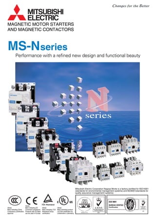
 (Note) Mark indicating China Compulsory Certification approval. (Note) Mark indicating EC Command compliance. Products with CE Mark can be used in Europe. (Note) Mark indicating TUV Rheinland Group certification. (Note) Mark indicating product UL/CSA certification by Underwriter’s Laboratory. MAGNETIC MOTOR STARTERS AND MAGNETIC CONTACTORS seriesseries
  • 2. Incorporation of CAN terminal for simple wiring Unified design for N series The design has been unified for the MS-N series. The front face of the product is a bright white color, making the inside of the panel brighter and providing a clean image. Arc space reduced to approx. one-third! By adopting the new extinguishing mechanism, the arc space has been reduced to approx. 1/3 (Mitsubishi comparison). Compatible with International Standards Most of Mitsubishi's standard products comply with International Standards. Applicable standards: JIS, JEM, IEC, EN, VDE, BS Approved standards: UL, CSA, LR, BV, NK, KR, TÜV, GB By adopting a CAN terminal, there is no need to remove the screws, and losing of the terminal screw is prevented by the integrated screw holder and terminal screw. The terminal screw is set in a plastic screw holder. When each pole is moved and the screw loosened, the screw is naturally set in the screw holder. This is Mitsubishi's original CAN terminal. (Patented) (S-N10CX~N35CX, SD-N11CX~N35CX, SR/SRD-N4CX) Substantial safety and functionality realized with a full lineup
  • 3. Simple inspections The contactor can be inspected easily by removing the arc cover. Built-in surge absorber The model with built-in surge absorber for coils is obtainable as an option. Pull up the screw holder. Insert the closed eyelet connector, and push up the screw holder. Tighten the screw. Stronger barrier strength is improved with the thermoplastic mold. Improved magnet By using a spiral kick-out spring, the dynamic balance of the moving parts is improved, bouncing is reduced, and the core life is extended. Furthermore, the core movement is generally stabilized. The efficient magnet has been achieved through modern technology of the magnet section using a computer. The contactor has a performance to withstand a voltage drop to 35% with the closed contact. Spiral kick-out spring Coil Moving core Stationary core Small-Sized Models S-N10~N35 15mm 15mm 15mm 15mm 15mm 38.5mm Indication of absorber Surge absorber Simple installation and wiring The MS-N series contactors, starters and relays can be installed on a mounting rail (35mm width). The terminals of these coils are arranged on the contactor with simple wiring. Furthermore, the distance between the center of the rail and the coil terminals is unified at 38.5mm. (S-N10 to N21, MSO-N10 to N21 and SR-N4) CAN terminal realizes safety and speedy The models with finger protection are safer and speedier even if the lug of a closed type eyelet (ring) terminal plate is used. (S-N10CX~N35CX, SD-N11CX~N35CX, SR/SRD-N4CX)
  • 4. Medium-and Large-Sized Models: S-N50~S-N800 DC Electromagnet with AC Operation (Patented) Even Greater Contact Reliability MATCH WITH ELECTRONIC CONTROL FOR FACTORY AUTOMATION If the magnetic relay coil is opened and closed near an electronic circuit, malfunctioning of the electronic circuit could be induced by a surge voltage. The UN-SA type surge absorber suppresses the surge voltage when this coil is opened and closed. In addition to the general varistor type and the CR type that lays importance on suppressing the induction voltage when starting, the type with operating indicator (varistor type), and the varistor type with CR are available. One-touch surge absorber An easy-to-install terminal cover, which lays importance on further safety and is compatible with finger protection, has been prepared. Finger Protection Compatible A new extinguishing structure, which eliminates the blow off of hot gas (arc) to the front (direction to door of control panel) when the current is cutoff has been incorporated. In addition to improved safety, the freedom of panel design has been increased allowing space to be saved. The arc blowoff direction has been changed to further improve safety and space conservation This is an auxiliary contact unit with low level contact, capable of opening and closing the low voltage and minute current of the electronic control circuit. It can be installed with one touch onto the magnetic contactor or magnetic relay that opens and closes the power of the motor, etc. The junction relay for opening and closing the low voltage and minute current is not needed, so this unit is suitable for opening and closing electronic input circuits in programmable logic controllers, etc. A compact microswitch is used for the low level contact, so the unit will not malfunction due to fields and surge voltages from the main circuit current and coil of the magnetic contactor. A 1NO+1NC low level contacts and 1NO+1NC standard contacts are built-in, so the opening and closing of 200VAC and 24VDC can be handled with one unit. Auxiliary contact unit with low level contact S2 types of inputs The long life no-contact output type (UN-SY21, SY31) and contact output type (UN-SY22, SY32) are available. SOne touch installation The UN-SY21, SY22, SY31 and SY32 types can be mounted with one touch onto the coil terminal. Post-installation work is easy. SSingle standalone unit A single unit installation type (UN-SY11, SY12) is available for the S-KR11 and S-N80 to N400 magnetic contactor. Interface unit Coil power consumption is greatly low so MS-N Series contactors can be controlled by almost any type of relay, even small output relays of programmable controllers. Lower Power Consumption When switching a coil, the energy will be desipated within internal circuit of electromagnet Contact reliability has been greatly improved by the bifurcated auxiliary moving contact Less Noise nor Surge from Coil The voltage rating ranges is widened and the coil type are reduced to one-third. Contactor Coils Have Ultra-Wide Range of Ratings DC excitation does not cause humming so operation is quiet. Internal circuit of the electromagnet Humming Completely Eliminated S-N 5 10 10 10 10 Frame N50/N65 N80/N95 N125~N220 N300/N400 N600/N800 S-K 10 10 30 50 10 Arc space(mm) Direct installation is possible on the following units: S-N series (Magnetic contactor) 65A frame or less SR-N series (Magnetic relay) 4-pole, 5-pole and 8-poles types C Coil R Contact spring Bifurcated moving contact Bifurcated moving contact Stationary contact Arc space
  • 5. TYPE REFERENCE LIST ........................................................................................................................................ 1 1. GENERAL PURPOSE CONTACTORS & STARTERS ........................................ Series MS-N 1.1 Conformity to International Standards ....................................................................................................... 2 1.1.1 List of Marked Type ............................................................................................................................. 3 1.1.2 TÜV Certified Type ................................................................................................................................... 3 1.1.3 UL Approval for U.S.A. and Canada ......................................................................................................... 5 1.1.4 CCC Certified Products ............................................................................................................................ 7 1.1.5 Approved Marine Standards ................................................................................................................... 11 1.2 Selection Guide ........................................................................................................................................... 12 1.3 The Overview (Type designation breakdown).......................................................................................... 14 1.3.1 Non-Reversing Types ............................................................................................................................. 14 1.3.2 Reversing Type....................................................................................................................................... 15 1.4 Technical Data of Series S-N Contactors ................................................................................................. 16 1.4.1 Ratings and Characteristics .................................................................................................................... 16 1.4.2 Performance of Series S-N Contactors .................................................................................................. 18 1.4.3 Mounting Attitude of Starters and Contactors ......................................................................................... 18 1.5 When Ordering ............................................................................................................................................ 19 1.6 Selection Table of Contactors ................................................................................................................... 20 1.6.1 Non-Reversing Contactors ............................................. Type S-N , SD-N ......................................... 20 1.6.2 Reversing Contactors ..................................................... Type S-2xN , SD-2xNN .............................. 21 1.6.3 Non-Reversing Mechanically Latched Contactors .......... Type SL-N , SLD-NN .................................. 22 1.6.4 Reversing Mechanically Latched Contactors.................. Type SL-2xN , SLD-2xN , SLxS-NN ............. 23 1.7 Selection Table of Direct-On-Line Motor Starters.................................................................................... 24 1.7.1 Non-Reversing Motor Starters without Enclosure(IP 00) Type MSO-N ................................................. 24 1.7.2 Reversing Motor Starters without Enclosure(IP 00)........ Type MSO-2xN ............................................. 25 1.7.3 Enclosed Non-Reversing Motor Starters(IP 20) ............. Type MS-N .................................................... 26 1.7.4 Enclosed Non-Reversing Motor Starters with Pushbutton Switch(IP 20) ............. Type MS-N PM ................. 27 1.8 Optional Parts and Accessories for Contactors ...................................................................................... 28 1.8.1 Replacement Coils.................................................................................................................................. 28 1.8.2 Replacement Contact Kits ...................................................................................................................... 28 1.8.3 Auxiliary Contact Blocks ......................................................................................................................... 29 1.8.4 Mechanical Interlocks ............................................................................................................................. 29 1.8.5 Connecting Bar Kits ................................................................................................................................ 29 1.8.6 Surge Absorbers ..................................................................................................................................... 30 1.8.7 Terminal Covers ..................................................................................................................................... 30 1.8.8 Pneumatic Time Delay Modules ............................................................................................................. 30 1.8.9 DC Interface Modules ............................................................................................................................. 30 1.9 Connections and Contact Arrangement ................................................................................................... 31 1.9.1 S, SD-N...................................................................................................................................................31 1.9.2 S, SD-2xN ............................................................................................................................................... 32 1.9.3 SL, SLD-(2x)N ........................................................................................................................................ 33 1.9.4 MSO-(2x)N.............................................................................................................................................. 34 1.9.5 MS-N....................................................................................................................................................... 35 1.9.6 MS-N PM .............................................................................................................................................. 35 1.10 Outline Dimensions .................................................................................................................................. 36 1.10.1 Outline Dimensions of Non-Reversing Contactors ............................................................................... 36 1.10.2 Outline Dimensions of Reversing Contactors ....................................................................................... 37 1.10.3 Outline Dimensions of Open Type Starters .......................................................................................... 38 1.10.4 Outline Dimensions of Enclosed Motor Starters ................................................................................... 39 CONTENTS
  • 6. 2. MOTOR PROTECTION RELAYS 2.1 Thermal Overload Relays ............................................................................. Series TH-N ........................ 40 2.1.1 Selection Guide of Thermal Overload Relays......................................................................................... 41 2.1.2 Selection Guide of the Current Transformers for TH-N600KP ............................................................... 42 2.1.3 Technical Data ........................................................................................................................................ 42 2.1.4 Selection Guide of Quick Trip Thermal Overload Relay ......................................................................... 42 2.1.5 Operating Characteristics of Thermal Overload Relays ......................................................................... 43 (Connecting wire size : Refer to “standard wire size” of Table 2.1.3) 2.1.6 Optional Parts and Accessories.............................................................................................................. 44 2.1.7 Outline Dimensions................................................................................................................................. 45 2.2 Electronic Motor Protection Relays ............................................................ Series ET-N ........................ 46 3. DEFINITE PURPOSE CONTACTORS & STARTERS 3.1 DC Contactors ............................................................................................... Series DU-K/A .................... 49 3.2 Medium Voltage Vacuum Contactors ......................................................... Series SH-V ........................ 52 3.3 Compact 3-Pole Contactors ......................................................................... Series S-N 8 .................... 55 3.4 NC Main Contact Contactors ....................................................................... Series B-N .......................... 56 3.5 Delay Open Type Magnetic Starters & Contactors .................................... Series S/MSO-N DL ........ 58 3.6 DC Interface Contactors ............................................................................... Series SD-Q ....................... 60 3.7 DC Interface Modules ................................................................................... Series UN-SY ..................... 63 4. RELAYS 4.1 Contactor Relays .......................................................................................... Series SR-N ........................ 65 4.1.1 Specifications.......................................................................................................................................... 66 4.1.2 Auxiliary Contact Blocks ......................................................................................................................... 67 4.1.3 Contact Arrangements of Contactor Relay ............................................................................................. 68 4.1.4 Spare Coils & Accessories ..................................................................................................................... 68 4.1.5 Outline Dimensions................................................................................................................................. 68 4.2 Voltage Detection Relays ............................................................................. Series SRE ......................... 69 4.3 Re-Starting Relays ........................................................................................ Series UA-DL ..................... 71 4.4 Solid State Time Delay Relays ..................................................................... Series SRS-H ..................... 73 4.5 Pneumatic Time Delay Relays ..................................................................... Series SRT-N ..................... 74 5. STAR-DELTA STARTERS ................................................................................... Series EYD-N 5.1 Selection Table............................................................................................................................................ 76 5.2 Specifications.............................................................................................................................................. 77 5.3 Outline Dimensions .................................................................................................................................... 78 5.3.1 Open Type (EYDO-N)............................................................................................................................. 78 5.3.2 Enclosed Type (EYD-N) ......................................................................................................................... 78 6. SOLID STATE CONTACTORS ............................................................................ Series US-N/K, H 6.1 Features ....................................................................................................................................................... 79 6.2 Product Scope............................................................................................................................................. 80
  • 7. 1 TYPE REFERENCE LIST DescriptionType NC main contact contactors ............................................................................................56 DC contactors..................................................................................................................49 Electronic motor protection relays ...................................................................................46 Star-delta starters ............................................................................................................76 General purpose enclosed type motor starters ...............................................................26 Enclosed non-reversing motor starters with pushbutton switch ......................................27 General purpose open type motor starters......................................................................14,24,38 Delay open type magnetic contactors .............................................................................58 General purpose open and reversing type motor starters ...............................................15,25,38 Plug-in sockets for,UA-DL2 .............................................................................................72 Compact 3-pole contactors .............................................................................................55 General purpose contactors ............................................................................................2~ DC interface contactors ...................................................................................................60 Delay open type magnetic contactors .............................................................................58 General purpose reversing contactors ............................................................................32 Medium voltage vacuum contactors ................................................................................52 Medium voltage reversing vacuum contactors ................................................................52 Mechanically latched contactors .....................................................................................22 Mechanically latched reversing contactors......................................................................23 Mechanically latched and normal reversing contactors...................................................23 Contactor relays ..............................................................................................................65 Voltage detection relays ..................................................................................................69 Solid state time delay relays............................................................................................73 Pneumatic time delay relays ...........................................................................................74 Thermal overload relays ..................................................................................................40 Saturable reactors for TH-N ............................................................................................44 Auxiliary contact blocks for SH-V ....................................................................................54 Re-starting relay ..............................................................................................................71 Surge absorbers for SH-V ...............................................................................................53 Auxiliary contact blocks ...................................................................................................29,50,67 Mechanical interlocks for S-N..........................................................................................29 Reset release for TH-N ...................................................................................................44 Surge absorbers for S-N and SR-N4...............................................................................30 DC interface modules for S-N .........................................................................................30,63 Trip indicator for TH-N .....................................................................................................44 Pneumatic time delay modules .......................................................................................30,78 Solid State Contactors.....................................................................................................79 Solid State Contactors.....................................................................................................79 Ref.Page B(D)-N DU(D)- ET-N EYD(O)-N MS-N MS-N PM MSO(D)-N MSO-N DL MSO(D)-2XN PF- S-N 8 S(D)-N SD-Q S-N DL S(D)-2XN SH(L)(D)-V SH(L)(D)-2XV SL(D)-N SL(D)-2XN SLXS-N SR(D)-N SRE- SRS-H SRT(D)-N TH-N THR- UA-AXVV UA-DL2 UA-SU UN-AX UN-ML UN-RR UN-SA UN-SY UN-TL UN-TR US-N /K US-H
  • 8. 2 1. GENERAL PURPOSE CONTACTORS & STARTERS 1.1 Conformity to International Standards Series MS-N Mitsubishi magnetic motor starters and contactors are designed to conform to the relevant IEC recommendations and to the standards of as many countries as possible. Specifically, they conform to the following: VDE0660 NEMA-ICS IEC60947-4-1 EN60947-4-1 International Europe Germany U.S.A Table 1.1 DC Operated Contactor Overload Relay AC Operated Contactor Type (✽2) Canada U.K. France Korea Japan Lloyd’s Register of Shipping Korean Register of Shipping Bureau Veritas Nippon Kaiji Kyokai AC Operated Contactor Relay DC Operated Contactor Relay Auxiliary Contact Block U.S.ACanadaU.S.A Listing Recognition Europe North America / UL TÜVCE Mark ᭺ — — — — — ● (✽2) ᭺ (✽2) ● (✽2) ᭺ — ᭺ —— ᭺ ᭺ ᭺ ᭺ ᭺ ᭺ ✩ — — ᭺ ᭺ ᭺ ᭺ ᭺ ᭺ ᭺ ᭺ — — — — — — — — — — ᭺ — — ᭺ Marine ( Mark) ( Mark) ( Mark) ( Mark) ( Mark) ( Mark) — ᭺ (✽2) ✩ ( Mark) ( Mark) ( Mark) (✽2) Model Name SR-N4(CX) SRD-N4(CX) UN-AX2(CX) UN-AX4(CX) UN-AX11(CX) UN-AX80 UN-AX150 S-N10(CX) S-N11(CX)/N12(CX) S-N18(CX) S-N20(CX)/N21(CX) S-N25(CX) S-N35(CX) S-N28(CX) S-N38(CX) S-N48(CX) S-N50 S-N65 S-N80 S-N95 S-N125 S-N150 S-N180 S-N220 S-N300 S-N400 S-N600 S-N800 TH-N12(CX)KP TH-N18(CX)KP TH-N20(TA)(CX)KP TH-N60(TA)KP TH-N120(TA)KP TH-N220RHKP/HZKP TH-N400RHKP/HZKP SD-N11(CX)/N12(CX) SD-N21(CX) SD-N35(CX) SD-N50 SD-N65 SD-N80 SD-N95 SD-N125 SD-N150 SD-N220 SD-N300 SD-N400 SD-N600 SD-N800 China CCC certification — Notes:1. : CE Mark (Manufacturer’s Declaration) == Standard model applicable, marking on the product. UL, TÜV, CCC == Standard model applicable, marking on the product. NK == Standard model applicable, Certificate No. on the product. ● : Standard model applicable, no marking on the product. If marking required, order model name followed by suffix “DZ”. ᭺ : Standard model applicable, no marking on the product. ✩ : Special model applicable, marking on the product. Order model name followed by suffix “UL”. ★ : China export applicable, no marking on the product. Ensure to add “CN” after the model name when placing an order. — : Not applicable to the Standard or not approved. 2. Finger protection type is certified according to DIN VDE 0106 part 100. For finger protection type, order model name followed by suffix “CX”. 3. For each certificate conditions, see next three pages. ★ ★ ★
  • 9. 3 Notes:1. Listed types are representatives and containes standard models. 2. Applicable product standards Contactors : EN60947-1, EN60947-4-1, EN60947-5-1 Thermal overload relays : EN60947-1, EN60947-4-1, EN60947-5-1 Aux. contact blocks : EN60947-1, EN60947-5-1 Mechanical interlocks : EN60947-1, EN60947-4-1, EN60947-5-1 3. For mechanical interlocks, no marking on the product. Mechanical interlocks are applicable when used in reversing contactors. 4. Necessary to connect a varistor etc., in order to provide compliance for CE marking for the US-N5/N8SS(TE)and US-N(H) 70/N(H) 80NS(TE) type. 1.1.1 List of Marked Type Standard Contactors Non-reversing A.C. operated D.C. operated A.C. operated D.C. operated Additional Auxiliary Contact Blocks Standard Contactors Reversing Mechanical Interlocks3 S-N10, S-N11, S-N12, S-N18, S-N20, S-N21, S-N25, S-N28, S-N35, S-N38, S-N48, S-N50, S-N65, S-N80, S-N95, S-N125, S-N150, S-N180, S-N220, S-N300, S-N400, S-N600, S-N800 SD-N11, SD-N12, SD-N21, SD-N35, SD-N50, SD-N65, SD-N80, SD-N95, SD-N125, SD-N150, SD-N220, SD-N300, SD-N400, SD-N600, SD-N800 S-2XN10, S-2XN11, S-2XN20, S-2XN21, S-2XN25, S-2XN35, S-2XN50, S-2XN65, S-2XN80, S-2XN95, S-2XN125, S-2XN150, S-2XN180, S-2XN220, S-2XN300, S-2XN400, S-2XN600, S-2XN800 SD-2XN11, SD-2XN21, SD-2XN35, SD-2XN50, SD-2XN65, SD-2XN80, SD-2XN95, SD-2XN125, SD-2XN150, SD-2XN220, SD-2XN300, SD-2XN400, SD-2XN600, SD-2XN800 UN-AX2, UN-AX4, UN-AX11, UN-AX80, UN-AX150, UQ-AX2(KR) UN-ML11, UN-ML21, UN-ML80, UN-ML150, UN-ML220 Thermal Overload Relays TH-N12KP, TH-N18KP, TH-N20KP, TH-N20TAKP, TH-N60KP, TH-N60TAKP, TH-N120KP, TH-N120TAKP, TH-N220RHKP, TH-N220HZKP, TH-N400RHKP, TH-N400HZKP, TH-N600KP Contactor Relays A.C. operated D.C. operated D.C. Interface Contactors Non-reversing Reversing SR-N4 SRD-N4 SD-Q11, SD-Q12, SD-Q19 SD-QR11, SD-QR12, SD-QR19 Table 1.1.1 Solid state Contactors (for motor/heater load) Solid state Contactors (for heater load) US-N5SS(TE), US-N8SS(TE), US-N20(TE), US-N30(TE), US-N40(TE), US-N50(TE), US-N70NS(TE), US-N80NS(TE), US-NH70NS(TE), US-NH80NS(TE), US-N20(TE)CX, US-N30(TE)CX, US-N40(TE)CX, US-N20(TE)RM US-H20(DD), US-H30(DD), US-H40(DD), US-H50(DD), US-H20(DD)RM, US-H30(DD)RM Notes:1. Standard models are applicable under following conditions. Main circuits : AC-3 rated current at 440V AC max. (Main contacts) and rated continuous current. Auxiliary contacts : AC-15 rated current at 550V AC max. and rated continuous current. Operation coil : AC coil designation N10~N12, N18~N48 and SR-N4 ; AC12V~AC440V N20~N35 ; AC12V~AC380V N50~N150 ; AC24V~AC500V N180~N400 ; AC48V~AC500V DC coil designation DC12V~DC220V 2. For contactors, standard models are with TÜV mark on the product. For other products, standard models are with no TÜV mark on the product. 3. Finger protection type is certified according to DIN VDE 0106 part 100. For finger protection type, order model name followed by suffix “CX”. 4. Models with built-in surge absorber (model name followed by “SA”) are also certified. 5. Mirror contact function compliance certification has been obtained from TÜV. This product is suitable for use in a machine tool's interlock circuit. The mirror contact function refers to a function in which the auxiliary NC contact can withstand a 2500V impulse voltage without contacting even if the main contact melts. 1.1.2 TÜV Certified Type ■ Contactor Table 1.1.2 (1) S-N10(CX)(SA) S-N11(CX)(SA) S-N12(CX)(SA) S-N20(CX)(SA) S-N21(CX)(SA) S-N25(CX)(SA) S-N35(CX)(SA) S-N18(CX)(SA) S-N28(CX)(SA) S-N38(CX)(SA) S-N48(CX)(SA) S-N50/S-N65 S-N80/S-N95 S-N125 S-N150 S-N180/S-N220 S-N300/S-N400 SD-N11(CX)(SA) SD-N12(CX)(SA) SD-N21(CX)(SA) SD-N35(CX)(SA) SD-N50/SD-N65 SD-N80/SD-N95 SD-N125 SD-N150 SD-N220 SD-N300/SD-N400 Model Name Certificate No. EN60947-4-1 R9551340 Applicable standard Mirror contact5 Internal auxiliary NC contact Auxiliary contact block Auxiliary NC contact EN60947-4-1 EN60947-4-1 EN60947-4-1 EN60947-4-1 EN60947-4-1 EN60947-4-1 EN60947-4-1 EN60947-4-1 EN60947-4-1 EN60947-4-1 EN60947-4-1 EN60947-4-1 EN60947-4-1 EN60947-4-1 EN60947-4-1 EN60947-4-1 EN60947-4-1 R9651190 R9651189 R9851170 R9851138 R9851169 R9851167 R9851164 R9851171 R9551336 R9651190 R9851170 R9851138 R9851169 R9851167 R9851164 R9851171 R9551340 ᭺ — ᭺ ᭺ ᭺ ᭺ ᭺ ᭺ — — ᭺ (UN-AX2(CX), UN-AX4(CX)) ᭺ (UN-AX2(CX), UN-AX4(CX)) — ᭺ (UN-AX150) ᭺ (UN-AX2(CX), UN-AX4(CX)) ᭺ (UN-AX150) EN60947-4-1 R9551336 Solid state Contactors : EN60947-4-2, EN60947-4-3 (for motor/heater load) Solid state Contactors : EN60947-4-3 (for heater load)
  • 10. 4 Notes:1. Standard models are applicable under following conditions. Main circuits : AC-3 rated current at 440V AC max. (Main contacts) and rated continuous current. Auxiliary contacts : AC-15 rated current at 550V AC max. (SD-Q(R)11~Q(R)19 : 440V AC max.) and rated continuous current. Operation coil : AC coil designation SR-N4 ; AC12V~AC440V DC coil designation DC12V~DC220V (SD-Q(R)11~Q(R)19 : DC12V~DC24V) 2. For contactors, standard models are with TÜV mark on the product. For other products, standard models are with no TÜV mark on the product. For contactor relays, order model name followed by suffix “DZ” if TÜV mark on the product is required. 3. Finger protection type is certified according to DIN VDE 0106 part 100. For finger protection type, order model name followed by suffix “CX”. 4. Models with built-in surge absorber (model name followed by “SA”) are also certified. 5. Miller contact function compliance certification has been obtained from TÜV. This product is suitable for use in a machine tool's interlock circuit. The miller contact function refers to a function in which the auxiliary NC contact can withstand a 2500V impulse voltage without contacting even if the main contact melts. 6. If the SD-Q11 with 1NC is required, it must be so indicated when placing an order. ■ Thermal Overload Relay TH-N12(CX)KP TH-N18(CX)KP TH-N20(TA)(CX)KP TH-N60(TA)KP TH-N120(TA)KP TH-N220RHKP/HZKP TH-N400RHKP/HZKP Model Name Applicable standard Registration No. EN60947-4-1 EN60947-4-1 EN60947-4-1 EN60947-4-1 EN60947-4-1 EN60947-4-1 EN60947-4-1 J9551338 J9551338 J9551341 J9851140 J9851168 J9851166 J9851172 Table 1.1.2 (3)■ DC Interface Contactor SD-Q11 SD-Q12 SD-Q19 SD-QR11 SD-QR12 SD-QR19 Model Name Certificate No. Miller contact5 R2-50004919 R2-50004919 R2-50004918 R2-50004919 R2-50004919 R2-50004918 ᭺ — — — — — Table 1.1.2 (2) Internal auxiliary NC contact Auxiliary contact block Auxiliary NC contact ᭺ ᭺ ᭺ — — — 6 (UQ-AX2) ■ Contactor Relay SR-N4(CX)(SA) SRD-N4(CX)(SA) Model Name Applicable standard Certificate No. EN60947-5-1 EN60947-5-1 R9551339 R9551339 Table 1.1.2 (4) ■ Auxiliary Contact Block UN-AX2(CX) UN-AX4(CX) UN-AX11(CX) UN-AX80 UN-AX150 Model Name Applicable standard Registration No. EN60947-5-1 J9551337 EN60947-5-1 R9851225 Table 1.1.2 (5) ■ Solid state contactor (for motor/heater lord) Table 1.1.2 (6) Standard Finger protected Mounting on 35mm rail Certificate No. US-ᮀ US-ᮀCX US-ᮀRM R50037627 R50037628 R50037629 R50037630 – R50037628 – – R50037628 – – Model Name US-N5SS(TE) US-N8SS(TE) US-N20(TE) US-N30(TE) US-N40(TE) US-N50(TE) US-N70NS(TE) US-N80NS(TE) US-NH70NS(TE) US-NH80NS(TE) Approval rating (A) Heater (AC-51) Motor (AC-53) AC100-240V AC200-440V AC200-240V AC400-440V 5 8 20 30 40 50(45) 70 80 – – 3 4.8 12 18 24 30(27) 42 48 – – – – 20 30 40 50(45) – – 65 75 – – 12 18 24 30(27) – – 39 45 3.2 3.2 11.1 17.4 26 26 48 48 48 48 – – 11.1 17.4 26 26 – – 48 48 40C° 60C° 40C° 60C° 40C° 40C° Applicable standard Motor: EN60947-4-2 Heater: EN60947-4-3 ■ Solid state contactor (for heater lord) Table 1.1.2 (7) Standard No cooling fin Mounting on 35mm rail Certificate No. US-ᮀ US-ᮀHZ US-ᮀRM R50018958 R50018958 R50018958 – Model Name US-H20(DD) US-H30(DD) US-H40(DD) US-H50(DD) Approval rating (A) Heater (AC-51) AC24-480V 20 30 40 50 12 18 24 30 40C° 60C° Applicable standard Heater : EN60947-4-3 Notes: 1. The number in the type field indicates the certificate number, and hyphen “-” indicates that there are no compatible models. 2. The value in the certified rating field in the bracket “( )” indicates the rating for US-N50TE. 3. The frame field “(TE)” indicates 3-pole, 3-element type main circuit. 4. Standard models are with TÜV mark on the product. Notes: 1. The number in the type field indicates the certificate number, and hyphen “-” indicates that there are no compatible models. 2. The frame field “(DD)” indicates 3-pole individual control. 3. Standard models are with TÜV mark on the product.
  • 11. 5 S-N800UR2 910 — — 250 300 600 600 — — — — — — 12004 – S(D)-N11(CX) S(D)-N12(CX) 20 1/2 1-1/2 3 3 7-1/2 7-1/2 MSO- N11KP(CX) N12KP(CX) 3 3 7-1/2 7-1/2 30 – S-N10(CX) 13 1/2 1-1/2 3 3 5 5 MSO- N10KP(CX) 3 3 5 5 30 – A 120V HP 240V HP 208V HP 240V HP 480V HP 600V HP 208V HP 240V HP 480V HP 600V HP A A Conta- ctor (open) Starter (open) Max. rating of short circuit protection device Fuse class K5 Circuit breaker S-N18(CX) 30 1 3 5 5 10 10 MSO- N18KP(CX) 5 5 10 10 70 – S-N20(CX) S(D)-N21(CX) 30 1 3 5 5 10 10 MSO- N20KP(CX) N21KP(CX) 5 5 10 10 70 – S-N25(CX) 35 2 3 7-1/2 7-1/2 15 15 MSO- N25KP(CX) 7-1/2 7-1/2 15 15 100 100 S(D)-N35(CX) 40 2 5 10 10 20 20 MSO- N35KP(CX) 10 10 20 20 125 125 S(D)-N50 80 3 7-1/2 15 15 30 30 MSO- N50KP 15 15 30 30 250 — S(D)-N65 95 3 10 15 20 40 40 MSO- N65KP 15 20 40 40 250 — S(D)-N80 100 5 15 20 25 50 50 MSO- N80KP 20 25 50 50 300 300 S(D)-N1252 125 10 20 40 40 75 75 MSO- N125KP 2 40 40 75 75 350 350 S(D)-N952 100 7-1/2 15 25 30 60 60 MSO- N95KP 2 25 30 60 60 225 225 S(D)-N1502 150 15 25 40 50 100 100 MSO- N150KP 2 40 50 100 100 350 350 S-N1802 220 15 30 60 60 125 125 MSO- N180KP 2 60 60 125 125 500 500 S(D)-N2202 220 15 40 60 75 150 150 MSO- N220KP 2 60 75 150 150 500 500 S(D)-N3002 300 — — 100 100 200 200 MSO- N300KP 2 100 100 200 200 6003 600 S(D)-N4002 400 — — 125 150 300 300 MSO- N400KP 2 125 150 300 300 5003 1000 S-N6002 680 — — 150 200 400 400 — — — — — — 8004 – Notes: 1. UL listed types for S-N600 and S-N800 require suffix letters “UL” (eg. S-N800UL). 2. Types S-N95 to S-N800 and MSO-N95KP to N400KP with Ilsco lugs are also listed as type name with suffix letters “UL” (eg. S-N95UL) 3. Time delay fuse 4. Class L fuse 1.1.3 UL Approval for U.S.A. and Canada ■ Contactor and Motor Starter Model Name Continuous current rating open Horsepower rating Single phase Three phase Model Name Horsepower rating Three phase Mark Mark — Table 1.1.3 (1) Type Model Name MarkRatings UN-AX2(CX) UN-AX4(CX) UN-AX11(CX) UN-AX80 UN-AX150 SR-N4 SRD-N4 Contactor Relay Auxiliary Contact Block ■ Contactor Relay and Auxiliary Contact Block Table 1.1.3 (3) Rated Code; A600 AC600V max Make 7200VA Break 720VA Rated Code; R300 DC250V max Make 28VA Break 28VA ■ Thermal Overload Relay Table 1.1.3 (2) 0.12A(0.1~0.16),0.17(0.14~0.22),0.24A(0.2~0.32), 0.35A(0.28~0.42),0.5A(0.4~0.6),0.7A(0.55~0.85),0.9A(0.7~1.1), 1.3A(1~1.6),1.7A(1.4~2),2.1A(1.7~2.5),2.5A(2~3),3.6A(2.8~4.4), 5A(4~6),6.6A(5.2~8),9A(7~11),11A(9~13) Model Name TH-N12(CX)KP✩ TH-N12(CX)✩✽1 TH-N12(CX)HZKP★✽2 TH-N12(CX)HZ★✽1 TH-N18(CX)KP✩ TH-N18(CX)✩✽1 1.3A(1~1.6),1.7(1.4~2),2.1A(1.7~2.5),2.5A(2~3),3.6A(2.8~4.4), 5A(4~6),6.6A(5.2~8),9A(7~11),11A(9~13),15A(12~18) 0.24A(0.2~0.32),0.35A(0.28~0.42),0.5A(0.4~0.6), 0.7A(0.55~0.85),0.9A(0.7~1.1),1.3A(1~1.6),1.7A(1.4~2), 2.1A(1.7~2.5),2.5A(2~3),3.6A(2.8~4.4),5A(4~6),6.6A(5.2~8), 9A(7~11),11A(9~13),15A(12~18) TH-N20(CX)KP TH-N20(CX)✽1 TH-N20CXHZKP★ TH-N20CXHZ★✽1 TH-N20TAKP✩ TH-N20TA✩✽1 22A(18~26) 29A(24~34) TH-N60KP 15A(12~18),22A(18~26),29A(24~34),35A(30~40),42A(34~50) 54A(43~65) TH-N60TAKP✩ 67A(54~80) 82A(65~100) TH-N120KP 42A(34~50),54A(43~65),67A(54~80),82A(65~100) 105A(85~125) 125A(100~150) 82A(65~100),105A(85~125),125A(100~150),150A(120~180) 180A(140~220) TH-N220RHKP✩ TH-N220HZKP★ 105A(85~125),125A(100~150),150A(120~180),180A(140~220),250A(200~300) 330A(260~400) TH-N400RHKP✩ TH-N400HZKP★ Heater designation (Rated current [A]) Contactor to be coupled S-N10 S-N11 S-N12 S-N18 S-N20 S-N21 S-N25 S-N35 S-N25,N35 S-N35 S-N50,N65,N80,N95 S-N65,N80,N95 S-N80,N95 S-N95 S-N125,N150 S-N125,N150 S-N150 S-N180,N220 S-N220 S-N300,N400 S-N400 Auxiliary Contact Rated Code Make C600 AC600Vmax 1800VA(15A max) Break 180VA(1.5A max) Rated Code Make B600 AC600Vmax 3600VA(30A max) Break 360VA(3A max) / / TH-N120TAKP✩ Notes: 1. ✩ is to be coupled with contactor and can not be mounted separately from contactor. ★ is only for separate mounting. 2. Suffix “KP” ; Overload and phase failure protection type with three heater elements. 3. ✽1 ; TH-N12(CX), N12(CX)HZ, N18(CX), N20(CX), N20CXHZ and N20TA are recognized ( ) for single phase motors. 4. ✽2 is to be coupled with TH-N12(CX)KP ( ) and UN-HZ12( ).
  • 12. 6 ■ DC Interface Contactor Table 1.1.3 (4) SD-Q11 SD-Q12 MSOD-Q11(KP) MSOD-Q12(KP) SD-Q19 MSOD-Q19(KP) Model Name Continuous current rating [A] Horsepower rating [HP] Single-phase (only non-reversing type) three-phase Note: 1. MSOD-Q11, Q12 and Q19 are approved for single-phase circuits. Non-reversing type Reversing type SD-QR11 SD-QR12 MSOD-QR11KP MSOD-QR12KP SD-QR19 MSOD-QR19KP 110 ~ 120V 220 ~ 240V 200 ~ 208V 220 ~ 240V 440 ~ 480V 20 13 30 18 1 3 1 2 1 3 3 5 1 1 2 5 5 7 1 2 Model Name US-N5SS US-N8SS US-N20(CX)(RM) US-N30(CX) US-N40(CX) US-N50(CX) US-N70NS US-N80NS US-NH70NS US-NH80NS US-N5SSTE US-N8SSTE US-N20TE(CX)(RM) US-N30TE(CX) US-N40TE(CX) US-N50TE(CX) US-N70NSTE US-N80NSTE US-NH70NSTE US-NH80NSTE 1 2 2 3 3 3 3 15 15 15 15 3 53 3 3 – – 5 10 20 20 – – 30 30 5 8 20 30 40 50 70 80 70 80 100~120V 220~240V 220~240V 440~480V 3-pole,2-element type 3-pole,3-element type ■ Solid state contactor (for motor/heater load) Table 1.1.3 (5) Continuous current rating [A] 1 10 1 10 1 2 1 4 1 4 1 2 7 1 2 7 1 2 7 1 2 7 1 2 1 1 2 7 1 2 7 3 4 3 4 Single-phase three-phase Horsepower rating [HP] US-H20(RM)(HZ) US-H30(RM) US-H40 US-H50 US-H20DD(RM)(HZ) US-H30DD(RM) US-H40DD US-H50DD 20 30 40 50 ■ Solid state contactor (for heater load) Table 1.1.3 (6) Continuous current rating [A] Model Name Batch control Individual control Notes: 1. “(HZ)” has no cooling fin. “(RM)” is available rail mounting. 2. The US-Hᮀ (DD) HZ type is certified at the continuous current rating when combined with the fin used on the US-Hᮀ (DD) type. 3. The US-Hᮀ (DD) HZ type is UR certified.
  • 13. 7 1.1.4 CCC Certified Products Magnetic motor starters, etc., are designated as products targeted for China Compulsory Certification. CCC certification must be acquired before the product is exported to main land China from Domestic or marketed in China. The certified models are shown in Tables 1.1.4 (1-1) to 1.1.4 (8-2). The option units (UN-CV, ML, RR, SA, etc.) which are mounted on the magnetic motor starter and which do not have a load switching function are excluded from the CCC certification target. Model Name MSO-(2✕)N10✽✽ MSO(D)-(2✕)N11✽✽ MSO(D)-N12✽✽ MSO-(2✕)N18✽✽ MSO-(2✕)N20✽✽ MSO(D)-(2✕)N21✽✽ MSO-(2✕)N25✽✽ MSO(D)-(2✕)N35✽✽ MSO(D)-(2✕)N50KP✽✽ MSO(D)-(2✕)N65KP✽✽ MSO(D)-(2✕)N80KP✽✽ MSO(D)-(2✕)N95KP✽✽ MSO(D)-(2✕)N125KP✽✽ MSO(D)-(2✕)N150KP✽✽ MSO-(2✕)N180KP✽✽ MSO(D)-(2✕)N220KP✽✽ MSO(D)-(2✕)N300KP✽✽ MSO(D)-(2✕)N400KP✽✽ 2.5/4 3.5/5.5 3.5/5.5 4.5/7.5 5.5/11 5.5/11 7.5/15 11/18.5 15/22 18.5/30 22/45 30/55 37/60 45/75 55/90 75/132 90/160 125/220 Approval rating AC-3 Class (200~240V/380~440V) Heater designation Coil designation AC operated (MSO type) DC operated (MSOD type)Rated capacity (kW) 11/9 13/12 13/12 18/16 22/22 22/22 30/30 40/40 55/50 65/65 85/85 105/105 125/120 150/150 180/180 250/250 300/300 400/400 0.12-9A 0.12-11A 0.12-11A 0.12-15A 0.24-19A 0.24-19A 0.24-22A 0.24-35A 15-42A 15-54A 15-67A 15-95A 42-105A 42-125A 82-150A 82-210A 105-250A 105-330A AC12V~AC500V DC12V~DC220V AC24V~AC500V DC12V~DC220V AC48V~AC500V DC12V~DC220V CX, KP, SA, SR CX, SA CX, KP, SA, SR CX, SR SR Certificate No. Type ✽✽ application range (combination possible) Number of aux. contacts Non-reversing Standard (special) 20020103 04093078 20020103 04093077 20020103 04093076 20020103 04093073 20020103 04093064 20020103 04093067 20020103 04093079 20020103 04093070 20020103 04093066 1NO(1NC) 1NO(1NC) 1NO1NC(2NO) – 1NO1NC(2NO) 2NO2NC 2NO2NC 2NO2NC 2NO2NC 2NO2NC 2NO2NC 2NO2NC 2NO2NC 2NO2NC 2NO2NC 2NO2NC 2NO2NC 2NO2NC Rated operational current (A) MSO : AC operated MSOD : DC operated 2✕ : Reversing type Table 1.1.4 (1-2) Notes: 1. The MSO-(2×) N10KP, MSO(D)-(2×)N11KP or MSO(D)-N12KP type with heater designation 0.12A and 0.17A are not certified. 2. MSO-(2×)N18KP type is not certified. Model Name MS-N10CN✽✽ MS-N11CN✽✽ MS-N12CN✽✽ MS-N20CN✽✽ MS-N21CN✽✽ MS-N25CN✽✽ MS-N35CN✽✽ MS-N50CNKP✽✽ MS-N65CNKP✽✽ MS-N80CNKP✽✽ MS-N95CNKP✽✽ MS-N125CNKP MS-N150CNKP MS-N180CNKP MS-N220CNKP MS-N300CNKP MS-N400CNKP 2.5/4 3.5/5.5 3.5/5.5 5.5/11 5.5/11 7.5/15 11/18.5 15/22 18.5/30 22/45 30/55 37/60 45/75 55/90 75/132 90/160 125/220 Approval rating AC-3 Class (200~240V/380~440V) Heater designation Coil designation AC operatedRated capacity (kW) 11/9 13/12 13/12 22/22 22/22 30/30 40/40 55/50 65/65 85/85 105/105 125/120 150/150 180/180 250/250 300/300 400/400 0.12~9A 0.12~11A 0.12~11A 0.24~19A 0.24~19A 0.24~22A 0.24~35A 15~54A 15~54A 15~67A 15~95A 42~105A 42~125A 82~150A 82~210A 105~250A 105~330A AC12V~AC500V AC24V~AC500V AC48V~AC500V KP, SA, PM KP, SA, PM PM – Certificate No. Type ✽✽ application range (combination possible) Number of aux. contacts Non-reversing Standard (special) 20030103 04093078 20030103 04093077 20030103 04093076 20030103 04093073 20030103 04093064 20030103 04093067 20030103 04093079 20030103 04093070 20030103 04093066 1NO 1NO 1NO1NC(2NO) 1NO1NC(2NO) 2NO2NC 2NO2NC 2NO2NC 2NO2NC 2NO2NC 2NO2NC 2NO2NC 2NO2NC 2NO2NC 2NO2NC 2NO2NC 2NO2NC 2NO2NC Rated operational current (A) ■ Magnetic motor starter MS : AC operated Table 1.1.4 (1-1)• With Enclosure • Without Enclosure
  • 14. 8 Model Name S-(2✕)N10✽✽ S(D)-(2✕)N11✽✽ S(D)-N12✽✽ S-(2✕)N18✽✽ S-(2✕)N20✽✽ S(D)-(2✕)N21✽✽ S-(2✕)N25✽✽ S(D)-(2✕)N35✽✽ S(D)-(2✕)N50✽✽ S(D)-(2✕)N65✽✽ S(D)-(2✕)N80 S(D)-(2✕)N95 S(D)-(2✕)N125 S(D)-(2✕)N150 S-(2✕)N180 S(D)-(2✕)N220 S(D)-(2✕)N300 S(D)-(2✕)N400 S(D)-(2✕)N600CN S(D)-(2✕)N800CN 2.5/4 3.5/5.5 3.5/5.5 4.5/7.5 5.5/11 5.5/11 7.5/15 11/18.5 15/22 18.5/30 22/45 30/55 37/60 45/75 55/90 75/132 90/160 125/220 190/330 220/440 Approval rating AC-3 Class (200~240V/380~440V) Conventional free air thermal current Ith (A) Coil designation AC operated (S type) DC operated (SD type)Rated capacity (kW) 11/9 13/12 13/12 18/16 22/22 22/22 30/30 40/40 55/50 65/65 85/85 105/105 125/120 150/150 180/180 250/250 300/300 400/400 630/630 800/800 20 20 20 25 32 32 50 60 80 100 135 150 150 200 260 260 350 450 660 800 AC12V~AC500V DC12V~DC220V AC24V~AC500V DC12V~DC220V AC48V~AC500V DC12V~DC220V AC100V~AC500V DC24V~DC220V CX, SA CX – – Certificate No. Type ✽✽ application range (combination possible) Number of aux. contacts Non-reversing Standard (special) 20020103 04023375 20020103 04023377 20020103 04024684 20020103 04024704 20020103 04024705 20020103 04024706 20020103 04024707 20020103 04024708 20020103 04024709 20030103 04095569 1NO (1NC) 1NO (1NC) 1NO1NC(2NO) – 1NO1NC (2NO) 2NO2NC 2NO2NC 2NO2NC 2NO2NC 2NO2NC 2NO2NC 2NO2NC 2NO2NC 2NO2NC 2NO2NC 2NO2NC 2NO2NC 2NO2NC 2NO2NC 2NO2NC Rated operational current (A) ■ Magnetic Contactors S : AC operated SD : DC operated 2✕ : Reversing type Table 1.1.4 (2-1) Table 1.1.4 (2-2) Model Name SL(D)-(2✕)N21✽✽ SL(D)-(2✕)N35✽✽ SL(D)-(2✕)N50✽✽ SL(D)-(2✕)N65✽✽ SL(D)-(2✕)N80 SL(D)-(2✕)N95 SL(D)-(2✕)N125 SL(D)-(2✕)N150 SL(D)-(2✕)N220 SL(D)-(2✕)N300 SL(D)-(2✕)N400 SL(D)-(2✕)N600CN SL(D)-(2✕)N800CN 5.5/11 11/18.5 15/22 18.5/30 22/45 30/55 37/60 45/75 75/132 90/160 125/220 190/330 220/440 Approval rating AC-3 Class (200~240V/380~440V) Conventional free air thermal current Ith (A) Coil designation AC operated (SL type) DC operated (SLD type)Rated capacity (kW) 22/22 40/40 55/50 65/65 85/85 105/105 125/120 150/150 250/250 300/300 400/400 630/630 800/800 32 60 80 100 135 150 150 200 260 350 450 660 800 AC100V~AC500V DC12V~DC200V AC100V~AC500V DC24V~DC200V CX, SA CX – – Certificate No. Type ✽✽ application range (combination possible) Number of aux. contacts Non-reversing Standard 20020103 04023377 20020103 04024684 20020103 04024704 20020103 04024705 20020103 04024706 20020103 04024707 20020103 04024708 20020103 04024709 20030103 04095569 2NO2NC 2NO2NC 2NO2NC 2NO2NC 2NO2NC 2NO2NC 2NO2NC 2NO2NC 2NO2NC 2NO2NC 2NO2NC 1NO2NC Rated operational current (A) SL : AC operated SLD: DC operated 2✕ : Reversing type Table 1.1.4 (2-3) Model Name S-(2✕)N18✽✽ S-(2✕)N28✽✽ S-(2✕)N38✽✽ S-(2✕)N48✽✽ 4.5/7.5 7.5/7.5 11/15 15/18.5 Approval rating AC-3 Class (200~240V/380~440V) Conventional free air thermal current Ith (A) Coil designation AC operated (S type)Rated capacity (kW) 18/16 26/17 39/32 50/40 25 30 60 80 AC12V~AC500V CX, SA Certificate No. Type ✽✽ application range (combination possible) Number of aux. contacts Non-reversing Standard 20020103 04023377 20020103 04024684 – – – – Rated operational current (A) S : AC operated 2✕ : Reversing type Model Name B(D)-N20CN✽✽ B(D)-N65CN B(D)-N100CN DC110V 2P 3P DC220V 2P 3P DC110V 2P 3P DC220V 2P 3P DC110V 2P DC220V 2P B: 1NO2NC, 3NC BD: 1NO2NC B:1NO2NC BD:1NO2NC Certification ratings (A)Main contact Arrangement Conventional free air thermal current Ith (A) Coil designation AC operated (B type) DC operated (BD type) Number of series 8 15 1 5 20 50 3 20 30 3 25 80 120 AC24V~AC500V DC12V~DC220V SA – Number of aux. contacts Non-reversing 20020103 04023377 20020103 04024705 20020103 04024706 2NO 2NO2NC 2NO2NC NC DC-3,5 15 20 5 10 30 65 10 30 40 20 NC DC-1B : AC operated BD : DC operated Table 1.1.4 (2-4) Certificate No. Type ✽✽ application range (combination possible) • General Type Contactors • Mechanically Latched Contactors • 3-Pole Contactors • NC Main Contact Type Contactors
  • 15. 9 20020103 03024700 20020103 03024720 20020103 03024722 20020103 03024720 Model Name Certificate No. UN-AX2CN✽✽ UN-AX4CN✽✽ UN-AX11CN✽✽ UN-AX80CN UN-AX150CN UN-AX600CN UN-LL22CN✽✽ 2NO, 1NO1NC 4NO, 3NO1NC, 2NO2NC 1NO1NC 1NO1NC 1NO1NC 2NO2NC 1NO1NC(low level), 1NO1NC(standard) Available contact arrangements CX – CX S-N10~N65 S-N10, N11, N20~N65 S-N80~N125 S-N150~N400 S-N600, N800 S-N10~N65, SR-N4 Type ✽✽ application range (combination possible) Applicable magnetic contactor ■ Auxiliary contact block Table 1.1.4 (4) Note: 1. The TH-N12KP✽✽ type with heater designation 0.12A and 0.17A, and the TH-N18KP✽✽ type are not certified. Note: 2. Heater designation 210A are certified for S-N220 type. 20020103 09024710 20020103 09024712 20020103 09024714 20020103 09024724 20020103 09024719 20030103 04095454 Model Name Certificate No. TH-N12KP✽✽ TH-N20KP✽✽ TH-N20TAKP✽✽ TH-N60KP✽✽ TH-N60TAKP✽✽ TH-N120KP✽✽ TH-N120TAKP✽✽ TH-N220RHKP✽✽ TH-N220HZKP✽✽ TH-N400RHKP✽✽ TH-N400HZKP✽✽ TH-N600KP✽✽ 0.24A, 0.35A, 0.5A, 0.7A, 0.9A, 1.3A, 1.7A, 2.1A, 2.5A, 3.6A, 5A, 6.6A, 9A, 11A 0.24A, 0.35A, 0.5A, 0.7A, 0.9A, 1.3A, 1.7A, 2.1A, 2.5A, 3.6A, 5A, 6.6A, 9A, 11A, 15A 22A, 29A 15A, 22A, 29A, 35A, 42A, 54A 67A, 82A 42A, 54A, 67A, 82A 105A, 125A 82A, 105A, 125A, 150A, 180A, 210A2 105A, 125A, 150A, 180A, 250A, 330A 250A, 330A, 500A, 660A Heater designation CX, HZ CX, HZ, SR CX, SR CX, SR SR HZ, SR SR SR S-N10~N12 S-N20~N35 S-N25, N35 S-N50~N95 S-N80, N95 S-N125, N150 S-N180, N220 S-N300, N400 Type ✽✽ application range (combination possible) Combination magnetic contactor ■ Thermal overload relay Dedicated for independent mounting Dedicated for independent mounting Dedicated for independent mounting Table 1.1.4 (3-1)• Three heater type with phase failure protection Model Name SD-Q11 SD-Q12 SD-Q19 SD-QR11 SD-QR12 SD-QR19 3/4 4.5/5.5 3/4 4.5/5.5 Approval rating AC-3 Class (200~240V/380~440V) Conventional free air thermal current Ith (A) Coil designation DC operationRated capacity (kW) 12/9 18/13 12/9 18/13 20 30 20 30 DC24V DC24V Certificate No. Number of aux. contacts Standard (special) 20030103 04095567 20030103 04086213 20030103 04095567 20030103 04086213 1NO(1NC) 1NO1NC(2NO) 1NO1NC(2NO) 2NC 2NO2NC 2NO2NC Rated operational current (A) Q : Non-reversing type QR : Reversing type Table 1.1.4 (5-2)• Magnetic contactor • Magnetic motor starter Note: 1. Heater designation 0.12A and 0.17A are not certified for MSOD-Q11KP and Q12KP types. Model Name MSOD-Q11✽✽ MSOD-Q12✽✽ MSOD-Q19✽✽ MSOD-QR11✽✽ MSOD-QR12✽✽ MSOD-QR19✽✽ 3/4 4.5/5.5 3/4 4.5/5.5 Approval rating AC-3 Class (200~240V/380~440V) Heater designation Coil designation DC operationRated capacity (kW) 12/9 18/13 12/9 18/13 0.12~11A 1.3~15A 0.12~11A 1.3~15A DC24V DC24V CX, KP CX CX, KP CX Certificate No. Type ✽✽ application range (combination possible) Number of aux. contacts Standard (special) 20030103 04093069 20030103 04093080 20030103 04093069 20030103 04093080 1NO(1NC) 1NO1NC(2NO) 1NO1NC(2NO) 2NC 2NO2NC 2NO2NC Rated operational current (A) ■ DC interface contactor Q : Non-reversing type QR : Reversing type Table 1.1.4 (5-1) 20020103 09024701 20020103 09024702 20020103 09024703 Model Name Certificate No. TH-N12✽✽ TH-N18✽✽ TH-N20✽✽ TH-N20TA✽✽ 0.12A, 0.17A, 0.24A, 0.35A, 0.5A, 0.7A, 0.9A, 1.3A, 1.7A, 2.1A, 2.5A, 3.6A, 5A, 6.6A, 9A, 11A 1.3A, 1.7A, 2.1A, 2.5A, 3.6A, 5A, 6.6A, 9A, 11A, 15A 0.24A, 0.35A, 0.5A, 0.7A, 0.9A, 1.3A, 1.7A, 2.1A, 2.5A, 3.6A, 5A, 6.6A, 9A, 11A, 15A 22A, 29A, 35A1 Heater designation CX, HZ, SR CX, DM CX, HZ, SR CX, SR S-N10~N12 S-N18 S-N20~N35 S-N25, N35 Type ✽✽ application range (combination possible) Combination magnetic contactor Table 1.1.4 (3-2)• Two heater type Note: 1. Heater designation 35A are certified for S-N35 type.
  • 16. 10 Model Name SR-N4✽✽ SRD-N4✽✽ SRL-N4✽✽ SRLD-N4✽✽ Coil designation AC operated (SR, SRL type) DC operated (SRD, SRLD type) AC12V~AC440V DC12V~DC220V AC100V~AC440V DC12V~DC200V 4NO, 3NO1NC, 2NO2NC 4NO, 3NO1NC, 2NO2NC CX, SA Certificate No.Available contact arrangement Type ✽✽ application range (combination possible) 20020103 03024696 ■ Contactor Relays SR : AC operated SRD : DC operated SRL : AC operated SRLD : DC operated Table 1.1.4 (6) SRT(D)-NNCN✽✽ SRT(D)-NFCN✽✽ Coil designation AC operated (SRT type) DC operated (SRTD type) AC12V~AC440V DC12V~DC220V Instantaneous : 2NO2NC Delayed : 1NO1NC CX, SA Certificate No.Available contact arrangement Type ✽✽ application range (combination possible) 20050103 03152666 ■ Pneumatic Time Delay Relays Table 1.1.4 (7) Model Name SRT : AC operated SRTD : DC operated ■ Solid State Contactors Table 1.1.4 (8-1) US-N5SS✽✽ US-N8SS✽✽ US-N20✽✽ US-N30✽✽ US-N40✽✽ US-N50✽✽ US-N70NS✽✽ US-N80NS✽✽ US-NH70NS✽✽ US-NH80NS✽✽ 5 8 20 30 40 50 70 80 65 75 DC12~24V 0.4 (3.2) /– 0.4 (3.2) /– 2.2 (11.1) /3.7 (8.7) 3.7 (17.4) /7.5 (17.4) 5.5 (26) /11 (26) 5.5 (26) /11 (26) 11 (48) /– 11 (48) /– 11 (48) /22 (48) 11 (48) /22 (48) – CX, RM CX – Certificate No. Approval rating AC-51 class (A) 1.9/– 3.0/– 7.6/13.1 11.4/19.7 15.2/26.3 19.0/32.9 26.6/– 30.4/– 24.7/42.7 28.5/49.3 3-ph Heater capacity 220/380V AC-51 (kW) 3-ph Motor capacity 220-240/380-440V AC-53a (kW(A)) Rated operating voltage Type ✽✽ application range (combination possible) 20060103 04174448 20050103 04162980 20060103 04174451 Model Name • 2-elements type Table 1.1.4 (8-2) US-N5SSTE US-N8SSTE US-N20TE✽✽ US-N30TE✽✽ US-N40TE✽✽ US-N50TE✽✽ US-N70NSTE US-N80NSTE US-NH70NSTE US-NH80NSTE 5 8 20 30 40 50 70 80 65 75 DC12~24V 0.4 (3.2) /– 0.4 (3.2) /– 2.2 (11.1) /3.7 (8.7) 3.7 (17.4) /7.5 (17.4) 5.5 (26) /11 (26) 5.5 (26) /11 (26) 11 (48) /– 11 (48) /– 11 (48) /22 (48) 11 (48) /22 (48) – CX, RM CX – Certificate No. Approval rating AC-51 class (A) 1.9/– 3.0/– 7.6/13.1 11.4/19.7 15.2/26.3 17.1/29.6 26.6/– 30.4/– 24.7/42.7 28.5/49.3 3-ph Heater capacity 220/380V AC-51 (kW) 3-ph Motor capacity 220-240/380-440V AC-53a (kW(A)) Rated operating voltage Type ✽✽ application range (combination possible) 20060103 04174448 20050103 04162980 20060103 04174451 Model Name • 3-elements type Model Name SH(D)-V160CN SH(D)-V320CN SH(D)-V400CN SHL(D)-V160CN SHL(D)-V320CN SHL(D)-V400CN SH : AC operated SHD : DC operated SL : Mechanical Latched(AC operated) SLD : Mechanical Latched(DC operated) Conventional free air thermal current Ith (A) 200 350 450 200 350 450 Coil designation AC100V~AC500V DC100V, DC200V AC100V~AC500V DC100V, DC200V Certificate No. Number of aux. contacts Standard 20060103 04201618 20060103 04201618 2a2b SHL : 2a2b SHLD : 2a4b 45/90/220 75/150/400 95/200/500 45/90/220 75/150/400 95/200/500 Approval rating AC-3 Class (200~240V/380~440V/1000V) Rated capacity (kW) 180/180/160 320/320/320 400/400/400 180/180/160 320/320/320 400/400/400 Rated operational current (A) ■ Medium Voltage Vacuum Contactors 20070103 03224330 Model Name Certificate No. SRE-AACN SRE-AAUCN SRE-KCN SRE-KTCN AC3V~AC250V DC0.1V~DC250V AC75V~AC250V, DC9V~DC105V AC80V~AC260V, DC10V~DC115V Detectable voltage range Min~Max 1c Output contact arrangement ■ Voltage Detection Relays 20070103 03224347 Model Name Certificate No. SRS-HNPSCN AC100V, AC200V, AC400V Control voltage designation Instantaneous : 1c, Delayed : 1c Output contact arrangement ■ Solid State Time Delay Relays Table 1.1.4 (9) Table 1.1.4 (10) Table 1.1.4 (11)
  • 17. 11 ■ Lloyd’s Register of Shipping (LR) ■ Bureau Veritas (BV) S-N10, N11, N12, N20, N21(CX) SD-N11, N12, N21(CX)(SA) S-N18, N25, N28, N35(CX)(SA)/SD-N35(CX)(SA) S/SD-N50, N65, N80, N95 S/SD-N125, N150, N220, N300, N400, S-N180 S/SD-N600, N800 TH-N12 (CX)(KP), N20(CX)(KP) TH-N18(CX)(KP), N20TA(CX)(KP) TH-N60(KP), N60TA(KP), N120(KP), N120TA(KP), N220(KP), N400(KP) TH-N600(KP) SR-N4(CX) SRD-N4(CX) UN-AX2, AX4, AX11(CX) UN-AX80, AX150, AX600 Type BV Certificate No. 06139 2634/6987 2634/6988 2634I/07905 2634I/07905 2634I/07905 06139 2634/6988 2634I/07905 2634I/07905 06139 2634/6987 06139 2634I/07905 Model Name Contactor Thermal Overload Relay Contactor Relay Auxiliary Contact Block LR Certificate No. 95/10008 96/10035 96/10034 98/10016 98/10016 98/10016 95/10009 96/10033 98/10017 98/10017 95/10010 96/10035 95/10010 98/10016 Note AC-3 Maximum 550V Standard model can be applied. Maximum 550V Standard model can be applied. AC-15 Maximum 550V Standard model can be applied. ■ Korean Register of Shipping (KR) KOB02571-EL020 KOB02571-EL018 KOB02571-EL020 KOB02571-EL020 KOB02571-EL020 KOB02571-EL020 Contactor Model Name Certificate No. Note: 1. Standard models are applicable. (AC3 Max. 440V according to JEM standard.) S-N10(CX) S-KR11 S-N11(CX) S-N12(CX) S-N18(CX)(SA) S-N20(CX) KOB02571-EL020 KOB02571-EL020 KOB02571-EL020 KOB02571-EL020 KOB02571-EL020 KOB02571-EL020 Contactor Model Name Certificate No. S-N21(CX) S-N25(CX)(SA) S-N35(CX)(SA) S-N50 S-N65 S-N80 KOB02571-EL020 KOB02571-EL020 KOB02571-EL020 KOB02571-EL020 KOB02571-EL020 KOB02571-EL020 Contactor Model Name Certificate No. S-N95 S-N125 S-N150 S-N220 S-N300 S-N400 ■ Nippon Kaiji Kyokai (NK) Contactor Model Name Certificate No. Note: 1. Standard models are applicable. (AC3 Max. 440V according to JEM standard.) S-N10(CX) S-KR11 S-N11(CX) S-N12(CX) S-N18(CX)(SA) S-N20(CX) S-N21(CX) S-N25(CX)(SA) S-N35(CX)(SA) S-N50 S-N65 S-N80 S-N95 — — SD-N11(CX) SD-N12(CX) — — SD-N21(CX) — SD-N35(CX)(SA) SD-N50 SD-N65 SD-N80 SD-N95 94T415 85T405 94T416 94T417 95T404 94T418 94T419 95T402 98T403 98T404 98T405 98T406 95T403 96T401 Contactor Model Name Certificate No. S-N125 S-N150 S-N180 S-N220 S-N300 S-N400 S-N600 S-N800 S-N38(CX)(SA) S-N48(CX)(SA) B-N20 B-N65 B-N100 SD-N125 SD-N150 — SD-N220 SD-N300 SD-N400 SD-N600 SD-N800 — — BD-N20 BD-N65 BD-N100 98T407 98T408 98T409 98T410 98T411 98T412 85T406 85T407 96T402 96T403 96T404 01T401 01T402 Contactor Model Name Certificate No. SL(D)-N21NK SL(D)-N35NK SL(D)-N50NK SL(D)-N65NK SL(D)-N80NK SL(D)-N95NK SL(D)-N125NK SL(D)-N150NK SL(D)-N220NK SL(D)-N300NK SL(D)-N400NK SL(D)-N600NK SL(D)-N800NK 95T401 96T401 98T413 98T414 98T415 98T416 98T417 98T418 98T419 98T420 98T421 85T408 85T409 1.1.5 Approved Marine Standards Table 1.1.5 (1) Table 1.1.5 (2) Table 1.1.5 (3)
  • 18. 12 Three-phase motor ratings IEC category AC-3 kW(hp) 11(15) 18.5(25) 18.5(25) 15(20) 60 2NO+2NC — 1 2 1 1 2.5(3-1/4) 4(5-1/2) 4(5-1/2) 4(5-1/2) 20 1NO 1NC 1 2 1 1 1.2 Selection Guide 220-240V 380-440V 500V 690V 1NO + 1NC (front) 1NO + 1NC (side) 2NO + 2NC (front) Low level signal (front) [1NO+1NC (+Standard 1NO + 1NC)] Conventional free air thermal current Ith A Auxiliary contacts1 (standard) (special) 3.5(4-1/2) 5.5(7-1/2) 5.5(7-1/2) 5.5(7-1/2) 20 1NO 1NC 1 2 1 1 3.5(4-1/2) 5.5(7-1/2) 5.5(7-1/2) 5.5(7-1/2) 20 1NO+1NC 2NO 1 — 1 1 4.5(6) 7.5(10) 7.5(10) 7.5(10) 25 –2 — 1 — 1 1 5.5(7-1/2) 11(15) 11(15) 7.5(10) 32 1NO+1NC 2NO 1 2 1 1 5.5(7-1/2) 11(15) 11(15) 7.5(10) 32 2NO+2NC — 1 2 1 1 7.5(10) 15(20) 15(20) 11(15) 50 2NO+2NC — 1 2 1 1 Notes: 1. Number of auxiliary contact shows that for non-reversing type. Twice of the auxiliary contacts are provided on reversing type. 2. (2NO + 2NC) × 2 auxiliary contacts are provided on reversing type and no additional contact can be mounted. 3. Front clip-on and side clip-on block should not be mounted both. MS-N35 (KP) MSO-N35 (KP)(CX) S-N18(CX) S-2xN18(CX) —DC operated models MS-N25 (KP) MSO-N25 (KP)(CX) S-N10(CX) S-2xN10(CX) — Non-reversing Reversing S-N11(CX) S-2xN11(CX) SD-N11(CX) S-N12(CX) — SD-N12(CX) S-N20(CX) S-2xN20(CX) — S-N21(CX) S-2xN21(CX) SD-N21(CX) S-N25(CX) S-2xN25(CX) — S-N35(CX) S-2XxN35(CX) SD-N35(CX) AC operated models MS-N10 (KP) MSO-N10 (KP)(CX) Enclosed type (IP20) MS-N11 (KP) MSO-N11 (KP)(CX) MS-N20 (KP) MSO-N20 (KP)(CX) MS-N21 (KP) MSO-N21 (KP)(CX) Open type (IP00) MSO-N18 (KP)(CX) — Contactors MS-N12 (KP) MSO-N12 (KP)(CX) Staters (AC operated) Thermal Overload Relays1 0.2~0.32(0.24A) 0.28~0.42(0.35A) 0.4~0.6(0.5A) 0.55~0.85(0.7A) 0.7~1.1(0.9A) 1~1.6(1.3A) 1.4~2(1.7A) 1.7~2.5(2.1A) 1~1.6(1.3A) 1.4~2(1.7A) 1.7~2.5(2.1A) 2~3(2.5A) 2.8~4.4(3.6A) 4~6(5A) 5.2~8(6.6A) 7~11(9A) 9~13(11A) 12~18(15A) Three heater type with phase failure protection Two heater type Heater setting range A (Ordering designation) TH-N12(CX) TH-N12KP(CX) TH-N18(CX) TH-N18KP(CX) 0.1~0.16(0.12A) 0.14~0.22(0.17A) 0.2~0.32(0.24A) 0.28~0.42(0.35A) 0.4~0.6(0.5A) 0.55~0.85(0.7A) 0.7~1.1(0.9A) 1~1.6(1.3A) 1.4~2(1.7A) 1.7~2.5(2.1A) 2~3(2.5A) 2.8~4.4(3.6A) 4~6(5A) 5.2~8(6.6A) 7~11(9A) 9~13(11A)2 2~3(2.5A) 2.8~4.4(3.6A) 4~6(5A) 5.2~8(6.6A) 7~11(9A) 9~13(11A) 12~18(15A) 16~22(19A)3 TH-N20(CX) TH-N20KP(CX) TH-N20TA(CX) TH-N20TAKP(CX) 18~26(22A) 24~34(29A) 30~40(35A)4 Notes: 1. Saturable reactors for thermal overload relays are available as a kit or equipped with the relay. The suffix “SR” following the model name of the relay indicates “with saturable reactor”. (ex. TH-N20KPSR*5A) (Except for type TH-N12KP, TH-N18 and TH-N18KP) 2. Except for size N10. 3. For size N20 & N21 only. 4. For size N35 only. S-2xN11 MSO-N12 S-N21CX MSO-N35 Number of additional auxiliary contact block for 3 Note: 1.Products which model names are provided with suffix “CX” are provided with finger protection. (N10~N65) Especially N10~N35 with suffix “CX” are provided with CAN terminals. S-N11CX
  • 19. 13 S-N800S-N400S-N65 S-N125 Table 1.2.1 37(50) 60(80) 60(80) 60(80) 150 2NO+2NC — — 2 — — 22(30) 45(60) 45(60) 45(60) 135 2NO+2NC — — 2 — — 30(40) 55(75) 55(75) 55(75) 150 2NO+2NC — — 2 — — 15(20) 22(30) 25(34) 22(30) 80 2NO+2NC — — — 1 — 18.5(25) 30(40) 37(50) 30(40) 100 2NO+2NC — — — 1 — 45(60) 75(100) 90(125) 90(125) 200 2NO+2NC — — 2 — — 55(75) 90(125) 110(150) 110(150) 260 2NO+2NC — — 2 — — 75(100) 132(180) 132(180) 132(180) 260 2NO+2NC — — 2 — — 90(125) 160(210) 160(210) 200(270) 350 2NO+2NC — — 2 — — 125(170) 220(300) 225(330) 250(330) 450 2NO+2NC — — 2 — — 190(250) 330(450) 330(450) 330(450) 800 2NO+2NC — — — 1 — 220(300) 440(600) 500(670) 500(670) 1000 2NO+2NC — — — 1 — S-N50(CX) S-2×N50(CX) SD-N50 S-N125 S-2×N125 SD-N125 S-N80 S-2×N80 SD-N80 S-N95 S-2×N95 SD-N95 S-N65(CX) S-2×N65(CX) SD-N65 S-N150 S-2×N150 SD-N150 S-N180 S-2×N180 — S-N220 S-2×N220 SD-N220 S-N300 S-2×N300 SD-N300 S-N400 S-2×N400 SD-N400 S-N600 S-2×N600 SD-N600 S-N800 S-2×N800 SD-N800 MS-N50 (KP) MSO-N50 (KP)(CX) MS-N125 (KP) MSO-N125 (KP) MS-N80 (KP) MSO-N80 (KP) MS-N95 (KP) MSO-N95 (KP) MS-N65 (KP) MSO-N65 (KP)(CX) MS-N150 (KP) MSO-N150 (KP) MS-N180 (KP) MSO-N180 (KP) MS-N220 (KP) MSO-N220 (KP) MS-N300 (KP) MSO-N300 (KP) MS-N400 (KP) MSO-N400 (KP) — — — — 12~18(15A) 18~26(22A) 24~34(29A) 30~40(35A) 34~50(42A) 43~65(54A) 54~80 (67A) 65~100(82A) 85~105(95A)5 TH-N60TAKP TH-N60(CX) TH-N60TA 34~50 (42A) 43~65 (54A) 54~80 (67A) 65~100(82A) TH-N120KP TH-N120 85~125 (105A) 100~150(125A)6 TH-N120TAKP TH-N120TA 65~100 (82A) 85~125 (105A) 100~150(125A) 120~180(150A) 140~220(180A)7 170~250(210A)7 TH-N220RHKP TH-N220RH 85~125 (105A) 100~150(125A) 120~180(150A) 140~220(180A) 200~300(250A) 260~400(330A)8 TH-N400RHKP TH-N400RH 200~300(250A) 260~400(330A) 400~600(500A) 520~800(660A)10 TH-N600KP9 TH-N6009 TH-N60KP(CX) 5. For size N95 only. 6. For size N150 only. 7. For size N220 only. 8. For size N400 only. 9. TH-N600(KP) must be used with the current transformers (to be supplied by the customer.) See Table 2.1.2. 10. For size N800 only. Table 1.2.1
  • 20. 14 N50 15 22 — ᭺ ᭺ ᭺ — ᭺ ᭺ ᭺ ᭺ ᭺ ᭺ ᭺ ᭺ ᭺ ᭺ N65 18.5 30 — ᭺ ᭺ ᭺ — ᭺ ᭺ ᭺ ᭺ ᭺ ᭺ ᭺ ᭺ ᭺ ᭺ N20 5.5 11 1NO1NC 2NO ᭺ — ᭺ — — ᭺ — ᭺ ᭺ ᭺ ᭺ ᭺ ᭺ ᭺ N11 3.5 5.5 1NO 1NC ᭺ ᭺ ᭺ ᭺ — ᭺ ᭺ ᭺ ᭺ — ᭺ ᭺ ᭺ ᭺ N18 4.5 7.5 — — — ᭺ — ᭺ — — ᭺ — ᭺ — — — — — — N12 3.5 5.5 1NO1NC 2NO — ᭺ ᭺ ᭺ ᭺ — ᭺ ᭺ ᭺ ᭺ — ᭺ ᭺ — ᭺ N21 5.5 11 — ᭺ ᭺ ᭺ ᭺ ᭺ ᭺ ᭺ ᭺ ᭺ ᭺ ᭺ ᭺ ᭺ ᭺ Mounting on 35mm rail Notes: 1. Additional head-on type aux. contact blocks cannot be attached to the enclosed type, mechanically latched type of size N50 & N65. 2. Surge absorber is provided as a standard on ac operated contactors and starters of sizes N50 to N800. N300 90 160 — — ᭺ ᭺ — — ᭺ ᭺ ᭺ ᭺ ᭺ — — ᭺ — ᭺ — 1.3 The Overview (Type designation breakdown) N10 2.5 4 1NO 1NC ᭺ — ᭺ — — ᭺ — ᭺ ᭺ — ᭺ ᭺ ᭺ ᭺ N180 55 90 — — ᭺ — — — — ᭺ — ᭺ ᭺ — — ᭺ — ᭺ — Provided as a standard N125 37 60 — — ᭺ ᭺ — — ᭺ ᭺ ᭺ ᭺ ᭺ — — ᭺ — ᭺ — N800 220 440 — — — ᭺ ᭺ — — ᭺ — — — — — — — — — — N600 190 330 — — — ᭺ ᭺ — — ᭺ — — — — — — — — — — N80 22 45 — — ᭺ ᭺ — — ᭺ ᭺ ᭺ ᭺ ᭺ ᭺ ᭺ ᭺ ᭺ ᭺ — N150 45 75 — — ᭺ ᭺ — — ᭺ ᭺ ᭺ ᭺ ᭺ — — ᭺ — ᭺ — 2NO2NC Attachable Attachable Available N95 30 55 — — ᭺ ᭺ — — ᭺ ᭺ ᭺ ᭺ ᭺ ᭺ ᭺ ᭺ ᭺ ᭺ — N220 75 132 — — ᭺ ᭺ — — ᭺ ᭺ ᭺ ᭺ ᭺ — — ᭺ — ᭺ — N400 125 220 — — ᭺ ᭺ — — ᭺ ᭺ ᭺ ᭺ ᭺ — — ᭺ — ᭺ — Frame Size Rated capacity Category AC-3(kW) Number of aux. contacts Additional aux. contact blocks Surge absorber3 Mechanical interlock unit AC operated DC operated Finger protected Mechanically latched AC operated DC operated With phase failure protection Slow trip type with saturable reactor Quick-trip type with 2 heater elements with phase failure protection Standard type With push button With phase failure protection Spec ACCESSORIESOpen CONTACTORS 220-240V 380-440V Standard Special Front-on1 Side-on S- SD- S- CX SD- CX SL(D)- MSO- MSOD- MSO- KP MSO- SR MSO- FS MSO- KF MS- MS- PM MS- KP STARTERS OpenEnclosed ClassIP20 1NO1NC×2(max.) 1.3.1 Non-Reversing Types 1NO1NC×2(max.) 2NO2NC×1 (max.) N25 7.5 15 — ᭺ — ᭺ — — ᭺ — ᭺ ᭺ ᭺ ᭺ ᭺ ᭺ ᭺ Attachable N35 11 18.5 — ᭺ ᭺ ᭺ ᭺ ᭺ ᭺ ᭺ ᭺ ᭺ ᭺ ᭺ ᭺ ᭺ ᭺ 2P or 4P Table 1.3.1
  • 21. 15 Notes: 1. Additional head-on type aux. contact blocks cannot be attached to the enclosed type, mechanically latched type of size N50 & N65. 2. Surge absorber is provided as a standard on ac operated contactors and starters of sizes 2xN50 to 2xN800. 3. Remove a mounting plate for mounting on 35mm rail of sizes 2xN25 to 2xN65. Mounting on 35mm rail STARTERS 2x N20 5.5 11 1NO1NC ×2 — ᭺ — ᭺ — ᭺ — ᭺ ᭺ ᭺ ᭺ ᭺ ᭺ 2x N21 5.5 11 — ᭺ ᭺ ᭺ ᭺ ᭺ ᭺ ᭺ ᭺ ᭺ ᭺ ᭺ ᭺ 2x N25 7.5 15 — ᭺ — ᭺ — ᭺ — ᭺ ᭺ ᭺ ᭺ ᭺ ᭺ 2x N11 3.5 5.5 — ᭺ ᭺ ᭺ — ᭺ ᭺ ᭺ ᭺ — ᭺ — ᭺ 1.3.2 Reversing Type 2x N180 55 90 — — ᭺ — — — ᭺ — ᭺ ᭺ — — ᭺ ᭺ — Provided as a standard 2x N400 125 220 — — ᭺ ᭺ — ᭺ ᭺ ᭺ ᭺ ᭺ — — ᭺ — — 2x N18 4.5 7.5 2NO2NC ×2 — — — ᭺ — ᭺ — ᭺ — ᭺ — — — ᭺ — Attachable Available3 2x N10 2.5 4 — ᭺ — ᭺ — ᭺ — ᭺ ᭺ — ᭺ — ᭺ 220-240V 380-440V Standard Special Front-on1 Side-on S- SD- S- CX SL(D)- MSO- MSOD- MSO- KP MSO- SR MSO- FS MSO- KF MS- MS- KP 2x N125 37 60 — — ᭺ ᭺ — ᭺ ᭺ ᭺ ᭺ ᭺ — — ᭺ ᭺ — 2x N95 30 55 — — ᭺ ᭺ — ᭺ ᭺ ᭺ ᭺ ᭺ — — ᭺ ᭺ — 2x N600 190 330 — — — ᭺ ᭺ — ᭺ — — — — — — — — — 2x N150 45 75 — — ᭺ ᭺ — ᭺ ᭺ ᭺ ᭺ ᭺ — — ᭺ ᭺ — 2x N220 75 132 — — ᭺ ᭺ — ᭺ ᭺ ᭺ ᭺ ᭺ — — ᭺ ᭺ — 2x N300 90 160 — — ᭺ ᭺ — ᭺ ᭺ ᭺ ᭺ ᭺ — — ᭺ — — 2x N800 220 440 — — — ᭺ ᭺ — ᭺ — — — — — — — — — 2x N80 22 45 — — ᭺ ᭺ — ᭺ ᭺ ᭺ ᭺ ᭺ ᭺ ᭺ ᭺ ᭺ — 2x N65 18.5 30 — ᭺ ᭺ ᭺ ᭺ ᭺ ᭺ ᭺ ᭺ ᭺ ᭺ ᭺ ᭺ 2x N50 15 22 — ᭺ ᭺ ᭺ ᭺ ᭺ ᭺ ᭺ ᭺ ᭺ ᭺ ᭺ ᭺ 2x N35 11 18.5 — ᭺ ᭺ ᭺ ᭺ ᭺ ᭺ ᭺ ᭺ ᭺ ᭺ ᭺ ᭺ Rated capacity Category AC-3(kW) Number of aux. contacts Additional aux. contact blocks Surge absorber2 AC operated DC operated Finger protected Mechanically latched AC operated DC operated With phase failure protection Slow trip type with saturable reactor Quick-trip type with 2 heater elements with phase failure protection Standard type With phase failure protection 2NO2NC×2 Spec ACCESS- ORIESOpen CONTACTORS Enclosed(IP20) 1NO1NC×2 3NO3NC×2 Frame Size 4NO4NC ×2 1NO1NC×2 1NO1NC×2 4P×2 2P×2 4P×2 2P×2 Open Table 1.3.2
  • 22. 16 690 32 12(32) 20(32) 25(32) 30(32) 22 22 17 9 2.2 3.7 3.7 3.7 13 20 20 20 20 15 8 5.5 10 10 10 220/220 220/220 1,800 1,800 600 15 10 33 12 90 15 4 9 9 10 1-6 1-6 1-2.5 — 690 20 7.5(20) 7(11) 7(8) 7(6) 11 9 7 5 0.75 1.1 1.1 1.1 6 10 8 8 6 4 2 2.2 3.3 4 3.3 110/110 100/72 1,800 1,800 600 15 10 — — 45 7 2.4 — — 10 1-2.5 1-2.5 1-2.5 — 690 100 35(100) 65(100) 85(100) 100(100) 65 65 60 38 7.5 11 11 11 47 65 65 50 40 35 15 20 40 35 40 650/620 650/620 1,200 1,200 600 25 53 57 15 115 20 2.2 18 18 5 2-25 2-25 1-2.5 — Rated insulation voltage Conventional free air thermal current Rated capacity for resistive loads 3-ph, Category AC-1 Rated operational current 3-ph, Category AC-3 Rated capacity for jogging of AC motors 3-ph, category AC-4 Electrical life is ca. 200,000 operations Max. current for AC-4 duty at 440V Rated current for DC non-inductive loads Category DC-1 100 operations/hour max. 500,000 operations Rated Current for DC motors Category DC-2 & DC-4 100 operations/hour max. 500,000operations Applicable standard: JEM-1038 (JAPAN) Rated capacity for 3-ph, capacitors4 120 operations/hour max. Electrical durability at maximum load: 100,000 operations (ambient temperature 40°C) Making & breaking 3-ph, cosΘ=0.35 240V/440V Switching frequency Operating time (at rated coil voltage) AC operated DC operated Coil consumption (at rated coil voltage) AC operated DC operated Coil voltage tolerance Mechanical endurance (make/break operations) Permissible ambient temperature Vibration (10-55 Hertz) Shock (10 ms half sine wave) Main terminal (contactor) Main terminal (overload relay) Control terminal Busbar width 1.4 Technical Data of Series S-N Contactors 1.4.1 Ratings and Characteristics Type Contactor Notes: 1. 660A at ambient temperature 40-55°C. 2. 800A at ambient temperature 40-55°C. 3. Conductor size in parentheses indicate compression terminal style not for bare clamping. 4. The peak value of inrush current should be less than 2000% of the effective value for rated current of capacitors. The selection is invalid for the circuit of parallel capacitors which are controlled individually. V A kW(A) kW(A) kW(A) kW(A) A A A A kW kW kW kW A A A A A A A kvar kvar kvar kvar A A operations/hour operations/hour operations/hour ms ms ms ms VA VA W VA VA million °C m/s2 m/s2 mm2 mm2 mm2 mm S-N10 690 20 7.5(20) 8.5(13) 9.5(11) 8(8) 13 12 9 7 1.1 1.5 1.5 1.5 9 12 12 12 10 8 4 3 4 5 4.5 130/120 120/100 1,800 1,800 600 15 10 45 10 45 7 2.4 7 7 10 1-2.5 1-2.5 1-2.5 — S/SD- N11, N12 690 25 9.5(25) 13(20) 13(16) 11(10) 18 16 13 9 1.5 2.2 2.2 2.2 9 12 12 12 10 8 4 4 6 6 5.5 180/180 180/130 1,800 1,800 600 15 10 — — 60 10 3 — — 10 1-6 1-6 1-2.5 — S-N18 0.85 to 1.1 times rated coil voltage 690 32 12(32) 20(32) 25(32) 30(32) 22 22 17 9 2.2 3.7 3.7 3.7 13 20 20 20 20 15 8 5.5 10 10 10 220/220 220/220 1,800 1,800 600 15 10 — — 90 15 4 — — 10 1-6 1-6 1-2.5 — S-N20 –25 to +55 19.6 49 S/SD- N21 690 50 18(50) 30(50) 40(50) 50(50) 30 30 24 12 3 5.5 5.5 5.5 17 25 25 22 25 20 10 8.5 14 14 14 300/300 300/240 1,800 1,800 600 15 10 — — 110 13 4.3 — — 10 2-16 2-16 1-2.5 — S-N25 690 60 20(60) 35(60) 50(60) 60(60) 40 40 32 17 3.7 5.5 5.5 5.5 24 35 35 30 30 20 10 12 20 20 20 400/400 400/320 1,800 1,800 600 15 10 50 13 110 13 4.3 9 9 10 2-16 2-16 1-2.5 — S/SD- N35 690 80 30(80) 50(80) 65(80) 80(80) 55 50 38 26 5.5 7.5 7.5 7.5 32 50 50 40 35 30 12 20 40 30 30 550/460 550/460 1,200 1,200 600 25 53 57 15 115 20 2.2 18 18 5 2-25 2-25 1-2.5 — S/SD- N50 S/SD- N65 Ith 220-240V 380-440V 500V 690V 220-240V 380-440V 500V 690V 220-240V 380-440V 500V 690V 48V 110V 220V 48V 110V 220V 220-240V 380-440V 550V 690V Making current Breaking current Category AC-1 Category AC-3 Category AC-4 Closing Opening Closing Opening Inrush Sealed Watts Inrush Sealed Conductor size
  • 23. 17 690 260 95(260) 170(260) 220(260) 260(260) 180 180 180 120 22 37 45 50 150 180 180 180 180 150 100 60 120 150 150 1800/1800 1450/1450 1,200 1,200 300 30 100 — — 440 40 4.2 — — 5 (10-120)3 (10-120)3 1-2.5 25 690 260 95(260) 170(260) 220(260) 260(260) 250 250 200 150 22 45 55 55 180 220 220 220 220 150 100 60 120 150 150 2500/2500 2000/2000 1,200 1,200 300 30 100 145 40 440 40 4.2 41 41 5 (10-150)3 (10-150)3 1-2.5 25 A A A A A A A A A A Conventional free air thermal current Rated operating current Category 120VAC AC-15 240VAC 500VAC 660VAC Category 24VDC 48VDC DC-13 110VDC 220VDC 690 10002 300(800) 530(800) 700(800) 900(800) 800 800 720 630 75 130 150 150 630 800 800 800 630 630 630 190 350 350 400 8000/8000 6400/6400 1,200 1,200 300 65 75 105 80 790 90 17 600 72 5 (70-325)3 — 1-4 35 S/SD- N600 S/SD- N400 690 8001 250(660) 430(660) 570(660) 660(660) 630 630 500 420 65 110 130 130 400 630 630 630 630 630 630 190 350 350 400 6500/6500 5040/5040 1,200 1,200 300 65 75 105 80 790 90 17 600 72 5 (70-325)3 — 1-4 35 690 135 50(135) 85(135) 110(135) 135(135) 85 85 75 52 7.5 15 15 15 62 80 80 60 60 50 20 35 60 48 50 850/850 800/750 1,200 1,200 600 27 75 75 18 210 23 2.8 24 24 5 2-60 2-50 1-2.5 15 S/SD- N80 690 150 55(150) 90(150) 120(150) 150(150) 105 105 85 65 11 18.5 18.5 18.5 75 93 93 70 90 80 50 35 60 60 60 1050/1050 930/930 1,200 1,200 300 27 75 75 18 210 23 2.8 24 24 5 (2-60)3 2-50 1-2.5 15 S/SD- N95 690 150 55(150) 90(150) 120(150) 150(150) 125 120 90 70 15 22 22 22 90 120 100 80 90 80 50 38 65 65 65 1250/1250 1000/1000 1,200 1,200 300 25 85 125 22 270 24 2.9 31 31 5 (6-70)3 (6-70)3 1-2.5 15 S/SD- N125 0.85 to 1.1 times rated coil voltage 690 200 75(200) 130(200) 170(200) 200(200) 150 150 140 100 18.5 30 37 30 110 150 150 150 130 120 80 50 80 80 80 1500/1500 1200/1200 1,200 1,200 300 27 85 135 37 270 24 2.9 31 31 5 (6-95)3 (6-95)3 1-2.5 20 S/SD- N150 –25 to +55 19.6 49 S- N180 S/SD- N220 690 350 130(350) 230(350) 300(350) 350(350) 300 300 250 220 37 60 60 75 220 300 300 300 280 200 150 95 150 200 200 3000/3000 2400/2400 1,200 1,200 300 35 120 175 55 440 50 6.1 55 55 5 (25-240)3 (25-240)3 1-2.5 30 S/SD- N300 690 450 170(450) 290(450) 380(450) 450(450) 400 400 350 300 45 75 90 90 300 400 400 300 280 200 150 115 200 250 200 4000/4000 3200/3200 1,200 1,200 300 35 120 175 55 440 50 6.1 55 55 5 (25-240)3 (25-240)3 1-2.5 30 S/SD- N800 Table 1.4.1 (1) Rated operating current of auxiliary contacts Table 1.4.1 (2) 16 6 5 3 1.5 5 3 0.6 0.81 0.2 Note: 1 UN-AX2(CX), UN-AX4(CX), UN-AX11(CX).
  • 24. 18 1.4.2 Performance of Series S-N Contactors · Electrical Life The electrical life of the main contacts of a contactor is determined mainly by the circuit-opening duty it will perform. The relationship between electrical life and rated current of Mitsubishi contactors under normal and jogging duties of squirrel-cage motors is shown in Fig. 1.4.2(1) and 1.4.2(2). In the case of a mixture of normal and jogging duties, the expected contactor life can be determined as follows: N = Nr/1 + (Nr/NI -1) ...................................... Eq.1.1 where N : Life in the case of α% jogging duty Nr : Life in the case of normal duty Nl : Life in the case of 100% jogging duty α : Percentage of jogging duty Electrical life versus rated operating current Normal duty, 6le on, le off, on-load factor 40%, 1200 operations/hour (AC3) Jogging duty, 6le on, 6le off, on-load factor 7%, 600 operations/hour (AC4)-S-N10~S-N300 300 operations/hour (AC4)-S-N400~S-N600 150 operations/hour (AC4)-S-N800 1.4.3 Mounting Attitude of Starters and Contactors To assure proper performance, Mitsubishi magnetic motor starters and contactors should be mounted on a vertical supporting surface with the line terminals upwards and the load terminals downwards. The supporting surface may have a maximum inclination of 30° from the vertical in any direction. α 100 30° 30° 30° 30° Inclined installationRegular installation Bottom Top 220~240VAC Fig.1.4.2 (1) 5 3 2 1.5 1 0.7 0.5 0.3 0.2 0.15 0.1 0.07 0.05 0.03 0.02 0.01 2 3 5 7 10 15 20 30 50 Rated operating current (A) Electricallife(millionofoperations,average) 70 100 150 200 300 500 800 S-N800 S-N600 S-N400 S-N300 S-N150S-N50 S-N80 S-N95 S-N125S-N25 S-N20,21 S-N11,12 S-N10 S-N18 S-N35 S-N65 S-N180 S-N220 380~440VAC Fig.1.4.2 (2) 5 3 2 1.5 1 0.7 0.5 0.3 0.2 0.15 0.1 0.07 0.05 0.03 0.02 0.01 2 3 5 7 10 15 20 30 50 Rated operating current (A) Electricallife(millionofoperations,average) 70 100 150 200 300 500 800 S-N800 S-N600 S-N400 S-N300 S-N220 S-N150 S-N80 S-N95 S-N180S-N125 S-N20,21S-N11,N12 S-N18 S-N10 S-N25 S-N50 S-N35 S-N65
  • 25. 19 AC24V AC48V AC100V AC120V AC127V AC200V AC220V AC230V AC260V AC380V AC400V AC440V AC500V 1.5 When Ordering Contactors, indicate the model name and the ordering designation of the coil. Example: S-N20 ∗AC230V (∗ 2A) Code of arrangement, if special aux. contacts, ref. Table 1.5.4 Ordering designation of the coil Model name Overload relays, indicate the model name and the ordering designation of the heater setting range. Example: TH-N400RHKP∗250A Ordering designation of the heater setting range Model name Motor starters, indicate the model name, heater setting range, main circuit voltage, coil designation. Example: MSO-N11KP∗6.6A∗380V∗AC230V Ordering designation of the coil Main circuit voltage Ordering designation of the heater setting range Model name Note: Mark ∗ indicates a blank space. Coil Ratings and Ordering Designations for S-N10(CX), -N11(CX), -N12(CX), -N18(CX), -N20(CX), -N21(CX), -N25(CX), -N35(CX) and SR-N(CX) Table 1.5.1 50Hz 24 48~50 100 110~120 125~127 200 208~220 220~240 240~260 346~380 380~415 415~440 500 60Hz 24 48~50 100~110 115~120 127 200~220 220 230~240 260~280 380 400~440 460~480 500~550 Rated voltage (VAC) Ordering designation Ordering designation DC24V DC48V DC100V DC110V DC125V DC200V DC220V Rated voltage (VDC) 24 48 100 110 120~125 200 220 Table 1.5.3 for SD-N, SRD-N Ordering designation AC100V AC200V AC300V AC400V AC500V Rated voltage (50/60Hz) 100~127V 200~240V 260~350V 380~440V 460~550V Table 1.5.2 for S-N50(CX)~-N800 AC24V,AC48V are available for S-N50(CX)~-N150 Code 1B 2A Arrangement 1NC 2NO Table 1.5.4 Code of arrangement for sepcial aux. Contacts A : Normally Open B : Normally Closed
  • 26. 20 — 1 — 1 1 — — 1 — 2 2 2 2 2 2 2 2 2 2 2 2 2 2 2 — — — — SD-N50 SD-N65 SD-N80 SD-N95 SD-N125 SD-N150 — SD-N220 SD-N300 SD-N400 SD-N600 SD-N800 S-N80 S-N95 S-N125 S-N150 S-N180 S-N220 S-N300 S-N400 S-N600 S-N800 1 — 1 — 1 2 — 1 2 2 2 2 2 2 2 2 2 2 2 2 2 2 2 2 7.5 7.5 7.5 11 15 22 30 45 55 60 90 110 132 200 250 330 500 16 22 22 30 40 50 65 85 105 120 150 180 250 300 400 630 800 18 22 22 30 40 55 65 85 105 125 150 180 250 300 400 630 800 4.5 5.5 5.5 7.5 11 15 18.5 22 30 37 45 55 75 90 125 190 220 SD-N11 SD-N11CX1 SD-N11(1B) SD-N11CX1 (1B) SD-N12 SD-N12CX1 SD-N12(2A) SD-N12CX1 (2A) 1.6.1 Non-Reversing Contactors Ordering Designation Model name................................................................................................. S-N10 Coil designation (See page 13) ............................................................................... AC400V If required special aux. contact (never specify for standard). ................................................. 1B Complete type designation S-N10∗AC400V∗1B Note: Mark∗indicates a blank space. Rated operational current AC-3 220 –240V (A) 380 –440V (A) 500V (kW) 690V (kW) Rated motor capacity 3-phase AC-2 & AC-3 Model name AC operated 220 –240V (kW) 380 –440V (kW) DC operated — Standard aux. contacts Finger protection terminal cover Additional auxiliary contact block NO NC UN- AX2(CX) UN- AX4(CX) – Provided – Provided – Provided – Provided – Provided – Provided – Provided – Provided – Provided – Provided – Provided – Provided – Provided – Provided S-N10 S-N10CX1 S-N10(1B) S-N10CX1 (1B) S-N11 S-N11CX1 S-N11(1B) S-N11CX1 (1B) S-N12 S-N12CX1 S-N12(2A) S-N12CX1 (2A) S-N18 S-N18CX1 S-N20 S-N20CX1 S-N20(2A) S-N20CX1 (2A) S-N21 S-N21CX1 S-N25 S-N25CX1 S-N35 S-N35CX1 S-N50 S-N50CX1 S-N65 S-N65CX1 7.5 11 11 15 18.5 22 30 45 55 60 75 90 132 160 220 330 440 7.5 11 11 15 18.5 25 37 45 55 60 90 110 132 160 225 330 500 SD-N21 SD-N21CX1 SD-N35 SD-N35CX1 — — — — — — — — — — — — UN- AX80 UN- AX150 UN- AX600 — — Max. 2 —— Max. 2 — — 1 1.6 Selection Table of Contactors Table 1.6.1 Type S-N , SD-N 2 — — — 1 — 11 4 4 42.59 13 13 3.5 3.5 12 12 5.5 5.5 5.5 5.5 5.5 5.5 — — — — — — S-N10CX S-N21 SD-N65 S-N220 SD-N400 S-N800 — 2 UN- AX11(CX) Note:1 “CX” denotes with finger protection terminal covers.
  • 27. 21 — — — SD-2xN50 SD-2xN65 SD-2xN80 SD-2xN95 SD-2xN125 SD-2xN150 — SD-2xN220 SD-2xN300 SD-2xN400 SD-2xN600 SD-2xN800 S-2xN150S-2xN21 2 2 4 2 4 4 4 4 4 4 4 4 6 6 6 6 6 8 8 DC operated 380 –440V (kW) 1.6.2 Reversing Contactors Ordering Designation Model name................................................................................................... S-2xN95 Coil designation (See page 13) ..................................................................................... AC400V Complete type designation S-2xN95∗AC400V Note: Mark∗indicates a blank space. Rated operational current AC-3 220 –240V (A) 380 –440V (A) 11 13 18 22 22 30 40 55 65 85 105 125 150 180 250 300 400 630 800 9 12 16 22 22 30 40 50 65 85 105 120 150 180 250 300 400 630 800 S-2xN11 Type S-2xN ,SD-2xN 500V (kW) 690V (kW) Rated motor capacity 3-phase AC-2 & AC-3 220 –240V (kW) 4 5.5 7.5 11 11 15 18.5 22 30 45 55 60 75 90 132 160 220 330 440 4 5.5 7.5 11 11 15 18.5 25 37 45 55 60 90 110 132 160 225 330 500 4 5.5 7.5 7.5 7.5 11 15 22 30 45 55 60 90 110 132 200 250 330 500 2.5 3.5 4.5 5.5 5.5 7.5 11 15 18.5 22 30 37 45 55 75 90 125 190 220 Model name AC operated Standard aux. contacts NO 2 2 4 2 4 4 4 4 4 4 4 4 6 6 6 6 6 8 8 Additional auxiliary contact block(max). S-2xN80 S-2xN95 S-2xN125 S-2xN150 S-2xN180 S-2xN220 S-2xN300 S-2xN400 S-2xN600 S-2xN800 S-2xN10 S-2xN10CX1 S-2xN11 S-2xN11CX1 S-2xN18 S-2xN18CX1 S-2xN20 S-2xN20CX1 S-2xN21 S-2xN21CX1 S-2xN25 S-2xN25CX1 S-2xN35 S-2xN35CX1 S-2xN50 S-2xN50CX1 S-2xN65 S-2xN65CX1 NC UN- AX2(CX) UN- AX4(CX) UN- AX11(CX) UN- AX80 UN- AX150 — — — — — Table 1.6.2 2 — — 2 — — 2 — — — 2 — — — 2 2 — 2 — 2 — — — — — — — SD-2xN11 SD-2xN11CX1 SD-2xN21 SD-2xN21CX1 SD-2xN35 SD-2xN35CX1 Note:1 “CX” denotes with finger protection terminal covers.
  • 28. 22 — — — Max.2 Max.2 — — — — 2 2 2 2 2 2 2 2 2 2 2 2 2 1.6.3 Non-Reversing Mechanically Latched Contactors Ordering Designation Model name......................................................................... SL-N35 Closing coil designation1 ......................................................................... AC200V Tripping coil designation1 .............................................................................................. DC100V Complete type designation SL-N35∗MC·AC200V∗MT·DC100V Type SL-N , SLD-N Note:Mark∗indicates a blank space. 1. See Table1.6.3 (2). DC operated (closing coil) 380 –440V (kW) Rated operational current AC-3 220 –240V (A) 380 –440V (A) 22 40 55 65 85 105 125 150 250 300 400 630 800 22 40 50 65 85 105 120 150 250 300 400 630 800 500V (kW) 690V (kW) Rated motor capacity 3-phase AC-2 & AC-3 220 –240V (kW) 11 18.5 22 30 45 55 60 75 132 160 220 330 440 11 18.5 25 37 45 55 60 90 132 160 225 330 500 7.5 15 22 30 45 55 60 90 132 200 250 330 500 5.5 11 15 18.5 22 30 37 45 75 90 125 190 220 Model name AC operated (closing coil) Standard free aux. contacts Additional auxiliary contact block UN- AX11 UN- AX150 UN- AX600 UN- AX80 SL-N21 SL-N35 SL-N50 SL-N65 SL-N80 SL-N95 SL-N125 SL-N150 SL-N220 SL-N300 SL-N400 SL-N600 SL-N800 SLD-N21 SLD-N35 SLD-N50 SLD-N65 SLD-N80 SLD-N95 SLD-N125 SLD-N150 SLD-N220 SLD-N300 SLD-N400 SLD-N600 SLD-N800 2 2 2 2 1 1 1 1 1 1 1 1 1 Table 1.6.3 (1) — Max.2 — — — 1 • Coil Ratings (Closing & Tripping) Table 1.6.3 (2) Ordering designation DC24V DC48V DC100V DC125V DC200V 100-127VAC 50/60Hz 200-240VAC 50/60Hz 260-350VAC 50/60Hz 380-440VAC 50/60Hz 460-550VAC 50/60Hz 24VDC 48VDC 100-110VDC 120-125VDC 200-220VDC Applicable voltage • Precautions • Minimum energising time, both for closing and tripping must be set longer than the followings. SL(D)-N21 to N220 : 0.3 sec. SL(D)-N300 to N800 : 0.5 sec. • Make sure never to over lap the energising time for closing and tripping. SL-N35 AC100V AC200V AC300V AC400V AC500V — SL-N150
  • 29. 23 — — — SLxS-N65 — — SLxS-N125 SLxS-N150 SLxS-N220 SLxS-N300 SLxS-N400 — — Max.2 — 1.6.4 Reversing Mechanically Latched Contactors (Components for Automatic Transfer Switches) Type SL-2xN , SLD-2xN , SLxS-N Ordering Designation • Mechanically latched & mechanically latched contactor Model name ......................................................... SL-2xN35 Closing coil designation in normal left side1 ................................... AC200V Tripping coil designation in normal left side1 ......................................................... DC100V Closing coil designation in standby right side1 .............................................................................. DC100V Tripping coil designation in standby right side1 ..................................................................................................... AC200V Complete type designation SL-2xN35∗MC1-AC200V∗MT1-DC100V∗MC2-DC100V∗MT2-AC200V • Mechanically latched & normal contactor Model name ....................................................................................... SLxS-N150 Closing coil designation in normal left side1 ................................................................... AC200V Tripping coil designation in normal left side1 .......................................................................................... AC100V Coil designation in standby right side2 .................................................................................................................. AC100V Complete type designation SLxS-N150∗MC1-AC200V∗MT1-AC100V∗AC100V Notes: Mark∗indicates a blank space. 1. See Table 1.6.3(2) 2. See Table 1.5.2 DC operated (closing coil) 380 –440V (kW) Rated operational current AC-3 220 –240V (A) 380 –440V (A) 22 40 55 65 85 105 125 150 250 300 400 630 800 22 40 50 65 85 105 120 150 250 300 400 630 800 500V (kW) 690V (kW) Rated motor capacity 3-phase AC-2 & AC-3 220 –240V (kW) 11 18.5 22 30 45 55 60 75 132 160 220 330 440 11 18.5 25 37 45 55 60 90 132 160 225 330 500 7.5 15 22 30 45 55 60 90 132 200 250 330 500 5.5 11 15 18.5 22 30 37 45 75 90 125 190 220 Model name mechanically latched & mechaniclly latched AC operated (closing coil) Additional auxiliary contact block SL-2xN21 SL-2xN35 SL-2xN50 SL-2xN65 SL-2xN80 SL-2xN95 SL-2xN125 SL-2xN150 SL-2xN220 SL-2xN300 SL-2xN400 SL-2xN600 SL-2xN800 SLD-2xN21 SLD-2xN35 SLD-2xN50 SLD-2xN65 SLD-2xN80 SLD-2xN95 SLD-2xN125 SLD-2xN150 SLD-2xN220 SLD-2xN300 SLD-2xN400 SLD-2xN600 SLD-2xN800 Table 1.6.4 UN-AX11 — — UA-AX80 — — UA-AX150 AC operated (closing coil) Mechanically latched & normal • Precautions • Minimum energising time both for closing and tripping must be set longer than the followings. SL(D)-2xN21 to N220, SLxS-N65 to N220 : 0.3 sec. SL(D)-2xN300 to N800, SLxS-N300 and N400 : 0.5 sec. Make sure never to overlap the energising time for closing and tripping. SL-2xN35 —— Max.2 Max.2 — —
  • 30. 24 1.7.1 Non-Reversing Motor Starters without Enclosure (IP 00) Ordering Designation Model name.......................................................................... MSO-N50KP Heater designation of overload relay...........................................................42A Main circuit voltage..............................................................................................440V Coil designation (See page 13) ..................................................................................... AC200V Complete type designation MSO-N50KP∗42A∗440V∗AC200V Note: Mark∗indicates a blank space. Type MSO-N 1.7 Selection Table of Direct-On-Line Motor Starters MSO-N10 MSO-N11 MSO-N12 MSO-N18 MSO-N20 MSO-N21 MSO-N25 MSO-N35 MSO-N50 MSO-N65 MSO-N80 MSO-N95 MSO-N125 MSO-N150 MSO-N180 MSO-N220 MSO-N300 MSO-N400 — — 1 — 1 2 2 2 2 2 2 2 2 2 2 2 2 2 1 1 1 — 1 2 2 2 2 2 2 2 2 2 2 2 2 2 Rated operational current AC-3 220 –240V (A) Heater designation of overload relay (ordering designation) 11 13 13 18 22 22 30 40 55 65 85 105 125 150 180 250 300 400 Table 1.7.1 500V (kW) Rated motor capacity 3-phase AC-2 & AC-3 220 –240V (kW) 380 –440V (kW) 4 5.5 5.5 7.5 11 11 15 18.5 22 30 45 55 60 75 90 132 160 220 4 5.5 5.5 7.5 11 11 15 18.5 25 37 45 55 60 90 110 132 160 225 2.5 3.5 3.5 4.5 5.5 5.5 7.5 11 15 18.5 22 30 37 45 55 75 90 125 Model name Phase failure protection type Two heater type 690V (kW) 4 5.5 5.5 7.5 7.5 7.5 11 15 22 30 45 55 60 90 110 132 200 250 380 –440V (A) 9 12 12 16 22 22 30 40 50 65 85 105 120 150 180 250 300 400 MSO-N80KP MSO-N95KP MSO-N125KP MSO-N150KP MSO-N180KP MSO-N220KP MSO-N300KP MSO-N400KP Aux. contacts 11A 35A 22A 29A 0.24A, 0.35, 0.5A, 0.7A, 0.9A, 1.3A, 1.7A, 2.1A, 2.5A, 3.6A, 5A, 6.6A, 9A, 11A, 15A 125A 67A 42A, 54A, 67A, 82A, 105A 180A, 210A 82A, 105A, 125A, 150A 330A 105A, 125A, 150A, 180A, 250A Note:1. “CX” denotes with finger protection terminal covers. 15A, 22A, 29A, 35A, 42A, 54A 0.12A, 0.17A, 0.24A, 0.35A, 0.5A, 0.7A 0.9A, 1.3A, 1.7A, 2.1A, 2.5A, 3.6A, 5A 6.6A, 9A 19A 15A MSO-N11CXKP MSO-N50MSO-N18KP MSO-N125KP MSO-N220 MSO-N10KP MSO-N10CXKP1 MSO-N11KP MSO-N11CXKP1 MSO-N12KP MSO-N12CXKP1 MSO-N18KP MSO-N18CXKP1 MSO-N20KP MSO-N20CXKP1 MSO-N21KP MSO-N21CXKP1 MSO-N25KP MSO-N25CXKP1 MSO-N35KP MSO-N35CXKP1 MSO-N50KP MSO-N50CXKP1 MSO-N65KP MSO-N65CXKP1 95A82A
  • 31. 25 1.7.2 Reversing Motor Starters without Enclosure (IP 00) Ordering Designation Model name...................................................................... MSO-2xN35KP Heater designation of overload relay...........................................................29A Main circuit voltage.............................................................................................. 440V Coil designation (See page 13) ..................................................................................... AC200V Complete type designation MSO-2xN35KP∗29A∗440V∗AC200V Note: Mark∗indicates a blank space. Type MSO-2xN — — 2 — 2 2 2 2 2 2 2 2 4 4 4 4 4 2 2 4 2 4 4 4 4 4 4 4 4 6 6 6 6 6 Rated operational current AC-3 220 –240V (A) Heater designation of overload relay (ordering designation) 11 13 18 22 22 30 40 55 65 85 105 125 150 180 250 300 400 500V (kW) Rated motor capacity 3-phase AC-2 & AC-3 220 –240V (kW) 380 –440V (kW) 4 5.5 7.5 11 11 15 18.5 22 30 45 55 60 75 90 132 160 220 4 5.5 7.5 11 11 15 18.5 25 37 45 55 60 90 110 132 160 225 2.5 3.5 4.5 5.5 5.5 7.5 11 15 18.5 22 30 37 45 55 75 90 125 Model name Phase failure protection type MSO-2xN10KP MSO-2xN10CXKP1 MSO-2xN11KP MSO-2xN11CXKP1 MSO-2xN18KP MSO-2xN18CXKP1 MSO-2xN20KP MSO-2xN20CXKP1 MSO-2xN21KP MSO-2xN21CXKP1 MSO-2xN25KP MSO-2xN25CXKP1 MSO-2xN35KP MSO-2xN35CXKP1 MSO-2xN50KP MSO-2xN50CXKP1 MSO-2xN65KP MSO-2xN65CXKP1 Two heater type 690V (kW) 4 5.5 7.5 7.5 7.5 11 15 22 30 45 55 60 90 110 132 200 250 380 –440V (A) 9 12 16 22 22 30 40 50 65 85 105 120 150 180 250 300 400 Free aux. contacts 19A 180A, 210A 82A, 105A, 125A, 150A 330A 105A, 125A, 150A, 180A, 250A MSO-2xN80KP MSO-2xN95KP MSO-2xN125KP MSO-2xN150KP MSO-2xN180KP MSO-2xN220KP MSO-2xN300KP MSO-2xN400KP MSO-2xN10 MSO-2xN11 MSO-2xN18 MSO-2xN20 MSO-2xN21 MSO-2xN25 MSO-2xN35 MSO-2xN50 MSO-2xN65 MSO-2xN80 MSO-2xN95 MSO-2xN125 MSO-2xN150 MSO-2xN180 MSO-2xN220 MSO-2xN300 MSO-2xN400 Note:1. “CX” denotes with finger protection terminal covers. 125A 67A 0.12A, 0.17A, 0.24A, 0.35A, 0.5A, 0.7A 0.9A, 1.3A, 1.7A, 2.1A, 2.5A, 3.6A, 5A 6.6A, 9A, 11A 22A 35A29A 0.24A, 0.35A, 0.5A, 0.7A, 0.9A, 1.3A, 1.7A, 2.1A, 2.5A, 3.6A, 5A, 6.6A, 9A, 11A, 15A 15A, 22A, 29A, 35A, 42A, 54A 42A, 54A, 67A, 82A, 105A 15A MSO-2xN35MSO-2xN11KP MSO-2xN18 MSO-2xN150KP Table 1.7.2 95A82A
  • 32. 26 1.7.3 Enclosed Non-Reversing Motor Starters (IP 20) Ordering Designation Model name............................................................................. MS-N21KP Heater designation of overload relay.......................................................... 15A Main circuit voltage.............................................................................................. 220V Control circuit voltage and frequency ........................................................................220V 50Hz Complete type designation MS-N21KP∗15A∗220V∗220V 50Hz Note: Mark∗indicates a blank space. Type MS-N 105A, 125A, 150A, 180A, 250A MS-N10 MS-N11 MS-N12 MS-N20 MS-N21 MS-N25 MS-N35 MS-N50 MS-N65 MS-N80 MS-N95 MS-N125 MS-N150 MS-N180 MS-N220 MS-N300 MS-N400 — — 1 1 2 2 2 2 2 2 2 2 2 2 2 2 2 — — — — 1 1 1 1 1 1 1 1 1 1 1 1 1 Rated operational current AC-3 220 –240V (A) Heater designation of overload relay (ordering designation) 11 13 13 22 22 30 40 55 65 85 105 125 150 180 250 300 400 Table 1.7.3 500V (kW) Rated motor capacity 3-phase AC-2 & AC-3 220 –240V (kW) 380 –440V (kW) 4 5.5 5.5 11 11 15 18.5 22 30 45 55 60 75 90 132 160 220 4 5.5 5.5 11 11 15 18.5 25 37 45 55 60 90 110 132 160 225 2.5 3.5 3.5 5.5 5.5 7.5 11 15 18.5 22 30 37 45 55 75 90 125 Model name Phase failure protection type Two heater type 690V (kW) 4 5.5 5.5 7.5 7.5 11 15 22 30 45 55 60 90 110 132 200 250 380 –440V (A) 9 12 12 22 22 30 40 50 65 85 105 120 150 180 250 300 400 Free aux. contacts 11A 19A MS-N10KP MS-N11KP MS-N12KP MS-N20KP MS-N21KP MS-N25KP MS-N35KP MS-N50KP MS-N65KP MS-N80KP MS-N95KP MS-N125KP MS-N150KP MS-N180KP MS-N220KP MS-N300KP MS-N400KP 35A 22A 29A 0.24A, 0.35A, 0.5A, 0.7A, 0.9A, 1.3A 1.7A, 2.1A, 2.5A, 3.6A, 5A, 6.6A, 9A 0.24A, 0.35A, 0.5A, 0.7A, 0.9A, 1.3A, 1.7A, 2.1A, 2.5A, 3.6A, 5A, 6.6A, 9A, 11A, 15A 67A 15A, 22A, 29A, 35A, 42A, 54A 125A 180A, 210A 330A 42A, 54A, 67A, 82A, 105A 82A, 105A, 125A, 150A Note: 1. Models with finger protection terminal covers are not available. MS-N10 MS-N21 MS-N65 MS-N220KP 95A82A
  • 33. 27 MS-N10PM MS-N11PM MS-N20PM MS-N21PM MS-N25PM MS-N35PM MS-N50PM MS-N65PM MS-N80PM MS-N95PM 1.7.4 Enclosed Non-Reversing Motor Starters with Pushbutton Switch (IP 20) Type MS-N PM When the thermal overload relay is tripped, type MS-N PM enclosed direct-on-line motor starters can be easily reset by pushing the OFF button on the enclosure (MS-N10 KPPM and -N11 KPPM can be reset by pushing the RESET button). Ordering Designation Model name....................................................................... MS-N21KPPM Heater designation of overload relay...........................................................15A Main circuit voltage.............................................................................................. 220V Control circuit voltage and frequency ........................................................................220V 50Hz Complete type designation MS-N21KPPM∗15A∗220V∗220V 50Hz Note: Mark∗indicates a blank space. — — 1 2 2 2 2 2 2 2 1 1 — 1 1 1 1 1 1 1 Rated operational current AC-3 220 –240V (A) Heater designation of overload relay (ordering designation) 11 13 22 22 30 40 55 65 85 105 Table 1.7.4 500V (kW) Rated motor capacity 3-phase AC-2 & AC-3 220 –240V (kW) 380 –440V (kW) 4 5.5 11 11 15 18.5 22 30 45 55 4 5.5 11 11 15 18.5 25 37 45 55 2.5 3.5 5.5 5.5 7.5 11 15 18.5 22 30 Model name Phase failure protection type Two heater type 690V (kW) 4 5.5 7.5 7.5 11 15 22 30 45 55 380 –440V (A) 9 12 22 22 30 40 50 65 85 105 Free aux. contacts 19A 67A 22A 35A29A 0.24A, 0.35A, 0.5A, 0.7A, 0.9A, 1.3A, 1.7A, 2.1A, 2.5A, 3.6A, 5A, 6.6A, 9A, 11A, 15A 15A, 22A, 29A, 35A, 42A, 54A MS-N10KPPM MS-N11KPPM MS-N20KPPM MS-N21KPPM MS-N25KPPM MS-N35KPPM MS-N50KPPM MS-N65KPPM MS-N80KPPM MS-N95KPPM 0.24A, 0.35A, 0.5A, 0.7A, 0.9A, 1.3A, 1.7A, 2.1A, 2.5A, 3.6A, 5A, 6.6A, 9A 11A MS-N11PM MS-N80PMKP 95A82A
  • 34. 28 Mass(kg) 0.24 0.23 0.8 0.6 0.9 1.4 2.0 6.0 0.01 0.01 0.01 0.02 0.03 1.8.2 Replacement Contact Kits 1.8.1 Replacement Coils Kits of main contacts for contactors Contactor Part number Mass(kg) B799N300 Kit consists of 3 moving contacts and 6 stationary contacts (include springs and spring supports also). S-N10(CX)*, -N11(CX), -N12(CX) SD-N11(CX), -N12(CX) S-N18(CX) S-N20(CX), -N21(CX), SD-N21(CX) S-N25(CX) S-N35(CX) SD-N35(CX) S-N50(CX) SD-N50 S-N65(CX) SD-N65 S-N80 SD-N80 S-N95 SD-N95 S-N125 SD-N125 S(D)-N150 S-N180 S(D)-N220 S(D)-N300 S(D)-N400 S(D)-N600 S(D)-N800 PARTS BH719N300 PARTS BH729N300 PARTS BH739N300 PARTS BH749N300 PARTS BH749N301 PARTS BH749N303 PARTS BH759N300 PARTS BH759N302 PARTS BH759N301 PARTS BH759N303 PARTS BH769N300 PARTS BH769N302 PARTS BH769N301 PARTS BH769N303 PARTS BH779N300 PARTS BH779N301 PARTS BH789N300 PARTS BH799N300 PARTS BH799N301 PARTS BH609N300 PARTS BH609N301 PARTS BH619N300 PARTS BH619N301 0.03 0.05 0.05 0.07 0.07 0.07 0.11 0.11 0.11 0.11 0.1 0.1 0.1 0.1 0.1 0.1 0.2 0.4 0.4 0.8 0.8 2.5 2.5 Kits of auxiliary contacts for contactors Contactor Part number Mass(kg) Kit consists of 1 bifurcated moving contact and 2 stationary contacts. Kit consists of 2 bifurcated moving contacts and 4 stationary contacts. Kit consists of 4 bifurcated moving contacts and 8 stationary contacts. S-N12(CX), SD-N12(CX) S-N20(CX) S-N21(CX) to S-N35(CX), SD-N21(CX) to SD-N35(CX), S-N50(CX) to N95 SD-N50 to N95 S-N125, SD-N125 S-N150 to N800 SD-N150 to N800 S-N10(CX), N11(CX), SD-N11(CX) PARTS BH719N310 PARTS BH719N311 PARTS BH729N310 PARTS BH739N310 PARTS BH739N311 For arrangement 1NO 1NC 1NO+1NC 1NO+1NC 2NO+2NC 2NO+2NC 2NO+2NC PARTS BH539N315 0.02 1.8 Optional Parts and Accessories for Contactors AC operated coils Contactor(s) S-N10, S-N11, S-N12, S-N18, SR-N4 S-N20, S-N21 S-N25, S-N35 S-N50, S-N65 S-N80, S-N95 S-N125, S-N150 S-N180, S-N220 S-N300, S-N400 S-N600, S-N800 Note: When ordering, please specify the operating voltage according to Table 1.5.1~3. Part number* S-N10-COIL AC V SR-N4-COIL AC V S-N21-COIL AC V S-N35-COIL AC V S-N50-COIL AC V S-N80-COIL AC V S-N125-COIL AC V S-N180-COIL AC V S-N300-COIL AC V S-N600-COIL AC V Mass(kg) 0.08 0.08 0.27 0.6 0.46 0.6 0.9 2.0 0.06 DC operated coils 0.23 Contactor(s) SD-N11, SD-N12, SRD-N4 SD-N21 SD-N35 SD-N50, SD-N65 SD-N80, SD-N95 SD-N125, SD-N150 SD-N220 SD-N300, SD-N400 SD-N600, SD-N800 Part number* SD-N11-COIL DC V SD-N21-COIL DC V SD-N35-COIL DC V SD-N50-COIL DC V SD-N80-COIL DC V SD-N125-COIL DC V SD-N220-COIL DC V SD-N300-COIL DC V SD-N600-COIL DC V PARTS BH739N300 BH769N300 PARTS BH729N310 Table 1.8.1 Table 1.8.2 (1) Table 1.8.2 (2) (Use auxilliary contact blocks, see 1.8.3 “Auxilliary Contact Blocks.”) PARTS BH579N312 0.02