SlideShare ist ein Scribd-Unternehmen logo
1 von 272
Downloaden Sie, um offline zu lesen
1 www.handsontec.com
This course book is concerned with the implementation of software and a
small amount of hardware for embedded systems constructed using a single
8051 microcontroller.
Recommended Tools:
1. HT-USB5130: USB Flash 8051uC Development Board
2. Keil C Compiler
3. FLIP Programmer for HT-USB5130
Programming Embedded Systems with 8051 Microcontroller
Book-II
III
Seminar 1: 1
Seminar 2: A flexible scheduler for single-processor embedded systems 1
Overview of this seminar 2
Overview of this course 3
By the end of the course you’ll be able to … 4
Main course text 5
IMPORTANT: Course prerequisites 6
Review: Why use C? 7
Review: The 8051 microcontroller 8
Review: The “super loop” software architecture 9
Review: An introduction to schedulers 10
Review: Building a scheduler 11
Overview of this seminar 12
The Co-operative Scheduler 13
Overview 14
The scheduler data structure and task array 15
The size of the task array 16
One possible initialisation function: 17
IMPORTANT: The ‘one interrupt per microcontroller’ rule! 18
The ‘Update’ function 19
The ‘Add Task’ function 20
The ‘Dispatcher’ 22
Function arguments 24
Function pointers and Keil linker options 25
The ‘Start’ function 28
The ‘Delete Task’ function 29
Reducing power consumption 30
Reporting errors 31
Displaying error codes 34
Hardware resource implications 35
What is the CPU load of the scheduler? 36
Determining the required tick interval 38
Guidelines for predictable and reliable scheduling 40
Overall strengths and weaknesses of the scheduler 41
Preparations for the next seminar 42
IV
Seminar 3: Analogue I/O using ADCs and PWM 43
Overview of this seminar 44
PATTERN: One-Shot ADC 45
PATTERN: One-Shot ADC 46
Using a microcontroller with on-chip ADC 47
Using an external parallel ADC 48
Example: Using a Max150 ADC 49
Using an external serial ADC 51
Example: Using an external SPI ADC 52
Overview of SPI 53
Back to the example … 54
Example: Using an external I2
C ADC 55
Overview of I2C 56
Back to the example … 57
What is PWM? 58
PATTERN: Software PWM 59
Preparations for the next seminar 62
V
Seminar 4: A closer look at co-operative task scheduling (and some alternatives) 63
Overview of this seminar 64
Review: Co-operative scheduling 65
The pre-emptive scheduler 66
Why do we avoid pre-emptive schedulers in this course? 67
Why is a co-operative scheduler (generally) more reliable? 68
Critical sections of code 69
How do we deal with critical sections in a pre-emptive system? 70
Building a “lock” mechanism 71
The “best of both worlds” - a hybrid scheduler 75
Creating a hybrid scheduler 76
The ‘Update’ function for a hybrid scheduler. 78
Reliability and safety issues 81
The safest way to use the hybrid scheduler 83
Other forms of co-operative scheduler 85
PATTERN: 255-TICK SCHEDULER 86
PATTERN: ONE-TASK SCHEDULER 87
PATTERN: ONE-YEAR SCHEDULER 88
PATTERN: STABLE SCHEDULER 89
Mix and match … 90
Preparations for the next seminar 91
VI
Seminar 5: Improving system reliability using watchdog timers 93
Overview of this seminar 94
The watchdog analogy 95
PATTERN: Watchdog Recovery 96
Choice of hardware 97
Time-based error detection 98
Other uses for watchdog-induced resets 99
Recovery behaviour 100
Risk assessment 101
The limitations of single-processor designs 102
Time, time, time … 103
Watchdogs: Overall strengths and weaknesses 104
PATTERN: Scheduler Watchdog 105
Selecting the overflow period - “hard” constraints 106
Selecting the overflow period - “soft” constraints 107
PATTERN: Program-Flow Watchdog 108
Dealing with errors 110
Hardware resource implications 111
Speeding up the response 112
PATTERN: Reset Recovery 114
PATTERN: Fail-Silent Recovery 115
Example: Fail-Silent behaviour in the Airbus A310 116
Example: Fail-Silent behaviour in a steer-by-wire application 117
PATTERN: Limp-Home Recovery 118
Example: Limp-home behaviour in a steer-by-wire application 119
PATTERN: Oscillator Watchdog 122
Preparations for the next seminar 124
VII
Seminar 6: Shared-clock schedulers for multi-processor systems 125
Overview of this seminar 126
Why use more than one processor? 127
Additional CPU performance and hardware facilities 128
The benefits of modular design 130
The benefits of modular design 131
So - how do we link more than one processor? 132
Synchronising the clocks 133
Synchronising the clocks 134
Synchronising the clocks - Slave nodes 135
Transferring data 136
Transferring data (Master to Slave) 137
Transferring data (Slave to Master) 138
Transferring data (Slave to Master) 139
Detecting network and node errors 140
Detecting errors in the Slave(s) 141
Detecting errors in the Master 142
Handling errors detected by the Slave 143
Handling errors detected by the Master 144
Enter a safe state and shut down the network 145
Reset the network 146
Engage a backup Slave 147
Why additional processors may not improve reliability 148
Redundant networks do not guarantee increased reliability 149
Replacing the human operator - implications 150
Are multi-processor designs ever safe? 151
Preparations for the next seminar 152
VIII
Seminar 7: Linking processors using RS-232 and RS-485 protocols 153
Review: Shared-clock scheduling 154
Overview of this seminar 155
Review: What is ‘RS-232’? 156
Review: Basic RS-232 Protocol 157
Review: Transferring data to a PC using RS-232 158
PATTERN: SCU SCHEDULER (LOCAL) 159
The message structure 160
Determining the required baud rate 163
Node Hardware 165
Network wiring 166
Overall strengths and weaknesses 167
PATTERN: SCU Scheduler (RS-232) 168
PATTERN: SCU Scheduler (RS-485) 169
RS-232 vs RS-485 [number of nodes] 170
RS-232 vs RS-485 [range and baud rates] 171
RS-232 vs RS-485 [cabling] 172
RS-232 vs RS-485 [transceivers] 173
Software considerations: enable inputs 174
Overall strengths and weaknesses 175
Example: Network with Max489 transceivers 176
Preparations for the next seminar 177
IX
Seminar 8: Linking processors using the Controller Area Network (CAN) bus 179
Overview of this seminar 180
PATTERN: SCC Scheduler 181
What is CAN? 182
CAN 1.0 vs. CAN 2.0 184
Basic CAN vs. Full CAN 185
Which microcontrollers have support for CAN? 186
S-C scheduling over CAN 187
The message structure - Tick messages 188
The message structure - Ack messages 189
Determining the required baud rate 190
Transceivers for distributed networks 192
Node wiring for distributed networks 193
Hardware and wiring for local networks 194
Software for the shared-clock CAN scheduler 195
Overall strengths and weaknesses 196
Example: Creating a CAN-based scheduler using the Infineon C515c 197
Master Software 198
Slave Software 211
What about CAN without on-chip hardware support? 218
Preparations for the next seminar 220
X
Seminar 9: Applying “Proportional Integral Differential” (PID) control 221
Overview of this seminar 222
Why do we need closed-loop control? 223
Closed-loop control 227
What closed-loop algorithm should you use? 228
What is PID control? 229
A complete PID control implementation 230
Another version 231
Dealing with ‘windup’ 232
Choosing the controller parameters 233
What sample rate? 234
Hardware resource implications 235
PID: Overall strengths and weaknesses 236
Why open-loop controllers are still (sometimes) useful 237
Limitations of PID control 238
Example: Tuning the parameters of a cruise-control system 239
Open-loop test 241
Tuning the PID parameters: methodology 242
First test 243
Example: DC Motor Speed Control 245
Alternative: Fuzzy control 248
Preparations for the next seminar 249
XI
Seminar 10: Case study: Automotive cruise control using PID and CAN 251
Overview of this seminar 252
Single-processor system: Overview 253
Single-processor system: Code 254
Multi-processor design: Overview 255
Multi-processor design: Code (PID node) 256
Multi-processor design: Code (Speed node) 257
Multi-processor design: Code (Throttle node) 258
Exploring the impact of network delays 259
Example: Impact of network delays on the CCS system 260
That’s it! 261
XII
COPYRIGHT © MICHAEL J. PONT, 2001-2004. Contains material from:
Pont, M.J. (2001) “Patterns for triggered embedded systems”, Addison-Wesley.
PES II - 1
Seminar 1:
Seminar 2:
A flexible scheduler
for single-processor
embedded systems
40
39
38
37
36
35
34
1
2
3
4
5
6
7
‘8051’
8
9
10
33
32
31
30
29
28
27
26
25
24
11
12
13
14
15
16
17
18
19
20
23
22
21
P3.0
P1.7
RST
P1.6
P1.5
P1.4
P1.2
P1.3
P1.1
P1.0
VSS
XTL2
XTL1
P3.7
P3.6
P3.5
P3.3
P3.4
P3.2
P3.1
/EA
P0.6
P0.7
P0.5
P0.4
P0.3
P0.1
P0.2
P0.0
VCC
P2.0
P2.2
P2.1
P2.3
P2.4
P2.5
P2.7
P2.6
/PSEN
ALE
COPYRIGHT © MICHAEL J. PONT, 2001-2004. Contains material from:
Pont, M.J. (2001) “Patterns for triggered embedded systems”, Addison-Wesley.
PES II - 2
Overview of this seminar
This introductory seminar will run over TWO SESSIONS:
It will:
x Provide an overview of this course (this seminar slot)
x Describe the design and implementation of a flexible
scheduler (this slot and the next slot)
COPYRIGHT © MICHAEL J. PONT, 2001-2004. Contains material from:
Pont, M.J. (2001) “Patterns for triggered embedded systems”, Addison-Wesley.
PES II - 3
Overview of this course
This course is primarily concerned with the implementation of
software (and a small amount of hardware) for embedded systems
constructed using more than one microcontroller.
The processors examined in detail will be from the 8051 family.
All programming will be in the ‘C’ language
(using the Keil C51 compiler)
COPYRIGHT © MICHAEL J. PONT, 2001-2004. Contains material from:
Pont, M.J. (2001) “Patterns for triggered embedded systems”, Addison-Wesley.
PES II - 4
By the end of the course you’ll be able to …
By the end of the course, you will be able to:
1. Design software for multi-processor embedded applications
based on small, industry standard, microcontrollers;
2. Implement the above designs using a modern, high-level
programming language (‘C’), and
3. Understand more about the effect that software design and
programming designs can have on the reliability and safety
of multi-processor embedded systems.
COPYRIGHT © MICHAEL J. PONT, 2001-2004. Contains material from:
Pont, M.J. (2001) “Patterns for triggered embedded systems”, Addison-Wesley.
PES II - 5
Main course text
Throughout this course, we will be making heavy use of this book:
Patterns for time-triggered embedded
systems: Building reliable applications with
the 8051 family of microcontrollers,
by Michael J. Pont (2001)
Addison-Wesley / ACM Press.
[ISBN: 0-201-331381]
For further details, please see:
http://www.engg.le.ac.uk/books/Pont/pttes.htm
COPYRIGHT © MICHAEL J. PONT, 2001-2004. Contains material from:
Pont, M.J. (2001) “Patterns for triggered embedded systems”, Addison-Wesley.
PES II - 6
IMPORTANT: Course prerequisites
x It is assumed that - before taking this course - you have
previously completed “Programming Embedded Systems I”
(or a similar course).
See:
www.le.ac.uk/engineering/mjp9/pttesguide.htm
B
E
C
5.5V, 0.3A lamp
ZTX751
4V - 6V (battery)
10 K:
10 μF
4 MHz
20
19
18
17
16
15
14
1
2
3
4
5
6
7
Atmel2051
8
9
10
13
12
11GND
P3.4
P3.5
P3.3
P3.2
XTL1
P3.1
XTL2
P3.0
RST
P3.7
P1.1
P1.0
P1.2
P1.3
P1.4
P1.6
P1.5
P1.7
VCC
40
39
38
37
36
35
34
1
2
3
4
5
6
7
‘8051’
8
9
10
33
32
31
30
29
28
27
26
25
24
11
12
13
14
15
16
17
18
19
20
23
22
21
P3.0
P1.7
RST
P1.6
P1.5
P1.4
P1.2
P1.3
P1.1
P1.0
VSS
XTL2
XTL1
P3.7
P3.6
P3.5
P3.3
P3.4
P3.2
P3.1
/EA
P0.6
P0.7
P0.5
P0.4
P0.3
P0.1
P0.2
P0.0
VCC
P2.0
P2.2
P2.1
P2.3
P2.4
P2.5
P2.7
P2.6
/PSEN
ALE
COPYRIGHT © MICHAEL J. PONT, 2001-2004. Contains material from:
Pont, M.J. (2001) “Patterns for triggered embedded systems”, Addison-Wesley.
PES II - 7
Review: Why use C?
x It is a ‘mid-level’ language, with ‘high-level’ features (such
as support for functions and modules), and ‘low-level’
features (such as good access to hardware via pointers);
x It is very efficient;
x It is popular and well understood;
x Even desktop developers who have used only Java or C++
can soon understand C syntax;
x Good, well-proven compilers are available for every
embedded processor (8-bit to 32-bit or more);
x Experienced staff are available;
x Books, training courses, code samples and WWW sites
discussing the use of the language are all widely available.
Overall, C may not be an ideal language for developing embedded
systems, but it is a good choice (and is unlikely that a ‘perfect’ language
will ever be created).
COPYRIGHT © MICHAEL J. PONT, 2001-2004. Contains material from:
Pont, M.J. (2001) “Patterns for triggered embedded systems”, Addison-Wesley.
PES II - 8
Review: The 8051 microcontroller
40
39
38
37
36
35
34
1
2
3
4
5
6
7
‘8051’
8
9
10
33
32
31
30
29
28
27
26
25
24
11
12
13
14
15
16
17
18
19
20
23
22
21
P3.0
P1.7
RST
P1.6
P1.5
P1.4
P1.2
P1.3
P1.1
P1.0
VSS
XTL2
XTL1
P3.7
P3.6
P3.5
P3.3
P3.4
P3.2
P3.1
/EA
P0.6
P0.7
P0.5
P0.4
P0.3
P0.1
P0.2
P0.0
VCC
P2.0
P2.2
P2.1
P2.3
P2.4
P2.5
P2.7
P2.6
/PSEN
ALE
Typical features of a modern 8051:
x Thirty-two input / output lines.
x Internal data (RAM) memory - 256 bytes.
x Up to 64 kbytes of ROM memory (usually flash)
x Three 16-bit timers / counters
x Nine interrupts (two external) with two priority levels.
x Low-power Idle and Power-down modes.
The different members of the 8051 family are suitable for a huge range
of projects - from automotive and aerospace systems to TV “remotes”.
COPYRIGHT © MICHAEL J. PONT, 2001-2004. Contains material from:
Pont, M.J. (2001) “Patterns for triggered embedded systems”, Addison-Wesley.
PES II - 9
Review: The “super loop” software architecture
Problem
What is the minimum software environment you need to create an
embedded C program?
Solution
void main(void)
{
/* Prepare for Task X */
X_Init();
while(1) /* 'for ever' (Super Loop) */
{
X(); /* Perform the task */
}
}
Crucially, the ‘super loop’, or ‘endless loop’, is required because we
have no operating system to return to: our application will keep looping
until the system power is removed.
COPYRIGHT © MICHAEL J. PONT, 2001-2004. Contains material from:
Pont, M.J. (2001) “Patterns for triggered embedded systems”, Addison-Wesley.
PES II - 10
Review: An introduction to schedulers
Operating System
BIOS
Hardware
Word Processor
OS provides ‘common code’ for:
• Graphics
• Printing
• File storage
• Sound
• ...
Many embedded systems must carry out tasks at particular instants
of time. More specifically, we have two kinds of activity to
perform:
x Periodic tasks, to be performed (say) once every 100 ms,
and - less commonly -
x One-shot tasks, to be performed once after a delay of (say)
50 ms.
COPYRIGHT © MICHAEL J. PONT, 2001-2004. Contains material from:
Pont, M.J. (2001) “Patterns for triggered embedded systems”, Addison-Wesley.
PES II - 11
Review: Building a scheduler
void main(void)
{
Timer_2_Init(); /* Set up Timer 2 */
EA = 1; /* Globally enable interrupts */
while(1); /* An empty Super Loop */
}
void Timer_2_Init(void)
{
/* Timer 2 is configured as a 16-bit timer,
which is automatically reloaded when it overflows
With these setting, timer will overflow every 1 ms */
T2CON = 0x04; /* Load T2 control register */
T2MOD = 0x00; /* Load T2 mode register */
TH2 = 0xFC; /* Load T2 high byte */
RCAP2H = 0xFC; /* Load T2 reload capt. reg. high byte */
TL2 = 0x18; /* Load T2 low byte */
RCAP2L = 0x18; /* Load T2 reload capt. reg. low byte */
/* Timer 2 interrupt is enabled, and ISR will be called
whenever the timer overflows - see below. */
ET2 = 1;
/* Start Timer 2 running */
TR2 = 1;
}
void X(void) interrupt INTERRUPT_Timer_2_Overflow
{
/* This ISR is called every 1 ms */
/* Place required code here... */
}
COPYRIGHT © MICHAEL J. PONT, 2001-2004. Contains material from:
Pont, M.J. (2001) “Patterns for triggered embedded systems”, Addison-Wesley.
PES II - 12
Overview of this seminar
This seminar will consider the design of a very flexible scheduler.
THE CO-OPERATIVE SCHEDULER
x A co-operative scheduler provides a single-tasking system architecture
Operation:
x Tasks are scheduled to run at specific times (either on a one-shot or regular basis)
x When a task is scheduled to run it is added to the waiting list
x When the CPU is free, the next waiting task (if any) is executed
x The task runs to completion, then returns control to the scheduler
Implementation:
x The scheduler is simple, and can be implemented in a small amount of code.
x The scheduler must allocate memory for only a single task at a time.
x The scheduler will generally be written entirely in a high-level language (such as ‘C’).
x The scheduler is not a separate application; it becomes part of the developer’s code
Performance:
x Obtain rapid responses to external events requires care at the design stage.
Reliability and safety:
x Co-operate scheduling is simple, predictable, reliable and safe.
COPYRIGHT © MICHAEL J. PONT, 2001-2004. Contains material from:
Pont, M.J. (2001) “Patterns for triggered embedded systems”, Addison-Wesley.
PES II - 13
The Co-operative Scheduler
A scheduler has the following key components:
x The scheduler data structure.
x An initialisation function.
x A single interrupt service routine (ISR), used to update the
scheduler at regular time intervals.
x A function for adding tasks to the scheduler.
x A dispatcher function that causes tasks to be executed when
they are due to run.
x A function for removing tasks from the scheduler (not
required in all applications).
We will consider each of the required components in turn.
COPYRIGHT © MICHAEL J. PONT, 2001-2004. Contains material from:
Pont, M.J. (2001) “Patterns for triggered embedded systems”, Addison-Wesley.
PES II - 14
Overview
/*--------------------------------------------------------*/
void main(void)
{
/* Set up the scheduler */
SCH_Init_T2();
/* Prepare for the 'Flash_LED' task */
LED_Flash_Init();
/* Add the 'Flash LED' task (on for ~1000 ms, off for ~1000 ms)
Timings are in ticks (1 ms tick interval)
(Max interval / delay is 65535 ticks) */
SCH_Add_Task(LED_Flash_Update, 0, 1000);
/* Start the scheduler */
SCH_Start();
while(1)
{
SCH_Dispatch_Tasks();
}
}
/*--------------------------------------------------------*/
void SCH_Update(void) interrupt INTERRUPT_Timer_2_Overflow
{
/* Update the task list */
...
}
COPYRIGHT © MICHAEL J. PONT, 2001-2004. Contains material from:
Pont, M.J. (2001) “Patterns for triggered embedded systems”, Addison-Wesley.
PES II - 15
The scheduler data structure and task array
/* Store in DATA area, if possible, for rapid access
Total memory per task is 7 bytes */
typedef data struct
{
/* Pointer to the task (must be a 'void (void)' function) */
void (code * pTask)(void);
/* Delay (ticks) until the function will (next) be run
- see SCH_Add_Task() for further details */
tWord Delay;
/* Interval (ticks) between subsequent runs.
- see SCH_Add_Task() for further details */
tWord Repeat;
/* Incremented (by scheduler) when task is due to execute */
tByte RunMe;
} sTask;
File Sch51.H also includes the constant SCH_MAX_TASKS:
/* The maximum number of tasks required at any one time
during the execution of the program
MUST BE ADJUSTED FOR EACH NEW PROJECT */
#define SCH_MAX_TASKS (1)
Both the sTask data type and the SCH_MAX_TASKS constant are
used to create - in the file Sch51.C - the array of tasks that is
referred to throughout the scheduler:
/* The array of tasks */
sTask SCH_tasks_G[SCH_MAX_TASKS];
COPYRIGHT © MICHAEL J. PONT, 2001-2004. Contains material from:
Pont, M.J. (2001) “Patterns for triggered embedded systems”, Addison-Wesley.
PES II - 16
The size of the task array
You must ensure that the task array is sufficiently large to store the
tasks required in your application, by adjusting the value of
SCH_MAX_TASKS.
For example, if you schedule three tasks as follows:
SCH_Add_Task(Function_A, 0, 2);
SCH_Add_Task(Function_B, 1, 10);
SCH_Add_Task(Function_C, 3, 15);
…then SCH_MAX_TASKS must have a value of 3 (or more) for
correct operation of the scheduler.
Note also that - if this condition is not satisfied, the scheduler will
generate an error code (more on this later).
COPYRIGHT © MICHAEL J. PONT, 2001-2004. Contains material from:
Pont, M.J. (2001) “Patterns for triggered embedded systems”, Addison-Wesley.
PES II - 17
One possible initialisation function:
/*--------------------------------------------------------*/
void SCH_Init_T2(void)
{
tByte i;
for (i = 0; i < SCH_MAX_TASKS; i++)
{
SCH_Delete_Task(i);
}
/* SCH_Delete_Task() will generate an error code,
because the task array is empty.
-> reset the global error variable. */
Error_code_G = 0;
/* Now set up Timer 2
16-bit timer function with automatic reload
Crystal is assumed to be 12 MHz
The Timer 2 resolution is 0.000001 seconds (1 μs)
The required Timer 2 overflow is 0.001 seconds (1 ms)
- this takes 1000 timer ticks
Reload value is 65536 - 1000 = 64536 (dec) = 0xFC18 */
T2CON = 0x04; /* Load Timer 2 control register */
T2MOD = 0x00; /* Load Timer 2 mode register */
TH2 = 0xFC; /* Load Timer 2 high byte */
RCAP2H = 0xFC; /* Load Timer 2 reload capture reg, high byte */
TL2 = 0x18; /* Load Timer 2 low byte */
RCAP2L = 0x18; /* Load Timer 2 reload capture reg, low byte */
ET2 = 1; /* Timer 2 interrupt is enabled */
TR2 = 1; /* Start Timer 2 */
}
COPYRIGHT © MICHAEL J. PONT, 2001-2004. Contains material from:
Pont, M.J. (2001) “Patterns for triggered embedded systems”, Addison-Wesley.
PES II - 18
IMPORTANT:
The ‘one interrupt per microcontroller’ rule!
The scheduler initialisation function enables the generation of interrupts
associated with the overflow of one of the microcontroller timers.
For reasons discussed in Chapter 1 of PTTES, it is assumed
throughout this course that only the ‘tick’ interrupt source is
active: specifically, it is assumed that no other interrupts are
enabled.
If you attempt to use the scheduler code with additional interrupts
enabled, the system cannot be guaranteed to operate at all: at best,
you will generally obtain very unpredictable - and unreliable - system
behaviour.
COPYRIGHT © MICHAEL J. PONT, 2001-2004. Contains material from:
Pont, M.J. (2001) “Patterns for triggered embedded systems”, Addison-Wesley.
PES II - 19
The ‘Update’ function
/*--------------------------------------------------------*/
void SCH_Update(void) interrupt INTERRUPT_Timer_2_Overflow
{
tByte Index;
TF2 = 0; /* Have to manually clear this. */
/* NOTE: calculations are in *TICKS* (not milliseconds) */
for (Index = 0; Index < SCH_MAX_TASKS; Index++)
{
/* Check if there is a task at this location */
if (SCH_tasks_G[Index].pTask)
{
if (--SCH_tasks_G[Index].Delay == 0)
{
/* The task is due to run */
SCH_tasks_G[Index].RunMe += 1; /* Inc. 'RunMe' flag */
if (SCH_tasks_G[Index].Period)
{
/* Schedule regular tasks to run again */
SCH_tasks_G[Index].Delay = SCH_tasks_G[Index].Period;
}
}
}
}
}
COPYRIGHT © MICHAEL J. PONT, 2001-2004. Contains material from:
Pont, M.J. (2001) “Patterns for triggered embedded systems”, Addison-Wesley.
PES II - 20
The ‘Add Task’ function
Sch_Add_Task(Task_Name, Initial_Delay, Task_Interval);
Task_Name
the name of the function
(task) that you wish to
schedule
Task_Interval
the interval (in ticks)
between repeated
executions of the task.
If set to 0, the task is
executed only once.
Initial_Delay
the delay (in ticks)
before task is first
executed. If set to 0,
the task is executed
immediately.
Examples:
SCH_Add_Task(Do_X,1000,0);
Task_ID = SCH_Add_Task(Do_X,1000,0);
SCH_Add_Task(Do_X,0,1000);
This causes the function Do_X() to be executed regularly, every
1000 scheduler ticks; task will be first executed at T = 300 ticks,
then 1300, 2300, etc:
SCH_Add_Task(Do_X,300,1000);
COPYRIGHT © MICHAEL J. PONT, 2001-2004. Contains material from:
Pont, M.J. (2001) “Patterns for triggered embedded systems”, Addison-Wesley.
PES II - 21
/*--------------------------------------------------------*-
SCH_Add_Task()
Causes a task (function) to be executed at regular
intervals, or after a user-defined delay.
-*--------------------------------------------------------*/
tByte SCH_Add_Task(void (code * pFunction)(),
const tWord DELAY,
const tWord PERIOD)
{
tByte Index = 0;
/* First find a gap in the array (if there is one) */
while ((SCH_tasks_G[Index].pTask != 0) && (Index < SCH_MAX_TASKS))
{
Index++;
}
/* Have we reached the end of the list? */
if (Index == SCH_MAX_TASKS)
{
/* Task list is full
-> set the global error variable */
Error_code_G = ERROR_SCH_TOO_MANY_TASKS;
/* Also return an error code */
return SCH_MAX_TASKS;
}
/* If we're here, there is a space in the task array */
SCH_tasks_G[Index].pTask = pFunction;
SCH_tasks_G[Index].Delay = DELAY + 1;
SCH_tasks_G[Index].Period = PERIOD;
SCH_tasks_G[Index].RunMe = 0;
return Index; /* return pos. of task (to allow deletion) */
}
COPYRIGHT © MICHAEL J. PONT, 2001-2004. Contains material from:
Pont, M.J. (2001) “Patterns for triggered embedded systems”, Addison-Wesley.
PES II - 22
The ‘Dispatcher’
/*--------------------------------------------------------*-
SCH_Dispatch_Tasks()
This is the 'dispatcher' function. When a task (function)
is due to run, SCH_Dispatch_Tasks() will run it.
This function must be called (repeatedly) from the main loop.
-*--------------------------------------------------------*/
void SCH_Dispatch_Tasks(void)
{
tByte Index;
/* Dispatches (runs) the next task (if one is ready) */
for (Index = 0; Index < SCH_MAX_TASKS; Index++)
{
if (SCH_tasks_G[Index].RunMe > 0)
{
(*SCH_tasks_G[Index].pTask)(); /* Run the task */
SCH_tasks_G[Index].RunMe -= 1; /* Reduce RunMe count */
/* Periodic tasks will automatically run again
- if this is a 'one shot' task, delete it */
if (SCH_tasks_G[Index].Period == 0)
{
SCH_Delete_Task(Index);
}
}
}
/* Report system status */
SCH_Report_Status();
/* The scheduler enters idle mode at this point */
SCH_Go_To_Sleep();
}
COPYRIGHT © MICHAEL J. PONT, 2001-2004. Contains material from:
Pont, M.J. (2001) “Patterns for triggered embedded systems”, Addison-Wesley.
PES II - 23
The dispatcher is the only component in the Super Loop:
/* ----------------------------------------------------- */
void main(void)
{
...
while(1)
{
SCH_Dispatch_Tasks();
}
COPYRIGHT © MICHAEL J. PONT, 2001-2004. Contains material from:
Pont, M.J. (2001) “Patterns for triggered embedded systems”, Addison-Wesley.
PES II - 24
Function arguments
x On desktop systems, function arguments are generally
passed on the stack using the push and pop assembly
instructions.
x Since the 8051 has a size limited stack (only 128 bytes at
best and as low as 64 bytes on some devices), function
arguments must be passed using a different technique.
x In the case of Keil C51, these arguments are stored in fixed
memory locations.
x When the linker is invoked, it builds a call tree of the
program, decides which function arguments are mutually
exclusive (that is, which functions cannot be called at the
same time), and overlays these arguments.
COPYRIGHT © MICHAEL J. PONT, 2001-2004. Contains material from:
Pont, M.J. (2001) “Patterns for triggered embedded systems”, Addison-Wesley.
PES II - 25
Function pointers and Keil linker options
When we write:
SCH_Add_Task(Do_X,1000,0);
…the first parameter of the ‘Add Task’ function is a pointer to the
function Do_X().
This function pointer is then passed to the Dispatch function and it
is through this function that the task is executed:
if (SCH_tasks_G[Index].RunMe > 0)
{
(*SCH_tasks_G[Index].pTask)(); /* Run the task */
BUT
The linker has difficulty determining the correct call tree when function
pointers are used as arguments.
COPYRIGHT © MICHAEL J. PONT, 2001-2004. Contains material from:
Pont, M.J. (2001) “Patterns for triggered embedded systems”, Addison-Wesley.
PES II - 26
To deal with this situation, you have two realistic options:
1. You can prevent the compiler from using the OVERLAY
directive by disabling overlays as part of the linker options
for your project.
Note that, compared to applications using overlays, you will
generally require more RAM to run your program.
2. You can tell the linker how to create the correct call tree for
your application by explicitly providing this information in
the linker ‘Additional Options’ dialogue box.
This approach is used in most of the examples in the
“PTTES” book.
COPYRIGHT © MICHAEL J. PONT, 2001-2004. Contains material from:
Pont, M.J. (2001) “Patterns for triggered embedded systems”, Addison-Wesley.
PES II - 27
void main(void)
{
...
/* Read the ADC regularly */
SCH_Add_Task(AD_Get_Sample, 10, 1000);
/* Simply display the count here (bargraph display) */
SCH_Add_Task(BARGRAPH_Update, 12, 1000);
/* All tasks added: start running the scheduler */
SCH_Start();
The corresponding OVERLAY directive would take this form:
OVERLAY (main ~ (AD_Get_Sample,Bargraph_Update),
sch_dispatch_tasks ! (AD_Get_Sample,Bargraph_Update))
COPYRIGHT © MICHAEL J. PONT, 2001-2004. Contains material from:
Pont, M.J. (2001) “Patterns for triggered embedded systems”, Addison-Wesley.
PES II - 28
The ‘Start’ function
/*--------------------------------------------------------*/
void SCH_Start(void)
{
EA = 1;
}
COPYRIGHT © MICHAEL J. PONT, 2001-2004. Contains material from:
Pont, M.J. (2001) “Patterns for triggered embedded systems”, Addison-Wesley.
PES II - 29
The ‘Delete Task’ function
When tasks are added to the task array, SCH_Add_Task() returns
the position in the task array at which the task has been added:
Task_ID = SCH_Add_Task(Do_X,1000,0);
Sometimes it can be necessary to delete tasks from the array.
You can do so as follows: SCH_Delete_Task(Task_ID);
bit SCH_Delete_Task(const tByte TASK_INDEX)
{
bit Return_code;
if (SCH_tasks_G[TASK_INDEX].pTask == 0)
{
/* No task at this location...
-> set the global error variable */
Error_code_G = ERROR_SCH_CANNOT_DELETE_TASK;
/* ...also return an error code */
Return_code = RETURN_ERROR;
}
else
{
Return_code = RETURN_NORMAL;
}
SCH_tasks_G[TASK_INDEX].pTask = 0x0000;
SCH_tasks_G[TASK_INDEX].Delay = 0;
SCH_tasks_G[TASK_INDEX].Period = 0;
SCH_tasks_G[TASK_INDEX].RunMe = 0;
return Return_code; /* return status */
}
COPYRIGHT © MICHAEL J. PONT, 2001-2004. Contains material from:
Pont, M.J. (2001) “Patterns for triggered embedded systems”, Addison-Wesley.
PES II - 30
Reducing power consumption
/*--------------------------------------------------------*/
void SCH_Go_To_Sleep()
{
PCON |= 0x01; /* Enter idle mode (generic 8051 version) */
/* Entering idle mode requires TWO consecutive instructions
on 80c515 / 80c505 - to avoid accidental triggering.
E.g:
PCON |= 0x01;
PCON |= 0x20; */
}
COPYRIGHT © MICHAEL J. PONT, 2001-2004. Contains material from:
Pont, M.J. (2001) “Patterns for triggered embedded systems”, Addison-Wesley.
PES II - 31
Reporting errors
/* Used to display the error code */
tByte Error_code_G = 0;
To record an error we include lines such as:
Error_code_G = ERROR_SCH_TOO_MANY_TASKS;
Error_code_G = ERROR_SCH_WAITING_FOR_SLAVE_TO_ACK;
Error_code_G = ERROR_SCH_WAITING_FOR_START_COMMAND_FROM_MASTER;
Error_code_G = ERROR_SCH_ONE_OR_MORE_SLAVES_DID_NOT_START;
Error_code_G = ERROR_SCH_LOST_SLAVE;
Error_code_G = ERROR_SCH_CAN_BUS_ERROR;
Error_code_G = ERROR_I2C_WRITE_BYTE_AT24C64;
To report these error code, the scheduler has a function
SCH_Report_Status(), which is called from the Update function.
COPYRIGHT © MICHAEL J. PONT, 2001-2004. Contains material from:
Pont, M.J. (2001) “Patterns for triggered embedded systems”, Addison-Wesley.
PES II - 32
/*--------------------------------------------------------*/
void SCH_Report_Status(void)
{
#ifdef SCH_REPORT_ERRORS
/* ONLY APPLIES IF WE ARE REPORTING ERRORS */
/* Check for a new error code */
if (Error_code_G != Last_error_code_G)
{
/* Negative logic on LEDs assumed */
Error_port = 255 - Error_code_G;
Last_error_code_G = Error_code_G;
if (Error_code_G != 0)
{
Error_tick_count_G = 60000;
}
else
{
Error_tick_count_G = 0;
}
}
else
{
if (Error_tick_count_G != 0)
{
if (--Error_tick_count_G == 0)
{
Error_code_G = 0; /* Reset error code */
}
}
}
#endif
}
COPYRIGHT © MICHAEL J. PONT, 2001-2004. Contains material from:
Pont, M.J. (2001) “Patterns for triggered embedded systems”, Addison-Wesley.
PES II - 33
Note that error reporting may be disabled via the Port.H header
file:
/* Comment next line out if error reporting is NOT required */
/* #define SCH_REPORT_ERRORS */
Where error reporting is required, the port on which error codes will
be displayed is also determined via Port.H:
#ifdef SCH_REPORT_ERRORS
/* The port on which error codes will be displayed
(ONLY USED IF ERRORS ARE REPORTED) */
#define Error_port P1
#endif
Note that, in this implementation, error codes are reported for
60,000 ticks (1 minute at a 1 ms tick rate).
COPYRIGHT © MICHAEL J. PONT, 2001-2004. Contains material from:
Pont, M.J. (2001) “Patterns for triggered embedded systems”, Addison-Wesley.
PES II - 34
Displaying error codes
Rled Rled Rled Rled Rled Rled Rled Rled
LED 7 LED 6 LED 5 LED 4 LED 3 LED 2 LED 1 LED 0
8051 Device
Port 2
Vcc
ULN2803A
9
P2.0 - Pin 8
P2.1 - Pin 7
P2.2 - Pin 6
P2.3 - Pin 5
P2.4 - Pin 4
P2.5 - Pin 3
P2.6 - Pin 2
P2.7 - Pin 1
Pin 11 - LED 0
Pin 12 - LED 1
Pin 13 - LED 2
Pin 14 - LED 3
Pin 15 - LED 4
Pin 16 - LED 5
Pin 17 - LED 6
Pin 18 - LED 7
For 25mA LEDs, Rled = 120 Ohms
The forms of error reporting discussed here are low-level in nature and
are primarily intended to assist the developer of the application, or a
qualified service engineer performing system maintenance.
An additional user interface may also be required in your application to
notify the user of errors, in a more user-friendly manner.
COPYRIGHT © MICHAEL J. PONT, 2001-2004. Contains material from:
Pont, M.J. (2001) “Patterns for triggered embedded systems”, Addison-Wesley.
PES II - 35
Hardware resource implications
Timer
The scheduler requires one hardware timer. If possible, this should
be a 16-bit timer, with auto-reload capabilities (usually Timer 2).
Memory
This main scheduler memory requirement is 7 bytes of memory per
task.
Most applications require around six tasks or less. Even in a
standard 8051/8052 with 256 bytes of internal memory the total
memory overhead is small.
COPYRIGHT © MICHAEL J. PONT, 2001-2004. Contains material from:
Pont, M.J. (2001) “Patterns for triggered embedded systems”, Addison-Wesley.
PES II - 36
What is the CPU load of the scheduler?
x A scheduler with 1ms ticks
x 12 Mhz, 12 osc / instruction 8051
x One task is being executed.
x The test reveals that the CPU is 86% idle and that the
maximum possible task duration is therefore approximately
0.86 ms.
COPYRIGHT © MICHAEL J. PONT, 2001-2004. Contains material from:
Pont, M.J. (2001) “Patterns for triggered embedded systems”, Addison-Wesley.
PES II - 37
A scheduler with 1ms ticks,
running on a 32 Mhz (4 oscillations per instruction) 8051.
x One task is being executed.
x The CPU is 97% idle and that the maximum possible task
duration is therefore approximately 0.97 ms.
x Twelve tasks are being executed.
x The CPU is 85% idle and that the maximum possible task
duration is therefore approximately 0.85 ms.
COPYRIGHT © MICHAEL J. PONT, 2001-2004. Contains material from:
Pont, M.J. (2001) “Patterns for triggered embedded systems”, Addison-Wesley.
PES II - 38
Determining the required tick interval
In most instances, the simplest way of meeting the needs of the
various task intervals is to allocate a scheduler tick interval of 1 ms.
To keep the scheduler load as low as possible (and to reduce the
power consumption), it can help to use a long tick interval.
If you want to reduce overheads and power consumption to a
minimum, the scheduler tick interval should be set to match the
‘greatest common factor’ of all the task (and offset intervals).
COPYRIGHT © MICHAEL J. PONT, 2001-2004. Contains material from:
Pont, M.J. (2001) “Patterns for triggered embedded systems”, Addison-Wesley.
PES II - 39
Suppose we have three tasks (X,Y,Z), and Task X is to be run every
10 ms, Task Y every 30 ms and Task Z every 25 ms. The scheduler
tick interval needs to be set by determining the relevant factors, as
follows:
x The factors of the Task X interval (10 ms) are: 1 ms, 2ms, 5
ms, 10 ms.
x Similarly, the factors of the Task Y interval (30 ms) are as
follows: 1 ms, 2 ms, 3 ms, 5 ms, 6 ms, 10 ms, 15 ms and 30
ms.
x Finally, the factors of the Task Z interval (25 ms) are as
follows: 1 ms, 5 ms and 25 ms.
In this case, therefore, the greatest common factor is 5 ms: this is the
required tick interval.
COPYRIGHT © MICHAEL J. PONT, 2001-2004. Contains material from:
Pont, M.J. (2001) “Patterns for triggered embedded systems”, Addison-Wesley.
PES II - 40
Guidelines for predictable and reliable scheduling
1. For precise scheduling, the scheduler tick interval should be
set to match the ‘greatest common factor’ of all the task
intervals.
2. All tasks should have a duration less than the schedule tick
interval, to ensure that the dispatcher is always free to call
any task that is due to execute. Software simulation can
often be used to measure the task duration.
3. In order to meet Condition 2, all tasks must ‘timeout’ so
that they cannot block the scheduler under any
circumstances.
4. The total time required to execute all of the scheduled tasks
must be less than the available processor time. Of course,
the total processor time must include both this ‘task time’
and the ‘scheduler time’ required to execute the scheduler
update and dispatcher operations.
5. Tasks should be scheduled so that they are never required to
execute simultaneously: that is, task overlaps should be
minimised. Note that where all tasks are of a duration much
less than the scheduler tick interval, and that some task jitter
can be tolerated, this problem may not be significant.
COPYRIGHT © MICHAEL J. PONT, 2001-2004. Contains material from:
Pont, M.J. (2001) “Patterns for triggered embedded systems”, Addison-Wesley.
PES II - 41
Overall strengths and weaknesses of the scheduler
- The scheduler is simple, and can be implemented in a small amount of
code.
- The scheduler is written entirely in ‘C’: it is not a separate application,
but becomes part of the developer’s code
- The applications based on the scheduler are inherently predictable,
safe and reliable.
- The scheduler supports team working, since individual tasks can often
be developed largely independently and then assembled into the final
system.
/ Obtain rapid responses to external events requires care at the design
stage.
/ The tasks cannot safely use interrupts: the only interrupt that should be
used in the application is the timer-related interrupt that drives the
scheduler itself.
COPYRIGHT © MICHAEL J. PONT, 2001-2004. Contains material from:
Pont, M.J. (2001) “Patterns for triggered embedded systems”, Addison-Wesley.
PES II - 42
Preparations for the next seminar
Please read “PTTES” Chapter 32 before the next seminar.
40
39
38
37
36
35
34
1
2
3
4
5
6
7
‘8051’
8
9
10
33
32
31
30
29
28
27
26
25
24
11
12
13
14
15
16
17
18
19
20
23
22
21
P3.0
P1.7
RST
P1.6
P1.5
P1.4
P1.2
P1.3
P1.1
P1.0
VSS
XTL2
XTL1
P3.7
P3.6
P3.5
P3.3
P3.4
P3.2
P3.1
/EA
P0.6
P0.7
P0.5
P0.4
P0.3
P0.1
P0.2
P0.0
VCC
P2.0
P2.2
P2.1
P2.3
P2.4
P2.5
P2.7
P2.6
/PSEN
ALE
COPYRIGHT © MICHAEL J. PONT, 2001-2004. Contains material from:
Pont, M.J. (2001) “Patterns for triggered embedded systems”, Addison-Wesley.
PES II - 43
Seminar 3:
Analogue I/O using
ADCs and PWM
Transmitter
(Master)
Transmitter
(Master)
Receiver A
(Slave)
Receiver A
(Slave)
Receiver B
(Slave)
Receiver B
(Slave)
Receiver C
(Slave)
Receiver C
(Slave)
COPYRIGHT © MICHAEL J. PONT, 2001-2004. Contains material from:
Pont, M.J. (2001) “Patterns for triggered embedded systems”, Addison-Wesley.
PES II - 44
Overview of this seminar
In this seminar, we will begin to consider how to make
measurements of analogue voltages using a microcontroller.
We’ll also consider how PWM can be used to generate analogue
voltage values.
COPYRIGHT © MICHAEL J. PONT, 2001-2004. Contains material from:
Pont, M.J. (2001) “Patterns for triggered embedded systems”, Addison-Wesley.
PES II - 45
PATTERN: One-Shot ADC1
In ONE-SHOT ADC, we are concerned with the use of analogue
signals to address questions such as:
x What central-heating temperature does the user require?
x What is the current angle of the crane?
x What is the humidity level in Greenhouse 3?
20oC
15oC 25oC
10oC 30oC
0.1 uF
d +24v (DC)
0
50 k pot
+ 5v
0 - 5 v
0
To ADC
7805
1894
DownUp
3000
2000 4000
1000 5000
1 See PTTES p.757.
COPYRIGHT © MICHAEL J. PONT, 2001-2004. Contains material from:
Pont, M.J. (2001) “Patterns for triggered embedded systems”, Addison-Wesley.
PES II - 46
PATTERN: One-Shot ADC
We begin by considering some of the hardware options that are
available to allow the measurement of analogue voltage signals
using a microcontroller.
Specifically, we will consider four options:
x Using a microcontroller with on-chip ADC;
x Using an external serial ADC;
x Using an external parallel ADC;
x Using a current-mode ADC.
COPYRIGHT © MICHAEL J. PONT, 2001-2004. Contains material from:
Pont, M.J. (2001) “Patterns for triggered embedded systems”, Addison-Wesley.
PES II - 47
Using a microcontroller with on-chip ADC
Many members of the 8051 family contain on-board ADCs.
In general, use of an internal ADC (rather than an external one) will
result in increased reliability, since both hardware and software
complexity will generally be lower.
In addition, the ‘internal’ solution will usually be physically smaller,
and have a lower system cost.
COPYRIGHT © MICHAEL J. PONT, 2001-2004. Contains material from:
Pont, M.J. (2001) “Patterns for triggered embedded systems”, Addison-Wesley.
PES II - 48
Using an external parallel ADC
The ‘traditional’ alternative to an on-chip ADC is a parallel ADC.
In general, parallel ADCs have the following strengths and
weaknesses:
- They can provide fast data transfers
- They tend to be inexpensive
- They require a very simple software framework
/ They tend to require a large number of port pins. In the case of a 16-bit
conversion, the external ADC will require 16 pins for the data transfer, plus
between 1 and 3 pins to control the data transfers.
/ The wiring complexity can be a source of reliability problems in some
environments.
We give examples of the use of a parallel ADC below.
COPYRIGHT © MICHAEL J. PONT, 2001-2004. Contains material from:
Pont, M.J. (2001) “Patterns for triggered embedded systems”, Addison-Wesley.
PES II - 49
Example: Using a Max150 ADC
This example illustrates this use of an 8-bit parallel ADC: the
Maxim MAX 150:
To microcontroller
‘NOT_RD’ pin
To microcontroller
‘NOT_INT’ pin
+5V
To microcontroller
‘NOT_WRITE’ pin
+5V
0V
0V
20
19
18
17
16
15
14
1
2
3
4
5
6
7
8
9
10
13
12
11GND
/RD
/INT
MODE
/WR RDY
DB3
DB1
DB2
DB0
Vin
Vref-
/CS
Vref+
DB4
DB5
DB6
/OFL
DB7
TP /RO
Vdd
Max 150
Analogue
Input
To microcontroller
data port
To microcontroller
data port
COPYRIGHT © MICHAEL J. PONT, 2001-2004. Contains material from:
Pont, M.J. (2001) “Patterns for triggered embedded systems”, Addison-Wesley.
PES II - 50
void ADC_Max150_Get_Sample(void)
{
tWord Time_out_loop = 1;
// Start conversion by pulling 'NOT Write' low
ADC_Max150_NOT_Write_pin = 0;
// Take sample from A-D (with simple loop time-out)
while ((ADC_Max150_NOT_Int_pin == 1) && (Time_out_loop != 0));
{
Time_out_loop++; // Disable for use in dScope...
}
if (!Time_out_loop)
{
// Timed out
Error_code_G =
Analog_G = 0;
}
else
{
// Set port to 'read' mode
ADC_Max150_port = 0xFF;
// Set 'NOT read' pin low
ADC_Max150_NOT_Read_pin = 0;
// ADC result is now available
Analog_G = ADC_Max150_port;
// Set 'NOT read' pin high
ADC_Max150_NOT_Read_pin = 1;
}
// Pull 'NOT Write' high
ADC_Max150_NOT_Write_pin = 1;
}
See PTTES, Chapter 32, for complete code listing
COPYRIGHT © MICHAEL J. PONT, 2001-2004. Contains material from:
Pont, M.J. (2001) “Patterns for triggered embedded systems”, Addison-Wesley.
PES II - 51
Using an external serial ADC
Many more recent ADCs have a serial interface. In general, serial
ADCs have the following strengths and weaknesses:
- They require a small number of port pins (between 2 and 4), regardless
of the ADC resolution.
/ They require on-chip support for the serial protocol, or the use of a suitable
software library.
/ The data transfer may be slower than a parallel alternative.
/ They can be comparatively expensive.
We give two examples of the use of serial ADCs below.
COPYRIGHT © MICHAEL J. PONT, 2001-2004. Contains material from:
Pont, M.J. (2001) “Patterns for triggered embedded systems”, Addison-Wesley.
PES II - 52
Example: Using an external SPI ADC
This example illustrates the use of an external, serial (SPI) ADC
(the SPI protocol is described in detail in PTTES, Chapter 24).
The hardware comprises an Atmel AT89S53 microcontroller, and a
Maxim MAX1110 ADC:
1
2
3
4
5
6
7
8
Vcc
P 0.7 (AD7) 32
P 0.6 (AD6) 33
P 0.5 (AD5) 34
P 0.4 (AD4) 35
P 0.3 (AD3) 36
P 0.2 (AD2) 37
P 0.1 (AD1) 38
P 0.0 (AD0) 39
8
7
6
5
4
3
2
1
P 2.7 (A15) 28
P 2.6 (A14) 27
P 2.5 (A13) 26
P 2.4 (A12) 25
P 2.3 (A11) 24
P 2.2 (A10) 23
P 2.1 (A9) 22
P 2.0 (A8) 21
/ PSEN
ALE (/ PROG)
29
30
31
XTL1
19
XTL2
18
RST
40
VCC
VSS
AT89S53
Vcc (+5V)
Vcc
30 pF
30 pF
10 PF
10 K
20
P 3.7 (/ RD)
P 3.6 (/ WR)
P 3.5 (T1)
P 3.4 (T0)
P 3.3 (/ INT1)
P 3.2 (/ INT 0)
P 3.1 (TXD)
P 3.0 (RXD)
/ EA
17
16
15
14
13
12
11
10
9
P 1.7 (SCK)
P 1.6 (MISO)
P 1.5 (MOSI)
P 1.4(/SS)
P 1.3
P 1.2
P 1.1 (T2EX)
P 1.0 (T2)
12 MHz
Max
1110
CH0
CH1
CH2
CH3
CH4
CH5
CH6
CH7
AGND
DGND
COM
13
14
9
1 PF
0.1 PF
SCLK
DOUT
DIN
/CS
19
15
17
18
/SHDN
20
REFIN
11
Vdd
10
See PTTES, Chapter 32, for code
COPYRIGHT © MICHAEL J. PONT, 2001-2004. Contains material from:
Pont, M.J. (2001) “Patterns for triggered embedded systems”, Addison-Wesley.
PES II - 53
Overview of SPI
There are five key features of SPI as far as the developer of
embedded applications is concerned:
x SPI is a protocol designed to allow microcontrollers to be
linked to a wide range of different peripherals - memory,
displays, ADCs, and similar devices - and requires
(typically) three port pins for the bus, plus one chip-select
pin per peripheral.
x There are many SPI-compatible peripherals available for
purchase ‘off the shelf’.
x Increasing numbers of ‘Standard’ and ‘Extended’ 8051
devices have hardware support for SPI.
x A common set of software code may be used with all SPI
peripherals.
x SPI is compatible with time-triggered architectures and, as
implemented in this course, is faster than I2
C (largely due to
the use of on-chip hardware support). Typical data transfer
rates will be up to 5000 - 10000 bytes / second (with a 1-
millisecond scheduler tick).
See PTTES, Chapter 24, for SPI code libraries
and more information about this protocol
COPYRIGHT © MICHAEL J. PONT, 2001-2004. Contains material from:
Pont, M.J. (2001) “Patterns for triggered embedded systems”, Addison-Wesley.
PES II - 54
Back to the example …
tByte SPI_MAX1110_Read_Byte(void)
{
tByte Data, Data0, Data1;
// 0. Pin /CS is pulled low to select the device
SPI_CS = 0;
// 1. Send a MAX1110 control byte
// Control byte 0x8F sets single-ended unipolar mode, channel 0 (pin 1)
SPI_Exchange_Bytes(0x8F);
// 2. The data requested is shifted out on SO by sending two dummy bytes
Data0 = SPI_Exchange_Bytes(0x00);
Data1 = SPI_Exchange_Bytes(0x00);
// The data are contained in bits 5-0 of Data0
// and 7-6 of Data1 - shift these bytes to give a combined byte,
Data0 <<= 2;
Data1 >>= 6;
Data = (Data0 | Data1);
// 3. We pull the /CS pin high to complete the operation
SPI_CS = 1;
// 4. We return the required data
return Data; // Return SPI data byte
}
See PTTES, Chapter 32, for complete code for this example
COPYRIGHT © MICHAEL J. PONT, 2001-2004. Contains material from:
Pont, M.J. (2001) “Patterns for triggered embedded systems”, Addison-Wesley.
PES II - 55
Example: Using an external I2
C ADC
This example illustrates the use of an external, serial (I2
C) ADC
(the I2
C protocol is described in detail in PTTES, Chapter 23).
The ADC hardware comprises a Maxim MAX127 ADC: this device
is connected to the microcontroller as follows:
Analogue
Input
0V
0V
0V
0V
To microcontroller
‘I2C_SCL’ pin
To microcontroller
‘I2C_SDA’ pin
24
23
22
21
20
19
1
2
3
4
5
6 A0
SCL
N.C.
DGND
Vdd
Vdd
7 18
8
9
10
17
16
15A1
A2
N.C.
SDA
Max 127
11 14
12 13AGND
/SHDN
CH2
CH4
CH3
CH5
CH6
CH7
N.C.
REFadj
REF
N.C.
CH0
CH1
See PTTES, Chapter 32, for code
COPYRIGHT © MICHAEL J. PONT, 2001-2004. Contains material from:
Pont, M.J. (2001) “Patterns for triggered embedded systems”, Addison-Wesley.
PES II - 56
Overview of I2C
There are five key features of I2
C as far as the developer of
embedded applications is concerned:
x I2
C is a protocol designed to allow microcontrollers to be
linked to a wide range of different peripherals - memory,
displays, ADCs, and similar devices - and requires only two
port pins to connect to (typically) up to twenty peripherals.
x There are many I2
C peripherals available for purchase ‘off
the shelf’.
x I2
C is a simple protocol and may be easily generated in
software. This allows all 8051 devices to communicate with
a wide range of peripheral devices.
x A common set of software code may be used with all I2
C
peripherals.
x I2
C is fast enough (even when generated in software) to be
compatible with time-triggered architectures. Typical data
transfer rates will be up to 1000 bytes / second (with a 1-
millisecond scheduler tick).
See PTTES, Chapter 23, for I2C code libraries
and more information about this protocol
COPYRIGHT © MICHAEL J. PONT, 2001-2004. Contains material from:
Pont, M.J. (2001) “Patterns for triggered embedded systems”, Addison-Wesley.
PES II - 57
Back to the example …
void I2C_ADC_Max127_Read(void)
{
I2C_Send_Start(); // Generate I2C START condition
// Send DAC device address (with write access request)
if (I2C_Write_Byte(I2C_MAX127_ADDRESS | I2C_WRITE))
{
Error_code_G = ERROR_I2C_ADC_MAX127;
return;
}
// Set the ADC mode and channel - see above
if (I2C_Write_Byte(I2C_MAX127_MODE | I2C_MAX127_Channel_G))
{
Error_code_G = ERROR_I2C_ADC_MAX127;
return;
}
I2C_Send_Stop(); // Generate STOP condition
I2C_Send_Start(); // Generate START condition (again)
// Send Max127 device address (with READ access request)
if (I2C_Write_Byte(I2C_MAX127_ADDRESS | I2C_READ))
{
Error_code_G = ERROR_I2C_ADC_MAX127;
return;
}
// Receive first (MS) byte from I2C bus
ADC_G = I2C_Read_Byte();
I2C_Send_Master_Ack(); // Perform a MASTER ACK
// Here we require temperature only accurate to 1 degree C
// - we discard LS byte (perform a dummy read)
I2C_Read_Byte();
I2C_Send_Master_NAck(); // Perform a MASTER NACK
I2C_Send_Stop(); // Generate STOP condition
}
See PTTES, Chapter 32, for complete code for this example
COPYRIGHT © MICHAEL J. PONT, 2001-2004. Contains material from:
Pont, M.J. (2001) “Patterns for triggered embedded systems”, Addison-Wesley.
PES II - 58
What is PWM?
x yV
Time
Duty cycle (%) = x
x y
u100
Period = x + y, where x and y are in seconds.
Frequency = 1
x y
, where x and y are in seconds.
The key point to note is that the average voltage seen by the load is
given by the duty cycle multiplied by the load voltage.
See PTTES, Chapter 33
COPYRIGHT © MICHAEL J. PONT, 2001-2004. Contains material from:
Pont, M.J. (2001) “Patterns for triggered embedded systems”, Addison-Wesley.
PES II - 59
PATTERN: Software PWM
void PWM_Soft_Update(void)
{
// Have we reached the end of the current PWM cycle?
if (++PWM_position_G = PWM_PERIOD)
{
// Reset the PWM position counter
PWM_position_G = 0;
// Update the PWM control value
PWM_G = PWM_new_G;
// Set the PWM output to ON
PWM_pin = PWM_ON;
return;
}
// We are in a PWM cycle
if (PWM_position_G  PWM_G)
{
PWM_pin = PWM_ON;
}
else
{
PWM_pin = PWM_OFF;
}
}
See PTTES, Chapter 33, for complete code for this example
COPYRIGHT © MICHAEL J. PONT, 2001-2004. Contains material from:
Pont, M.J. (2001) “Patterns for triggered embedded systems”, Addison-Wesley.
PES II - 60
PWM_PERIOD_G
PWM_position_G
if (PWM_position_G  PWM_G)
{
PWM_pin = PWM_ON;
}
else
{
PWM_pin = PWM_OFF;
}
PWM_G
x PWM_period_G is the current PRM period. Note that if the
update function is scheduled every millisecond, then this
period is in milliseconds. PWM_period_G is fixed during
the program execution.
x PWM_G represents the current PWM duty cycle
x PWM_new_G is the next PWM duty cycle. This period may
be varied by the user, as required. Note that the ‘new’ value
is only copied to PWM_G at the end of a PWM cycle, to avoid
noise.
x PWM_position_G is the current position in the PWM cycle.
This is incremented by the update function. Again, the units
are milliseconds if the conditions above apply.
COPYRIGHT © MICHAEL J. PONT, 2001-2004. Contains material from:
Pont, M.J. (2001) “Patterns for triggered embedded systems”, Addison-Wesley.
PES II - 61
Using a 1 ms scheduler, the PWM frequency (Hz) and PWM
resolution (%) we obtain are given by:
NPWMFrequency
2
1000
and,
ResolutionPWM 100
2
1
uN
%
where N is the number of PWM bits you use.
For example, 5-bit PWM allows you to control the output to a
resolution of approximately 3%, at a frequency of approximately
31Hz.
COPYRIGHT © MICHAEL J. PONT, 2001-2004. Contains material from:
Pont, M.J. (2001) “Patterns for triggered embedded systems”, Addison-Wesley.
PES II - 62
Preparations for the next seminar
Please read “PTTES” Chapter 17 (and skim read 36 and 37)
before the next seminar.40
39
38
37
36
35
34
1
2
3
4
5
6
7
‘8051’
8
9
10
33
32
31
30
29
28
27
26
25
24
11
12
13
14
15
16
17
18
19
20
23
22
21
P3.0
P1.7
RST
P1.6
P1.5
P1.4
P1.2
P1.3
P1.1
P1.0
VSS
XTL2
XTL1
P3.7
P3.6
P3.5
P3.3
P3.4
P3.2
P3.1
/EA
P0.6
P0.7
P0.5
P0.4
P0.3
P0.1
P0.2
P0.0
VCC
P2.0
P2.2
P2.1
P2.3
P2.4
P2.5
P2.7
P2.6
/PSEN
ALE
COPYRIGHT © MICHAEL J. PONT, 2001-2004. Contains material from:
Pont, M.J. (2001) “Patterns for triggered embedded systems”, Addison-Wesley.
PES II - 63
Seminar 4:
A closer look at co-
operative task
scheduling (and some
alternatives)
COPYRIGHT © MICHAEL J. PONT, 2001-2004. Contains material from:
Pont, M.J. (2001) “Patterns for triggered embedded systems”, Addison-Wesley.
PES II - 64
Overview of this seminar
x In this seminar, we’ll review some of the features of the co-
operative scheduler discussed in seminars 1 and 2.
x We’ll then consider the features of a pre-emptive scheduler
x We’ll go on to develop a hybrid scheduler, which has many
of the useful features of both co-operative and pre-emptive
schedulers (but is simpler to build - and generally more
reliable - than a fully pre-emptive design)
x Finally, we’ll look at a range of different designs for other
forms of (co-operative) scheduler.
COPYRIGHT © MICHAEL J. PONT, 2001-2004. Contains material from:
Pont, M.J. (2001) “Patterns for triggered embedded systems”, Addison-Wesley.
PES II - 65
Review: Co-operative scheduling
THE CO-OPERATIVE SCHEDULER
x A co-operative scheduler provides a single-tasking system architecture
Operation:
x Tasks are scheduled to run at specific times (either on a one-shot or regular basis)
x When a task is scheduled to run it is added to the waiting list
x When the CPU is free, the next waiting task (if any) is executed
x The task runs to completion, then returns control to the scheduler
Implementation:
x The scheduler is simple, and can be implemented in a small amount of code.
x The scheduler must allocate memory for only a single task at a time.
x The scheduler will generally be written entirely in a high-level language (such as ‘C’).
x The scheduler is not a separate application; it becomes part of the developer’s code
Performance:
x Obtain rapid responses to external events requires care at the design stage.
Reliability and safety:
x Co-operate scheduling is simple, predictable, reliable and safe.
COPYRIGHT © MICHAEL J. PONT, 2001-2004. Contains material from:
Pont, M.J. (2001) “Patterns for triggered embedded systems”, Addison-Wesley.
PES II - 66
The pre-emptive scheduler
Overview:
THE PRE-EMPTIVE SCHEDULER
x A pre-emptive scheduler provides a multi-tasking system architecture
Operation:
x Tasks are scheduled to run at specific times (either on a one-shot or regular basis)
x When a task is scheduled to run it is added to the waiting list
x Waiting tasks (if any) are run for a fixed period then - if not completed - are paused and placed back in the
waiting list. The next waiting task is then run for a fixed period, and so on.
Implementation:
x The scheduler is comparatively complicated, not least because features such as semaphores must be
implemented to avoid conflicts when ‘concurrent’ tasks attempt to access shared resources.
x The scheduler must allocate memory is to hold all the intermediate states of pre-empted tasks.
x The scheduler will generally be written (at least in part) in assembly language.
x The scheduler is generally created as a separate application.
Performance:
x Rapid responses to external events can be obtained.
Reliability and safety:
x Generally considered to be less predictable, and less reliable, than co-operative approaches.
COPYRIGHT © MICHAEL J. PONT, 2001-2004. Contains material from:
Pont, M.J. (2001) “Patterns for triggered embedded systems”, Addison-Wesley.
PES II - 67
Why do we avoid pre-emptive schedulers in this course?
Various research studies have demonstrated that, compared to pre-
emptive schedulers, co-operative schedulers have a number of
desirable features, particularly for use in safety-related systems.
“[Pre-emptive] schedules carry greater runtime overheads
because of the need for context switching - storage and retrieval
of partially computed results. [Co-operative] algorithms do not
incur such overheads. Other advantages of [co-operative]
algorithms include their better understandability, greater
predictability, ease of testing and their inherent capability for
guaranteeing exclusive access to any shared resource or data.”.
Nissanke (1997, p.237)
“Significant advantages are obtained when using this [co-
operative] technique. Since the processes are not interruptable,
poor synchronisation does not give rise to the problem of shared
data. Shared subroutines can be implemented without
producing re-entrant code or implementing lock and unlock
mechanisms”.
Allworth (1981, p.53-54)
Compared to pre-emptive alternatives, co-operative schedulers
have the following advantages: [1] The scheduler is simpler; [2]
The overheads are reduced; [3] Testing is easier; [4]
Certification authorities tend to support this form of scheduling.
Bate (2000)
[See PTTES, Chapter 13]
COPYRIGHT © MICHAEL J. PONT, 2001-2004. Contains material from:
Pont, M.J. (2001) “Patterns for triggered embedded systems”, Addison-Wesley.
PES II - 68
Why is a co-operative scheduler (generally) more reliable?
x The key reason why the co-operative schedulers are both
reliable and predictable is that only one task is active at any
point in time: this task runs to completion, and then returns
control to the scheduler.
x Contrast this with the situation in a fully pre-emptive system
with more than one active task.
x Suppose one task in such a system which is reading from a
port, and the scheduler performs a ‘context switch’, causing
a different task to access the same port: under these
circumstances, unless we take action to prevent it, data may
be lost or corrupted.
This problem arises frequently in multi-tasking environments where
we have what are known as ‘critical sections’ of code.
Such critical sections are code areas that - once started - must be
allowed to run to completion without interruption.
COPYRIGHT © MICHAEL J. PONT, 2001-2004. Contains material from:
Pont, M.J. (2001) “Patterns for triggered embedded systems”, Addison-Wesley.
PES II - 69
Critical sections of code
Examples of critical sections include:
x Code which modifies or reads variables, particularly global
variables used for inter-task communication. In general, this
is the most common form of critical section, since inter-task
communication is often a key requirement.
x Code which interfaces to hardware, such as ports, analogue-
to-digital converters (ADCs), and so on. What happens, for
example, if the same ADC is used simultaneously by more
than one task?
x Code which calls common functions. What happens, for
example, if the same function is called simultaneously by
more than one task?
In a co-operative system, problems with critical sections do not arise,
since only one task is ever active at the same time.
COPYRIGHT © MICHAEL J. PONT, 2001-2004. Contains material from:
Pont, M.J. (2001) “Patterns for triggered embedded systems”, Addison-Wesley.
PES II - 70
How do we deal with critical sections in a pre-emptive
system?
To deal with such critical sections of code in a pre-emptive system,
we have two main possibilities:
x ‘Pause’ the scheduling by disabling the scheduler interrupt
before beginning the critical section; re-enable the scheduler
interrupt when we leave the critical section, or;
x Use a ‘lock’ (or some other form of ‘semaphore
mechanism’) to achieve a similar result.
The first solution can be implemented as follows:
x When Task A (say) starts accessing the shared resource (say
Port X), we disable the scheduler.
x This solves the immediate problem since Task A will be
allowed to run without interruption until it has finished with
Port X.
x However, this ‘solution’ is less than perfect. For one thing,
by disabling the scheduler, we will no longer be keeping
track of the elapsed time and all timing functions will begin
to drift - in this case by a period up to the duration of Task A
every time we access Port X. This is not acceptable in most
applications.
COPYRIGHT © MICHAEL J. PONT, 2001-2004. Contains material from:
Pont, M.J. (2001) “Patterns for triggered embedded systems”, Addison-Wesley.
PES II - 71
Building a “lock” mechanism
The use of locks is a better solution.
Before entering the critical section of code, we ‘lock’ the associated
resource; when we have finished with the resource we ‘unlock’ it.
While locked, no other process may enter the critical section.
This is one way we might try to achieve this:
1. Task A checks the ‘lock’ for Port X it wishes to access.
2. If the section is locked, Task A waits.
3. When the port is unlocked, Task A sets the lock and then uses
the port.
4. When Task A has finished with the port, it leaves the critical
section and unlocks the port.
COPYRIGHT © MICHAEL J. PONT, 2001-2004. Contains material from:
Pont, M.J. (2001) “Patterns for triggered embedded systems”, Addison-Wesley.
PES II - 72
Implementing this algorithm in code also seems straightforward:
#define UNLOCKED 0
#define LOCKED 1
bit Lock; // Global lock flag
// ...
// Ready to enter critical section
// - Wait for lock to become clear
// (FOR SIMPLICITY, NO TIMEOUT CAPABILITY IS SHOWN)
while(Lock == LOCKED);
// Lock is clear
// Enter critical section
// Set the lock
Lock = LOCKED;
// CRITICAL CODE HERE //
// Ready to leave critical section
// Release the lock
Lock = UNLOCKED;
// ...
A
COPYRIGHT © MICHAEL J. PONT, 2001-2004. Contains material from:
Pont, M.J. (2001) “Patterns for triggered embedded systems”, Addison-Wesley.
PES II - 73
However, the above code cannot be guaranteed to work correctly
under all circumstances.
Consider the part of the code labelled ‘A’. If our system is fully
pre-emptive, then our task can reach this point at the same time as
the scheduler performs a context switch and allows (say) Task B
access to the CPU. If Task Y also wants to access the Port X, we
can then have a situation as follows:
x Task A has checked the lock for Port X and found that the
port is available; Task A has, however, not yet changed the
lock flag.
x Task B is then ‘switched in’. Task B checks the lock flag
and it is still clear. Task B sets the lock flag and begins to
use Port X.
x Task A is ‘switched in’ again. As far as Task A is
concerned, the port is not locked; this task therefore sets the
flag, and starts to use the port, unaware that Task B is
already doing so.
x …
As we can see, this simple lock code violates the principal of mutual
exclusion: that is, it allows more than one task to access a critical
code section. The problem arises because it is possible for the
context switch to occur after a task has checked the lock flag but
before the task changes the lock flag. In other words, the lock
‘check and set code’ (designed to control access to a critical
section of code), is itself a critical section.
COPYRIGHT © MICHAEL J. PONT, 2001-2004. Contains material from:
Pont, M.J. (2001) “Patterns for triggered embedded systems”, Addison-Wesley.
PES II - 74
x This problem can be solved.
x For example, because it takes little time to ‘check and set’
the lock code, we can disable interrupts for this period.
x However, this is not in itself a complete solution: because
there is a chance that an interrupt may have occurred even in
the short period of ‘check and set’, we then need to check
the relevant interrupt flag(s) and - if necessary - call the
relevant ISR(s). This can be done, but it adds substantially
to the complexity of the operating environment.
Even if we build a working lock mechanism, this is only a partial solution
to the problems caused by multi-tasking. If the purpose of Task A is to
read from an ADC, and Task B has locked the ADC when the Task A is
invoked, then Task A cannot carry out its required activity. Use of locks
(or any other mechanism), can prevent the system from crashing, but
cannot allow two tasks to have access to the ADC simultaneously.
When using a co-operative scheduler, such problems do not arise.
COPYRIGHT © MICHAEL J. PONT, 2001-2004. Contains material from:
Pont, M.J. (2001) “Patterns for triggered embedded systems”, Addison-Wesley.
PES II - 75
The “best of both worlds” - a hybrid scheduler
THE HYBRID SCHEDULER
x A hybrid scheduler provides limited multi-tasking capabilities
Operation:
x Supports any number of co-operatively-scheduled tasks
x Supports a single pre-emptive task (which can interrupt the co-operative tasks)
Implementation:
x The scheduler is simple, and can be implemented in a small amount of code.
x The scheduler must allocate memory for - at most - two tasks at a time.
x The scheduler will generally be written entirely in a high-level language (such as ‘C’).
x The scheduler is not a separate application; it becomes part of the developer’s code
Performance:
x Rapid responses to external events can be obtained.
Reliability and safety:
x With careful design, can be as reliable as a (pure) co-operative scheduler.
COPYRIGHT © MICHAEL J. PONT, 2001-2004. Contains material from:
Pont, M.J. (2001) “Patterns for triggered embedded systems”, Addison-Wesley.
PES II - 76
Creating a hybrid scheduler
The ‘update’ function from a co-operative scheduler:
void SCH_Update(void) interrupt INTERRUPT_Timer_2_Overflow
{
tByte Index;
TF2 = 0; /* Have to manually clear this. */
/* NOTE: calculations are in *TICKS* (not milliseconds) */
for (Index = 0; Index  SCH_MAX_TASKS; Index++)
{
/* Check if there is a task at this location */
if (SCH_tasks_G[Index].Task_p)
{
if (--SCH_tasks_G[Index].Delay == 0)
{
/* The task is due to run */
SCH_tasks_G[Index].RunMe += 1; /* Inc. RunMe */
if (SCH_tasks_G[Index].Period)
{
/* Schedule periodic tasks to run again */
SCH_tasks_G[Index].Delay = SCH_tasks_G[Index].Period;
}
}
}
}
}
COPYRIGHT © MICHAEL J. PONT, 2001-2004. Contains material from:
Pont, M.J. (2001) “Patterns for triggered embedded systems”, Addison-Wesley.
PES II - 77
The co-operative version assumes a scheduler data type as follows:
/* Store in DATA area, if possible, for rapid access
[Total memory per task is 7 bytes] */
typedef data struct
{
/* Pointer to the task (must be a 'void (void)' function) */
void (code * Task_p)(void);
/* Delay (ticks) until the function will (next) be run
- see SCH_Add_Task() for further details */
tWord Delay;
/* Interval (ticks) between subsequent runs.
- see SCH_Add_Task() for further details */
tWord Period;
/* Set to 1 (by scheduler) when task is due to execute */
tByte RunMe;
} sTask;
COPYRIGHT © MICHAEL J. PONT, 2001-2004. Contains material from:
Pont, M.J. (2001) “Patterns for triggered embedded systems”, Addison-Wesley.
PES II - 78
The ‘Update’ function for a hybrid scheduler.
void hSCH_Update(void) interrupt INTERRUPT_Timer_2_Overflow
{
tByte Index;
TF2 = 0; /* Have to manually clear this. */
/* NOTE: calculations are in *TICKS* (not milliseconds) */
for (Index = 0; Index  hSCH_MAX_TASKS; Index++)
{
/* Check if there is a task at this location */
if (hSCH_tasks_G[Index].pTask)
{
if (--hSCH_tasks_G[Index].Delay == 0)
{
/* The task is due to run */
if (hSCH_tasks_G[Index].Co_op)
{
/* If it is co-op, inc. RunMe */
hSCH_tasks_G[Index].RunMe += 1;
}
else
{
/* If it is a pre-emp, run it IMMEDIATELY */
(*hSCH_tasks_G[Index].pTask)();
hSCH_tasks_G[Index].RunMe -= 1; /* Dec RunMe */
/* Periodic tasks will automatically run again
- if this is a 'one shot' task, delete it. */
if (hSCH_tasks_G[Index].Period == 0)
{
hSCH_tasks_G[Index].pTask = 0;
}
}
if (hSCH_tasks_G[Index].Period)
{
/* Schedule regular tasks to run again */
hSCH_tasks_G[Index].Delay = hSCH_tasks_G[Index].Period;
}
}
}
}
COPYRIGHT © MICHAEL J. PONT, 2001-2004. Contains material from:
Pont, M.J. (2001) “Patterns for triggered embedded systems”, Addison-Wesley.
PES II - 79
The hybrid version assumes a scheduler data type as follows:
/* Store in DATA area, if possible, for rapid access
[Total memory per task is 8 bytes] */
typedef data struct
{
/* Pointer to the task (must be a 'void (void)' function) */
void (code * Task_p)(void);
/* Delay (ticks) until the function will (next) be run
- see SCH_Add_Task() for further details. */
tWord Delay;
/* Interval (ticks) between subsequent runs.
- see SCH_Add_Task() for further details. */
tWord Period;
/* Set to 1 (by scheduler) when task is due to execute */
tByte RunMe;
/* Set to 1 if task is co-operative;
Set to 0 if task is pre-emptive. */
tByte Co_op;
} sTask;
COPYRIGHT © MICHAEL J. PONT, 2001-2004. Contains material from:
Pont, M.J. (2001) “Patterns for triggered embedded systems”, Addison-Wesley.
PES II - 80
Sch_Add_Task(Task_Name, Initial_Delay, Period);
Task_Name
the name of the function
(task) that you wish to
schedule
Period
the interval (in ticks)
between repeated
executions of the task.
If set to 0, the task is
executed only once.
Initial_Delay
the delay (in ticks)
before task is first
executed. If set to 0,
the task is executed
immediately.
hSCH_Add_Task(Task_Name, Initial_Delay, Period, Co_op);
Task_Name
the name of the function
(task) that you wish to
schedule
Period
the interval (ticks)
between repeated
executions of the task.
If set to 0, the task is
executed only once.
Initial_Delay
the delay (in ticks)
before task is first
executed. If set to 0,
the task is executed
immediately.
Co_op
set to ‘1’ if the task is
co-operative;
set to ‘0’ if the task is
pre-emptive
COPYRIGHT © MICHAEL J. PONT, 2001-2004. Contains material from:
Pont, M.J. (2001) “Patterns for triggered embedded systems”, Addison-Wesley.
PES II - 81
Reliability and safety issues
As we have seen, in order to deal with critical sections of code in a
fully pre-emptive system, we have two main possibilities:
x ‘Pause’ the scheduling by disabling the scheduler interrupt
before beginning the critical section; re-enable the scheduler
interrupt when we leave the critical section, or;
x Use a ‘lock’ (or some other form of ‘semaphore
mechanism’) to achieve a similar result.
Problems occur with the second solution if a task is interrupted after
it reads the lock flag (and finds it unlocked) and before it sets the
flag (to indicate that the resource is in use).
// ...
// Ready to enter critical section
// - Check lock is clear
if (Lock == LOCKED)
{
return;
}
// Lock is clear
// Enter critical section
// Set the lock
Lock = LOCKED;
// CRITICAL CODE HERE //
Problems arise if we have a context switch here
(between ‘check and ‘set’)
COPYRIGHT © MICHAEL J. PONT, 2001-2004. Contains material from:
Pont, M.J. (2001) “Patterns for triggered embedded systems”, Addison-Wesley.
PES II - 82
The problem does not occur in a hybrid scheduler, for the following
reasons:
x In the case of pre-emptive tasks - because they cannot be
interrupted - the ‘interrupt between check and lock’ situation
cannot arise.
x In the case of co-operative tasks (which can be interrupted),
the problem again cannot occur, for slightly different
reasons.
Co-operative tasks can be interrupted ‘between check and
lock’, but only by a pre-emptive task. If the pre-emptive
task interrupts and finds that a critical section is unlocked, it
will set the lock2, use the resource, then clear the lock: that
is, it will run to completion. The co-operative task will then
resume and will find the system in the same state that it
was in before the pre-emptive task interrupted: as a
result, there can be no breach of the mutual exclusion rule.
Note that the hybrid scheduler solves the problem of access to
critical sections of code in a simple way: unlike the complete pre-
emptive scheduler, we do not require the creation of complex code
‘lock’ or ‘semaphore’ structures.
2 Strictly, setting the lock flag is not necessary, as no interruption is possible.
COPYRIGHT © MICHAEL J. PONT, 2001-2004. Contains material from:
Pont, M.J. (2001) “Patterns for triggered embedded systems”, Addison-Wesley.
PES II - 83
The safest way to use the hybrid scheduler
The most reliable way to use the hybrid scheduler is as follows
x Create as many co-operative tasks as you require. It is likely
that you will be using a hybrid scheduler because one or
more of these tasks may have a duration greater than the tick
interval; this can be done safely with a hybrid scheduler, but
you must ensure that the tasks do not overlap.
x Implement one pre-emptive task; typically (but not
necessarily) this will be called at every tick interval. A good
use of this task is, for example, to check for errors or
emergency conditions: this task can thereby be used to
ensure that your system is able to respond within (say) 10ms
to an external event, even if its main purpose is to run (say) a
1000 ms co-operative task.
x Remember that the pre-emptive task(s) can interrupt the co-
operative tasks. If there are critical code sections, you need
to implement a simple lock mechanism
x The pre-emptive task must be short (with a maximum
duration of around 50% of the tick interval - preferably
much less), otherwise overall system performance will be
greatly impaired.
x Test the application carefully, under a full range of operating
conditions, and monitor for errors.
COPYRIGHT © MICHAEL J. PONT, 2001-2004. Contains material from:
Pont, M.J. (2001) “Patterns for triggered embedded systems”, Addison-Wesley.
PES II - 84
Overall strengths and weaknesses
The overall strengths and weaknesses of Hybrid Scheduler may be
summarised as follows:
- Has the ability to deal with both ‘long infrequent tasks’ and (a single)
‘short frequent task’ that cannot be provided by a pure Co-operative
Scheduler.
- Is safe and predictable, if used according to the guidelines.
/ It must be handled with caution.
COPYRIGHT © MICHAEL J. PONT, 2001-2004. Contains material from:
Pont, M.J. (2001) “Patterns for triggered embedded systems”, Addison-Wesley.
PES II - 85
Other forms of co-operative scheduler
x 255-TICK SCHEDULER [PTTES, p.747]
A scheduler designed to run multiple tasks, but with reduced
memory (and CPU) overheads. This scheduler operates in
the same way as the standard co-operative schedulers, but all
information is stored in byte-sized (rather than word-sized)
variables: this reduces the required memory for each task by
around 30%.
x ONE-TASK SCHEDULER [PTTES, p.749]
A stripped-down, co-operative scheduler able to manage a
single task. This very simple scheduler makes very efficient
use of hardware resources, with the bare minimum of CPU
and memory overheads.
x ONE-YEAR SCHEDULER [PTTES, p.755]
A scheduler designed for very low-power operation:
specifically, it is designed to form the basis of battery-
powered applications capable of operating for a year or more
from a small, low-cost, battery supply.
x STABLE SCHEDULER [PTTES, p.932]
is a temperature-compensated scheduler that adjusts its
behaviour to take into account changes in ambient
temperature.
COPYRIGHT © MICHAEL J. PONT, 2001-2004. Contains material from:
Pont, M.J. (2001) “Patterns for triggered embedded systems”, Addison-Wesley.
PES II - 86
PATTERN: 255-TICK SCHEDULER
x A scheduler designed to run multiple tasks, but with reduced
memory (and CPU) overheads. This scheduler operates in
the same way as the standard co-operative schedulers, but all
information is stored in byte-sized (rather than word-sized)
variables: this reduces the required memory for each task by
around 30%.
/* Store in DATA area, if possible, for rapid access
[Total memory per task is 5 bytes)] */
typedef data struct
{
/* Pointer to the task (must be a 'void (void)' function) */
void (code * pTask)(void);
/* Delay (ticks) until the function will (next) be run
- see SCH_Add_Task() for further details. */
tByte Delay;
/* Interval (ticks) between subsequent runs.
- see SCH_Add_Task() for further details. */
tByte Period;
/* Incremented (by scheduler) when task is due to execute */
tByte RunMe;
} sTask;
COPYRIGHT © MICHAEL J. PONT, 2001-2004. Contains material from:
Pont, M.J. (2001) “Patterns for triggered embedded systems”, Addison-Wesley.
PES II - 87
PATTERN: ONE-TASK SCHEDULER
x A stripped-down, co-operative scheduler able to manage a
single task. This very simple scheduler makes very efficient
use of hardware resources, with the bare minimum of CPU
and memory overheads.
x Very similar in structure (and use) to “sEOS” (in PES I).
x The scheduler will consume no significant CPU resources:
short of implementing the application as a SUPER LOOP
(with all the disadvantages of this rudimentary architecture),
there is generally no more efficient way of implementing
your application in a high-level language.
x Allows 0.1 ms tick intervals - even on the most basic
8051.
This approach can be both safe and reliable, provided that you do not
attempt to ‘shoe-horn’ a multi-task design into this single-task
framework.
COPYRIGHT © MICHAEL J. PONT, 2001-2004. Contains material from:
Pont, M.J. (2001) “Patterns for triggered embedded systems”, Addison-Wesley.
PES II - 88
PATTERN: ONE-YEAR SCHEDULER
x A scheduler designed for very low-power operation:
specifically, it is designed to form the basis of battery-
powered applications capable of operating for a year or more
from a small, low-cost, battery supply.
x AA cells are particularly popular, are widely available
throughout the world, and are appropriate for many
applications. The ubiquitous Duracell MN1500, for
example, has a rating of 1850 mAh. At low currents (an
average of around 0.3 mA), you can expect to get at least a
year of life from such cells.
x To obtain such current consumption, choose a LOW
operating frequency (e.g. watch crystal, 32 kHz)
x NOTE: Performance will be limited!
B
E
C
5.5V, 0.3A lamp
ZTX751
Vcc
10 K
10 μF
4 MHz
20
19
18
17
16
15
14
1
2
3
4
5
6
7
Atmel1051
8
9
10
13
12
11GND
P3.4
P3.5
P3.3
P3.2
XTL1
P3.1
XTL2
P3.0
RST
P3.7
P1.1
P1.0
P1.2
P1.3
P1.4
P1.6
P1.5
P1.7
VCC
COPYRIGHT © MICHAEL J. PONT, 2001-2004. Contains material from:
Pont, M.J. (2001) “Patterns for triggered embedded systems”, Addison-Wesley.
PES II - 89
PATTERN: STABLE SCHEDULER
x A temperature-compensated scheduler that adjusts its
behaviour to take into account changes in ambient
temperature.
/* The temperature compensation data
The Timer 2 reload values (low and high bytes) are varied depending
on the current average temperature.
NOTE (1):
Only temperature values from 10 - 30 celsius are considered
in this version
NOTE (2):
Adjust these values to match your hardware! */
tByte code T2_reload_L[21] =
/* 10 11 12 13 14 15 16 17 18 19 */
{0xBA,0xB9,0xB8,0xB7,0xB6,0xB5,0xB4,0xB3,0xB2,0xB1,
/* 20 21 22 23 24 25 26 27 28 29 30 */
0xB0,0xAF,0xAE,0xAD,0xAC,0xAB,0xAA,0xA9,0xA8,0xA7,0xA6};
tByte code T2_reload_H[21] =
/* 10 11 12 13 14 15 16 17 18 19 */
{0x3C,0x3C,0x3C,0x3C,0x3C,0x3C,0x3C,0x3C,0x3C,0x3C,
/* 20 21 22 23 24 25 26 27 28 29 30 */
0x3C,0x3C,0x3C,0x3C,0x3C,0x3C,0x3C,0x3C,0x3C,0x3C,0x3C};
COPYRIGHT © MICHAEL J. PONT, 2001-2004. Contains material from:
Pont, M.J. (2001) “Patterns for triggered embedded systems”, Addison-Wesley.
PES II - 90
Mix and match …
x Many of these different techniques can be combined
x For example, using the one-year and one-task schedulers
together will further reduce current consumption.
x For example, using the “stable scheduler” as the Master
node in a multi-processor system will improve the time-
keeping in the whole network
[More on this in later seminars …]
COPYRIGHT © MICHAEL J. PONT, 2001-2004. Contains material from:
Pont, M.J. (2001) “Patterns for triggered embedded systems”, Addison-Wesley.
PES II - 91
Preparations for the next seminar
In the next seminar we’ll discuss the use of watchdog timers with
embedded systems.
You’ll find some information about this topic in PTTES (Chapter
12).
You’ll find a more detailed version of the material introduced in the
next seminar in this paper:
Pont, M.J. and Ong, H.L.R. (2002) Using watchdog timers to
improve the reliability of TTCS embedded systems: Seven new
patterns and a case study, to appear in the proceedings of
VikingPLOP 2002, Denmark, September 2002.
A copy is available on the following WWW site:
http://www.engg.le.ac.uk/books/Pont/downloads.htm
You may find it useful to have a copy of this paper with you at the
seminar.
40
39
38
37
36
35
34
1
2
3
4
5
6
7
‘8051’
8
9
10
33
32
31
30
29
28
27
26
25
24
11
12
13
14
15
16
17
18
19
20
23
22
21
P3.0
P1.7
RST
P1.6
P1.5
P1.4
P1.2
P1.3
P1.1
P1.0
VSS
XTL2
XTL1
P3.7
P3.6
P3.5
P3.3
P3.4
P3.2
P3.1
/EA
P0.6
P0.7
P0.5
P0.4
P0.3
P0.1
P0.2
P0.0
VCC
P2.0
P2.2
P2.1
P2.3
P2.4
P2.5
P2.7
P2.6
/PSEN
ALE
COPYRIGHT © MICHAEL J. PONT, 2001-2004. Contains material from:
Pont, M.J. (2001) “Patterns for triggered embedded systems”, Addison-Wesley.
PES II - 92
COPYRIGHT © MICHAEL J. PONT, 2001-2004. Contains material from:
Pont, M.J. (2001) “Patterns for triggered embedded systems”, Addison-Wesley.
PES II - 93
Seminar 5:
Improving system
reliability using
watchdog timers
COPYRIGHT © MICHAEL J. PONT, 2001-2004. Contains material from:
Pont, M.J. (2001) “Patterns for triggered embedded systems”, Addison-Wesley.
PES II - 94
Overview of this seminar
In this seminar we’ll discuss the use of watchdog timers with
embedded systems.
You’ll find a more detailed version of the material introduced in this
seminar in this paper:
Pont, M.J. and Ong, H.L.R. (2002) Using watchdog timers to
improve the reliability of TTCS embedded systems: Seven new
patterns and a case study, to appear in the proceedings of
VikingPLOP 2002, Denmark, September 2002.
A copy is available on the following WWW site:
http://www.engg.le.ac.uk/books/Pont/downloads.htm
You may find it useful to have a copy of this paper with you at the
seminar.
COPYRIGHT © MICHAEL J. PONT, 2001-2004. Contains material from:
Pont, M.J. (2001) “Patterns for triggered embedded systems”, Addison-Wesley.
PES II - 95
The watchdog analogy
Watchdog timers will - usually - have the following two features:
x The timer must be refreshed at regular, well-defined,
intervals.
If the timer is not refreshed at the required time it will
overflow, an process which will usually cause the associated
microcontroller to be reset.
x When starting up, the microcontroller can determine the
cause of the reset.
That is, it can determine if it has been started ‘normally’, or
re-started as a result of a watchdog overflow. This means
that, in the latter case, the programmer can ensure that the
system will try to handle the error that caused the watchdog
overflow.
COPYRIGHT © MICHAEL J. PONT, 2001-2004. Contains material from:
Pont, M.J. (2001) “Patterns for triggered embedded systems”, Addison-Wesley.
PES II - 96
PATTERN: Watchdog Recovery
Understanding the basic operation of watchdog timer hardware is
not difficult.
However, making good use of this hardware in a TTCS application
requires some care. As we will see, there are three main issues
which need to be considered:
x Choice of hardware;
x The watchdog-induced reset;
x The recovery process.
COPYRIGHT © MICHAEL J. PONT, 2001-2004. Contains material from:
Pont, M.J. (2001) “Patterns for triggered embedded systems”, Addison-Wesley.
PES II - 97
Choice of hardware
We have seen in many previous cases that, where available, the use
of on-chip components is to be preferred to the use of equivalent
off-chip components. Specifically, on-chip components tend to
offer the following benefits:
x Reduced hardware complexity, which tends to result in
increased system reliability.
x Reduced application cost.
x Reduced application size.
These factors also apply when selecting a watchdog timer.
In addition, when implementing WATCHDOG RECOVERY, it is
usually important that the system is able to determine - as it begins
operation - whether it was reset as a result of normal power cycling,
or because of a watchdog timeout.
In most cases, only on-chip watchdogs allow you to determine the
cause of the reset in a simple and reliable manner.
COPYRIGHT © MICHAEL J. PONT, 2001-2004. Contains material from:
Pont, M.J. (2001) “Patterns for triggered embedded systems”, Addison-Wesley.
PES II - 98
Time-based error detection
A key requirement in applications using a co-operative scheduler is
that, for all tasks, under all circumstances, the following condition
must be adhered to:
TaskDuration TickInterval
Where: TaskDuration is the task duration, and TickInterval is the system
‘tick interval’.
It is possible to use a watchdog timer to detect task overflows, as
follows:
x Set the watchdog timer to overflow at a period greater than
the tick interval.
x Create a task that will update the watchdog timer shortly
before it overflows.
x Start the watchdog.
[We’ll say more about this shortly]
COPYRIGHT © MICHAEL J. PONT, 2001-2004. Contains material from:
Pont, M.J. (2001) “Patterns for triggered embedded systems”, Addison-Wesley.
PES II - 99
Other uses for watchdog-induced resets
If your system uses timer-based error detection techniques, then it
can make sense to also use watchdog-induced resets to handle other
errors. Doing this means that you can integrate some or all of your
error-handling mechanisms in a single place (usually in some form
of system initialisation function). This can - in many systems -
provide a very “clean” and approach to error handling that is easy to
understand (and maintain).
Note that this combined approach is only appropriate where the
recovery behaviour you will implement is the same for the different
errors you are trying to detect.
Here are some suggestions for the types of errors that can be
effectively handled in this way:
x Failure of on-chip hardware (e.g. analogue-to-digital
converters, ports).
x Failure of external actuators (e.g. DC motors in an industrial
robot; stepper motors in a printer).
x Failure of external sensors (e.g. ultraviolet sensor in an art
gallery; vibration sensor in an automotive system).
x Temporary reduction is power-supply voltage.
COPYRIGHT © MICHAEL J. PONT, 2001-2004. Contains material from:
Pont, M.J. (2001) “Patterns for triggered embedded systems”, Addison-Wesley.
PES II - 100
Recovery behaviour
Before we decide whether we need to carry out recovery behaviour,
we assume that the system has been reset.
If the reset was “normal” we simply start the scheduler and run the
standard system configuration.
If, instead, the cause of the reset was a watchdog overflow, then
there are three main options:
x We can simply continue as if the processor had undergone
an “ordinary” reset.
x We can try to “freeze” the system in the reset state. This
option is known as “fail-silent recovery”.
x We can try to have the system run a different algorithm
(typically, a very simple version of the original algorithm,
often without using the scheduler). This is often referred to
as “limp home recovery”.
COPYRIGHT © MICHAEL J. PONT, 2001-2004. Contains material from:
Pont, M.J. (2001) “Patterns for triggered embedded systems”, Addison-Wesley.
PES II - 101
Risk assessment
In safety-related or safety-critical systems, this pattern should not be
implemented before a complete risk-assessment study has been
conducted (by suitably-qualified individuals).
Successful use of this pattern requires a full understanding of the errors
that are likely to be detected by your error-detection strategies (and
those that will be missed), plus an equal understanding of the recovery
strategy that you have chosen to implement.
Without a complete investigation of these issues, you cannot be sure
that implementation of the pattern you will increase (rather than
decrease) the reliability of your application.
COPYRIGHT © MICHAEL J. PONT, 2001-2004. Contains material from:
Pont, M.J. (2001) “Patterns for triggered embedded systems”, Addison-Wesley.
PES II - 102
The limitations of single-processor designs
It is important to appreciate that there is a limit to the extent to
which reliability of a single-processor embedded system can be
improved using a watchdog timer.
For example, LIMP-HOME RECOVERY is the most sophisticated
recovery strategy considered in this seminar.
If implemented with due care, it can prove very effective. However,
it relies for its operation on the fact that - even in the presence of an
error - the processor itself (and key support circuitry, such as the
oscillator, power supply, etc) still continues to function. If the
processor or oscillator suffer physical damage, or power is removed,
LIMP-HOME RECOVERY cannot help your system to recover.
In the event of physical damage to your “main” processor (or its
support hardware), you may need to have some means of engaging
another processor to take over the required computational task.
COPYRIGHT © MICHAEL J. PONT, 2001-2004. Contains material from:
Pont, M.J. (2001) “Patterns for triggered embedded systems”, Addison-Wesley.
PES II - 103
Time, time, time …
Suppose that the braking system in an automotive application uses a
500 ms watchdog and the vehicle encounters a problem when it is
travelling at 70 miles per hour (110 km per hour).
In these circumstances, the vehicle and its passengers will have
travelled some 15 metres / 16 yards - right into the car in front -
before the vehicle even begins to switch to a “limp-home” braking
system.
In some circumstances, the programmer can reduce the delays
involved with watchdog-induced resets.
For example, using the Infineon C515C:
/* Set up the watchdog for “normal” use
- overflow period = ~39 ms */
WDTREL = 0x00;
...
/* Adjust watchdog timer for faster reset
- overflow set to ~300 μs */
WDTREL = 0x7F;
/* Now force watchdog-induced reset */
while(1)
;
COPYRIGHT © MICHAEL J. PONT, 2001-2004. Contains material from:
Pont, M.J. (2001) “Patterns for triggered embedded systems”, Addison-Wesley.
PES II - 104
Watchdogs: Overall strengths and weaknesses
- Watchdogs can provide a ‘last resort’ form of error recovery. If you
think of the use of watchdogs in terms of ‘if all else fails, then we’ll let
the watchdog reset the system’, you are taking a realistic view of the
capabilities of this approach.
/ Use of this technique usually requires an on-chip watchdog.
/ Used without due care at the design phase and / or adequate testing,
watchdogs can reduce the system reliability dramatically. In particular, in
the presence of sustained faults, badly-designed watchdog “recovery”
mechanisms can cause your system to repeatedly reset itself. This can be
very dangerous.
/ Watchdogs with long timeout periods are unsuitable for many applications.
COPYRIGHT © MICHAEL J. PONT, 2001-2004. Contains material from:
Pont, M.J. (2001) “Patterns for triggered embedded systems”, Addison-Wesley.
PES II - 105
PATTERN: Scheduler Watchdog
As we have mentioned, a key requirement in applications using a
co-operative scheduler is that, for all tasks, under all circumstances,
the following condition must be adhered to:
TaskDuration TickInterval
Where: TaskDuration is the task duration, and TickInterval is the system
‘tick interval’.
It is possible to use a watchdog timer to detect task overflows, as
follows:
x Set the watchdog timer to overflow at a period greater than
the tick interval.
x Create a task that will update the watchdog timer shortly
before it overflows.
x Start the watchdog.
So - how do you select the watchdog overflow period?
COPYRIGHT © MICHAEL J. PONT, 2001-2004. Contains material from:
Pont, M.J. (2001) “Patterns for triggered embedded systems”, Addison-Wesley.
PES II - 106
Selecting the overflow period - “hard” constraints
For systems with “hard” timing constraints for one or more tasks, it
is usually appropriate to set the watchdog overflow period to a value
slightly greater than the tick interval (e.g. 1.1 ms overflow in a
system with 1 ms ticks).
Please note that to do this, the watchdog timer will usually need to
be driven by a crystal oscillator (or the timing will not be
sufficiently accurate).
In addition, the watchdog timer will need to give you enough
control over the timer settings, so that the required overflow period
can be set.
COPYRIGHT © MICHAEL J. PONT, 2001-2004. Contains material from:
Pont, M.J. (2001) “Patterns for triggered embedded systems”, Addison-Wesley.
PES II - 107
Selecting the overflow period - “soft” constraints
Many (‘soft’) TTCS systems continue to operate safely and effectively,
even if - occasionally - the duration of the task(s) that are scheduled to
run at a particular time exceeds the tick interval.
To give a simple example, a scheduler with a 1 ms tick interval can
- without problems - schedule a single task with a duration of 10 ms
that is called every 20 ms.
Of course, if the same system is also trying to schedule a task of
duration 0.1 ms every 5 ms, then the 0.1 ms task will sometimes be
blocked. Often careful design will avoid this blockage but - even if
it occurs - it still may not matter because, although the 0.1 ms will
not always run on time, it will always run (that is, it will run 200
times every second, as required).
For some tasks - with soft deadlines - this type of behaviour may be
acceptable. If so:
x Set the watchdog to overflow after a period of around 100
ms.
x Feed the watchdog every millisecond, using an appropriate
task.
x Only if the scheduling is blocked for more than 100 ms will
the system be reset.
COPYRIGHT © MICHAEL J. PONT, 2001-2004. Contains material from:
Pont, M.J. (2001) “Patterns for triggered embedded systems”, Addison-Wesley.
PES II - 108
PATTERN: Program-Flow Watchdog
Use of PROGRAM-FLOW WATCHDOG may help to improve
reliability of your system in the presence of program-flow errors
(which may, in turn, result from EMI).
Arguably, the most serious form of program-flow error in an
embedded microcontroller is corruption of the program counter
(PC), also known as the instruction pointer.
Since the PC of the 8051 is a 16-bit wide register, we make the
reasonable assumption that – in response to PC corruption – the PC
may take on any value in the range 0 to 65535. In these
circumstances, the 8051 processor will fetch and execute the next
instruction from the code memory location pointed to by the
corrupted PC register. This can be very dangerous!
COPYRIGHT © MICHAEL J. PONT, 2001-2004. Contains material from:
Pont, M.J. (2001) “Patterns for triggered embedded systems”, Addison-Wesley.
PES II - 109
The most straightforward implementation of PROGRAM-FLOW
WATCHDOG involves two stages:
x We fill unused locations at the end of the program code
memory with single-byte “No Operation” (NOP), or
equivalent, instructions.
x We place a “PC Error Handler” (PCEH) at the end of code
memory to deal with the error.
COPYRIGHT © MICHAEL J. PONT, 2001-2004. Contains material from:
Pont, M.J. (2001) “Patterns for triggered embedded systems”, Addison-Wesley.
PES II - 110
Dealing with errors
Here, we will assume that the PCEH will consist mainly of a loop:
/* Force watchdog timeout */
while(1)
;
This means that, as discussed in WATCHDOG RECOVERY [this
seminar] the watchdog timer will force a clean system reset.
Please note that, as also discussed in WATCHDOG RECOVERY, we
may be able to reduce the time taken to reset the processor by
adapting the watchdog timing. For example:
/* Set up the watchdog for “normal” use
- overflow period = ~39 ms */
WDTREL = 0x00;
...
/* Adjust watchdog timer for faster reset
- overflow set to ~300 μs */
WDTREL = 0x7F;
/* Now force watchdog-induced reset */
while(1)
;
After the watchdog-induced reset, we need to implement a suitable
recovery strategy. A range of different options are discussed in
RESET RECOVERY [this seminar], FAIL-SILENT RECOVERY [this
seminar] and LIMP-HOME RECOVERY [this seminar].
8051 Embedded Programming in C - Book-II

Weitere ähnliche Inhalte

Was ist angesagt?

Intel® QuickAssist Technology Introduction, Applications, and Lab, Including ...
Intel® QuickAssist Technology Introduction, Applications, and Lab, Including ...Intel® QuickAssist Technology Introduction, Applications, and Lab, Including ...
Intel® QuickAssist Technology Introduction, Applications, and Lab, Including ...Michelle Holley
 
HPC Accelerating Combustion Engine Design
HPC Accelerating Combustion Engine DesignHPC Accelerating Combustion Engine Design
HPC Accelerating Combustion Engine Designinside-BigData.com
 
Micazxpl - Intelligent Sensors Network project report
Micazxpl - Intelligent Sensors Network project reportMicazxpl - Intelligent Sensors Network project report
Micazxpl - Intelligent Sensors Network project reportAnkit Singh
 
OpenContrail deployment experience
OpenContrail deployment experienceOpenContrail deployment experience
OpenContrail deployment experienceJakub Pavlik
 
Network Monitoring and Analytics
Network Monitoring and AnalyticsNetwork Monitoring and Analytics
Network Monitoring and AnalyticsPLUMgrid
 
Using Software-Defined WAN implementation to turn on advanced connectivity se...
Using Software-Defined WAN implementation to turn on advanced connectivity se...Using Software-Defined WAN implementation to turn on advanced connectivity se...
Using Software-Defined WAN implementation to turn on advanced connectivity se...RedHatTelco
 
Accelerating SDN Applications with Open Source Network Overlays
Accelerating SDN Applications with Open Source Network OverlaysAccelerating SDN Applications with Open Source Network Overlays
Accelerating SDN Applications with Open Source Network OverlaysCumulus Networks
 
OCP Summit 2016 - Transforming Networks to All-IT Network with OCP and Open N...
OCP Summit 2016 - Transforming Networks to All-IT Network with OCP and Open N...OCP Summit 2016 - Transforming Networks to All-IT Network with OCP and Open N...
OCP Summit 2016 - Transforming Networks to All-IT Network with OCP and Open N...Junho Suh
 
In-kernel Analytics and Tracing with eBPF for OpenStack Clouds
In-kernel Analytics and Tracing with eBPF for OpenStack CloudsIn-kernel Analytics and Tracing with eBPF for OpenStack Clouds
In-kernel Analytics and Tracing with eBPF for OpenStack CloudsPLUMgrid
 
Openstack Pakistan Workshop (intro)
Openstack Pakistan Workshop (intro)Openstack Pakistan Workshop (intro)
Openstack Pakistan Workshop (intro)Affan Syed
 
VMworld 2013: Deploying VMware NSX Network Virtualization
VMworld 2013: Deploying VMware NSX Network Virtualization VMworld 2013: Deploying VMware NSX Network Virtualization
VMworld 2013: Deploying VMware NSX Network Virtualization VMworld
 
Intro to OpenStack Astara (Spring '16)
Intro to OpenStack Astara (Spring '16)Intro to OpenStack Astara (Spring '16)
Intro to OpenStack Astara (Spring '16)markmcclain
 
Cryptography Processing with 3rd Gen Intel Xeon Scalable Processors
Cryptography Processing with 3rd Gen Intel Xeon Scalable ProcessorsCryptography Processing with 3rd Gen Intel Xeon Scalable Processors
Cryptography Processing with 3rd Gen Intel Xeon Scalable ProcessorsDESMOND YUEN
 
Design and implementation of modified clock generation
Design and implementation of modified clock generationDesign and implementation of modified clock generation
Design and implementation of modified clock generationeSAT Journals
 
IRJET- Public Key Infrastructure (PKI) Understanding for Vxworks RTOS using A...
IRJET- Public Key Infrastructure (PKI) Understanding for Vxworks RTOS using A...IRJET- Public Key Infrastructure (PKI) Understanding for Vxworks RTOS using A...
IRJET- Public Key Infrastructure (PKI) Understanding for Vxworks RTOS using A...IRJET Journal
 
Contrail Deep-dive - Cloud Network Services at Scale
Contrail Deep-dive - Cloud Network Services at ScaleContrail Deep-dive - Cloud Network Services at Scale
Contrail Deep-dive - Cloud Network Services at ScaleMarketingArrowECS_CZ
 

Was ist angesagt? (20)

Intel® QuickAssist Technology Introduction, Applications, and Lab, Including ...
Intel® QuickAssist Technology Introduction, Applications, and Lab, Including ...Intel® QuickAssist Technology Introduction, Applications, and Lab, Including ...
Intel® QuickAssist Technology Introduction, Applications, and Lab, Including ...
 
HPC Accelerating Combustion Engine Design
HPC Accelerating Combustion Engine DesignHPC Accelerating Combustion Engine Design
HPC Accelerating Combustion Engine Design
 
Micazxpl - Intelligent Sensors Network project report
Micazxpl - Intelligent Sensors Network project reportMicazxpl - Intelligent Sensors Network project report
Micazxpl - Intelligent Sensors Network project report
 
OpenContrail deployment experience
OpenContrail deployment experienceOpenContrail deployment experience
OpenContrail deployment experience
 
Network Monitoring and Analytics
Network Monitoring and AnalyticsNetwork Monitoring and Analytics
Network Monitoring and Analytics
 
Using Software-Defined WAN implementation to turn on advanced connectivity se...
Using Software-Defined WAN implementation to turn on advanced connectivity se...Using Software-Defined WAN implementation to turn on advanced connectivity se...
Using Software-Defined WAN implementation to turn on advanced connectivity se...
 
Accelerating SDN Applications with Open Source Network Overlays
Accelerating SDN Applications with Open Source Network OverlaysAccelerating SDN Applications with Open Source Network Overlays
Accelerating SDN Applications with Open Source Network Overlays
 
OCP Summit 2016 - Transforming Networks to All-IT Network with OCP and Open N...
OCP Summit 2016 - Transforming Networks to All-IT Network with OCP and Open N...OCP Summit 2016 - Transforming Networks to All-IT Network with OCP and Open N...
OCP Summit 2016 - Transforming Networks to All-IT Network with OCP and Open N...
 
In-kernel Analytics and Tracing with eBPF for OpenStack Clouds
In-kernel Analytics and Tracing with eBPF for OpenStack CloudsIn-kernel Analytics and Tracing with eBPF for OpenStack Clouds
In-kernel Analytics and Tracing with eBPF for OpenStack Clouds
 
Review of QNX
Review of QNXReview of QNX
Review of QNX
 
Openstack Pakistan Workshop (intro)
Openstack Pakistan Workshop (intro)Openstack Pakistan Workshop (intro)
Openstack Pakistan Workshop (intro)
 
VMworld 2013: Deploying VMware NSX Network Virtualization
VMworld 2013: Deploying VMware NSX Network Virtualization VMworld 2013: Deploying VMware NSX Network Virtualization
VMworld 2013: Deploying VMware NSX Network Virtualization
 
Tremashark
TremasharkTremashark
Tremashark
 
Qnx os
Qnx os Qnx os
Qnx os
 
Intro to OpenStack Astara (Spring '16)
Intro to OpenStack Astara (Spring '16)Intro to OpenStack Astara (Spring '16)
Intro to OpenStack Astara (Spring '16)
 
Cryptography Processing with 3rd Gen Intel Xeon Scalable Processors
Cryptography Processing with 3rd Gen Intel Xeon Scalable ProcessorsCryptography Processing with 3rd Gen Intel Xeon Scalable Processors
Cryptography Processing with 3rd Gen Intel Xeon Scalable Processors
 
Design and implementation of modified clock generation
Design and implementation of modified clock generationDesign and implementation of modified clock generation
Design and implementation of modified clock generation
 
IRJET- Public Key Infrastructure (PKI) Understanding for Vxworks RTOS using A...
IRJET- Public Key Infrastructure (PKI) Understanding for Vxworks RTOS using A...IRJET- Public Key Infrastructure (PKI) Understanding for Vxworks RTOS using A...
IRJET- Public Key Infrastructure (PKI) Understanding for Vxworks RTOS using A...
 
Contrail Deep-dive - Cloud Network Services at Scale
Contrail Deep-dive - Cloud Network Services at ScaleContrail Deep-dive - Cloud Network Services at Scale
Contrail Deep-dive - Cloud Network Services at Scale
 
Brochure wc
Brochure wcBrochure wc
Brochure wc
 

Andere mochten auch

803 miguel angel peña olmos
803 miguel angel peña olmos 803 miguel angel peña olmos
803 miguel angel peña olmos Angel Peña
 
Центры международной торговли. Путь к успеху.
Центры международной торговли. Путь к успеху.Центры международной торговли. Путь к успеху.
Центры международной торговли. Путь к успеху.WTCMoscow
 
ТЕМА 8. ТЕЛЕВИДЕНИЕ И РАДИО В СОВРЕМЕННЫХ КОММУНИКАЦИЯХ
ТЕМА 8. ТЕЛЕВИДЕНИЕ И РАДИО В СОВРЕМЕННЫХ КОММУНИКАЦИЯХТЕМА 8. ТЕЛЕВИДЕНИЕ И РАДИО В СОВРЕМЕННЫХ КОММУНИКАЦИЯХ
ТЕМА 8. ТЕЛЕВИДЕНИЕ И РАДИО В СОВРЕМЕННЫХ КОММУНИКАЦИЯХUsanov Aleksey
 
Матеріали до уроку №10 з всесвітньої історії
Матеріали до уроку №10 з всесвітньої історіїМатеріали до уроку №10 з всесвітньої історії
Матеріали до уроку №10 з всесвітньої історіїНадежда Бедикян
 
нк 80 дон
нк 80 доннк 80 дон
нк 80 донrmk-resh
 
現今大學生8成大多有學貸壓力,畢業即是負債人生的開始 詹翔霖教授
現今大學生8成大多有學貸壓力,畢業即是負債人生的開始 詹翔霖教授現今大學生8成大多有學貸壓力,畢業即是負債人生的開始 詹翔霖教授
現今大學生8成大多有學貸壓力,畢業即是負債人生的開始 詹翔霖教授文化大學
 
800 KM Termas Classic GP 2016
800 KM Termas Classic GP 2016800 KM Termas Classic GP 2016
800 KM Termas Classic GP 2016Eliana Gherzi
 
8000 to 10000 sf - Downtown West Office Toronto Space for Lease
8000 to 10000 sf - Downtown West Office Toronto Space for Lease8000 to 10000 sf - Downtown West Office Toronto Space for Lease
8000 to 10000 sf - Downtown West Office Toronto Space for LeaseChris Fyvie
 
일하는여성81호(본문)
일하는여성81호(본문)일하는여성81호(본문)
일하는여성81호(본문)kwwa
 
804501HRMม.ราชภัฏกำแพงเพชร
804501HRMม.ราชภัฏกำแพงเพชร804501HRMม.ราชภัฏกำแพงเพชร
804501HRMม.ราชภัฏกำแพงเพชรsingle555
 
Тур Вена мюнхен 8 дней!
Тур Вена   мюнхен 8 дней!Тур Вена   мюнхен 8 дней!
Тур Вена мюнхен 8 дней!ENTOURS
 
80 Years of History - Pitch
80 Years of History - Pitch80 Years of History - Pitch
80 Years of History - PitchErica Lindberg
 
8. Frankfurter Tag des Onlinejournalismus
8. Frankfurter Tag des Onlinejournalismus8. Frankfurter Tag des Onlinejournalismus
8. Frankfurter Tag des OnlinejournalismusVinzenz Wyss
 
страниа 8
страниа 8страниа 8
страниа 8viva_58
 
8พิมพ์
8พิมพ์8พิมพ์
8พิมพ์yada2524
 

Andere mochten auch (20)

803 miguel angel peña olmos
803 miguel angel peña olmos 803 miguel angel peña olmos
803 miguel angel peña olmos
 
Центры международной торговли. Путь к успеху.
Центры международной торговли. Путь к успеху.Центры международной торговли. Путь к успеху.
Центры международной торговли. Путь к успеху.
 
802.16.Traffic Model
802.16.Traffic Model802.16.Traffic Model
802.16.Traffic Model
 
ТЕМА 8. ТЕЛЕВИДЕНИЕ И РАДИО В СОВРЕМЕННЫХ КОММУНИКАЦИЯХ
ТЕМА 8. ТЕЛЕВИДЕНИЕ И РАДИО В СОВРЕМЕННЫХ КОММУНИКАЦИЯХТЕМА 8. ТЕЛЕВИДЕНИЕ И РАДИО В СОВРЕМЕННЫХ КОММУНИКАЦИЯХ
ТЕМА 8. ТЕЛЕВИДЕНИЕ И РАДИО В СОВРЕМЕННЫХ КОММУНИКАЦИЯХ
 
Матеріали до уроку №10 з всесвітньої історії
Матеріали до уроку №10 з всесвітньої історіїМатеріали до уроку №10 з всесвітньої історії
Матеріали до уроку №10 з всесвітньої історії
 
нк 80 дон
нк 80 доннк 80 дон
нк 80 дон
 
現今大學生8成大多有學貸壓力,畢業即是負債人生的開始 詹翔霖教授
現今大學生8成大多有學貸壓力,畢業即是負債人生的開始 詹翔霖教授現今大學生8成大多有學貸壓力,畢業即是負債人生的開始 詹翔霖教授
現今大學生8成大多有學貸壓力,畢業即是負債人生的開始 詹翔霖教授
 
800 KM Termas Classic GP 2016
800 KM Termas Classic GP 2016800 KM Termas Classic GP 2016
800 KM Termas Classic GP 2016
 
8月
8月8月
8月
 
8051 vk
8051 vk8051 vk
8051 vk
 
8000 to 10000 sf - Downtown West Office Toronto Space for Lease
8000 to 10000 sf - Downtown West Office Toronto Space for Lease8000 to 10000 sf - Downtown West Office Toronto Space for Lease
8000 to 10000 sf - Downtown West Office Toronto Space for Lease
 
#8 1940'
#8 1940'#8 1940'
#8 1940'
 
일하는여성81호(본문)
일하는여성81호(본문)일하는여성81호(본문)
일하는여성81호(본문)
 
804501HRMม.ราชภัฏกำแพงเพชร
804501HRMม.ราชภัฏกำแพงเพชร804501HRMม.ราชภัฏกำแพงเพชร
804501HRMม.ราชภัฏกำแพงเพชร
 
Тур Вена мюнхен 8 дней!
Тур Вена   мюнхен 8 дней!Тур Вена   мюнхен 8 дней!
Тур Вена мюнхен 8 дней!
 
80 Years of History - Pitch
80 Years of History - Pitch80 Years of History - Pitch
80 Years of History - Pitch
 
81 U.S. Listed Equity Portfolios Created By Greenwich Asset Management Since ...
81 U.S. Listed Equity Portfolios Created By Greenwich Asset Management Since ...81 U.S. Listed Equity Portfolios Created By Greenwich Asset Management Since ...
81 U.S. Listed Equity Portfolios Created By Greenwich Asset Management Since ...
 
8. Frankfurter Tag des Onlinejournalismus
8. Frankfurter Tag des Onlinejournalismus8. Frankfurter Tag des Onlinejournalismus
8. Frankfurter Tag des Onlinejournalismus
 
страниа 8
страниа 8страниа 8
страниа 8
 
8พิมพ์
8พิมพ์8พิมพ์
8พิมพ์
 

Ähnlich wie 8051 Embedded Programming in C - Book-II

Aerospace maintenance facility increases utilization by 50%, saves money
Aerospace maintenance facility increases utilization by 50%, saves moneyAerospace maintenance facility increases utilization by 50%, saves money
Aerospace maintenance facility increases utilization by 50%, saves moneyIntelligentManufacturingInstitute
 
Trends in Systems and How to Get Efficient Performance
Trends in Systems and How to Get Efficient PerformanceTrends in Systems and How to Get Efficient Performance
Trends in Systems and How to Get Efficient Performanceinside-BigData.com
 
Parallex - The Supercomputer
Parallex - The SupercomputerParallex - The Supercomputer
Parallex - The SupercomputerAnkit Singh
 
Siemens s7 300 programming
Siemens s7 300 programming Siemens s7 300 programming
Siemens s7 300 programming satyajit patra
 
A_Brief_Summary_on_Summer_Courses[1]
A_Brief_Summary_on_Summer_Courses[1]A_Brief_Summary_on_Summer_Courses[1]
A_Brief_Summary_on_Summer_Courses[1]Gayatri Kindo
 
Microcontroller based automatic engine locking system for drunken drivers
Microcontroller based automatic engine locking system for drunken driversMicrocontroller based automatic engine locking system for drunken drivers
Microcontroller based automatic engine locking system for drunken driversVinny Chweety
 
AIST Super Green Cloud: lessons learned from the operation and the performanc...
AIST Super Green Cloud: lessons learned from the operation and the performanc...AIST Super Green Cloud: lessons learned from the operation and the performanc...
AIST Super Green Cloud: lessons learned from the operation and the performanc...Ryousei Takano
 
Simulation and Modelling of 3-Floor Elevator System using PLC
Simulation and Modelling of 3-Floor Elevator System using PLCSimulation and Modelling of 3-Floor Elevator System using PLC
Simulation and Modelling of 3-Floor Elevator System using PLCIRJET Journal
 
ProjectVault[VivekKumar_CS-C_6Sem_MIT].pptx
ProjectVault[VivekKumar_CS-C_6Sem_MIT].pptxProjectVault[VivekKumar_CS-C_6Sem_MIT].pptx
ProjectVault[VivekKumar_CS-C_6Sem_MIT].pptxVivek Kumar
 
Exploring the Performance Impact of Virtualization on an HPC Cloud
Exploring the Performance Impact of Virtualization on an HPC CloudExploring the Performance Impact of Virtualization on an HPC Cloud
Exploring the Performance Impact of Virtualization on an HPC CloudRyousei Takano
 
Question 7 of 30 . Which type of hardware can.pdf
Question 7 of 30 . Which type of hardware can.pdfQuestion 7 of 30 . Which type of hardware can.pdf
Question 7 of 30 . Which type of hardware can.pdfaman05bhatia1
 
Microservices @ Work - A Practice Report of Developing Microservices
Microservices @ Work - A Practice Report of Developing MicroservicesMicroservices @ Work - A Practice Report of Developing Microservices
Microservices @ Work - A Practice Report of Developing MicroservicesQAware GmbH
 
Lessons Learned during IBM SmartCloud Orchestrator Deployment at a Large Tel...
Lessons Learned during IBM SmartCloud Orchestrator Deployment at a Large Tel...Lessons Learned during IBM SmartCloud Orchestrator Deployment at a Large Tel...
Lessons Learned during IBM SmartCloud Orchestrator Deployment at a Large Tel...Eduardo Patrocinio
 
Control net modules
Control net modulesControl net modules
Control net modulesJairo German
 
IRJET- Design of Low Power 32- Bit RISC Processor using Verilog HDL
IRJET-  	  Design of Low Power 32- Bit RISC Processor using Verilog HDLIRJET-  	  Design of Low Power 32- Bit RISC Processor using Verilog HDL
IRJET- Design of Low Power 32- Bit RISC Processor using Verilog HDLIRJET Journal
 
Thesis Report - Gaurav Raina MSc ES - v2
Thesis Report - Gaurav Raina MSc ES - v2Thesis Report - Gaurav Raina MSc ES - v2
Thesis Report - Gaurav Raina MSc ES - v2Gaurav Raina
 

Ähnlich wie 8051 Embedded Programming in C - Book-II (20)

Aerospace maintenance facility increases utilization by 50%, saves money
Aerospace maintenance facility increases utilization by 50%, saves moneyAerospace maintenance facility increases utilization by 50%, saves money
Aerospace maintenance facility increases utilization by 50%, saves money
 
Alcohol report
Alcohol reportAlcohol report
Alcohol report
 
Trends in Systems and How to Get Efficient Performance
Trends in Systems and How to Get Efficient PerformanceTrends in Systems and How to Get Efficient Performance
Trends in Systems and How to Get Efficient Performance
 
Parallex - The Supercomputer
Parallex - The SupercomputerParallex - The Supercomputer
Parallex - The Supercomputer
 
Ug10 2
Ug10 2Ug10 2
Ug10 2
 
Siemens s7 300 programming
Siemens s7 300 programming Siemens s7 300 programming
Siemens s7 300 programming
 
UDP Report
UDP ReportUDP Report
UDP Report
 
A_Brief_Summary_on_Summer_Courses[1]
A_Brief_Summary_on_Summer_Courses[1]A_Brief_Summary_on_Summer_Courses[1]
A_Brief_Summary_on_Summer_Courses[1]
 
Microcontroller based automatic engine locking system for drunken drivers
Microcontroller based automatic engine locking system for drunken driversMicrocontroller based automatic engine locking system for drunken drivers
Microcontroller based automatic engine locking system for drunken drivers
 
AIST Super Green Cloud: lessons learned from the operation and the performanc...
AIST Super Green Cloud: lessons learned from the operation and the performanc...AIST Super Green Cloud: lessons learned from the operation and the performanc...
AIST Super Green Cloud: lessons learned from the operation and the performanc...
 
Simulation and Modelling of 3-Floor Elevator System using PLC
Simulation and Modelling of 3-Floor Elevator System using PLCSimulation and Modelling of 3-Floor Elevator System using PLC
Simulation and Modelling of 3-Floor Elevator System using PLC
 
ProjectVault[VivekKumar_CS-C_6Sem_MIT].pptx
ProjectVault[VivekKumar_CS-C_6Sem_MIT].pptxProjectVault[VivekKumar_CS-C_6Sem_MIT].pptx
ProjectVault[VivekKumar_CS-C_6Sem_MIT].pptx
 
Exploring the Performance Impact of Virtualization on an HPC Cloud
Exploring the Performance Impact of Virtualization on an HPC CloudExploring the Performance Impact of Virtualization on an HPC Cloud
Exploring the Performance Impact of Virtualization on an HPC Cloud
 
Question 7 of 30 . Which type of hardware can.pdf
Question 7 of 30 . Which type of hardware can.pdfQuestion 7 of 30 . Which type of hardware can.pdf
Question 7 of 30 . Which type of hardware can.pdf
 
Microservices @ Work - A Practice Report of Developing Microservices
Microservices @ Work - A Practice Report of Developing MicroservicesMicroservices @ Work - A Practice Report of Developing Microservices
Microservices @ Work - A Practice Report of Developing Microservices
 
Lessons Learned during IBM SmartCloud Orchestrator Deployment at a Large Tel...
Lessons Learned during IBM SmartCloud Orchestrator Deployment at a Large Tel...Lessons Learned during IBM SmartCloud Orchestrator Deployment at a Large Tel...
Lessons Learned during IBM SmartCloud Orchestrator Deployment at a Large Tel...
 
SDN approach.pptx
SDN approach.pptxSDN approach.pptx
SDN approach.pptx
 
Control net modules
Control net modulesControl net modules
Control net modules
 
IRJET- Design of Low Power 32- Bit RISC Processor using Verilog HDL
IRJET-  	  Design of Low Power 32- Bit RISC Processor using Verilog HDLIRJET-  	  Design of Low Power 32- Bit RISC Processor using Verilog HDL
IRJET- Design of Low Power 32- Bit RISC Processor using Verilog HDL
 
Thesis Report - Gaurav Raina MSc ES - v2
Thesis Report - Gaurav Raina MSc ES - v2Thesis Report - Gaurav Raina MSc ES - v2
Thesis Report - Gaurav Raina MSc ES - v2
 

Kürzlich hochgeladen

Millenials and Fillennials (Ethical Challenge and Responses).pptx
Millenials and Fillennials (Ethical Challenge and Responses).pptxMillenials and Fillennials (Ethical Challenge and Responses).pptx
Millenials and Fillennials (Ethical Challenge and Responses).pptxJanEmmanBrigoli
 
EMBODO Lesson Plan Grade 9 Law of Sines.docx
EMBODO Lesson Plan Grade 9 Law of Sines.docxEMBODO Lesson Plan Grade 9 Law of Sines.docx
EMBODO Lesson Plan Grade 9 Law of Sines.docxElton John Embodo
 
Choosing the Right CBSE School A Comprehensive Guide for Parents
Choosing the Right CBSE School A Comprehensive Guide for ParentsChoosing the Right CBSE School A Comprehensive Guide for Parents
Choosing the Right CBSE School A Comprehensive Guide for Parentsnavabharathschool99
 
Student Profile Sample - We help schools to connect the data they have, with ...
Student Profile Sample - We help schools to connect the data they have, with ...Student Profile Sample - We help schools to connect the data they have, with ...
Student Profile Sample - We help schools to connect the data they have, with ...Seán Kennedy
 
ClimART Action | eTwinning Project
ClimART Action    |    eTwinning ProjectClimART Action    |    eTwinning Project
ClimART Action | eTwinning Projectjordimapav
 
4.16.24 Poverty and Precarity--Desmond.pptx
4.16.24 Poverty and Precarity--Desmond.pptx4.16.24 Poverty and Precarity--Desmond.pptx
4.16.24 Poverty and Precarity--Desmond.pptxmary850239
 
THEORIES OF ORGANIZATION-PUBLIC ADMINISTRATION
THEORIES OF ORGANIZATION-PUBLIC ADMINISTRATIONTHEORIES OF ORGANIZATION-PUBLIC ADMINISTRATION
THEORIES OF ORGANIZATION-PUBLIC ADMINISTRATIONHumphrey A Beña
 
How to Add Barcode on PDF Report in Odoo 17
How to Add Barcode on PDF Report in Odoo 17How to Add Barcode on PDF Report in Odoo 17
How to Add Barcode on PDF Report in Odoo 17Celine George
 
AUDIENCE THEORY -CULTIVATION THEORY - GERBNER.pptx
AUDIENCE THEORY -CULTIVATION THEORY -  GERBNER.pptxAUDIENCE THEORY -CULTIVATION THEORY -  GERBNER.pptx
AUDIENCE THEORY -CULTIVATION THEORY - GERBNER.pptxiammrhaywood
 
Concurrency Control in Database Management system
Concurrency Control in Database Management systemConcurrency Control in Database Management system
Concurrency Control in Database Management systemChristalin Nelson
 
USPS® Forced Meter Migration - How to Know if Your Postage Meter Will Soon be...
USPS® Forced Meter Migration - How to Know if Your Postage Meter Will Soon be...USPS® Forced Meter Migration - How to Know if Your Postage Meter Will Soon be...
USPS® Forced Meter Migration - How to Know if Your Postage Meter Will Soon be...Postal Advocate Inc.
 
Q4-PPT-Music9_Lesson-1-Romantic-Opera.pptx
Q4-PPT-Music9_Lesson-1-Romantic-Opera.pptxQ4-PPT-Music9_Lesson-1-Romantic-Opera.pptx
Q4-PPT-Music9_Lesson-1-Romantic-Opera.pptxlancelewisportillo
 
TEACHER REFLECTION FORM (NEW SET........).docx
TEACHER REFLECTION FORM (NEW SET........).docxTEACHER REFLECTION FORM (NEW SET........).docx
TEACHER REFLECTION FORM (NEW SET........).docxruthvilladarez
 
Visit to a blind student's school🧑‍🦯🧑‍🦯(community medicine)
Visit to a blind student's school🧑‍🦯🧑‍🦯(community medicine)Visit to a blind student's school🧑‍🦯🧑‍🦯(community medicine)
Visit to a blind student's school🧑‍🦯🧑‍🦯(community medicine)lakshayb543
 
Influencing policy (training slides from Fast Track Impact)
Influencing policy (training slides from Fast Track Impact)Influencing policy (training slides from Fast Track Impact)
Influencing policy (training slides from Fast Track Impact)Mark Reed
 
The Contemporary World: The Globalization of World Politics
The Contemporary World: The Globalization of World PoliticsThe Contemporary World: The Globalization of World Politics
The Contemporary World: The Globalization of World PoliticsRommel Regala
 
Daily Lesson Plan in Mathematics Quarter 4
Daily Lesson Plan in Mathematics Quarter 4Daily Lesson Plan in Mathematics Quarter 4
Daily Lesson Plan in Mathematics Quarter 4JOYLYNSAMANIEGO
 
Incoming and Outgoing Shipments in 3 STEPS Using Odoo 17
Incoming and Outgoing Shipments in 3 STEPS Using Odoo 17Incoming and Outgoing Shipments in 3 STEPS Using Odoo 17
Incoming and Outgoing Shipments in 3 STEPS Using Odoo 17Celine George
 
4.16.24 21st Century Movements for Black Lives.pptx
4.16.24 21st Century Movements for Black Lives.pptx4.16.24 21st Century Movements for Black Lives.pptx
4.16.24 21st Century Movements for Black Lives.pptxmary850239
 

Kürzlich hochgeladen (20)

Millenials and Fillennials (Ethical Challenge and Responses).pptx
Millenials and Fillennials (Ethical Challenge and Responses).pptxMillenials and Fillennials (Ethical Challenge and Responses).pptx
Millenials and Fillennials (Ethical Challenge and Responses).pptx
 
EMBODO Lesson Plan Grade 9 Law of Sines.docx
EMBODO Lesson Plan Grade 9 Law of Sines.docxEMBODO Lesson Plan Grade 9 Law of Sines.docx
EMBODO Lesson Plan Grade 9 Law of Sines.docx
 
Choosing the Right CBSE School A Comprehensive Guide for Parents
Choosing the Right CBSE School A Comprehensive Guide for ParentsChoosing the Right CBSE School A Comprehensive Guide for Parents
Choosing the Right CBSE School A Comprehensive Guide for Parents
 
Student Profile Sample - We help schools to connect the data they have, with ...
Student Profile Sample - We help schools to connect the data they have, with ...Student Profile Sample - We help schools to connect the data they have, with ...
Student Profile Sample - We help schools to connect the data they have, with ...
 
ClimART Action | eTwinning Project
ClimART Action    |    eTwinning ProjectClimART Action    |    eTwinning Project
ClimART Action | eTwinning Project
 
4.16.24 Poverty and Precarity--Desmond.pptx
4.16.24 Poverty and Precarity--Desmond.pptx4.16.24 Poverty and Precarity--Desmond.pptx
4.16.24 Poverty and Precarity--Desmond.pptx
 
THEORIES OF ORGANIZATION-PUBLIC ADMINISTRATION
THEORIES OF ORGANIZATION-PUBLIC ADMINISTRATIONTHEORIES OF ORGANIZATION-PUBLIC ADMINISTRATION
THEORIES OF ORGANIZATION-PUBLIC ADMINISTRATION
 
How to Add Barcode on PDF Report in Odoo 17
How to Add Barcode on PDF Report in Odoo 17How to Add Barcode on PDF Report in Odoo 17
How to Add Barcode on PDF Report in Odoo 17
 
AUDIENCE THEORY -CULTIVATION THEORY - GERBNER.pptx
AUDIENCE THEORY -CULTIVATION THEORY -  GERBNER.pptxAUDIENCE THEORY -CULTIVATION THEORY -  GERBNER.pptx
AUDIENCE THEORY -CULTIVATION THEORY - GERBNER.pptx
 
Paradigm shift in nursing research by RS MEHTA
Paradigm shift in nursing research by RS MEHTAParadigm shift in nursing research by RS MEHTA
Paradigm shift in nursing research by RS MEHTA
 
Concurrency Control in Database Management system
Concurrency Control in Database Management systemConcurrency Control in Database Management system
Concurrency Control in Database Management system
 
USPS® Forced Meter Migration - How to Know if Your Postage Meter Will Soon be...
USPS® Forced Meter Migration - How to Know if Your Postage Meter Will Soon be...USPS® Forced Meter Migration - How to Know if Your Postage Meter Will Soon be...
USPS® Forced Meter Migration - How to Know if Your Postage Meter Will Soon be...
 
Q4-PPT-Music9_Lesson-1-Romantic-Opera.pptx
Q4-PPT-Music9_Lesson-1-Romantic-Opera.pptxQ4-PPT-Music9_Lesson-1-Romantic-Opera.pptx
Q4-PPT-Music9_Lesson-1-Romantic-Opera.pptx
 
TEACHER REFLECTION FORM (NEW SET........).docx
TEACHER REFLECTION FORM (NEW SET........).docxTEACHER REFLECTION FORM (NEW SET........).docx
TEACHER REFLECTION FORM (NEW SET........).docx
 
Visit to a blind student's school🧑‍🦯🧑‍🦯(community medicine)
Visit to a blind student's school🧑‍🦯🧑‍🦯(community medicine)Visit to a blind student's school🧑‍🦯🧑‍🦯(community medicine)
Visit to a blind student's school🧑‍🦯🧑‍🦯(community medicine)
 
Influencing policy (training slides from Fast Track Impact)
Influencing policy (training slides from Fast Track Impact)Influencing policy (training slides from Fast Track Impact)
Influencing policy (training slides from Fast Track Impact)
 
The Contemporary World: The Globalization of World Politics
The Contemporary World: The Globalization of World PoliticsThe Contemporary World: The Globalization of World Politics
The Contemporary World: The Globalization of World Politics
 
Daily Lesson Plan in Mathematics Quarter 4
Daily Lesson Plan in Mathematics Quarter 4Daily Lesson Plan in Mathematics Quarter 4
Daily Lesson Plan in Mathematics Quarter 4
 
Incoming and Outgoing Shipments in 3 STEPS Using Odoo 17
Incoming and Outgoing Shipments in 3 STEPS Using Odoo 17Incoming and Outgoing Shipments in 3 STEPS Using Odoo 17
Incoming and Outgoing Shipments in 3 STEPS Using Odoo 17
 
4.16.24 21st Century Movements for Black Lives.pptx
4.16.24 21st Century Movements for Black Lives.pptx4.16.24 21st Century Movements for Black Lives.pptx
4.16.24 21st Century Movements for Black Lives.pptx
 

8051 Embedded Programming in C - Book-II

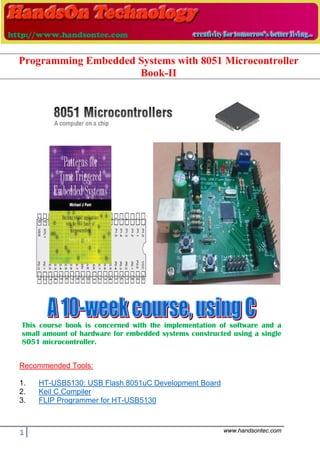
  • 1. 1 www.handsontec.com This course book is concerned with the implementation of software and a small amount of hardware for embedded systems constructed using a single 8051 microcontroller. Recommended Tools: 1. HT-USB5130: USB Flash 8051uC Development Board 2. Keil C Compiler 3. FLIP Programmer for HT-USB5130 Programming Embedded Systems with 8051 Microcontroller Book-II
  • 2. III Seminar 1: 1 Seminar 2: A flexible scheduler for single-processor embedded systems 1 Overview of this seminar 2 Overview of this course 3 By the end of the course you’ll be able to … 4 Main course text 5 IMPORTANT: Course prerequisites 6 Review: Why use C? 7 Review: The 8051 microcontroller 8 Review: The “super loop” software architecture 9 Review: An introduction to schedulers 10 Review: Building a scheduler 11 Overview of this seminar 12 The Co-operative Scheduler 13 Overview 14 The scheduler data structure and task array 15 The size of the task array 16 One possible initialisation function: 17 IMPORTANT: The ‘one interrupt per microcontroller’ rule! 18 The ‘Update’ function 19 The ‘Add Task’ function 20 The ‘Dispatcher’ 22 Function arguments 24 Function pointers and Keil linker options 25 The ‘Start’ function 28 The ‘Delete Task’ function 29 Reducing power consumption 30 Reporting errors 31 Displaying error codes 34 Hardware resource implications 35 What is the CPU load of the scheduler? 36 Determining the required tick interval 38 Guidelines for predictable and reliable scheduling 40 Overall strengths and weaknesses of the scheduler 41 Preparations for the next seminar 42
  • 3. IV Seminar 3: Analogue I/O using ADCs and PWM 43 Overview of this seminar 44 PATTERN: One-Shot ADC 45 PATTERN: One-Shot ADC 46 Using a microcontroller with on-chip ADC 47 Using an external parallel ADC 48 Example: Using a Max150 ADC 49 Using an external serial ADC 51 Example: Using an external SPI ADC 52 Overview of SPI 53 Back to the example … 54 Example: Using an external I2 C ADC 55 Overview of I2C 56 Back to the example … 57 What is PWM? 58 PATTERN: Software PWM 59 Preparations for the next seminar 62
  • 4. V Seminar 4: A closer look at co-operative task scheduling (and some alternatives) 63 Overview of this seminar 64 Review: Co-operative scheduling 65 The pre-emptive scheduler 66 Why do we avoid pre-emptive schedulers in this course? 67 Why is a co-operative scheduler (generally) more reliable? 68 Critical sections of code 69 How do we deal with critical sections in a pre-emptive system? 70 Building a “lock” mechanism 71 The “best of both worlds” - a hybrid scheduler 75 Creating a hybrid scheduler 76 The ‘Update’ function for a hybrid scheduler. 78 Reliability and safety issues 81 The safest way to use the hybrid scheduler 83 Other forms of co-operative scheduler 85 PATTERN: 255-TICK SCHEDULER 86 PATTERN: ONE-TASK SCHEDULER 87 PATTERN: ONE-YEAR SCHEDULER 88 PATTERN: STABLE SCHEDULER 89 Mix and match … 90 Preparations for the next seminar 91
  • 5. VI Seminar 5: Improving system reliability using watchdog timers 93 Overview of this seminar 94 The watchdog analogy 95 PATTERN: Watchdog Recovery 96 Choice of hardware 97 Time-based error detection 98 Other uses for watchdog-induced resets 99 Recovery behaviour 100 Risk assessment 101 The limitations of single-processor designs 102 Time, time, time … 103 Watchdogs: Overall strengths and weaknesses 104 PATTERN: Scheduler Watchdog 105 Selecting the overflow period - “hard” constraints 106 Selecting the overflow period - “soft” constraints 107 PATTERN: Program-Flow Watchdog 108 Dealing with errors 110 Hardware resource implications 111 Speeding up the response 112 PATTERN: Reset Recovery 114 PATTERN: Fail-Silent Recovery 115 Example: Fail-Silent behaviour in the Airbus A310 116 Example: Fail-Silent behaviour in a steer-by-wire application 117 PATTERN: Limp-Home Recovery 118 Example: Limp-home behaviour in a steer-by-wire application 119 PATTERN: Oscillator Watchdog 122 Preparations for the next seminar 124
  • 6. VII Seminar 6: Shared-clock schedulers for multi-processor systems 125 Overview of this seminar 126 Why use more than one processor? 127 Additional CPU performance and hardware facilities 128 The benefits of modular design 130 The benefits of modular design 131 So - how do we link more than one processor? 132 Synchronising the clocks 133 Synchronising the clocks 134 Synchronising the clocks - Slave nodes 135 Transferring data 136 Transferring data (Master to Slave) 137 Transferring data (Slave to Master) 138 Transferring data (Slave to Master) 139 Detecting network and node errors 140 Detecting errors in the Slave(s) 141 Detecting errors in the Master 142 Handling errors detected by the Slave 143 Handling errors detected by the Master 144 Enter a safe state and shut down the network 145 Reset the network 146 Engage a backup Slave 147 Why additional processors may not improve reliability 148 Redundant networks do not guarantee increased reliability 149 Replacing the human operator - implications 150 Are multi-processor designs ever safe? 151 Preparations for the next seminar 152
  • 7. VIII Seminar 7: Linking processors using RS-232 and RS-485 protocols 153 Review: Shared-clock scheduling 154 Overview of this seminar 155 Review: What is ‘RS-232’? 156 Review: Basic RS-232 Protocol 157 Review: Transferring data to a PC using RS-232 158 PATTERN: SCU SCHEDULER (LOCAL) 159 The message structure 160 Determining the required baud rate 163 Node Hardware 165 Network wiring 166 Overall strengths and weaknesses 167 PATTERN: SCU Scheduler (RS-232) 168 PATTERN: SCU Scheduler (RS-485) 169 RS-232 vs RS-485 [number of nodes] 170 RS-232 vs RS-485 [range and baud rates] 171 RS-232 vs RS-485 [cabling] 172 RS-232 vs RS-485 [transceivers] 173 Software considerations: enable inputs 174 Overall strengths and weaknesses 175 Example: Network with Max489 transceivers 176 Preparations for the next seminar 177
  • 8. IX Seminar 8: Linking processors using the Controller Area Network (CAN) bus 179 Overview of this seminar 180 PATTERN: SCC Scheduler 181 What is CAN? 182 CAN 1.0 vs. CAN 2.0 184 Basic CAN vs. Full CAN 185 Which microcontrollers have support for CAN? 186 S-C scheduling over CAN 187 The message structure - Tick messages 188 The message structure - Ack messages 189 Determining the required baud rate 190 Transceivers for distributed networks 192 Node wiring for distributed networks 193 Hardware and wiring for local networks 194 Software for the shared-clock CAN scheduler 195 Overall strengths and weaknesses 196 Example: Creating a CAN-based scheduler using the Infineon C515c 197 Master Software 198 Slave Software 211 What about CAN without on-chip hardware support? 218 Preparations for the next seminar 220
  • 9. X Seminar 9: Applying “Proportional Integral Differential” (PID) control 221 Overview of this seminar 222 Why do we need closed-loop control? 223 Closed-loop control 227 What closed-loop algorithm should you use? 228 What is PID control? 229 A complete PID control implementation 230 Another version 231 Dealing with ‘windup’ 232 Choosing the controller parameters 233 What sample rate? 234 Hardware resource implications 235 PID: Overall strengths and weaknesses 236 Why open-loop controllers are still (sometimes) useful 237 Limitations of PID control 238 Example: Tuning the parameters of a cruise-control system 239 Open-loop test 241 Tuning the PID parameters: methodology 242 First test 243 Example: DC Motor Speed Control 245 Alternative: Fuzzy control 248 Preparations for the next seminar 249
  • 10. XI Seminar 10: Case study: Automotive cruise control using PID and CAN 251 Overview of this seminar 252 Single-processor system: Overview 253 Single-processor system: Code 254 Multi-processor design: Overview 255 Multi-processor design: Code (PID node) 256 Multi-processor design: Code (Speed node) 257 Multi-processor design: Code (Throttle node) 258 Exploring the impact of network delays 259 Example: Impact of network delays on the CCS system 260 That’s it! 261
  • 11. XII
  • 12. COPYRIGHT © MICHAEL J. PONT, 2001-2004. Contains material from: Pont, M.J. (2001) “Patterns for triggered embedded systems”, Addison-Wesley. PES II - 1 Seminar 1: Seminar 2: A flexible scheduler for single-processor embedded systems 40 39 38 37 36 35 34 1 2 3 4 5 6 7 ‘8051’ 8 9 10 33 32 31 30 29 28 27 26 25 24 11 12 13 14 15 16 17 18 19 20 23 22 21 P3.0 P1.7 RST P1.6 P1.5 P1.4 P1.2 P1.3 P1.1 P1.0 VSS XTL2 XTL1 P3.7 P3.6 P3.5 P3.3 P3.4 P3.2 P3.1 /EA P0.6 P0.7 P0.5 P0.4 P0.3 P0.1 P0.2 P0.0 VCC P2.0 P2.2 P2.1 P2.3 P2.4 P2.5 P2.7 P2.6 /PSEN ALE
  • 13. COPYRIGHT © MICHAEL J. PONT, 2001-2004. Contains material from: Pont, M.J. (2001) “Patterns for triggered embedded systems”, Addison-Wesley. PES II - 2 Overview of this seminar This introductory seminar will run over TWO SESSIONS: It will: x Provide an overview of this course (this seminar slot) x Describe the design and implementation of a flexible scheduler (this slot and the next slot)
  • 14. COPYRIGHT © MICHAEL J. PONT, 2001-2004. Contains material from: Pont, M.J. (2001) “Patterns for triggered embedded systems”, Addison-Wesley. PES II - 3 Overview of this course This course is primarily concerned with the implementation of software (and a small amount of hardware) for embedded systems constructed using more than one microcontroller. The processors examined in detail will be from the 8051 family. All programming will be in the ‘C’ language (using the Keil C51 compiler)
  • 15. COPYRIGHT © MICHAEL J. PONT, 2001-2004. Contains material from: Pont, M.J. (2001) “Patterns for triggered embedded systems”, Addison-Wesley. PES II - 4 By the end of the course you’ll be able to … By the end of the course, you will be able to: 1. Design software for multi-processor embedded applications based on small, industry standard, microcontrollers; 2. Implement the above designs using a modern, high-level programming language (‘C’), and 3. Understand more about the effect that software design and programming designs can have on the reliability and safety of multi-processor embedded systems.
  • 16. COPYRIGHT © MICHAEL J. PONT, 2001-2004. Contains material from: Pont, M.J. (2001) “Patterns for triggered embedded systems”, Addison-Wesley. PES II - 5 Main course text Throughout this course, we will be making heavy use of this book: Patterns for time-triggered embedded systems: Building reliable applications with the 8051 family of microcontrollers, by Michael J. Pont (2001) Addison-Wesley / ACM Press. [ISBN: 0-201-331381] For further details, please see: http://www.engg.le.ac.uk/books/Pont/pttes.htm
  • 17. COPYRIGHT © MICHAEL J. PONT, 2001-2004. Contains material from: Pont, M.J. (2001) “Patterns for triggered embedded systems”, Addison-Wesley. PES II - 6 IMPORTANT: Course prerequisites x It is assumed that - before taking this course - you have previously completed “Programming Embedded Systems I” (or a similar course). See: www.le.ac.uk/engineering/mjp9/pttesguide.htm B E C 5.5V, 0.3A lamp ZTX751 4V - 6V (battery) 10 K: 10 μF 4 MHz 20 19 18 17 16 15 14 1 2 3 4 5 6 7 Atmel2051 8 9 10 13 12 11GND P3.4 P3.5 P3.3 P3.2 XTL1 P3.1 XTL2 P3.0 RST P3.7 P1.1 P1.0 P1.2 P1.3 P1.4 P1.6 P1.5 P1.7 VCC 40 39 38 37 36 35 34 1 2 3 4 5 6 7 ‘8051’ 8 9 10 33 32 31 30 29 28 27 26 25 24 11 12 13 14 15 16 17 18 19 20 23 22 21 P3.0 P1.7 RST P1.6 P1.5 P1.4 P1.2 P1.3 P1.1 P1.0 VSS XTL2 XTL1 P3.7 P3.6 P3.5 P3.3 P3.4 P3.2 P3.1 /EA P0.6 P0.7 P0.5 P0.4 P0.3 P0.1 P0.2 P0.0 VCC P2.0 P2.2 P2.1 P2.3 P2.4 P2.5 P2.7 P2.6 /PSEN ALE
  • 18. COPYRIGHT © MICHAEL J. PONT, 2001-2004. Contains material from: Pont, M.J. (2001) “Patterns for triggered embedded systems”, Addison-Wesley. PES II - 7 Review: Why use C? x It is a ‘mid-level’ language, with ‘high-level’ features (such as support for functions and modules), and ‘low-level’ features (such as good access to hardware via pointers); x It is very efficient; x It is popular and well understood; x Even desktop developers who have used only Java or C++ can soon understand C syntax; x Good, well-proven compilers are available for every embedded processor (8-bit to 32-bit or more); x Experienced staff are available; x Books, training courses, code samples and WWW sites discussing the use of the language are all widely available. Overall, C may not be an ideal language for developing embedded systems, but it is a good choice (and is unlikely that a ‘perfect’ language will ever be created).
  • 19. COPYRIGHT © MICHAEL J. PONT, 2001-2004. Contains material from: Pont, M.J. (2001) “Patterns for triggered embedded systems”, Addison-Wesley. PES II - 8 Review: The 8051 microcontroller 40 39 38 37 36 35 34 1 2 3 4 5 6 7 ‘8051’ 8 9 10 33 32 31 30 29 28 27 26 25 24 11 12 13 14 15 16 17 18 19 20 23 22 21 P3.0 P1.7 RST P1.6 P1.5 P1.4 P1.2 P1.3 P1.1 P1.0 VSS XTL2 XTL1 P3.7 P3.6 P3.5 P3.3 P3.4 P3.2 P3.1 /EA P0.6 P0.7 P0.5 P0.4 P0.3 P0.1 P0.2 P0.0 VCC P2.0 P2.2 P2.1 P2.3 P2.4 P2.5 P2.7 P2.6 /PSEN ALE Typical features of a modern 8051: x Thirty-two input / output lines. x Internal data (RAM) memory - 256 bytes. x Up to 64 kbytes of ROM memory (usually flash) x Three 16-bit timers / counters x Nine interrupts (two external) with two priority levels. x Low-power Idle and Power-down modes. The different members of the 8051 family are suitable for a huge range of projects - from automotive and aerospace systems to TV “remotes”.
  • 20. COPYRIGHT © MICHAEL J. PONT, 2001-2004. Contains material from: Pont, M.J. (2001) “Patterns for triggered embedded systems”, Addison-Wesley. PES II - 9 Review: The “super loop” software architecture Problem What is the minimum software environment you need to create an embedded C program? Solution void main(void) { /* Prepare for Task X */ X_Init(); while(1) /* 'for ever' (Super Loop) */ { X(); /* Perform the task */ } } Crucially, the ‘super loop’, or ‘endless loop’, is required because we have no operating system to return to: our application will keep looping until the system power is removed.
  • 21. COPYRIGHT © MICHAEL J. PONT, 2001-2004. Contains material from: Pont, M.J. (2001) “Patterns for triggered embedded systems”, Addison-Wesley. PES II - 10 Review: An introduction to schedulers Operating System BIOS Hardware Word Processor OS provides ‘common code’ for: • Graphics • Printing • File storage • Sound • ... Many embedded systems must carry out tasks at particular instants of time. More specifically, we have two kinds of activity to perform: x Periodic tasks, to be performed (say) once every 100 ms, and - less commonly - x One-shot tasks, to be performed once after a delay of (say) 50 ms.
  • 22. COPYRIGHT © MICHAEL J. PONT, 2001-2004. Contains material from: Pont, M.J. (2001) “Patterns for triggered embedded systems”, Addison-Wesley. PES II - 11 Review: Building a scheduler void main(void) { Timer_2_Init(); /* Set up Timer 2 */ EA = 1; /* Globally enable interrupts */ while(1); /* An empty Super Loop */ } void Timer_2_Init(void) { /* Timer 2 is configured as a 16-bit timer, which is automatically reloaded when it overflows With these setting, timer will overflow every 1 ms */ T2CON = 0x04; /* Load T2 control register */ T2MOD = 0x00; /* Load T2 mode register */ TH2 = 0xFC; /* Load T2 high byte */ RCAP2H = 0xFC; /* Load T2 reload capt. reg. high byte */ TL2 = 0x18; /* Load T2 low byte */ RCAP2L = 0x18; /* Load T2 reload capt. reg. low byte */ /* Timer 2 interrupt is enabled, and ISR will be called whenever the timer overflows - see below. */ ET2 = 1; /* Start Timer 2 running */ TR2 = 1; } void X(void) interrupt INTERRUPT_Timer_2_Overflow { /* This ISR is called every 1 ms */ /* Place required code here... */ }
  • 23. COPYRIGHT © MICHAEL J. PONT, 2001-2004. Contains material from: Pont, M.J. (2001) “Patterns for triggered embedded systems”, Addison-Wesley. PES II - 12 Overview of this seminar This seminar will consider the design of a very flexible scheduler. THE CO-OPERATIVE SCHEDULER x A co-operative scheduler provides a single-tasking system architecture Operation: x Tasks are scheduled to run at specific times (either on a one-shot or regular basis) x When a task is scheduled to run it is added to the waiting list x When the CPU is free, the next waiting task (if any) is executed x The task runs to completion, then returns control to the scheduler Implementation: x The scheduler is simple, and can be implemented in a small amount of code. x The scheduler must allocate memory for only a single task at a time. x The scheduler will generally be written entirely in a high-level language (such as ‘C’). x The scheduler is not a separate application; it becomes part of the developer’s code Performance: x Obtain rapid responses to external events requires care at the design stage. Reliability and safety: x Co-operate scheduling is simple, predictable, reliable and safe.
  • 24. COPYRIGHT © MICHAEL J. PONT, 2001-2004. Contains material from: Pont, M.J. (2001) “Patterns for triggered embedded systems”, Addison-Wesley. PES II - 13 The Co-operative Scheduler A scheduler has the following key components: x The scheduler data structure. x An initialisation function. x A single interrupt service routine (ISR), used to update the scheduler at regular time intervals. x A function for adding tasks to the scheduler. x A dispatcher function that causes tasks to be executed when they are due to run. x A function for removing tasks from the scheduler (not required in all applications). We will consider each of the required components in turn.
  • 25. COPYRIGHT © MICHAEL J. PONT, 2001-2004. Contains material from: Pont, M.J. (2001) “Patterns for triggered embedded systems”, Addison-Wesley. PES II - 14 Overview /*--------------------------------------------------------*/ void main(void) { /* Set up the scheduler */ SCH_Init_T2(); /* Prepare for the 'Flash_LED' task */ LED_Flash_Init(); /* Add the 'Flash LED' task (on for ~1000 ms, off for ~1000 ms) Timings are in ticks (1 ms tick interval) (Max interval / delay is 65535 ticks) */ SCH_Add_Task(LED_Flash_Update, 0, 1000); /* Start the scheduler */ SCH_Start(); while(1) { SCH_Dispatch_Tasks(); } } /*--------------------------------------------------------*/ void SCH_Update(void) interrupt INTERRUPT_Timer_2_Overflow { /* Update the task list */ ... }
  • 26. COPYRIGHT © MICHAEL J. PONT, 2001-2004. Contains material from: Pont, M.J. (2001) “Patterns for triggered embedded systems”, Addison-Wesley. PES II - 15 The scheduler data structure and task array /* Store in DATA area, if possible, for rapid access Total memory per task is 7 bytes */ typedef data struct { /* Pointer to the task (must be a 'void (void)' function) */ void (code * pTask)(void); /* Delay (ticks) until the function will (next) be run - see SCH_Add_Task() for further details */ tWord Delay; /* Interval (ticks) between subsequent runs. - see SCH_Add_Task() for further details */ tWord Repeat; /* Incremented (by scheduler) when task is due to execute */ tByte RunMe; } sTask; File Sch51.H also includes the constant SCH_MAX_TASKS: /* The maximum number of tasks required at any one time during the execution of the program MUST BE ADJUSTED FOR EACH NEW PROJECT */ #define SCH_MAX_TASKS (1) Both the sTask data type and the SCH_MAX_TASKS constant are used to create - in the file Sch51.C - the array of tasks that is referred to throughout the scheduler: /* The array of tasks */ sTask SCH_tasks_G[SCH_MAX_TASKS];
  • 27. COPYRIGHT © MICHAEL J. PONT, 2001-2004. Contains material from: Pont, M.J. (2001) “Patterns for triggered embedded systems”, Addison-Wesley. PES II - 16 The size of the task array You must ensure that the task array is sufficiently large to store the tasks required in your application, by adjusting the value of SCH_MAX_TASKS. For example, if you schedule three tasks as follows: SCH_Add_Task(Function_A, 0, 2); SCH_Add_Task(Function_B, 1, 10); SCH_Add_Task(Function_C, 3, 15); …then SCH_MAX_TASKS must have a value of 3 (or more) for correct operation of the scheduler. Note also that - if this condition is not satisfied, the scheduler will generate an error code (more on this later).
  • 28. COPYRIGHT © MICHAEL J. PONT, 2001-2004. Contains material from: Pont, M.J. (2001) “Patterns for triggered embedded systems”, Addison-Wesley. PES II - 17 One possible initialisation function: /*--------------------------------------------------------*/ void SCH_Init_T2(void) { tByte i; for (i = 0; i < SCH_MAX_TASKS; i++) { SCH_Delete_Task(i); } /* SCH_Delete_Task() will generate an error code, because the task array is empty. -> reset the global error variable. */ Error_code_G = 0; /* Now set up Timer 2 16-bit timer function with automatic reload Crystal is assumed to be 12 MHz The Timer 2 resolution is 0.000001 seconds (1 μs) The required Timer 2 overflow is 0.001 seconds (1 ms) - this takes 1000 timer ticks Reload value is 65536 - 1000 = 64536 (dec) = 0xFC18 */ T2CON = 0x04; /* Load Timer 2 control register */ T2MOD = 0x00; /* Load Timer 2 mode register */ TH2 = 0xFC; /* Load Timer 2 high byte */ RCAP2H = 0xFC; /* Load Timer 2 reload capture reg, high byte */ TL2 = 0x18; /* Load Timer 2 low byte */ RCAP2L = 0x18; /* Load Timer 2 reload capture reg, low byte */ ET2 = 1; /* Timer 2 interrupt is enabled */ TR2 = 1; /* Start Timer 2 */ }
  • 29. COPYRIGHT © MICHAEL J. PONT, 2001-2004. Contains material from: Pont, M.J. (2001) “Patterns for triggered embedded systems”, Addison-Wesley. PES II - 18 IMPORTANT: The ‘one interrupt per microcontroller’ rule! The scheduler initialisation function enables the generation of interrupts associated with the overflow of one of the microcontroller timers. For reasons discussed in Chapter 1 of PTTES, it is assumed throughout this course that only the ‘tick’ interrupt source is active: specifically, it is assumed that no other interrupts are enabled. If you attempt to use the scheduler code with additional interrupts enabled, the system cannot be guaranteed to operate at all: at best, you will generally obtain very unpredictable - and unreliable - system behaviour.
  • 30. COPYRIGHT © MICHAEL J. PONT, 2001-2004. Contains material from: Pont, M.J. (2001) “Patterns for triggered embedded systems”, Addison-Wesley. PES II - 19 The ‘Update’ function /*--------------------------------------------------------*/ void SCH_Update(void) interrupt INTERRUPT_Timer_2_Overflow { tByte Index; TF2 = 0; /* Have to manually clear this. */ /* NOTE: calculations are in *TICKS* (not milliseconds) */ for (Index = 0; Index < SCH_MAX_TASKS; Index++) { /* Check if there is a task at this location */ if (SCH_tasks_G[Index].pTask) { if (--SCH_tasks_G[Index].Delay == 0) { /* The task is due to run */ SCH_tasks_G[Index].RunMe += 1; /* Inc. 'RunMe' flag */ if (SCH_tasks_G[Index].Period) { /* Schedule regular tasks to run again */ SCH_tasks_G[Index].Delay = SCH_tasks_G[Index].Period; } } } } }
  • 31. COPYRIGHT © MICHAEL J. PONT, 2001-2004. Contains material from: Pont, M.J. (2001) “Patterns for triggered embedded systems”, Addison-Wesley. PES II - 20 The ‘Add Task’ function Sch_Add_Task(Task_Name, Initial_Delay, Task_Interval); Task_Name the name of the function (task) that you wish to schedule Task_Interval the interval (in ticks) between repeated executions of the task. If set to 0, the task is executed only once. Initial_Delay the delay (in ticks) before task is first executed. If set to 0, the task is executed immediately. Examples: SCH_Add_Task(Do_X,1000,0); Task_ID = SCH_Add_Task(Do_X,1000,0); SCH_Add_Task(Do_X,0,1000); This causes the function Do_X() to be executed regularly, every 1000 scheduler ticks; task will be first executed at T = 300 ticks, then 1300, 2300, etc: SCH_Add_Task(Do_X,300,1000);
  • 32. COPYRIGHT © MICHAEL J. PONT, 2001-2004. Contains material from: Pont, M.J. (2001) “Patterns for triggered embedded systems”, Addison-Wesley. PES II - 21 /*--------------------------------------------------------*- SCH_Add_Task() Causes a task (function) to be executed at regular intervals, or after a user-defined delay. -*--------------------------------------------------------*/ tByte SCH_Add_Task(void (code * pFunction)(), const tWord DELAY, const tWord PERIOD) { tByte Index = 0; /* First find a gap in the array (if there is one) */ while ((SCH_tasks_G[Index].pTask != 0) && (Index < SCH_MAX_TASKS)) { Index++; } /* Have we reached the end of the list? */ if (Index == SCH_MAX_TASKS) { /* Task list is full -> set the global error variable */ Error_code_G = ERROR_SCH_TOO_MANY_TASKS; /* Also return an error code */ return SCH_MAX_TASKS; } /* If we're here, there is a space in the task array */ SCH_tasks_G[Index].pTask = pFunction; SCH_tasks_G[Index].Delay = DELAY + 1; SCH_tasks_G[Index].Period = PERIOD; SCH_tasks_G[Index].RunMe = 0; return Index; /* return pos. of task (to allow deletion) */ }
  • 33. COPYRIGHT © MICHAEL J. PONT, 2001-2004. Contains material from: Pont, M.J. (2001) “Patterns for triggered embedded systems”, Addison-Wesley. PES II - 22 The ‘Dispatcher’ /*--------------------------------------------------------*- SCH_Dispatch_Tasks() This is the 'dispatcher' function. When a task (function) is due to run, SCH_Dispatch_Tasks() will run it. This function must be called (repeatedly) from the main loop. -*--------------------------------------------------------*/ void SCH_Dispatch_Tasks(void) { tByte Index; /* Dispatches (runs) the next task (if one is ready) */ for (Index = 0; Index < SCH_MAX_TASKS; Index++) { if (SCH_tasks_G[Index].RunMe > 0) { (*SCH_tasks_G[Index].pTask)(); /* Run the task */ SCH_tasks_G[Index].RunMe -= 1; /* Reduce RunMe count */ /* Periodic tasks will automatically run again - if this is a 'one shot' task, delete it */ if (SCH_tasks_G[Index].Period == 0) { SCH_Delete_Task(Index); } } } /* Report system status */ SCH_Report_Status(); /* The scheduler enters idle mode at this point */ SCH_Go_To_Sleep(); }
  • 34. COPYRIGHT © MICHAEL J. PONT, 2001-2004. Contains material from: Pont, M.J. (2001) “Patterns for triggered embedded systems”, Addison-Wesley. PES II - 23 The dispatcher is the only component in the Super Loop: /* ----------------------------------------------------- */ void main(void) { ... while(1) { SCH_Dispatch_Tasks(); }
  • 35. COPYRIGHT © MICHAEL J. PONT, 2001-2004. Contains material from: Pont, M.J. (2001) “Patterns for triggered embedded systems”, Addison-Wesley. PES II - 24 Function arguments x On desktop systems, function arguments are generally passed on the stack using the push and pop assembly instructions. x Since the 8051 has a size limited stack (only 128 bytes at best and as low as 64 bytes on some devices), function arguments must be passed using a different technique. x In the case of Keil C51, these arguments are stored in fixed memory locations. x When the linker is invoked, it builds a call tree of the program, decides which function arguments are mutually exclusive (that is, which functions cannot be called at the same time), and overlays these arguments.
  • 36. COPYRIGHT © MICHAEL J. PONT, 2001-2004. Contains material from: Pont, M.J. (2001) “Patterns for triggered embedded systems”, Addison-Wesley. PES II - 25 Function pointers and Keil linker options When we write: SCH_Add_Task(Do_X,1000,0); …the first parameter of the ‘Add Task’ function is a pointer to the function Do_X(). This function pointer is then passed to the Dispatch function and it is through this function that the task is executed: if (SCH_tasks_G[Index].RunMe > 0) { (*SCH_tasks_G[Index].pTask)(); /* Run the task */ BUT The linker has difficulty determining the correct call tree when function pointers are used as arguments.
  • 37. COPYRIGHT © MICHAEL J. PONT, 2001-2004. Contains material from: Pont, M.J. (2001) “Patterns for triggered embedded systems”, Addison-Wesley. PES II - 26 To deal with this situation, you have two realistic options: 1. You can prevent the compiler from using the OVERLAY directive by disabling overlays as part of the linker options for your project. Note that, compared to applications using overlays, you will generally require more RAM to run your program. 2. You can tell the linker how to create the correct call tree for your application by explicitly providing this information in the linker ‘Additional Options’ dialogue box. This approach is used in most of the examples in the “PTTES” book.
  • 38. COPYRIGHT © MICHAEL J. PONT, 2001-2004. Contains material from: Pont, M.J. (2001) “Patterns for triggered embedded systems”, Addison-Wesley. PES II - 27 void main(void) { ... /* Read the ADC regularly */ SCH_Add_Task(AD_Get_Sample, 10, 1000); /* Simply display the count here (bargraph display) */ SCH_Add_Task(BARGRAPH_Update, 12, 1000); /* All tasks added: start running the scheduler */ SCH_Start(); The corresponding OVERLAY directive would take this form: OVERLAY (main ~ (AD_Get_Sample,Bargraph_Update), sch_dispatch_tasks ! (AD_Get_Sample,Bargraph_Update))
  • 39. COPYRIGHT © MICHAEL J. PONT, 2001-2004. Contains material from: Pont, M.J. (2001) “Patterns for triggered embedded systems”, Addison-Wesley. PES II - 28 The ‘Start’ function /*--------------------------------------------------------*/ void SCH_Start(void) { EA = 1; }
  • 40. COPYRIGHT © MICHAEL J. PONT, 2001-2004. Contains material from: Pont, M.J. (2001) “Patterns for triggered embedded systems”, Addison-Wesley. PES II - 29 The ‘Delete Task’ function When tasks are added to the task array, SCH_Add_Task() returns the position in the task array at which the task has been added: Task_ID = SCH_Add_Task(Do_X,1000,0); Sometimes it can be necessary to delete tasks from the array. You can do so as follows: SCH_Delete_Task(Task_ID); bit SCH_Delete_Task(const tByte TASK_INDEX) { bit Return_code; if (SCH_tasks_G[TASK_INDEX].pTask == 0) { /* No task at this location... -> set the global error variable */ Error_code_G = ERROR_SCH_CANNOT_DELETE_TASK; /* ...also return an error code */ Return_code = RETURN_ERROR; } else { Return_code = RETURN_NORMAL; } SCH_tasks_G[TASK_INDEX].pTask = 0x0000; SCH_tasks_G[TASK_INDEX].Delay = 0; SCH_tasks_G[TASK_INDEX].Period = 0; SCH_tasks_G[TASK_INDEX].RunMe = 0; return Return_code; /* return status */ }
  • 41. COPYRIGHT © MICHAEL J. PONT, 2001-2004. Contains material from: Pont, M.J. (2001) “Patterns for triggered embedded systems”, Addison-Wesley. PES II - 30 Reducing power consumption /*--------------------------------------------------------*/ void SCH_Go_To_Sleep() { PCON |= 0x01; /* Enter idle mode (generic 8051 version) */ /* Entering idle mode requires TWO consecutive instructions on 80c515 / 80c505 - to avoid accidental triggering. E.g: PCON |= 0x01; PCON |= 0x20; */ }
  • 42. COPYRIGHT © MICHAEL J. PONT, 2001-2004. Contains material from: Pont, M.J. (2001) “Patterns for triggered embedded systems”, Addison-Wesley. PES II - 31 Reporting errors /* Used to display the error code */ tByte Error_code_G = 0; To record an error we include lines such as: Error_code_G = ERROR_SCH_TOO_MANY_TASKS; Error_code_G = ERROR_SCH_WAITING_FOR_SLAVE_TO_ACK; Error_code_G = ERROR_SCH_WAITING_FOR_START_COMMAND_FROM_MASTER; Error_code_G = ERROR_SCH_ONE_OR_MORE_SLAVES_DID_NOT_START; Error_code_G = ERROR_SCH_LOST_SLAVE; Error_code_G = ERROR_SCH_CAN_BUS_ERROR; Error_code_G = ERROR_I2C_WRITE_BYTE_AT24C64; To report these error code, the scheduler has a function SCH_Report_Status(), which is called from the Update function.
  • 43. COPYRIGHT © MICHAEL J. PONT, 2001-2004. Contains material from: Pont, M.J. (2001) “Patterns for triggered embedded systems”, Addison-Wesley. PES II - 32 /*--------------------------------------------------------*/ void SCH_Report_Status(void) { #ifdef SCH_REPORT_ERRORS /* ONLY APPLIES IF WE ARE REPORTING ERRORS */ /* Check for a new error code */ if (Error_code_G != Last_error_code_G) { /* Negative logic on LEDs assumed */ Error_port = 255 - Error_code_G; Last_error_code_G = Error_code_G; if (Error_code_G != 0) { Error_tick_count_G = 60000; } else { Error_tick_count_G = 0; } } else { if (Error_tick_count_G != 0) { if (--Error_tick_count_G == 0) { Error_code_G = 0; /* Reset error code */ } } } #endif }
  • 44. COPYRIGHT © MICHAEL J. PONT, 2001-2004. Contains material from: Pont, M.J. (2001) “Patterns for triggered embedded systems”, Addison-Wesley. PES II - 33 Note that error reporting may be disabled via the Port.H header file: /* Comment next line out if error reporting is NOT required */ /* #define SCH_REPORT_ERRORS */ Where error reporting is required, the port on which error codes will be displayed is also determined via Port.H: #ifdef SCH_REPORT_ERRORS /* The port on which error codes will be displayed (ONLY USED IF ERRORS ARE REPORTED) */ #define Error_port P1 #endif Note that, in this implementation, error codes are reported for 60,000 ticks (1 minute at a 1 ms tick rate).
  • 45. COPYRIGHT © MICHAEL J. PONT, 2001-2004. Contains material from: Pont, M.J. (2001) “Patterns for triggered embedded systems”, Addison-Wesley. PES II - 34 Displaying error codes Rled Rled Rled Rled Rled Rled Rled Rled LED 7 LED 6 LED 5 LED 4 LED 3 LED 2 LED 1 LED 0 8051 Device Port 2 Vcc ULN2803A 9 P2.0 - Pin 8 P2.1 - Pin 7 P2.2 - Pin 6 P2.3 - Pin 5 P2.4 - Pin 4 P2.5 - Pin 3 P2.6 - Pin 2 P2.7 - Pin 1 Pin 11 - LED 0 Pin 12 - LED 1 Pin 13 - LED 2 Pin 14 - LED 3 Pin 15 - LED 4 Pin 16 - LED 5 Pin 17 - LED 6 Pin 18 - LED 7 For 25mA LEDs, Rled = 120 Ohms The forms of error reporting discussed here are low-level in nature and are primarily intended to assist the developer of the application, or a qualified service engineer performing system maintenance. An additional user interface may also be required in your application to notify the user of errors, in a more user-friendly manner.
  • 46. COPYRIGHT © MICHAEL J. PONT, 2001-2004. Contains material from: Pont, M.J. (2001) “Patterns for triggered embedded systems”, Addison-Wesley. PES II - 35 Hardware resource implications Timer The scheduler requires one hardware timer. If possible, this should be a 16-bit timer, with auto-reload capabilities (usually Timer 2). Memory This main scheduler memory requirement is 7 bytes of memory per task. Most applications require around six tasks or less. Even in a standard 8051/8052 with 256 bytes of internal memory the total memory overhead is small.
  • 47. COPYRIGHT © MICHAEL J. PONT, 2001-2004. Contains material from: Pont, M.J. (2001) “Patterns for triggered embedded systems”, Addison-Wesley. PES II - 36 What is the CPU load of the scheduler? x A scheduler with 1ms ticks x 12 Mhz, 12 osc / instruction 8051 x One task is being executed. x The test reveals that the CPU is 86% idle and that the maximum possible task duration is therefore approximately 0.86 ms.
  • 48. COPYRIGHT © MICHAEL J. PONT, 2001-2004. Contains material from: Pont, M.J. (2001) “Patterns for triggered embedded systems”, Addison-Wesley. PES II - 37 A scheduler with 1ms ticks, running on a 32 Mhz (4 oscillations per instruction) 8051. x One task is being executed. x The CPU is 97% idle and that the maximum possible task duration is therefore approximately 0.97 ms. x Twelve tasks are being executed. x The CPU is 85% idle and that the maximum possible task duration is therefore approximately 0.85 ms.
  • 49. COPYRIGHT © MICHAEL J. PONT, 2001-2004. Contains material from: Pont, M.J. (2001) “Patterns for triggered embedded systems”, Addison-Wesley. PES II - 38 Determining the required tick interval In most instances, the simplest way of meeting the needs of the various task intervals is to allocate a scheduler tick interval of 1 ms. To keep the scheduler load as low as possible (and to reduce the power consumption), it can help to use a long tick interval. If you want to reduce overheads and power consumption to a minimum, the scheduler tick interval should be set to match the ‘greatest common factor’ of all the task (and offset intervals).
  • 50. COPYRIGHT © MICHAEL J. PONT, 2001-2004. Contains material from: Pont, M.J. (2001) “Patterns for triggered embedded systems”, Addison-Wesley. PES II - 39 Suppose we have three tasks (X,Y,Z), and Task X is to be run every 10 ms, Task Y every 30 ms and Task Z every 25 ms. The scheduler tick interval needs to be set by determining the relevant factors, as follows: x The factors of the Task X interval (10 ms) are: 1 ms, 2ms, 5 ms, 10 ms. x Similarly, the factors of the Task Y interval (30 ms) are as follows: 1 ms, 2 ms, 3 ms, 5 ms, 6 ms, 10 ms, 15 ms and 30 ms. x Finally, the factors of the Task Z interval (25 ms) are as follows: 1 ms, 5 ms and 25 ms. In this case, therefore, the greatest common factor is 5 ms: this is the required tick interval.
  • 51. COPYRIGHT © MICHAEL J. PONT, 2001-2004. Contains material from: Pont, M.J. (2001) “Patterns for triggered embedded systems”, Addison-Wesley. PES II - 40 Guidelines for predictable and reliable scheduling 1. For precise scheduling, the scheduler tick interval should be set to match the ‘greatest common factor’ of all the task intervals. 2. All tasks should have a duration less than the schedule tick interval, to ensure that the dispatcher is always free to call any task that is due to execute. Software simulation can often be used to measure the task duration. 3. In order to meet Condition 2, all tasks must ‘timeout’ so that they cannot block the scheduler under any circumstances. 4. The total time required to execute all of the scheduled tasks must be less than the available processor time. Of course, the total processor time must include both this ‘task time’ and the ‘scheduler time’ required to execute the scheduler update and dispatcher operations. 5. Tasks should be scheduled so that they are never required to execute simultaneously: that is, task overlaps should be minimised. Note that where all tasks are of a duration much less than the scheduler tick interval, and that some task jitter can be tolerated, this problem may not be significant.
  • 52. COPYRIGHT © MICHAEL J. PONT, 2001-2004. Contains material from: Pont, M.J. (2001) “Patterns for triggered embedded systems”, Addison-Wesley. PES II - 41 Overall strengths and weaknesses of the scheduler - The scheduler is simple, and can be implemented in a small amount of code. - The scheduler is written entirely in ‘C’: it is not a separate application, but becomes part of the developer’s code - The applications based on the scheduler are inherently predictable, safe and reliable. - The scheduler supports team working, since individual tasks can often be developed largely independently and then assembled into the final system. / Obtain rapid responses to external events requires care at the design stage. / The tasks cannot safely use interrupts: the only interrupt that should be used in the application is the timer-related interrupt that drives the scheduler itself.
  • 53. COPYRIGHT © MICHAEL J. PONT, 2001-2004. Contains material from: Pont, M.J. (2001) “Patterns for triggered embedded systems”, Addison-Wesley. PES II - 42 Preparations for the next seminar Please read “PTTES” Chapter 32 before the next seminar. 40 39 38 37 36 35 34 1 2 3 4 5 6 7 ‘8051’ 8 9 10 33 32 31 30 29 28 27 26 25 24 11 12 13 14 15 16 17 18 19 20 23 22 21 P3.0 P1.7 RST P1.6 P1.5 P1.4 P1.2 P1.3 P1.1 P1.0 VSS XTL2 XTL1 P3.7 P3.6 P3.5 P3.3 P3.4 P3.2 P3.1 /EA P0.6 P0.7 P0.5 P0.4 P0.3 P0.1 P0.2 P0.0 VCC P2.0 P2.2 P2.1 P2.3 P2.4 P2.5 P2.7 P2.6 /PSEN ALE
  • 54. COPYRIGHT © MICHAEL J. PONT, 2001-2004. Contains material from: Pont, M.J. (2001) “Patterns for triggered embedded systems”, Addison-Wesley. PES II - 43 Seminar 3: Analogue I/O using ADCs and PWM Transmitter (Master) Transmitter (Master) Receiver A (Slave) Receiver A (Slave) Receiver B (Slave) Receiver B (Slave) Receiver C (Slave) Receiver C (Slave)
  • 55. COPYRIGHT © MICHAEL J. PONT, 2001-2004. Contains material from: Pont, M.J. (2001) “Patterns for triggered embedded systems”, Addison-Wesley. PES II - 44 Overview of this seminar In this seminar, we will begin to consider how to make measurements of analogue voltages using a microcontroller. We’ll also consider how PWM can be used to generate analogue voltage values.
  • 56. COPYRIGHT © MICHAEL J. PONT, 2001-2004. Contains material from: Pont, M.J. (2001) “Patterns for triggered embedded systems”, Addison-Wesley. PES II - 45 PATTERN: One-Shot ADC1 In ONE-SHOT ADC, we are concerned with the use of analogue signals to address questions such as: x What central-heating temperature does the user require? x What is the current angle of the crane? x What is the humidity level in Greenhouse 3? 20oC 15oC 25oC 10oC 30oC 0.1 uF d +24v (DC) 0 50 k pot + 5v 0 - 5 v 0 To ADC 7805 1894 DownUp 3000 2000 4000 1000 5000 1 See PTTES p.757.
  • 57. COPYRIGHT © MICHAEL J. PONT, 2001-2004. Contains material from: Pont, M.J. (2001) “Patterns for triggered embedded systems”, Addison-Wesley. PES II - 46 PATTERN: One-Shot ADC We begin by considering some of the hardware options that are available to allow the measurement of analogue voltage signals using a microcontroller. Specifically, we will consider four options: x Using a microcontroller with on-chip ADC; x Using an external serial ADC; x Using an external parallel ADC; x Using a current-mode ADC.
  • 58. COPYRIGHT © MICHAEL J. PONT, 2001-2004. Contains material from: Pont, M.J. (2001) “Patterns for triggered embedded systems”, Addison-Wesley. PES II - 47 Using a microcontroller with on-chip ADC Many members of the 8051 family contain on-board ADCs. In general, use of an internal ADC (rather than an external one) will result in increased reliability, since both hardware and software complexity will generally be lower. In addition, the ‘internal’ solution will usually be physically smaller, and have a lower system cost.
  • 59. COPYRIGHT © MICHAEL J. PONT, 2001-2004. Contains material from: Pont, M.J. (2001) “Patterns for triggered embedded systems”, Addison-Wesley. PES II - 48 Using an external parallel ADC The ‘traditional’ alternative to an on-chip ADC is a parallel ADC. In general, parallel ADCs have the following strengths and weaknesses: - They can provide fast data transfers - They tend to be inexpensive - They require a very simple software framework / They tend to require a large number of port pins. In the case of a 16-bit conversion, the external ADC will require 16 pins for the data transfer, plus between 1 and 3 pins to control the data transfers. / The wiring complexity can be a source of reliability problems in some environments. We give examples of the use of a parallel ADC below.
  • 60. COPYRIGHT © MICHAEL J. PONT, 2001-2004. Contains material from: Pont, M.J. (2001) “Patterns for triggered embedded systems”, Addison-Wesley. PES II - 49 Example: Using a Max150 ADC This example illustrates this use of an 8-bit parallel ADC: the Maxim MAX 150: To microcontroller ‘NOT_RD’ pin To microcontroller ‘NOT_INT’ pin +5V To microcontroller ‘NOT_WRITE’ pin +5V 0V 0V 20 19 18 17 16 15 14 1 2 3 4 5 6 7 8 9 10 13 12 11GND /RD /INT MODE /WR RDY DB3 DB1 DB2 DB0 Vin Vref- /CS Vref+ DB4 DB5 DB6 /OFL DB7 TP /RO Vdd Max 150 Analogue Input To microcontroller data port To microcontroller data port
  • 61. COPYRIGHT © MICHAEL J. PONT, 2001-2004. Contains material from: Pont, M.J. (2001) “Patterns for triggered embedded systems”, Addison-Wesley. PES II - 50 void ADC_Max150_Get_Sample(void) { tWord Time_out_loop = 1; // Start conversion by pulling 'NOT Write' low ADC_Max150_NOT_Write_pin = 0; // Take sample from A-D (with simple loop time-out) while ((ADC_Max150_NOT_Int_pin == 1) && (Time_out_loop != 0)); { Time_out_loop++; // Disable for use in dScope... } if (!Time_out_loop) { // Timed out Error_code_G = Analog_G = 0; } else { // Set port to 'read' mode ADC_Max150_port = 0xFF; // Set 'NOT read' pin low ADC_Max150_NOT_Read_pin = 0; // ADC result is now available Analog_G = ADC_Max150_port; // Set 'NOT read' pin high ADC_Max150_NOT_Read_pin = 1; } // Pull 'NOT Write' high ADC_Max150_NOT_Write_pin = 1; } See PTTES, Chapter 32, for complete code listing
  • 62. COPYRIGHT © MICHAEL J. PONT, 2001-2004. Contains material from: Pont, M.J. (2001) “Patterns for triggered embedded systems”, Addison-Wesley. PES II - 51 Using an external serial ADC Many more recent ADCs have a serial interface. In general, serial ADCs have the following strengths and weaknesses: - They require a small number of port pins (between 2 and 4), regardless of the ADC resolution. / They require on-chip support for the serial protocol, or the use of a suitable software library. / The data transfer may be slower than a parallel alternative. / They can be comparatively expensive. We give two examples of the use of serial ADCs below.
  • 63. COPYRIGHT © MICHAEL J. PONT, 2001-2004. Contains material from: Pont, M.J. (2001) “Patterns for triggered embedded systems”, Addison-Wesley. PES II - 52 Example: Using an external SPI ADC This example illustrates the use of an external, serial (SPI) ADC (the SPI protocol is described in detail in PTTES, Chapter 24). The hardware comprises an Atmel AT89S53 microcontroller, and a Maxim MAX1110 ADC: 1 2 3 4 5 6 7 8 Vcc P 0.7 (AD7) 32 P 0.6 (AD6) 33 P 0.5 (AD5) 34 P 0.4 (AD4) 35 P 0.3 (AD3) 36 P 0.2 (AD2) 37 P 0.1 (AD1) 38 P 0.0 (AD0) 39 8 7 6 5 4 3 2 1 P 2.7 (A15) 28 P 2.6 (A14) 27 P 2.5 (A13) 26 P 2.4 (A12) 25 P 2.3 (A11) 24 P 2.2 (A10) 23 P 2.1 (A9) 22 P 2.0 (A8) 21 / PSEN ALE (/ PROG) 29 30 31 XTL1 19 XTL2 18 RST 40 VCC VSS AT89S53 Vcc (+5V) Vcc 30 pF 30 pF 10 PF 10 K 20 P 3.7 (/ RD) P 3.6 (/ WR) P 3.5 (T1) P 3.4 (T0) P 3.3 (/ INT1) P 3.2 (/ INT 0) P 3.1 (TXD) P 3.0 (RXD) / EA 17 16 15 14 13 12 11 10 9 P 1.7 (SCK) P 1.6 (MISO) P 1.5 (MOSI) P 1.4(/SS) P 1.3 P 1.2 P 1.1 (T2EX) P 1.0 (T2) 12 MHz Max 1110 CH0 CH1 CH2 CH3 CH4 CH5 CH6 CH7 AGND DGND COM 13 14 9 1 PF 0.1 PF SCLK DOUT DIN /CS 19 15 17 18 /SHDN 20 REFIN 11 Vdd 10 See PTTES, Chapter 32, for code
  • 64. COPYRIGHT © MICHAEL J. PONT, 2001-2004. Contains material from: Pont, M.J. (2001) “Patterns for triggered embedded systems”, Addison-Wesley. PES II - 53 Overview of SPI There are five key features of SPI as far as the developer of embedded applications is concerned: x SPI is a protocol designed to allow microcontrollers to be linked to a wide range of different peripherals - memory, displays, ADCs, and similar devices - and requires (typically) three port pins for the bus, plus one chip-select pin per peripheral. x There are many SPI-compatible peripherals available for purchase ‘off the shelf’. x Increasing numbers of ‘Standard’ and ‘Extended’ 8051 devices have hardware support for SPI. x A common set of software code may be used with all SPI peripherals. x SPI is compatible with time-triggered architectures and, as implemented in this course, is faster than I2 C (largely due to the use of on-chip hardware support). Typical data transfer rates will be up to 5000 - 10000 bytes / second (with a 1- millisecond scheduler tick). See PTTES, Chapter 24, for SPI code libraries and more information about this protocol
  • 65. COPYRIGHT © MICHAEL J. PONT, 2001-2004. Contains material from: Pont, M.J. (2001) “Patterns for triggered embedded systems”, Addison-Wesley. PES II - 54 Back to the example … tByte SPI_MAX1110_Read_Byte(void) { tByte Data, Data0, Data1; // 0. Pin /CS is pulled low to select the device SPI_CS = 0; // 1. Send a MAX1110 control byte // Control byte 0x8F sets single-ended unipolar mode, channel 0 (pin 1) SPI_Exchange_Bytes(0x8F); // 2. The data requested is shifted out on SO by sending two dummy bytes Data0 = SPI_Exchange_Bytes(0x00); Data1 = SPI_Exchange_Bytes(0x00); // The data are contained in bits 5-0 of Data0 // and 7-6 of Data1 - shift these bytes to give a combined byte, Data0 <<= 2; Data1 >>= 6; Data = (Data0 | Data1); // 3. We pull the /CS pin high to complete the operation SPI_CS = 1; // 4. We return the required data return Data; // Return SPI data byte } See PTTES, Chapter 32, for complete code for this example
  • 66. COPYRIGHT © MICHAEL J. PONT, 2001-2004. Contains material from: Pont, M.J. (2001) “Patterns for triggered embedded systems”, Addison-Wesley. PES II - 55 Example: Using an external I2 C ADC This example illustrates the use of an external, serial (I2 C) ADC (the I2 C protocol is described in detail in PTTES, Chapter 23). The ADC hardware comprises a Maxim MAX127 ADC: this device is connected to the microcontroller as follows: Analogue Input 0V 0V 0V 0V To microcontroller ‘I2C_SCL’ pin To microcontroller ‘I2C_SDA’ pin 24 23 22 21 20 19 1 2 3 4 5 6 A0 SCL N.C. DGND Vdd Vdd 7 18 8 9 10 17 16 15A1 A2 N.C. SDA Max 127 11 14 12 13AGND /SHDN CH2 CH4 CH3 CH5 CH6 CH7 N.C. REFadj REF N.C. CH0 CH1 See PTTES, Chapter 32, for code
  • 67. COPYRIGHT © MICHAEL J. PONT, 2001-2004. Contains material from: Pont, M.J. (2001) “Patterns for triggered embedded systems”, Addison-Wesley. PES II - 56 Overview of I2C There are five key features of I2 C as far as the developer of embedded applications is concerned: x I2 C is a protocol designed to allow microcontrollers to be linked to a wide range of different peripherals - memory, displays, ADCs, and similar devices - and requires only two port pins to connect to (typically) up to twenty peripherals. x There are many I2 C peripherals available for purchase ‘off the shelf’. x I2 C is a simple protocol and may be easily generated in software. This allows all 8051 devices to communicate with a wide range of peripheral devices. x A common set of software code may be used with all I2 C peripherals. x I2 C is fast enough (even when generated in software) to be compatible with time-triggered architectures. Typical data transfer rates will be up to 1000 bytes / second (with a 1- millisecond scheduler tick). See PTTES, Chapter 23, for I2C code libraries and more information about this protocol
  • 68. COPYRIGHT © MICHAEL J. PONT, 2001-2004. Contains material from: Pont, M.J. (2001) “Patterns for triggered embedded systems”, Addison-Wesley. PES II - 57 Back to the example … void I2C_ADC_Max127_Read(void) { I2C_Send_Start(); // Generate I2C START condition // Send DAC device address (with write access request) if (I2C_Write_Byte(I2C_MAX127_ADDRESS | I2C_WRITE)) { Error_code_G = ERROR_I2C_ADC_MAX127; return; } // Set the ADC mode and channel - see above if (I2C_Write_Byte(I2C_MAX127_MODE | I2C_MAX127_Channel_G)) { Error_code_G = ERROR_I2C_ADC_MAX127; return; } I2C_Send_Stop(); // Generate STOP condition I2C_Send_Start(); // Generate START condition (again) // Send Max127 device address (with READ access request) if (I2C_Write_Byte(I2C_MAX127_ADDRESS | I2C_READ)) { Error_code_G = ERROR_I2C_ADC_MAX127; return; } // Receive first (MS) byte from I2C bus ADC_G = I2C_Read_Byte(); I2C_Send_Master_Ack(); // Perform a MASTER ACK // Here we require temperature only accurate to 1 degree C // - we discard LS byte (perform a dummy read) I2C_Read_Byte(); I2C_Send_Master_NAck(); // Perform a MASTER NACK I2C_Send_Stop(); // Generate STOP condition } See PTTES, Chapter 32, for complete code for this example
  • 69. COPYRIGHT © MICHAEL J. PONT, 2001-2004. Contains material from: Pont, M.J. (2001) “Patterns for triggered embedded systems”, Addison-Wesley. PES II - 58 What is PWM? x yV Time Duty cycle (%) = x x y u100 Period = x + y, where x and y are in seconds. Frequency = 1 x y , where x and y are in seconds. The key point to note is that the average voltage seen by the load is given by the duty cycle multiplied by the load voltage. See PTTES, Chapter 33
  • 70. COPYRIGHT © MICHAEL J. PONT, 2001-2004. Contains material from: Pont, M.J. (2001) “Patterns for triggered embedded systems”, Addison-Wesley. PES II - 59 PATTERN: Software PWM void PWM_Soft_Update(void) { // Have we reached the end of the current PWM cycle? if (++PWM_position_G = PWM_PERIOD) { // Reset the PWM position counter PWM_position_G = 0; // Update the PWM control value PWM_G = PWM_new_G; // Set the PWM output to ON PWM_pin = PWM_ON; return; } // We are in a PWM cycle if (PWM_position_G PWM_G) { PWM_pin = PWM_ON; } else { PWM_pin = PWM_OFF; } } See PTTES, Chapter 33, for complete code for this example
  • 71. COPYRIGHT © MICHAEL J. PONT, 2001-2004. Contains material from: Pont, M.J. (2001) “Patterns for triggered embedded systems”, Addison-Wesley. PES II - 60 PWM_PERIOD_G PWM_position_G if (PWM_position_G PWM_G) { PWM_pin = PWM_ON; } else { PWM_pin = PWM_OFF; } PWM_G x PWM_period_G is the current PRM period. Note that if the update function is scheduled every millisecond, then this period is in milliseconds. PWM_period_G is fixed during the program execution. x PWM_G represents the current PWM duty cycle x PWM_new_G is the next PWM duty cycle. This period may be varied by the user, as required. Note that the ‘new’ value is only copied to PWM_G at the end of a PWM cycle, to avoid noise. x PWM_position_G is the current position in the PWM cycle. This is incremented by the update function. Again, the units are milliseconds if the conditions above apply.
  • 72. COPYRIGHT © MICHAEL J. PONT, 2001-2004. Contains material from: Pont, M.J. (2001) “Patterns for triggered embedded systems”, Addison-Wesley. PES II - 61 Using a 1 ms scheduler, the PWM frequency (Hz) and PWM resolution (%) we obtain are given by: NPWMFrequency 2 1000 and, ResolutionPWM 100 2 1 uN % where N is the number of PWM bits you use. For example, 5-bit PWM allows you to control the output to a resolution of approximately 3%, at a frequency of approximately 31Hz.
  • 73. COPYRIGHT © MICHAEL J. PONT, 2001-2004. Contains material from: Pont, M.J. (2001) “Patterns for triggered embedded systems”, Addison-Wesley. PES II - 62 Preparations for the next seminar Please read “PTTES” Chapter 17 (and skim read 36 and 37) before the next seminar.40 39 38 37 36 35 34 1 2 3 4 5 6 7 ‘8051’ 8 9 10 33 32 31 30 29 28 27 26 25 24 11 12 13 14 15 16 17 18 19 20 23 22 21 P3.0 P1.7 RST P1.6 P1.5 P1.4 P1.2 P1.3 P1.1 P1.0 VSS XTL2 XTL1 P3.7 P3.6 P3.5 P3.3 P3.4 P3.2 P3.1 /EA P0.6 P0.7 P0.5 P0.4 P0.3 P0.1 P0.2 P0.0 VCC P2.0 P2.2 P2.1 P2.3 P2.4 P2.5 P2.7 P2.6 /PSEN ALE
  • 74. COPYRIGHT © MICHAEL J. PONT, 2001-2004. Contains material from: Pont, M.J. (2001) “Patterns for triggered embedded systems”, Addison-Wesley. PES II - 63 Seminar 4: A closer look at co- operative task scheduling (and some alternatives)
  • 75. COPYRIGHT © MICHAEL J. PONT, 2001-2004. Contains material from: Pont, M.J. (2001) “Patterns for triggered embedded systems”, Addison-Wesley. PES II - 64 Overview of this seminar x In this seminar, we’ll review some of the features of the co- operative scheduler discussed in seminars 1 and 2. x We’ll then consider the features of a pre-emptive scheduler x We’ll go on to develop a hybrid scheduler, which has many of the useful features of both co-operative and pre-emptive schedulers (but is simpler to build - and generally more reliable - than a fully pre-emptive design) x Finally, we’ll look at a range of different designs for other forms of (co-operative) scheduler.
  • 76. COPYRIGHT © MICHAEL J. PONT, 2001-2004. Contains material from: Pont, M.J. (2001) “Patterns for triggered embedded systems”, Addison-Wesley. PES II - 65 Review: Co-operative scheduling THE CO-OPERATIVE SCHEDULER x A co-operative scheduler provides a single-tasking system architecture Operation: x Tasks are scheduled to run at specific times (either on a one-shot or regular basis) x When a task is scheduled to run it is added to the waiting list x When the CPU is free, the next waiting task (if any) is executed x The task runs to completion, then returns control to the scheduler Implementation: x The scheduler is simple, and can be implemented in a small amount of code. x The scheduler must allocate memory for only a single task at a time. x The scheduler will generally be written entirely in a high-level language (such as ‘C’). x The scheduler is not a separate application; it becomes part of the developer’s code Performance: x Obtain rapid responses to external events requires care at the design stage. Reliability and safety: x Co-operate scheduling is simple, predictable, reliable and safe.
  • 77. COPYRIGHT © MICHAEL J. PONT, 2001-2004. Contains material from: Pont, M.J. (2001) “Patterns for triggered embedded systems”, Addison-Wesley. PES II - 66 The pre-emptive scheduler Overview: THE PRE-EMPTIVE SCHEDULER x A pre-emptive scheduler provides a multi-tasking system architecture Operation: x Tasks are scheduled to run at specific times (either on a one-shot or regular basis) x When a task is scheduled to run it is added to the waiting list x Waiting tasks (if any) are run for a fixed period then - if not completed - are paused and placed back in the waiting list. The next waiting task is then run for a fixed period, and so on. Implementation: x The scheduler is comparatively complicated, not least because features such as semaphores must be implemented to avoid conflicts when ‘concurrent’ tasks attempt to access shared resources. x The scheduler must allocate memory is to hold all the intermediate states of pre-empted tasks. x The scheduler will generally be written (at least in part) in assembly language. x The scheduler is generally created as a separate application. Performance: x Rapid responses to external events can be obtained. Reliability and safety: x Generally considered to be less predictable, and less reliable, than co-operative approaches.
  • 78. COPYRIGHT © MICHAEL J. PONT, 2001-2004. Contains material from: Pont, M.J. (2001) “Patterns for triggered embedded systems”, Addison-Wesley. PES II - 67 Why do we avoid pre-emptive schedulers in this course? Various research studies have demonstrated that, compared to pre- emptive schedulers, co-operative schedulers have a number of desirable features, particularly for use in safety-related systems. “[Pre-emptive] schedules carry greater runtime overheads because of the need for context switching - storage and retrieval of partially computed results. [Co-operative] algorithms do not incur such overheads. Other advantages of [co-operative] algorithms include their better understandability, greater predictability, ease of testing and their inherent capability for guaranteeing exclusive access to any shared resource or data.”. Nissanke (1997, p.237) “Significant advantages are obtained when using this [co- operative] technique. Since the processes are not interruptable, poor synchronisation does not give rise to the problem of shared data. Shared subroutines can be implemented without producing re-entrant code or implementing lock and unlock mechanisms”. Allworth (1981, p.53-54) Compared to pre-emptive alternatives, co-operative schedulers have the following advantages: [1] The scheduler is simpler; [2] The overheads are reduced; [3] Testing is easier; [4] Certification authorities tend to support this form of scheduling. Bate (2000) [See PTTES, Chapter 13]
  • 79. COPYRIGHT © MICHAEL J. PONT, 2001-2004. Contains material from: Pont, M.J. (2001) “Patterns for triggered embedded systems”, Addison-Wesley. PES II - 68 Why is a co-operative scheduler (generally) more reliable? x The key reason why the co-operative schedulers are both reliable and predictable is that only one task is active at any point in time: this task runs to completion, and then returns control to the scheduler. x Contrast this with the situation in a fully pre-emptive system with more than one active task. x Suppose one task in such a system which is reading from a port, and the scheduler performs a ‘context switch’, causing a different task to access the same port: under these circumstances, unless we take action to prevent it, data may be lost or corrupted. This problem arises frequently in multi-tasking environments where we have what are known as ‘critical sections’ of code. Such critical sections are code areas that - once started - must be allowed to run to completion without interruption.
  • 80. COPYRIGHT © MICHAEL J. PONT, 2001-2004. Contains material from: Pont, M.J. (2001) “Patterns for triggered embedded systems”, Addison-Wesley. PES II - 69 Critical sections of code Examples of critical sections include: x Code which modifies or reads variables, particularly global variables used for inter-task communication. In general, this is the most common form of critical section, since inter-task communication is often a key requirement. x Code which interfaces to hardware, such as ports, analogue- to-digital converters (ADCs), and so on. What happens, for example, if the same ADC is used simultaneously by more than one task? x Code which calls common functions. What happens, for example, if the same function is called simultaneously by more than one task? In a co-operative system, problems with critical sections do not arise, since only one task is ever active at the same time.
  • 81. COPYRIGHT © MICHAEL J. PONT, 2001-2004. Contains material from: Pont, M.J. (2001) “Patterns for triggered embedded systems”, Addison-Wesley. PES II - 70 How do we deal with critical sections in a pre-emptive system? To deal with such critical sections of code in a pre-emptive system, we have two main possibilities: x ‘Pause’ the scheduling by disabling the scheduler interrupt before beginning the critical section; re-enable the scheduler interrupt when we leave the critical section, or; x Use a ‘lock’ (or some other form of ‘semaphore mechanism’) to achieve a similar result. The first solution can be implemented as follows: x When Task A (say) starts accessing the shared resource (say Port X), we disable the scheduler. x This solves the immediate problem since Task A will be allowed to run without interruption until it has finished with Port X. x However, this ‘solution’ is less than perfect. For one thing, by disabling the scheduler, we will no longer be keeping track of the elapsed time and all timing functions will begin to drift - in this case by a period up to the duration of Task A every time we access Port X. This is not acceptable in most applications.
  • 82. COPYRIGHT © MICHAEL J. PONT, 2001-2004. Contains material from: Pont, M.J. (2001) “Patterns for triggered embedded systems”, Addison-Wesley. PES II - 71 Building a “lock” mechanism The use of locks is a better solution. Before entering the critical section of code, we ‘lock’ the associated resource; when we have finished with the resource we ‘unlock’ it. While locked, no other process may enter the critical section. This is one way we might try to achieve this: 1. Task A checks the ‘lock’ for Port X it wishes to access. 2. If the section is locked, Task A waits. 3. When the port is unlocked, Task A sets the lock and then uses the port. 4. When Task A has finished with the port, it leaves the critical section and unlocks the port.
  • 83. COPYRIGHT © MICHAEL J. PONT, 2001-2004. Contains material from: Pont, M.J. (2001) “Patterns for triggered embedded systems”, Addison-Wesley. PES II - 72 Implementing this algorithm in code also seems straightforward: #define UNLOCKED 0 #define LOCKED 1 bit Lock; // Global lock flag // ... // Ready to enter critical section // - Wait for lock to become clear // (FOR SIMPLICITY, NO TIMEOUT CAPABILITY IS SHOWN) while(Lock == LOCKED); // Lock is clear // Enter critical section // Set the lock Lock = LOCKED; // CRITICAL CODE HERE // // Ready to leave critical section // Release the lock Lock = UNLOCKED; // ... A
  • 84. COPYRIGHT © MICHAEL J. PONT, 2001-2004. Contains material from: Pont, M.J. (2001) “Patterns for triggered embedded systems”, Addison-Wesley. PES II - 73 However, the above code cannot be guaranteed to work correctly under all circumstances. Consider the part of the code labelled ‘A’. If our system is fully pre-emptive, then our task can reach this point at the same time as the scheduler performs a context switch and allows (say) Task B access to the CPU. If Task Y also wants to access the Port X, we can then have a situation as follows: x Task A has checked the lock for Port X and found that the port is available; Task A has, however, not yet changed the lock flag. x Task B is then ‘switched in’. Task B checks the lock flag and it is still clear. Task B sets the lock flag and begins to use Port X. x Task A is ‘switched in’ again. As far as Task A is concerned, the port is not locked; this task therefore sets the flag, and starts to use the port, unaware that Task B is already doing so. x … As we can see, this simple lock code violates the principal of mutual exclusion: that is, it allows more than one task to access a critical code section. The problem arises because it is possible for the context switch to occur after a task has checked the lock flag but before the task changes the lock flag. In other words, the lock ‘check and set code’ (designed to control access to a critical section of code), is itself a critical section.
  • 85. COPYRIGHT © MICHAEL J. PONT, 2001-2004. Contains material from: Pont, M.J. (2001) “Patterns for triggered embedded systems”, Addison-Wesley. PES II - 74 x This problem can be solved. x For example, because it takes little time to ‘check and set’ the lock code, we can disable interrupts for this period. x However, this is not in itself a complete solution: because there is a chance that an interrupt may have occurred even in the short period of ‘check and set’, we then need to check the relevant interrupt flag(s) and - if necessary - call the relevant ISR(s). This can be done, but it adds substantially to the complexity of the operating environment. Even if we build a working lock mechanism, this is only a partial solution to the problems caused by multi-tasking. If the purpose of Task A is to read from an ADC, and Task B has locked the ADC when the Task A is invoked, then Task A cannot carry out its required activity. Use of locks (or any other mechanism), can prevent the system from crashing, but cannot allow two tasks to have access to the ADC simultaneously. When using a co-operative scheduler, such problems do not arise.
  • 86. COPYRIGHT © MICHAEL J. PONT, 2001-2004. Contains material from: Pont, M.J. (2001) “Patterns for triggered embedded systems”, Addison-Wesley. PES II - 75 The “best of both worlds” - a hybrid scheduler THE HYBRID SCHEDULER x A hybrid scheduler provides limited multi-tasking capabilities Operation: x Supports any number of co-operatively-scheduled tasks x Supports a single pre-emptive task (which can interrupt the co-operative tasks) Implementation: x The scheduler is simple, and can be implemented in a small amount of code. x The scheduler must allocate memory for - at most - two tasks at a time. x The scheduler will generally be written entirely in a high-level language (such as ‘C’). x The scheduler is not a separate application; it becomes part of the developer’s code Performance: x Rapid responses to external events can be obtained. Reliability and safety: x With careful design, can be as reliable as a (pure) co-operative scheduler.
  • 87. COPYRIGHT © MICHAEL J. PONT, 2001-2004. Contains material from: Pont, M.J. (2001) “Patterns for triggered embedded systems”, Addison-Wesley. PES II - 76 Creating a hybrid scheduler The ‘update’ function from a co-operative scheduler: void SCH_Update(void) interrupt INTERRUPT_Timer_2_Overflow { tByte Index; TF2 = 0; /* Have to manually clear this. */ /* NOTE: calculations are in *TICKS* (not milliseconds) */ for (Index = 0; Index SCH_MAX_TASKS; Index++) { /* Check if there is a task at this location */ if (SCH_tasks_G[Index].Task_p) { if (--SCH_tasks_G[Index].Delay == 0) { /* The task is due to run */ SCH_tasks_G[Index].RunMe += 1; /* Inc. RunMe */ if (SCH_tasks_G[Index].Period) { /* Schedule periodic tasks to run again */ SCH_tasks_G[Index].Delay = SCH_tasks_G[Index].Period; } } } } }
  • 88. COPYRIGHT © MICHAEL J. PONT, 2001-2004. Contains material from: Pont, M.J. (2001) “Patterns for triggered embedded systems”, Addison-Wesley. PES II - 77 The co-operative version assumes a scheduler data type as follows: /* Store in DATA area, if possible, for rapid access [Total memory per task is 7 bytes] */ typedef data struct { /* Pointer to the task (must be a 'void (void)' function) */ void (code * Task_p)(void); /* Delay (ticks) until the function will (next) be run - see SCH_Add_Task() for further details */ tWord Delay; /* Interval (ticks) between subsequent runs. - see SCH_Add_Task() for further details */ tWord Period; /* Set to 1 (by scheduler) when task is due to execute */ tByte RunMe; } sTask;
  • 89. COPYRIGHT © MICHAEL J. PONT, 2001-2004. Contains material from: Pont, M.J. (2001) “Patterns for triggered embedded systems”, Addison-Wesley. PES II - 78 The ‘Update’ function for a hybrid scheduler. void hSCH_Update(void) interrupt INTERRUPT_Timer_2_Overflow { tByte Index; TF2 = 0; /* Have to manually clear this. */ /* NOTE: calculations are in *TICKS* (not milliseconds) */ for (Index = 0; Index hSCH_MAX_TASKS; Index++) { /* Check if there is a task at this location */ if (hSCH_tasks_G[Index].pTask) { if (--hSCH_tasks_G[Index].Delay == 0) { /* The task is due to run */ if (hSCH_tasks_G[Index].Co_op) { /* If it is co-op, inc. RunMe */ hSCH_tasks_G[Index].RunMe += 1; } else { /* If it is a pre-emp, run it IMMEDIATELY */ (*hSCH_tasks_G[Index].pTask)(); hSCH_tasks_G[Index].RunMe -= 1; /* Dec RunMe */ /* Periodic tasks will automatically run again - if this is a 'one shot' task, delete it. */ if (hSCH_tasks_G[Index].Period == 0) { hSCH_tasks_G[Index].pTask = 0; } } if (hSCH_tasks_G[Index].Period) { /* Schedule regular tasks to run again */ hSCH_tasks_G[Index].Delay = hSCH_tasks_G[Index].Period; } } } }
  • 90. COPYRIGHT © MICHAEL J. PONT, 2001-2004. Contains material from: Pont, M.J. (2001) “Patterns for triggered embedded systems”, Addison-Wesley. PES II - 79 The hybrid version assumes a scheduler data type as follows: /* Store in DATA area, if possible, for rapid access [Total memory per task is 8 bytes] */ typedef data struct { /* Pointer to the task (must be a 'void (void)' function) */ void (code * Task_p)(void); /* Delay (ticks) until the function will (next) be run - see SCH_Add_Task() for further details. */ tWord Delay; /* Interval (ticks) between subsequent runs. - see SCH_Add_Task() for further details. */ tWord Period; /* Set to 1 (by scheduler) when task is due to execute */ tByte RunMe; /* Set to 1 if task is co-operative; Set to 0 if task is pre-emptive. */ tByte Co_op; } sTask;
  • 91. COPYRIGHT © MICHAEL J. PONT, 2001-2004. Contains material from: Pont, M.J. (2001) “Patterns for triggered embedded systems”, Addison-Wesley. PES II - 80 Sch_Add_Task(Task_Name, Initial_Delay, Period); Task_Name the name of the function (task) that you wish to schedule Period the interval (in ticks) between repeated executions of the task. If set to 0, the task is executed only once. Initial_Delay the delay (in ticks) before task is first executed. If set to 0, the task is executed immediately. hSCH_Add_Task(Task_Name, Initial_Delay, Period, Co_op); Task_Name the name of the function (task) that you wish to schedule Period the interval (ticks) between repeated executions of the task. If set to 0, the task is executed only once. Initial_Delay the delay (in ticks) before task is first executed. If set to 0, the task is executed immediately. Co_op set to ‘1’ if the task is co-operative; set to ‘0’ if the task is pre-emptive
  • 92. COPYRIGHT © MICHAEL J. PONT, 2001-2004. Contains material from: Pont, M.J. (2001) “Patterns for triggered embedded systems”, Addison-Wesley. PES II - 81 Reliability and safety issues As we have seen, in order to deal with critical sections of code in a fully pre-emptive system, we have two main possibilities: x ‘Pause’ the scheduling by disabling the scheduler interrupt before beginning the critical section; re-enable the scheduler interrupt when we leave the critical section, or; x Use a ‘lock’ (or some other form of ‘semaphore mechanism’) to achieve a similar result. Problems occur with the second solution if a task is interrupted after it reads the lock flag (and finds it unlocked) and before it sets the flag (to indicate that the resource is in use). // ... // Ready to enter critical section // - Check lock is clear if (Lock == LOCKED) { return; } // Lock is clear // Enter critical section // Set the lock Lock = LOCKED; // CRITICAL CODE HERE // Problems arise if we have a context switch here (between ‘check and ‘set’)
  • 93. COPYRIGHT © MICHAEL J. PONT, 2001-2004. Contains material from: Pont, M.J. (2001) “Patterns for triggered embedded systems”, Addison-Wesley. PES II - 82 The problem does not occur in a hybrid scheduler, for the following reasons: x In the case of pre-emptive tasks - because they cannot be interrupted - the ‘interrupt between check and lock’ situation cannot arise. x In the case of co-operative tasks (which can be interrupted), the problem again cannot occur, for slightly different reasons. Co-operative tasks can be interrupted ‘between check and lock’, but only by a pre-emptive task. If the pre-emptive task interrupts and finds that a critical section is unlocked, it will set the lock2, use the resource, then clear the lock: that is, it will run to completion. The co-operative task will then resume and will find the system in the same state that it was in before the pre-emptive task interrupted: as a result, there can be no breach of the mutual exclusion rule. Note that the hybrid scheduler solves the problem of access to critical sections of code in a simple way: unlike the complete pre- emptive scheduler, we do not require the creation of complex code ‘lock’ or ‘semaphore’ structures. 2 Strictly, setting the lock flag is not necessary, as no interruption is possible.
  • 94. COPYRIGHT © MICHAEL J. PONT, 2001-2004. Contains material from: Pont, M.J. (2001) “Patterns for triggered embedded systems”, Addison-Wesley. PES II - 83 The safest way to use the hybrid scheduler The most reliable way to use the hybrid scheduler is as follows x Create as many co-operative tasks as you require. It is likely that you will be using a hybrid scheduler because one or more of these tasks may have a duration greater than the tick interval; this can be done safely with a hybrid scheduler, but you must ensure that the tasks do not overlap. x Implement one pre-emptive task; typically (but not necessarily) this will be called at every tick interval. A good use of this task is, for example, to check for errors or emergency conditions: this task can thereby be used to ensure that your system is able to respond within (say) 10ms to an external event, even if its main purpose is to run (say) a 1000 ms co-operative task. x Remember that the pre-emptive task(s) can interrupt the co- operative tasks. If there are critical code sections, you need to implement a simple lock mechanism x The pre-emptive task must be short (with a maximum duration of around 50% of the tick interval - preferably much less), otherwise overall system performance will be greatly impaired. x Test the application carefully, under a full range of operating conditions, and monitor for errors.
  • 95. COPYRIGHT © MICHAEL J. PONT, 2001-2004. Contains material from: Pont, M.J. (2001) “Patterns for triggered embedded systems”, Addison-Wesley. PES II - 84 Overall strengths and weaknesses The overall strengths and weaknesses of Hybrid Scheduler may be summarised as follows: - Has the ability to deal with both ‘long infrequent tasks’ and (a single) ‘short frequent task’ that cannot be provided by a pure Co-operative Scheduler. - Is safe and predictable, if used according to the guidelines. / It must be handled with caution.
  • 96. COPYRIGHT © MICHAEL J. PONT, 2001-2004. Contains material from: Pont, M.J. (2001) “Patterns for triggered embedded systems”, Addison-Wesley. PES II - 85 Other forms of co-operative scheduler x 255-TICK SCHEDULER [PTTES, p.747] A scheduler designed to run multiple tasks, but with reduced memory (and CPU) overheads. This scheduler operates in the same way as the standard co-operative schedulers, but all information is stored in byte-sized (rather than word-sized) variables: this reduces the required memory for each task by around 30%. x ONE-TASK SCHEDULER [PTTES, p.749] A stripped-down, co-operative scheduler able to manage a single task. This very simple scheduler makes very efficient use of hardware resources, with the bare minimum of CPU and memory overheads. x ONE-YEAR SCHEDULER [PTTES, p.755] A scheduler designed for very low-power operation: specifically, it is designed to form the basis of battery- powered applications capable of operating for a year or more from a small, low-cost, battery supply. x STABLE SCHEDULER [PTTES, p.932] is a temperature-compensated scheduler that adjusts its behaviour to take into account changes in ambient temperature.
  • 97. COPYRIGHT © MICHAEL J. PONT, 2001-2004. Contains material from: Pont, M.J. (2001) “Patterns for triggered embedded systems”, Addison-Wesley. PES II - 86 PATTERN: 255-TICK SCHEDULER x A scheduler designed to run multiple tasks, but with reduced memory (and CPU) overheads. This scheduler operates in the same way as the standard co-operative schedulers, but all information is stored in byte-sized (rather than word-sized) variables: this reduces the required memory for each task by around 30%. /* Store in DATA area, if possible, for rapid access [Total memory per task is 5 bytes)] */ typedef data struct { /* Pointer to the task (must be a 'void (void)' function) */ void (code * pTask)(void); /* Delay (ticks) until the function will (next) be run - see SCH_Add_Task() for further details. */ tByte Delay; /* Interval (ticks) between subsequent runs. - see SCH_Add_Task() for further details. */ tByte Period; /* Incremented (by scheduler) when task is due to execute */ tByte RunMe; } sTask;
  • 98. COPYRIGHT © MICHAEL J. PONT, 2001-2004. Contains material from: Pont, M.J. (2001) “Patterns for triggered embedded systems”, Addison-Wesley. PES II - 87 PATTERN: ONE-TASK SCHEDULER x A stripped-down, co-operative scheduler able to manage a single task. This very simple scheduler makes very efficient use of hardware resources, with the bare minimum of CPU and memory overheads. x Very similar in structure (and use) to “sEOS” (in PES I). x The scheduler will consume no significant CPU resources: short of implementing the application as a SUPER LOOP (with all the disadvantages of this rudimentary architecture), there is generally no more efficient way of implementing your application in a high-level language. x Allows 0.1 ms tick intervals - even on the most basic 8051. This approach can be both safe and reliable, provided that you do not attempt to ‘shoe-horn’ a multi-task design into this single-task framework.
  • 99. COPYRIGHT © MICHAEL J. PONT, 2001-2004. Contains material from: Pont, M.J. (2001) “Patterns for triggered embedded systems”, Addison-Wesley. PES II - 88 PATTERN: ONE-YEAR SCHEDULER x A scheduler designed for very low-power operation: specifically, it is designed to form the basis of battery- powered applications capable of operating for a year or more from a small, low-cost, battery supply. x AA cells are particularly popular, are widely available throughout the world, and are appropriate for many applications. The ubiquitous Duracell MN1500, for example, has a rating of 1850 mAh. At low currents (an average of around 0.3 mA), you can expect to get at least a year of life from such cells. x To obtain such current consumption, choose a LOW operating frequency (e.g. watch crystal, 32 kHz) x NOTE: Performance will be limited! B E C 5.5V, 0.3A lamp ZTX751 Vcc 10 K 10 μF 4 MHz 20 19 18 17 16 15 14 1 2 3 4 5 6 7 Atmel1051 8 9 10 13 12 11GND P3.4 P3.5 P3.3 P3.2 XTL1 P3.1 XTL2 P3.0 RST P3.7 P1.1 P1.0 P1.2 P1.3 P1.4 P1.6 P1.5 P1.7 VCC
  • 100. COPYRIGHT © MICHAEL J. PONT, 2001-2004. Contains material from: Pont, M.J. (2001) “Patterns for triggered embedded systems”, Addison-Wesley. PES II - 89 PATTERN: STABLE SCHEDULER x A temperature-compensated scheduler that adjusts its behaviour to take into account changes in ambient temperature. /* The temperature compensation data The Timer 2 reload values (low and high bytes) are varied depending on the current average temperature. NOTE (1): Only temperature values from 10 - 30 celsius are considered in this version NOTE (2): Adjust these values to match your hardware! */ tByte code T2_reload_L[21] = /* 10 11 12 13 14 15 16 17 18 19 */ {0xBA,0xB9,0xB8,0xB7,0xB6,0xB5,0xB4,0xB3,0xB2,0xB1, /* 20 21 22 23 24 25 26 27 28 29 30 */ 0xB0,0xAF,0xAE,0xAD,0xAC,0xAB,0xAA,0xA9,0xA8,0xA7,0xA6}; tByte code T2_reload_H[21] = /* 10 11 12 13 14 15 16 17 18 19 */ {0x3C,0x3C,0x3C,0x3C,0x3C,0x3C,0x3C,0x3C,0x3C,0x3C, /* 20 21 22 23 24 25 26 27 28 29 30 */ 0x3C,0x3C,0x3C,0x3C,0x3C,0x3C,0x3C,0x3C,0x3C,0x3C,0x3C};
  • 101. COPYRIGHT © MICHAEL J. PONT, 2001-2004. Contains material from: Pont, M.J. (2001) “Patterns for triggered embedded systems”, Addison-Wesley. PES II - 90 Mix and match … x Many of these different techniques can be combined x For example, using the one-year and one-task schedulers together will further reduce current consumption. x For example, using the “stable scheduler” as the Master node in a multi-processor system will improve the time- keeping in the whole network [More on this in later seminars …]
  • 102. COPYRIGHT © MICHAEL J. PONT, 2001-2004. Contains material from: Pont, M.J. (2001) “Patterns for triggered embedded systems”, Addison-Wesley. PES II - 91 Preparations for the next seminar In the next seminar we’ll discuss the use of watchdog timers with embedded systems. You’ll find some information about this topic in PTTES (Chapter 12). You’ll find a more detailed version of the material introduced in the next seminar in this paper: Pont, M.J. and Ong, H.L.R. (2002) Using watchdog timers to improve the reliability of TTCS embedded systems: Seven new patterns and a case study, to appear in the proceedings of VikingPLOP 2002, Denmark, September 2002. A copy is available on the following WWW site: http://www.engg.le.ac.uk/books/Pont/downloads.htm You may find it useful to have a copy of this paper with you at the seminar. 40 39 38 37 36 35 34 1 2 3 4 5 6 7 ‘8051’ 8 9 10 33 32 31 30 29 28 27 26 25 24 11 12 13 14 15 16 17 18 19 20 23 22 21 P3.0 P1.7 RST P1.6 P1.5 P1.4 P1.2 P1.3 P1.1 P1.0 VSS XTL2 XTL1 P3.7 P3.6 P3.5 P3.3 P3.4 P3.2 P3.1 /EA P0.6 P0.7 P0.5 P0.4 P0.3 P0.1 P0.2 P0.0 VCC P2.0 P2.2 P2.1 P2.3 P2.4 P2.5 P2.7 P2.6 /PSEN ALE
  • 103. COPYRIGHT © MICHAEL J. PONT, 2001-2004. Contains material from: Pont, M.J. (2001) “Patterns for triggered embedded systems”, Addison-Wesley. PES II - 92
  • 104. COPYRIGHT © MICHAEL J. PONT, 2001-2004. Contains material from: Pont, M.J. (2001) “Patterns for triggered embedded systems”, Addison-Wesley. PES II - 93 Seminar 5: Improving system reliability using watchdog timers
  • 105. COPYRIGHT © MICHAEL J. PONT, 2001-2004. Contains material from: Pont, M.J. (2001) “Patterns for triggered embedded systems”, Addison-Wesley. PES II - 94 Overview of this seminar In this seminar we’ll discuss the use of watchdog timers with embedded systems. You’ll find a more detailed version of the material introduced in this seminar in this paper: Pont, M.J. and Ong, H.L.R. (2002) Using watchdog timers to improve the reliability of TTCS embedded systems: Seven new patterns and a case study, to appear in the proceedings of VikingPLOP 2002, Denmark, September 2002. A copy is available on the following WWW site: http://www.engg.le.ac.uk/books/Pont/downloads.htm You may find it useful to have a copy of this paper with you at the seminar.
  • 106. COPYRIGHT © MICHAEL J. PONT, 2001-2004. Contains material from: Pont, M.J. (2001) “Patterns for triggered embedded systems”, Addison-Wesley. PES II - 95 The watchdog analogy Watchdog timers will - usually - have the following two features: x The timer must be refreshed at regular, well-defined, intervals. If the timer is not refreshed at the required time it will overflow, an process which will usually cause the associated microcontroller to be reset. x When starting up, the microcontroller can determine the cause of the reset. That is, it can determine if it has been started ‘normally’, or re-started as a result of a watchdog overflow. This means that, in the latter case, the programmer can ensure that the system will try to handle the error that caused the watchdog overflow.
  • 107. COPYRIGHT © MICHAEL J. PONT, 2001-2004. Contains material from: Pont, M.J. (2001) “Patterns for triggered embedded systems”, Addison-Wesley. PES II - 96 PATTERN: Watchdog Recovery Understanding the basic operation of watchdog timer hardware is not difficult. However, making good use of this hardware in a TTCS application requires some care. As we will see, there are three main issues which need to be considered: x Choice of hardware; x The watchdog-induced reset; x The recovery process.
  • 108. COPYRIGHT © MICHAEL J. PONT, 2001-2004. Contains material from: Pont, M.J. (2001) “Patterns for triggered embedded systems”, Addison-Wesley. PES II - 97 Choice of hardware We have seen in many previous cases that, where available, the use of on-chip components is to be preferred to the use of equivalent off-chip components. Specifically, on-chip components tend to offer the following benefits: x Reduced hardware complexity, which tends to result in increased system reliability. x Reduced application cost. x Reduced application size. These factors also apply when selecting a watchdog timer. In addition, when implementing WATCHDOG RECOVERY, it is usually important that the system is able to determine - as it begins operation - whether it was reset as a result of normal power cycling, or because of a watchdog timeout. In most cases, only on-chip watchdogs allow you to determine the cause of the reset in a simple and reliable manner.
  • 109. COPYRIGHT © MICHAEL J. PONT, 2001-2004. Contains material from: Pont, M.J. (2001) “Patterns for triggered embedded systems”, Addison-Wesley. PES II - 98 Time-based error detection A key requirement in applications using a co-operative scheduler is that, for all tasks, under all circumstances, the following condition must be adhered to: TaskDuration TickInterval Where: TaskDuration is the task duration, and TickInterval is the system ‘tick interval’. It is possible to use a watchdog timer to detect task overflows, as follows: x Set the watchdog timer to overflow at a period greater than the tick interval. x Create a task that will update the watchdog timer shortly before it overflows. x Start the watchdog. [We’ll say more about this shortly]
  • 110. COPYRIGHT © MICHAEL J. PONT, 2001-2004. Contains material from: Pont, M.J. (2001) “Patterns for triggered embedded systems”, Addison-Wesley. PES II - 99 Other uses for watchdog-induced resets If your system uses timer-based error detection techniques, then it can make sense to also use watchdog-induced resets to handle other errors. Doing this means that you can integrate some or all of your error-handling mechanisms in a single place (usually in some form of system initialisation function). This can - in many systems - provide a very “clean” and approach to error handling that is easy to understand (and maintain). Note that this combined approach is only appropriate where the recovery behaviour you will implement is the same for the different errors you are trying to detect. Here are some suggestions for the types of errors that can be effectively handled in this way: x Failure of on-chip hardware (e.g. analogue-to-digital converters, ports). x Failure of external actuators (e.g. DC motors in an industrial robot; stepper motors in a printer). x Failure of external sensors (e.g. ultraviolet sensor in an art gallery; vibration sensor in an automotive system). x Temporary reduction is power-supply voltage.
  • 111. COPYRIGHT © MICHAEL J. PONT, 2001-2004. Contains material from: Pont, M.J. (2001) “Patterns for triggered embedded systems”, Addison-Wesley. PES II - 100 Recovery behaviour Before we decide whether we need to carry out recovery behaviour, we assume that the system has been reset. If the reset was “normal” we simply start the scheduler and run the standard system configuration. If, instead, the cause of the reset was a watchdog overflow, then there are three main options: x We can simply continue as if the processor had undergone an “ordinary” reset. x We can try to “freeze” the system in the reset state. This option is known as “fail-silent recovery”. x We can try to have the system run a different algorithm (typically, a very simple version of the original algorithm, often without using the scheduler). This is often referred to as “limp home recovery”.
  • 112. COPYRIGHT © MICHAEL J. PONT, 2001-2004. Contains material from: Pont, M.J. (2001) “Patterns for triggered embedded systems”, Addison-Wesley. PES II - 101 Risk assessment In safety-related or safety-critical systems, this pattern should not be implemented before a complete risk-assessment study has been conducted (by suitably-qualified individuals). Successful use of this pattern requires a full understanding of the errors that are likely to be detected by your error-detection strategies (and those that will be missed), plus an equal understanding of the recovery strategy that you have chosen to implement. Without a complete investigation of these issues, you cannot be sure that implementation of the pattern you will increase (rather than decrease) the reliability of your application.
  • 113. COPYRIGHT © MICHAEL J. PONT, 2001-2004. Contains material from: Pont, M.J. (2001) “Patterns for triggered embedded systems”, Addison-Wesley. PES II - 102 The limitations of single-processor designs It is important to appreciate that there is a limit to the extent to which reliability of a single-processor embedded system can be improved using a watchdog timer. For example, LIMP-HOME RECOVERY is the most sophisticated recovery strategy considered in this seminar. If implemented with due care, it can prove very effective. However, it relies for its operation on the fact that - even in the presence of an error - the processor itself (and key support circuitry, such as the oscillator, power supply, etc) still continues to function. If the processor or oscillator suffer physical damage, or power is removed, LIMP-HOME RECOVERY cannot help your system to recover. In the event of physical damage to your “main” processor (or its support hardware), you may need to have some means of engaging another processor to take over the required computational task.
  • 114. COPYRIGHT © MICHAEL J. PONT, 2001-2004. Contains material from: Pont, M.J. (2001) “Patterns for triggered embedded systems”, Addison-Wesley. PES II - 103 Time, time, time … Suppose that the braking system in an automotive application uses a 500 ms watchdog and the vehicle encounters a problem when it is travelling at 70 miles per hour (110 km per hour). In these circumstances, the vehicle and its passengers will have travelled some 15 metres / 16 yards - right into the car in front - before the vehicle even begins to switch to a “limp-home” braking system. In some circumstances, the programmer can reduce the delays involved with watchdog-induced resets. For example, using the Infineon C515C: /* Set up the watchdog for “normal” use - overflow period = ~39 ms */ WDTREL = 0x00; ... /* Adjust watchdog timer for faster reset - overflow set to ~300 μs */ WDTREL = 0x7F; /* Now force watchdog-induced reset */ while(1) ;
  • 115. COPYRIGHT © MICHAEL J. PONT, 2001-2004. Contains material from: Pont, M.J. (2001) “Patterns for triggered embedded systems”, Addison-Wesley. PES II - 104 Watchdogs: Overall strengths and weaknesses - Watchdogs can provide a ‘last resort’ form of error recovery. If you think of the use of watchdogs in terms of ‘if all else fails, then we’ll let the watchdog reset the system’, you are taking a realistic view of the capabilities of this approach. / Use of this technique usually requires an on-chip watchdog. / Used without due care at the design phase and / or adequate testing, watchdogs can reduce the system reliability dramatically. In particular, in the presence of sustained faults, badly-designed watchdog “recovery” mechanisms can cause your system to repeatedly reset itself. This can be very dangerous. / Watchdogs with long timeout periods are unsuitable for many applications.
  • 116. COPYRIGHT © MICHAEL J. PONT, 2001-2004. Contains material from: Pont, M.J. (2001) “Patterns for triggered embedded systems”, Addison-Wesley. PES II - 105 PATTERN: Scheduler Watchdog As we have mentioned, a key requirement in applications using a co-operative scheduler is that, for all tasks, under all circumstances, the following condition must be adhered to: TaskDuration TickInterval Where: TaskDuration is the task duration, and TickInterval is the system ‘tick interval’. It is possible to use a watchdog timer to detect task overflows, as follows: x Set the watchdog timer to overflow at a period greater than the tick interval. x Create a task that will update the watchdog timer shortly before it overflows. x Start the watchdog. So - how do you select the watchdog overflow period?
  • 117. COPYRIGHT © MICHAEL J. PONT, 2001-2004. Contains material from: Pont, M.J. (2001) “Patterns for triggered embedded systems”, Addison-Wesley. PES II - 106 Selecting the overflow period - “hard” constraints For systems with “hard” timing constraints for one or more tasks, it is usually appropriate to set the watchdog overflow period to a value slightly greater than the tick interval (e.g. 1.1 ms overflow in a system with 1 ms ticks). Please note that to do this, the watchdog timer will usually need to be driven by a crystal oscillator (or the timing will not be sufficiently accurate). In addition, the watchdog timer will need to give you enough control over the timer settings, so that the required overflow period can be set.
  • 118. COPYRIGHT © MICHAEL J. PONT, 2001-2004. Contains material from: Pont, M.J. (2001) “Patterns for triggered embedded systems”, Addison-Wesley. PES II - 107 Selecting the overflow period - “soft” constraints Many (‘soft’) TTCS systems continue to operate safely and effectively, even if - occasionally - the duration of the task(s) that are scheduled to run at a particular time exceeds the tick interval. To give a simple example, a scheduler with a 1 ms tick interval can - without problems - schedule a single task with a duration of 10 ms that is called every 20 ms. Of course, if the same system is also trying to schedule a task of duration 0.1 ms every 5 ms, then the 0.1 ms task will sometimes be blocked. Often careful design will avoid this blockage but - even if it occurs - it still may not matter because, although the 0.1 ms will not always run on time, it will always run (that is, it will run 200 times every second, as required). For some tasks - with soft deadlines - this type of behaviour may be acceptable. If so: x Set the watchdog to overflow after a period of around 100 ms. x Feed the watchdog every millisecond, using an appropriate task. x Only if the scheduling is blocked for more than 100 ms will the system be reset.
  • 119. COPYRIGHT © MICHAEL J. PONT, 2001-2004. Contains material from: Pont, M.J. (2001) “Patterns for triggered embedded systems”, Addison-Wesley. PES II - 108 PATTERN: Program-Flow Watchdog Use of PROGRAM-FLOW WATCHDOG may help to improve reliability of your system in the presence of program-flow errors (which may, in turn, result from EMI). Arguably, the most serious form of program-flow error in an embedded microcontroller is corruption of the program counter (PC), also known as the instruction pointer. Since the PC of the 8051 is a 16-bit wide register, we make the reasonable assumption that – in response to PC corruption – the PC may take on any value in the range 0 to 65535. In these circumstances, the 8051 processor will fetch and execute the next instruction from the code memory location pointed to by the corrupted PC register. This can be very dangerous!
  • 120. COPYRIGHT © MICHAEL J. PONT, 2001-2004. Contains material from: Pont, M.J. (2001) “Patterns for triggered embedded systems”, Addison-Wesley. PES II - 109 The most straightforward implementation of PROGRAM-FLOW WATCHDOG involves two stages: x We fill unused locations at the end of the program code memory with single-byte “No Operation” (NOP), or equivalent, instructions. x We place a “PC Error Handler” (PCEH) at the end of code memory to deal with the error.
  • 121. COPYRIGHT © MICHAEL J. PONT, 2001-2004. Contains material from: Pont, M.J. (2001) “Patterns for triggered embedded systems”, Addison-Wesley. PES II - 110 Dealing with errors Here, we will assume that the PCEH will consist mainly of a loop: /* Force watchdog timeout */ while(1) ; This means that, as discussed in WATCHDOG RECOVERY [this seminar] the watchdog timer will force a clean system reset. Please note that, as also discussed in WATCHDOG RECOVERY, we may be able to reduce the time taken to reset the processor by adapting the watchdog timing. For example: /* Set up the watchdog for “normal” use - overflow period = ~39 ms */ WDTREL = 0x00; ... /* Adjust watchdog timer for faster reset - overflow set to ~300 μs */ WDTREL = 0x7F; /* Now force watchdog-induced reset */ while(1) ; After the watchdog-induced reset, we need to implement a suitable recovery strategy. A range of different options are discussed in RESET RECOVERY [this seminar], FAIL-SILENT RECOVERY [this seminar] and LIMP-HOME RECOVERY [this seminar].