SlideShare ist ein Scribd-Unternehmen logo
1 von 78
Downloaden Sie, um offline zu lesen
Dr.R. GANESAMOORTHY.B.E.,M.E.,Ph.d.
Professor –Mechanical Engineering
Saveetha Engineering College, Tandalam ,Chennai.
21 November 2018 1
Dr.RGM, Professor/ Mechanical/ isometric
projection /EG
What is Isometric view
The isometric view represents the overall appearance
of the object and makes it easy to understand some
details which may be difficult to understand in the
orthographic projections.
Isometric View:
The three dimensional view of an object obtained
on a plane of projection in which all the projectors are
parallel but inclined at an angle of 300 to the plane of
projection is known as Isometric View.
21 November 2018 2Dr.RGM, Professor/ Mechanical/ isometric projection /EG
Isometric Scale
Isometric scale:
The proportion by means of which the true distances
are reduced to isometric distance is known as
Isometric Scale. Construction Method of Isometric
Scale: To get accuracy in the Isometric projections, it
is necessary to get isometric lengths from the true
lengths.
21 November 2018 3Dr.RGM, Professor/ Mechanical/ isometric projection /EG
Isometric Scale
This can be done by constructing the Isometric Scale,
Construction steps are:
1. Draw a horizontal line AB
2. At point A, Draw a line AC at angle 450 as shown in the following figure
3. At point A, Draw another line AD at angle 300 as shown in the following
figure.
4. Now mark the true lengths such as 1, 2, 3, 4, 5, 6 cm etc on the line AC.
5. Project points 1, 2, 3, 4, 5, 6 etc on line AD so that projectors are
perpendicular to the line AB.
6. Corresponding points on line AD, represents isometric lengths 1, 2, 3, 4, 5, 6
cm etc from the point A.
21 November 2018 4Dr.RGM, Professor/ Mechanical/ isometric projection /EG
Difference between Isometric view
and Isometric projection
21 November 2018 5Dr.RGM, Professor/ Mechanical/ isometric projection /EG
S.No. Isometric View Isometric Projection
1 Drawn to actual scale Drawn to isometric scale
2 When lines are drawn parallel
to isometric axes, the true
lengths are laid off
When lines are drawn parallel to
isometric axes, the lengths are
foreshortened to 0.82 time the actual
lengths.
objective of Isometric
Objectives
At the end of this session, you will be able to:
1. Show the length, width and height of an object in a single view.
2. Create a three-dimensional effect of an object by means of an
isometric drawing.
Points to be remembered while drawing isometric
drawings
At every visible corner of the object three lines must converge, of
these three lines, either all the three or any two lines may be
visible.
1. The hidden lines may not be shown, but it is advisable to
check every corner, so that no visible line is left out.
2. Two outlines will never cross each other.
3. If the axis of the solid is vertical, its end or ends will be
horizontal and if the axis of the solid is horizontal, its end or
ends will be vertical.
21 November 2018 6Dr.RGM, Professor/ Mechanical/ isometric projection /EG
Method of Isometric Projection
Box method
The isometric projections of prisms, squares and
cylinders are generally drawn by the Box method.
Co - ordinate or offset method
The isometric projections of pyramids and cones
are generally drawn by Co-ordinate or offset
method.
21 November 2018
Dr.RGM, Professor/ Mechanical/ isometric
projection /EG 7
Isometric Projection of Planes
21 November 2018
Dr.RGM, Professor/ Mechanical/ isometric
projection /EG 8
Rectangle
Isometric Projection of Planes
21 November 2018
Dr.RGM, Professor/ Mechanical/ isometric
projection /EG 9
Square
Isometric Projection of Planes
21 November 2018
Dr.RGM, Professor/ Mechanical/ isometric
projection /EG 10
Pentagonal Plane
Isometric Projection of Planes
21 November 2018
Dr.RGM, Professor/ Mechanical/ isometric
projection /EG 11
Circular Plane
Isometric Projection of solids
21 November 2018 Dr.RGM, Professor/ Mechanical/ isometric projection /EG 12
1.Draw the isometric view of a square prism of side of
base 30mm and height 55mm when its axis is vertical.
Isometric Projection of solids
21 November 2018 Dr.RGM, Professor/ Mechanical/ isometric projection /EG 13
2. Draw the isometric view of a hexagonal pyramid of
side of base 25 mm and height 60 mm, when it is resting
on the HP, such that an edge of the base is parallel to
the VP.
Isometric Projection of solids
21 November 2018 Dr.RGM, Professor/ Mechanical/ isometric projection /EG 14
3 Draw the isometric view of a cylinder of 40 mm
diameter and 60 mm height when it rests with one of its
ends on the H.P.
Isometric Projection of solids
21 November 2018 Dr.RGM, Professor/ Mechanical/ isometric projection /EG 15
4. Draw the isometric view of a cone of base 45 mm
diameter and height 65mm when it rests with its base on
the HP.
Isometric Projection of solids
21 November 2018 Dr.RGM, Professor/ Mechanical/ isometric projection /EG 16
5. A hemisphere of 50mm diameter is nailed to the top face of the
frustum of a hexagonal pyramid. The edges of the top and bottom
faces of the frustum are 20mm and 35mm each respectively and
the height of the frustum is 55mm. The axes of both the solids
coincide. Draw the isometric view of the compound solid.
Isometric Projection of solids
21 November 2018 Dr.RGM, Professor/ Mechanical/ isometric projection /EG 17
6.Draw the isometric view of a hexagonal prism of side
base 30 mm and height 70 mm when its rests with its
base on HP
Isometric Projection of solids
21 November 2018 Dr.RGM, Professor/ Mechanical/ isometric projection /EG 18
7.Draw the isometric view of a hexagonal pyramid of
side base 30 mm and height 65 mm, when it is resting
on HP such that an edge of the base is parallel to VP.
Isometric Projection of solids
21 November 2018 Dr.RGM, Professor/ Mechanical/ isometric projection /EG 19
8. A hexagonal prism of base side 30 mm and height 65
mm has a square hole of side 20 mm at the centre. The
axes of the square and hexagon coincide. One of the
faces of the square hole is parallel to a face of the
hexagon. Draw the isometric view of the square prism
with hole to full scale.
Isometric Projection of solids
21 November 2018 Dr.RGM, Professor/ Mechanical/ isometric projection /EG 20
9. Draw the isometric view of a frustum of a hexagonal
pyramid when it is resting on its base on the HP with two
sides of the base parallel to the VP. The side of base is
20 mm and top 8 mm. The height of the frustum is 55
mm.
Isometric Projection of solids
21 November 2018 Dr.RGM, Professor/ Mechanical/ isometric projection /EG 21
10.Draw the isometric view of a frustum of a square
pyramid .The side of base is 40 mm and top 20 mm. The
height of the frustum is 60 mm.
Isometric Projection of solids
21 November 2018 Dr.RGM, Professor/ Mechanical/ isometric projection /EG 22
11. A square pyramid of base side 25 mm and height 50
mm has resting on HP with its base. It is cut by a cutting
plane inclined at 350 to HP and bisecting the axis. Draw
the isometric view.
Isometric Projection of solids
21 November 2018 Dr.RGM, Professor/ Mechanical/ isometric projection /EG 23
12.A cylinder base diameter 35 mm and height 55 mm
resting on HP with its base. It is cut by a cutting plane
perpendicular to VP and inclined to HP at 450 and
meeting the axis at 15 mm from the top end. Draw the
isometric view of the truncated solid.
Isometric Projection of solids
21 November 2018 Dr.RGM, Professor/ Mechanical/ isometric projection /EG 24
13. Draw the isometric view of a pentagonal pyramid 30 mm edge
of base and 65 mm height resting on HP such that an edge of the
base is parallel to VP and nearer to it and cut by a section plane
perpendicular to VP and inclined at 300 to HP passing through a
point on the axis at a height of 35 mm from the base.
Isometric Projection of solids
21 November 2018 Dr.RGM, Professor/ Mechanical/ isometric projection /EG 25
14.Draw the isometric view of a pentagonal prism 30 mm edge of
base and 65 mm height resting on HP and one of it is base one of
the edges of base is perpendicular to VP. The prism is cut by a
plane perpendicular to VP and inclined at 300 to HP and intersect
the axis at 15 mm from the top.
Isometric Projection of solids
21 November 2018 Dr.RGM, Professor/ Mechanical/ isometric projection /EG 26
15. A cone of the base diameter 40 mm and axis height
50 mm resting on HP with base. It is cut by section plane
inclined at 450 to HP and bisecting the axis. Draw the
isometric view.
Isometric Projection of solids
21 November 2018 Dr.RGM, Professor/ Mechanical/ isometric projection /EG 27
16. The frustum of a pentagonal pyramid base 30 mm
side and top face 15 mm side has a height of 40 mm.
Draw its isometric view.
Isometric Projection of solids
21 November 2018 Dr.RGM, Professor/ Mechanical/ isometric projection /EG 28
17.Draw its isometric view of a frustum of a cone base
60 mm side and top face 35 mm side has a height of 50
mm.
Isometric Projection of solids
21 November 2018 Dr.RGM, Professor/ Mechanical/ isometric projection /EG 29
18.A cylinder of 50 mm and diameter and 60 mm height stands on
HP. A section plane perpendicular to VP inclined at 550to HP cuts
the cylinder and passing through a point on the axis at a height of
45 mm above the base. Draw the isometric view of the truncated
portion of the cylinder such that the cut surface is clearly visible to
the observer.
Isometric Projection of solids
21 November 2018 Dr.RGM, Professor/ Mechanical/ isometric projection /EG 30
19.A dust bin is in the form of a frustum of a hollow square
pyramid with the base dimensions of 20 mm sides and the top
open surface of 45 mm sides. Draw the isometric view of the
hollow dust bin, if its height is 50 mm and the wall thickness of
negligible.
Isometric Projection of solids
21 November 2018 Dr.RGM, Professor/ Mechanical/ isometric projection /EG 31
20.A waste paper bucket is in the form of a frustum of
hexagonal pyramid of side of base 180 mm and top 300 mm
side. Height is 400 mm. Draw the isometric view. Take
suitable scale.
Isometric Projection of solids
21 November 2018 Dr.RGM, Professor/ Mechanical/ isometric projection /EG 32
21. A cone of base diameter 30 mm and height 40 mm rests
centrally over a frustum of a hexagonal pyramid of base side
40 mm top 25 mm and 60 mm height. Draw the isometric
view of the solid.
Isometric Projection of solids
21 November 2018 Dr.RGM, Professor/ Mechanical/ isometric projection /EG 33
22. A square pyramid of side 30 mm axis length 50 mm is
centrally placed on top of a cube of side 50 mm. Draw the
isometric view of solid
Isometric Projection of solids
21 November 2018 Dr.RGM, Professor/ Mechanical/ isometric projection /EG 34
23. A hexagonal shaped solid of base edge 20 mm and
height 40 mm lies centrally on a cylinder of 60 mm diameter
and 20 mm thick. Draw the isometric view of the solids if their
axes lie on the same line.
Isometric Projection of solids
21 November 2018 Dr.RGM, Professor/ Mechanical/ isometric projection /EG 35
24. A square slab of 60 x 60 x 20 resting on HP with one of
its sides parallel to VP.A truncated cone of 50 mm bottom
base diameter 40 mm top face diameter and 50 mm height
placed centrally over the slab. A hemisphere of 30 mm radius
placed over the top face of the truncated cone centrally.
Draw the isometric view of the solids.
Isometric Projection of solids
21 November 2018 Dr.RGM, Professor/ Mechanical/ isometric projection /EG 36
25. A circular slab of 60 mm diameter and 30 mm height
resting on HP with one of the base. A cube of 30 mm side is
placed over the circular slab centrally. A square pyramid of
base side 20 mm and axis height 20 mm placed centrally
over the cube. Draw the isometric view.
Isometric Projection of solids
21 November 2018 Dr.RGM, Professor/ Mechanical/ isometric projection /EG 37
26. A frustum of a cone has its top and bottom diameters 35
mm and 50 mm respectively and altitude 53 mm. It rests on
the top face of the frustum of a square pyramid. The sides of
the top and bottom faces of the pyramid are 58 mm and 70
mm respectively. The height is 22 mm, Draw the isometric
view.
Isometric Projection of solids
21 November 2018 Dr.RGM, Professor/ Mechanical/ isometric projection /EG 38
27. A frustum of the conical solid of the base diameter 50 mm
and top diameter 26 mm and 50 mm height is placed
centrally over a cylindrical block of 76 mm base diameter and
axis 25 mm long. The axes of the two solids as collinear.
Draw the isometric view of the combined solids.
Isometric Projection of solids
21 November 2018 Dr.RGM, Professor/ Mechanical/ isometric projection /EG 39
28. A sphere of diameter 40 mm is kept centrally over a
square slab of 60 mm side and 25 mm height. Draw the
isometric projection of the solid.
Isometric Projection of solids
21 November 2018 Dr.RGM, Professor/ Mechanical/ isometric projection /EG 40
29. A square pyramid rests centrally over a cylindrical block.
Draw the isometric projection of the arrangement. Consider a
pyramid has a base with 25 mm side and 40 mm long axis
whereas the cylindrical block has a base with 50 mm
diameter and 20 mm thickness.
Method of Isometric Projection
Box method
The isometric projections of prisms, squares and
cylinders are generally drawn by the Box method.
Co - ordinate or offset method
The isometric projections of pyramids and cones
are generally drawn by Co-ordinate or offset
method.
21 November 2018
Dr.RGM, Professor/ Mechanical/ isometric
projection /EG 41
Parallel-line Developments
Parallel-line developments are made from common
solids that are composed of parallel lateral edges or
elements. e.g. Prisms and cylinders
The cylinder is positioned such that one element lies
on the development plane. The cylinder is then
unrolled until it is flat on the development plane. The
base and top of the cylinder are circles, with a
circumference equal to the length of the development.
All elements of the cylinder are parallel and are
perpendicular to the base and the top.
21 November 2018 42Dr.RGM, Professor/ Mechanical/ isometric projection /EG
Parallel-line Developments
21 November 2018 43Dr.RGM, Professor/ Mechanical/ isometric projection /EG
Radial-line developments
Radial-line developments are made from figures such as
cones and pyramids. In the development, all the
elements of the figure become radial lines that have the
vertex as their origin.
The cone is positioned such that one element lies on the
development plane. The cone is then unrolled until it is
flat on the development plane. One end of all the
elements is at the vertex of the cone. The other ends
describe a curved line.
The base of the cone is a circle, with a circumference
equal to the length of the curved line.
21 November 2018 44Dr.RGM, Professor/ Mechanical/ isometric projection /EG
Radial-line developments
21 November 2018 45Dr.RGM, Professor/ Mechanical/ isometric projection /EG
Triangulation developments
21 November 2018 46Dr.RGM, Professor/ Mechanical/ isometric projection /EG
Triangulation developments are made from
polyhedrons, single curved surfaces, and wrapped
surfaces. The development involve subdividing any
ruled surface into a series of triangular areas. If each
side of every triangle is true length, any number of
triangles can be connected into a flat plane to form a
development Triangulation for single curved surfaces
increases in accuracy through the use of smaller and
more numerous triangles.
Triangulation developments of wrapped surfaces
produces only approximate of those surfaces.
Triangulation developments
21 November 2018 47Dr.RGM, Professor/ Mechanical/ isometric projection /EG
.
Approximate developments
21 November 2018 48Dr.RGM, Professor/ Mechanical/ isometric projection /EG
.Approximate developments are used for double
curved surfaces, such as spheres. Approximate
developments are constructed through the use of conical
sections of the object. Approximate developments the
material of the object is then stretched through various
machine applications to produce the development of the
object.
Development of surfaces – Prism Problems
21 November 2018 49Dr.RGM, Professor/ Mechanical/ isometric projection /EG
1. A Square prism of base side 40 mm and axis length 50 mm is
resting on HP on one of its base with a side of base inclined at 35
0 to VP. It is cut by a plane inclined at 300 to HP and perpendicular
to VP and is bisecting the axis. Draw the development of the
remaining portion of the prism.
Development of surfaces – Prism Problems
21 November 2018 50Dr.RGM, Professor/ Mechanical/ isometric projection /EG
2. A pentagonal prism of base side 25 mm and height 55 mm is
cut by a plane perpendicular to VP and 300 to HP and passing
through the axis 30 mm above the base, draw the lateral surfaces
development in the lower portion of the solid.
Development of surfaces – Prism Problems
21 November 2018 51Dr.RGM, Professor/ Mechanical/ isometric projection /EG
3. A pentagonal prism of base side 25 mm and height 60 mm is
resting on the ground with one of its base edge parallel to VP .
Find graphically the shortest distance of the string which connect
one end of the lateral edge with the other end of the same edge,
covering all the lateral surfaces of the solid. Also trace the points
on the development.
Development of surfaces – Prism Problems
21 November 2018 52Dr.RGM, Professor/ Mechanical/ isometric projection /EG
4. A hexagonal prism of base side 30 mm and height 60 mm is
resting on the ground with one of its vertical faces perpendicular
to VP .It is cut by a plane inclined at 500 to HP and perpendicular
to VP and meets the axis of the prism at a distance of 10 mm
from the top end. Draw the development of the lateral surfaces.
Development of Surfaces – Cylinder Problems
21 November 2018 53Dr.RGM, Professor/ Mechanical/ isometric projection /EG
5. Draw the development of the lateral surfaces of the lower
portion of a cylinder of diameter 45 mm and height 60 mm when
sectioned by a plane inclined at 400to HP and perpendicular to
VP and bisecting the axis.
Development of Surfaces – Cylinder Problems
21 November 2018 54Dr.RGM, Professor/ Mechanical/ isometric projection /EG
6. A cylinder of diameter 50 mm and axis height 65 mm is cut by
a plane inclined at 600 to the HP and bisecting the axis. Draw
the development of the lateral surfaces
Development of Surfaces – Cylinder Problems
21 November 2018 55Dr.RGM, Professor/ Mechanical/ isometric projection /EG
7. A cylinder of diameter 40 mm and axis height 75 mm is cut by
a plane perpendicular to VP inclined at 550 to HP meeting the
axis at the top face. Draw the development of the lateral
surfaces of solid.
Development of Surfaces – Pyramids Problems
21 November 2018 56Dr.RGM, Professor/ Mechanical/ isometric projection /EG
8. A pentagonal pyramid of base 25 mm side and height 65 mm
stands with its base on the HP such that one of its base edges is
parallel to the VP. It is cut by a section plane perpendicular to the
VP and inclined at 300 to the HP, bisecting the axis. Draw the
development of the lateral surfaces of solid.
Development of Surfaces – Pyramids Problems
21 November 2018 57Dr.RGM, Professor/ Mechanical/ isometric projection /EG
9.A pentagonal pyramid of base 25 mm side and height 60 mm
lying on the HP on its base such that one of its base edges is
parallel to and far away from the VP. It is cut by a section plane
one is perpendicular to the VP and inclined at 400 to the HP, and
meeting the axis at 14 mm from the base the other plane is
parallel to HP and perpendicular to VP meeting the axis distance
of 28 mm from the base. Draw the development of the lateral
surfaces of solid.
Development of Surfaces – Pyramids Problems
21 November 2018 58Dr.RGM, Professor/ Mechanical/ isometric projection /EG
10. A square pyramid of base side 30 mm and altitude 65 mm is
resting on HP on its base with a side of the base inclined at 250
to VP. It is cut by a plane inclined 350 to HP and perpendicular to
VP and bisects the axis. Draw the development of the remaining
surfaces of solid.
Development of Surfaces – Pyramids Problems
21 November 2018 59Dr.RGM, Professor/ Mechanical/ isometric projection /EG
11. A hexagonal pyramid of base 25 mm side and height 50 mm
rests on its base with one base edge parallel to VP.A string is
wound around the surfaces of the pyramid starting from the left
extreme point of the base and ending at the same. Find the
shortest length of the string required. Also trace the path of the
string in the projection.
Development of Surfaces – Pyramids Problems
21 November 2018 60Dr.RGM, Professor/ Mechanical/ isometric projection /EG
12. A hexagonal pyramid of base side 25 mm and altitude 60
mm is resting vertically on its base on the ground with two of the
of the sides of the base perpendicular to the VP. It is cut by a
plane perpendicular to the VP and inclined at 450 to the HP. The
plane bisects the axis of the pyramid. Draw the development of
the lateral surfaces of solid.
Development of Surfaces – Pyramids Problems
21 November 2018 61Dr.RGM, Professor/ Mechanical/ isometric projection /EG
13.A square pyramid of base side 30 mm and height 50 mm
rests on its base on the HP, with a base edge parallel to VP. It is
cut by a plane perpendicular to VP and inclined 500to HP
meeting the axis 30 mm above HP. Draw the development of the
lateral surfaces.
Development of Surfaces – Pyramids Problems
21 November 2018 62Dr.RGM, Professor/ Mechanical/ isometric projection /EG
14. A pentagonal pyramid of base 30 mm side and height 60 mm
stands with its base on the HP on its base edges is
perpendicular to the VP. It is cut by a section plane
perpendicular to the VP and parallel to the HP, and meets the
axis at a distance of 25 mm from the vertex. Draw the
development of the lateral surfaces of solid.
Development of Surfaces – Pyramids Problems
21 November 2018 63Dr.RGM, Professor/ Mechanical/ isometric projection /EG
15. A hexagonal pyramid of side of base 30mm and altitude 75
mm rests on its base on HP, such that a base edge is parallel to
VP. it is cut by two cutting planes perpendicular to VP. One of the
planes is inclined at 300 to HP and meeting the axis at a point 40
mm from the base. The other plane is curved of 30 mm radius
with the right corner of the base as centre. Draw the
development of the lateral surfaces.
Development of Surfaces – Pyramids Problems
21 November 2018 64Dr.RGM, Professor/ Mechanical/ isometric projection /EG
16. A square pyramid of base side 35 mm and height 70 mm
rests on its base on the HP, such that two adjacent sides of the
base are equally inclined to VP. It is sectioned by a plane
perpendicular to VP, inclined 300to HP and passing through the
midpoint of the axis. Draw the development of the lateral
surfaces.
Development of Surfaces – Pyramids Problems
21 November 2018 65Dr.RGM, Professor/ Mechanical/ isometric projection /EG
17. Draw the development of the lateral surfaces of a hexagonal
pyramid with a 40 mm base side and a 60 mm long axis ,which
is resting on the base in the HP such that an edge of the base is
perpendicular to VP when an auxiliary inclined plane whose VT
makes on angle 600 HP and bisecting the axis.
Development of surfaces – Cone Problems
21 November 2018 66Dr.RGM, Professor/ Mechanical/ isometric projection /EG
18. A cone of base side 60mm and height 70 mm rests on its
base on the HP, It is sectioned by a plane perpendicular both HP
and VP, and 10 mm away from the axis. Draw the development
of the lateral surfaces.
Development of surfaces – Cone Problems
21 November 2018 67Dr.RGM, Professor/ Mechanical/ isometric projection /EG
19. A cone of base side 50 mm and height 65 mm rests on its
base on the HP, It is sectioned by a plane perpendicular VP and
inclined at 300 to HP bisect the axis of the cone. Draw the
development of the lateral surface.
Development of surfaces – Cone Problems
21 November 2018 68Dr.RGM, Professor/ Mechanical/ isometric projection /EG
19. A cone of base side 50 mm and height 65 mm rests on its
base on the HP, It is sectioned by a plane perpendicular VP and
inclined at 300 to HP bisect the axis of the cone. Draw the
development of the lateral surface.
Development of surfaces – Cone Problems
21 November 2018 69Dr.RGM, Professor/ Mechanical/ isometric projection /EG
20.A right circular cone of diameter 50 mm axis height 60 mm is
string on the ground with its base. Calculate the shortest length
of a string required to wound round the lateral surface of the
solid starting from one extreme point and ending at the same
point. Also trace the points on to the projections.
Development of surfaces – Cone Problems
21 November 2018 70Dr.RGM, Professor/ Mechanical/ isometric projection /EG
21. A cone of base side 50 mm and height 75 mm rests on its
base on the HP, It is sectioned by a plane perpendicular VP and
parallel to HP at a distance 20 mm from the vertex. It is also cut
by a plane inclined at 400to the base and meeting the axis at a
point 22 mm above the base. Draw the development of the
lateral surface.
Development of surfaces – Cone Problems
21 November 2018 71Dr.RGM, Professor/ Mechanical/ isometric projection /EG
22.A cone of base side 45 mm and height 70 mm rests on its
base on the HP, It is sectioned by a plane perpendicular VP
300to HP and bisecting the axis. Draw the development of the
lateral surfaces
Development of surfaces – Cone Problems
21 November 2018 72Dr.RGM, Professor/ Mechanical/ isometric projection /EG
23. A cone of base side 50 mm and height 60 mm rests on its
base on the HP, It is sectioned by a plane perpendicular VP
,parallel to one of the generators and passing through a point on
the axis at a distance of 22 mm from the apex. Draw the
development of the lateral surfaces
Development of surfaces – Special Problems
21 November 2018 73Dr.RGM, Professor/ Mechanical/ isometric projection /EG
24. Draw the development of the tray whose pictorial view as
shown in fig
Step:1
Step:2
Development of surfaces – Special Problems
21 November 2018 74Dr.RGM, Professor/ Mechanical/ isometric projection /EG
25. Draw the development of a duct as shown.
Development of surfaces – Special Problems
21 November 2018 75Dr.RGM, Professor/ Mechanical/ isometric projection /EG
26. Draw the development of the three pipes forming a Y shape
as shown. All the pipes are diameters of 40 mm. The max.
Height of the vertical pipe is 50 mm. The angle between the
axes of the inclined pipes is 800.
Development of surfaces – Special Problems
21 November 2018 76Dr.RGM, Professor/ Mechanical/ isometric projection /EG
27. An offset fitting is made up of three pipes of diameter 40 mm
each. The total length of the fitting is 90 mm and the offset is 55
mm. Draw the lateral surface of the pipes.
Development of surfaces – Special Problems
21 November 2018 77Dr.RGM, Professor/ Mechanical/ isometric projection /EG
28. An elbow is made up of three pipes are diameter 40 mm
each fitted as shown. The shorter arm of both the vertical and
horizontal pipes has the same length of 20 mm. Draw the
development of pipes forming the elbow.
Development of surfaces – Special Problems
21 November 2018 78Dr.RGM, Professor/ Mechanical/ isometric projection /EG
29. A funnel is made up of a truncated cone and a cut cylinder as
shown. The cone is of base diameter 60 mm and altitude 70
mm. They are fitted as shown. Draw the development of funnel
forming cone.

Weitere ähnliche Inhalte

Was ist angesagt?

Was ist angesagt? (20)

Development of surfaces of solids -ENGINEERING DRAWING - RGPV,BHOPAL
Development of surfaces of solids -ENGINEERING DRAWING - RGPV,BHOPALDevelopment of surfaces of solids -ENGINEERING DRAWING - RGPV,BHOPAL
Development of surfaces of solids -ENGINEERING DRAWING - RGPV,BHOPAL
 
Scales - ENGINEERING DRAWING/GRAPHICS
Scales - ENGINEERING DRAWING/GRAPHICSScales - ENGINEERING DRAWING/GRAPHICS
Scales - ENGINEERING DRAWING/GRAPHICS
 
Section of solids
Section of solidsSection of solids
Section of solids
 
Section of solids - ENGINEERING DRAWING/GRAPHICS
Section of solids - ENGINEERING DRAWING/GRAPHICSSection of solids - ENGINEERING DRAWING/GRAPHICS
Section of solids - ENGINEERING DRAWING/GRAPHICS
 
Drawing ellipse by eccentricity method
Drawing ellipse by eccentricity methodDrawing ellipse by eccentricity method
Drawing ellipse by eccentricity method
 
Projection of Solids
Projection of SolidsProjection of Solids
Projection of Solids
 
Section of solids
Section of solidsSection of solids
Section of solids
 
Orthographic projection
Orthographic projectionOrthographic projection
Orthographic projection
 
Isometric View of an Object
 Isometric View of an Object Isometric View of an Object
Isometric View of an Object
 
Isometric
IsometricIsometric
Isometric
 
Section of solids
Section of solidsSection of solids
Section of solids
 
Unit ii projection of lines
Unit  ii projection of linesUnit  ii projection of lines
Unit ii projection of lines
 
Projection of Lines
Projection of LinesProjection of Lines
Projection of Lines
 
Projection of lines
Projection of linesProjection of lines
Projection of lines
 
Sections of Solids
Sections of SolidsSections of Solids
Sections of Solids
 
Projection of points
Projection of pointsProjection of points
Projection of points
 
Unit ii projection of planes
Unit  ii projection of planesUnit  ii projection of planes
Unit ii projection of planes
 
Projection of solids
Projection of solidsProjection of solids
Projection of solids
 
Engineering Graphics-Lines
Engineering Graphics-LinesEngineering Graphics-Lines
Engineering Graphics-Lines
 
Introduction to engineering graphics
Introduction to engineering graphicsIntroduction to engineering graphics
Introduction to engineering graphics
 

Ähnlich wie Unit v isometric projection

Unit iii projection of solids converted
Unit  iii projection of solids convertedUnit  iii projection of solids converted
Unit iii projection of solids convertedganesasmoorthy raju
 
5.Isometric Projections Solutions.pdf
5.Isometric Projections Solutions.pdf5.Isometric Projections Solutions.pdf
5.Isometric Projections Solutions.pdfamareshgunda1404
 
09 a10491 engg drawing
09 a10491 engg drawing09 a10491 engg drawing
09 a10491 engg drawingjntuworld
 
SESSION-5-ISOMETRIC-PROJECTION.pdf
SESSION-5-ISOMETRIC-PROJECTION.pdfSESSION-5-ISOMETRIC-PROJECTION.pdf
SESSION-5-ISOMETRIC-PROJECTION.pdfDURGASAIVARDHAN
 
Lesson 11-isometric-projections-i
Lesson 11-isometric-projections-iLesson 11-isometric-projections-i
Lesson 11-isometric-projections-ieglive
 
Projection-of-Planes.pdf
Projection-of-Planes.pdfProjection-of-Planes.pdf
Projection-of-Planes.pdfmsarathy334
 
DEVELOPMENT OF SURFACES.docx
DEVELOPMENT OF SURFACES.docxDEVELOPMENT OF SURFACES.docx
DEVELOPMENT OF SURFACES.docxGanesamoorthy14
 
Isometric drawings
Isometric drawingsIsometric drawings
Isometric drawingsdean dundas
 
Lesson 11 Isometric Projection - Part I
Lesson 11 Isometric Projection - Part ILesson 11 Isometric Projection - Part I
Lesson 11 Isometric Projection - Part IJeyapoovan Thangasamy
 
Engineering graphics manual 2014 2015
Engineering graphics manual 2014 2015Engineering graphics manual 2014 2015
Engineering graphics manual 2014 2015vikashpanchal
 
17e9fae40ba719b1d764783c5fee5a7534d6da3ffeb29cde64ee5b89d176d7f1_L6-Isometric...
17e9fae40ba719b1d764783c5fee5a7534d6da3ffeb29cde64ee5b89d176d7f1_L6-Isometric...17e9fae40ba719b1d764783c5fee5a7534d6da3ffeb29cde64ee5b89d176d7f1_L6-Isometric...
17e9fae40ba719b1d764783c5fee5a7534d6da3ffeb29cde64ee5b89d176d7f1_L6-Isometric...naman771416
 
09 a10591 engg drawing
09 a10591 engg drawing09 a10591 engg drawing
09 a10591 engg drawingjntuworld
 
09 a10591 engg drawing (1)
09 a10591 engg drawing (1)09 a10591 engg drawing (1)
09 a10591 engg drawing (1)jntuworld
 
Isometric projection
Isometric projectionIsometric projection
Isometric projectionPavan Kamdi
 
Engineering Graphics Jntu Model Paper{Www.Studentyogi.Com}
Engineering Graphics Jntu Model Paper{Www.Studentyogi.Com}Engineering Graphics Jntu Model Paper{Www.Studentyogi.Com}
Engineering Graphics Jntu Model Paper{Www.Studentyogi.Com}guest3f9c6b
 

Ähnlich wie Unit v isometric projection (20)

Unit iii projection of solids converted
Unit  iii projection of solids convertedUnit  iii projection of solids converted
Unit iii projection of solids converted
 
5.Isometric Projections Solutions.pdf
5.Isometric Projections Solutions.pdf5.Isometric Projections Solutions.pdf
5.Isometric Projections Solutions.pdf
 
09 a10491 engg drawing
09 a10491 engg drawing09 a10491 engg drawing
09 a10491 engg drawing
 
SESSION-5-ISOMETRIC-PROJECTION.pdf
SESSION-5-ISOMETRIC-PROJECTION.pdfSESSION-5-ISOMETRIC-PROJECTION.pdf
SESSION-5-ISOMETRIC-PROJECTION.pdf
 
Lesson 11-isometric-projections-i
Lesson 11-isometric-projections-iLesson 11-isometric-projections-i
Lesson 11-isometric-projections-i
 
Projection-of-Planes.pdf
Projection-of-Planes.pdfProjection-of-Planes.pdf
Projection-of-Planes.pdf
 
DEVELOPMENT OF SURFACES.docx
DEVELOPMENT OF SURFACES.docxDEVELOPMENT OF SURFACES.docx
DEVELOPMENT OF SURFACES.docx
 
ISOMETRIC PPT
ISOMETRIC PPTISOMETRIC PPT
ISOMETRIC PPT
 
Isometric drawings
Isometric drawingsIsometric drawings
Isometric drawings
 
Lesson 11 Isometric Projection - Part I
Lesson 11 Isometric Projection - Part ILesson 11 Isometric Projection - Part I
Lesson 11 Isometric Projection - Part I
 
Engineering graphics manual 2014 2015
Engineering graphics manual 2014 2015Engineering graphics manual 2014 2015
Engineering graphics manual 2014 2015
 
17e9fae40ba719b1d764783c5fee5a7534d6da3ffeb29cde64ee5b89d176d7f1_L6-Isometric...
17e9fae40ba719b1d764783c5fee5a7534d6da3ffeb29cde64ee5b89d176d7f1_L6-Isometric...17e9fae40ba719b1d764783c5fee5a7534d6da3ffeb29cde64ee5b89d176d7f1_L6-Isometric...
17e9fae40ba719b1d764783c5fee5a7534d6da3ffeb29cde64ee5b89d176d7f1_L6-Isometric...
 
Ge6152 ENGINEERING GRAPHICS
Ge6152 ENGINEERING GRAPHICSGe6152 ENGINEERING GRAPHICS
Ge6152 ENGINEERING GRAPHICS
 
09 a10591 engg drawing
09 a10591 engg drawing09 a10591 engg drawing
09 a10591 engg drawing
 
09 a10591 engg drawing (1)
09 a10591 engg drawing (1)09 a10591 engg drawing (1)
09 a10591 engg drawing (1)
 
Isometric projection
Isometric projectionIsometric projection
Isometric projection
 
Surface Development
Surface Development Surface Development
Surface Development
 
Engineering Graphics Jntu Model Paper{Www.Studentyogi.Com}
Engineering Graphics Jntu Model Paper{Www.Studentyogi.Com}Engineering Graphics Jntu Model Paper{Www.Studentyogi.Com}
Engineering Graphics Jntu Model Paper{Www.Studentyogi.Com}
 
Unit v perspective projection
Unit  v  perspective projectionUnit  v  perspective projection
Unit v perspective projection
 
PIPING ISOMETRICS.pdf
PIPING ISOMETRICS.pdfPIPING ISOMETRICS.pdf
PIPING ISOMETRICS.pdf
 

Mehr von ganesasmoorthy raju

Mehr von ganesasmoorthy raju (13)

Eg unit 1 orthographic projection
Eg unit 1 orthographic projectionEg unit 1 orthographic projection
Eg unit 1 orthographic projection
 
Eg unit ii projection of lines
Eg unit ii projection of linesEg unit ii projection of lines
Eg unit ii projection of lines
 
Eg unit ii projection of points
Eg unit ii projection of pointsEg unit ii projection of points
Eg unit ii projection of points
 
Eg unit 1 plane curves
Eg unit 1 plane curvesEg unit 1 plane curves
Eg unit 1 plane curves
 
Unit ii projection of points
Unit  ii projection of pointsUnit  ii projection of points
Unit ii projection of points
 
Unit 1 plane curves
Unit  1 plane curvesUnit  1 plane curves
Unit 1 plane curves
 
Unit 1 orthographic
Unit  1 orthographicUnit  1 orthographic
Unit 1 orthographic
 
Engineering graphics introduction converted
Engineering graphics introduction convertedEngineering graphics introduction converted
Engineering graphics introduction converted
 
Unit 1 plane curves engineering graphics
Unit 1 plane curves engineering graphicsUnit 1 plane curves engineering graphics
Unit 1 plane curves engineering graphics
 
Unit 1 orthographic projection engineering graphics
Unit 1 orthographic projection engineering graphicsUnit 1 orthographic projection engineering graphics
Unit 1 orthographic projection engineering graphics
 
Unit 1 plane curves
Unit 1 plane curvesUnit 1 plane curves
Unit 1 plane curves
 
Engineering graphics
Engineering graphicsEngineering graphics
Engineering graphics
 
Unit 1 plane curves
Unit 1 plane curvesUnit 1 plane curves
Unit 1 plane curves
 

Kürzlich hochgeladen

Arduino_CSE ece ppt for working and principal of arduino.ppt
Arduino_CSE ece ppt for working and principal of arduino.pptArduino_CSE ece ppt for working and principal of arduino.ppt
Arduino_CSE ece ppt for working and principal of arduino.pptSAURABHKUMAR892774
 
US Department of Education FAFSA Week of Action
US Department of Education FAFSA Week of ActionUS Department of Education FAFSA Week of Action
US Department of Education FAFSA Week of ActionMebane Rash
 
CCS355 Neural Networks & Deep Learning Unit 1 PDF notes with Question bank .pdf
CCS355 Neural Networks & Deep Learning Unit 1 PDF notes with Question bank .pdfCCS355 Neural Networks & Deep Learning Unit 1 PDF notes with Question bank .pdf
CCS355 Neural Networks & Deep Learning Unit 1 PDF notes with Question bank .pdfAsst.prof M.Gokilavani
 
Why does (not) Kafka need fsync: Eliminating tail latency spikes caused by fsync
Why does (not) Kafka need fsync: Eliminating tail latency spikes caused by fsyncWhy does (not) Kafka need fsync: Eliminating tail latency spikes caused by fsync
Why does (not) Kafka need fsync: Eliminating tail latency spikes caused by fsyncssuser2ae721
 
Introduction-To-Agricultural-Surveillance-Rover.pptx
Introduction-To-Agricultural-Surveillance-Rover.pptxIntroduction-To-Agricultural-Surveillance-Rover.pptx
Introduction-To-Agricultural-Surveillance-Rover.pptxk795866
 
Study on Air-Water & Water-Water Heat Exchange in a Finned Tube Exchanger
Study on Air-Water & Water-Water Heat Exchange in a Finned Tube ExchangerStudy on Air-Water & Water-Water Heat Exchange in a Finned Tube Exchanger
Study on Air-Water & Water-Water Heat Exchange in a Finned Tube ExchangerAnamika Sarkar
 
Call Girls Narol 7397865700 Independent Call Girls
Call Girls Narol 7397865700 Independent Call GirlsCall Girls Narol 7397865700 Independent Call Girls
Call Girls Narol 7397865700 Independent Call Girlsssuser7cb4ff
 
CCS355 Neural Network & Deep Learning UNIT III notes and Question bank .pdf
CCS355 Neural Network & Deep Learning UNIT III notes and Question bank .pdfCCS355 Neural Network & Deep Learning UNIT III notes and Question bank .pdf
CCS355 Neural Network & Deep Learning UNIT III notes and Question bank .pdfAsst.prof M.Gokilavani
 
An experimental study in using natural admixture as an alternative for chemic...
An experimental study in using natural admixture as an alternative for chemic...An experimental study in using natural admixture as an alternative for chemic...
An experimental study in using natural admixture as an alternative for chemic...Chandu841456
 
Past, Present and Future of Generative AI
Past, Present and Future of Generative AIPast, Present and Future of Generative AI
Past, Present and Future of Generative AIabhishek36461
 
Solving The Right Triangles PowerPoint 2.ppt
Solving The Right Triangles PowerPoint 2.pptSolving The Right Triangles PowerPoint 2.ppt
Solving The Right Triangles PowerPoint 2.pptJasonTagapanGulla
 
Electronically Controlled suspensions system .pdf
Electronically Controlled suspensions system .pdfElectronically Controlled suspensions system .pdf
Electronically Controlled suspensions system .pdfme23b1001
 
Vishratwadi & Ghorpadi Bridge Tender documents
Vishratwadi & Ghorpadi Bridge Tender documentsVishratwadi & Ghorpadi Bridge Tender documents
Vishratwadi & Ghorpadi Bridge Tender documentsSachinPawar510423
 
Introduction to Machine Learning Unit-3 for II MECH
Introduction to Machine Learning Unit-3 for II MECHIntroduction to Machine Learning Unit-3 for II MECH
Introduction to Machine Learning Unit-3 for II MECHC Sai Kiran
 
Work Experience-Dalton Park.pptxfvvvvvvv
Work Experience-Dalton Park.pptxfvvvvvvvWork Experience-Dalton Park.pptxfvvvvvvv
Work Experience-Dalton Park.pptxfvvvvvvvLewisJB
 
Instrumentation, measurement and control of bio process parameters ( Temperat...
Instrumentation, measurement and control of bio process parameters ( Temperat...Instrumentation, measurement and control of bio process parameters ( Temperat...
Instrumentation, measurement and control of bio process parameters ( Temperat...121011101441
 
Earthing details of Electrical Substation
Earthing details of Electrical SubstationEarthing details of Electrical Substation
Earthing details of Electrical Substationstephanwindworld
 
Indian Dairy Industry Present Status and.ppt
Indian Dairy Industry Present Status and.pptIndian Dairy Industry Present Status and.ppt
Indian Dairy Industry Present Status and.pptMadan Karki
 
Oxy acetylene welding presentation note.
Oxy acetylene welding presentation note.Oxy acetylene welding presentation note.
Oxy acetylene welding presentation note.eptoze12
 

Kürzlich hochgeladen (20)

Arduino_CSE ece ppt for working and principal of arduino.ppt
Arduino_CSE ece ppt for working and principal of arduino.pptArduino_CSE ece ppt for working and principal of arduino.ppt
Arduino_CSE ece ppt for working and principal of arduino.ppt
 
US Department of Education FAFSA Week of Action
US Department of Education FAFSA Week of ActionUS Department of Education FAFSA Week of Action
US Department of Education FAFSA Week of Action
 
CCS355 Neural Networks & Deep Learning Unit 1 PDF notes with Question bank .pdf
CCS355 Neural Networks & Deep Learning Unit 1 PDF notes with Question bank .pdfCCS355 Neural Networks & Deep Learning Unit 1 PDF notes with Question bank .pdf
CCS355 Neural Networks & Deep Learning Unit 1 PDF notes with Question bank .pdf
 
Why does (not) Kafka need fsync: Eliminating tail latency spikes caused by fsync
Why does (not) Kafka need fsync: Eliminating tail latency spikes caused by fsyncWhy does (not) Kafka need fsync: Eliminating tail latency spikes caused by fsync
Why does (not) Kafka need fsync: Eliminating tail latency spikes caused by fsync
 
Introduction-To-Agricultural-Surveillance-Rover.pptx
Introduction-To-Agricultural-Surveillance-Rover.pptxIntroduction-To-Agricultural-Surveillance-Rover.pptx
Introduction-To-Agricultural-Surveillance-Rover.pptx
 
Study on Air-Water & Water-Water Heat Exchange in a Finned Tube Exchanger
Study on Air-Water & Water-Water Heat Exchange in a Finned Tube ExchangerStudy on Air-Water & Water-Water Heat Exchange in a Finned Tube Exchanger
Study on Air-Water & Water-Water Heat Exchange in a Finned Tube Exchanger
 
Call Girls Narol 7397865700 Independent Call Girls
Call Girls Narol 7397865700 Independent Call GirlsCall Girls Narol 7397865700 Independent Call Girls
Call Girls Narol 7397865700 Independent Call Girls
 
CCS355 Neural Network & Deep Learning UNIT III notes and Question bank .pdf
CCS355 Neural Network & Deep Learning UNIT III notes and Question bank .pdfCCS355 Neural Network & Deep Learning UNIT III notes and Question bank .pdf
CCS355 Neural Network & Deep Learning UNIT III notes and Question bank .pdf
 
POWER SYSTEMS-1 Complete notes examples
POWER SYSTEMS-1 Complete notes  examplesPOWER SYSTEMS-1 Complete notes  examples
POWER SYSTEMS-1 Complete notes examples
 
An experimental study in using natural admixture as an alternative for chemic...
An experimental study in using natural admixture as an alternative for chemic...An experimental study in using natural admixture as an alternative for chemic...
An experimental study in using natural admixture as an alternative for chemic...
 
Past, Present and Future of Generative AI
Past, Present and Future of Generative AIPast, Present and Future of Generative AI
Past, Present and Future of Generative AI
 
Solving The Right Triangles PowerPoint 2.ppt
Solving The Right Triangles PowerPoint 2.pptSolving The Right Triangles PowerPoint 2.ppt
Solving The Right Triangles PowerPoint 2.ppt
 
Electronically Controlled suspensions system .pdf
Electronically Controlled suspensions system .pdfElectronically Controlled suspensions system .pdf
Electronically Controlled suspensions system .pdf
 
Vishratwadi & Ghorpadi Bridge Tender documents
Vishratwadi & Ghorpadi Bridge Tender documentsVishratwadi & Ghorpadi Bridge Tender documents
Vishratwadi & Ghorpadi Bridge Tender documents
 
Introduction to Machine Learning Unit-3 for II MECH
Introduction to Machine Learning Unit-3 for II MECHIntroduction to Machine Learning Unit-3 for II MECH
Introduction to Machine Learning Unit-3 for II MECH
 
Work Experience-Dalton Park.pptxfvvvvvvv
Work Experience-Dalton Park.pptxfvvvvvvvWork Experience-Dalton Park.pptxfvvvvvvv
Work Experience-Dalton Park.pptxfvvvvvvv
 
Instrumentation, measurement and control of bio process parameters ( Temperat...
Instrumentation, measurement and control of bio process parameters ( Temperat...Instrumentation, measurement and control of bio process parameters ( Temperat...
Instrumentation, measurement and control of bio process parameters ( Temperat...
 
Earthing details of Electrical Substation
Earthing details of Electrical SubstationEarthing details of Electrical Substation
Earthing details of Electrical Substation
 
Indian Dairy Industry Present Status and.ppt
Indian Dairy Industry Present Status and.pptIndian Dairy Industry Present Status and.ppt
Indian Dairy Industry Present Status and.ppt
 
Oxy acetylene welding presentation note.
Oxy acetylene welding presentation note.Oxy acetylene welding presentation note.
Oxy acetylene welding presentation note.
 

Unit v isometric projection

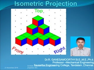
  • 1. Dr.R. GANESAMOORTHY.B.E.,M.E.,Ph.d. Professor –Mechanical Engineering Saveetha Engineering College, Tandalam ,Chennai. 21 November 2018 1 Dr.RGM, Professor/ Mechanical/ isometric projection /EG
  • 2. What is Isometric view The isometric view represents the overall appearance of the object and makes it easy to understand some details which may be difficult to understand in the orthographic projections. Isometric View: The three dimensional view of an object obtained on a plane of projection in which all the projectors are parallel but inclined at an angle of 300 to the plane of projection is known as Isometric View. 21 November 2018 2Dr.RGM, Professor/ Mechanical/ isometric projection /EG
  • 3. Isometric Scale Isometric scale: The proportion by means of which the true distances are reduced to isometric distance is known as Isometric Scale. Construction Method of Isometric Scale: To get accuracy in the Isometric projections, it is necessary to get isometric lengths from the true lengths. 21 November 2018 3Dr.RGM, Professor/ Mechanical/ isometric projection /EG
  • 4. Isometric Scale This can be done by constructing the Isometric Scale, Construction steps are: 1. Draw a horizontal line AB 2. At point A, Draw a line AC at angle 450 as shown in the following figure 3. At point A, Draw another line AD at angle 300 as shown in the following figure. 4. Now mark the true lengths such as 1, 2, 3, 4, 5, 6 cm etc on the line AC. 5. Project points 1, 2, 3, 4, 5, 6 etc on line AD so that projectors are perpendicular to the line AB. 6. Corresponding points on line AD, represents isometric lengths 1, 2, 3, 4, 5, 6 cm etc from the point A. 21 November 2018 4Dr.RGM, Professor/ Mechanical/ isometric projection /EG
  • 5. Difference between Isometric view and Isometric projection 21 November 2018 5Dr.RGM, Professor/ Mechanical/ isometric projection /EG S.No. Isometric View Isometric Projection 1 Drawn to actual scale Drawn to isometric scale 2 When lines are drawn parallel to isometric axes, the true lengths are laid off When lines are drawn parallel to isometric axes, the lengths are foreshortened to 0.82 time the actual lengths.
  • 6. objective of Isometric Objectives At the end of this session, you will be able to: 1. Show the length, width and height of an object in a single view. 2. Create a three-dimensional effect of an object by means of an isometric drawing. Points to be remembered while drawing isometric drawings At every visible corner of the object three lines must converge, of these three lines, either all the three or any two lines may be visible. 1. The hidden lines may not be shown, but it is advisable to check every corner, so that no visible line is left out. 2. Two outlines will never cross each other. 3. If the axis of the solid is vertical, its end or ends will be horizontal and if the axis of the solid is horizontal, its end or ends will be vertical. 21 November 2018 6Dr.RGM, Professor/ Mechanical/ isometric projection /EG
  • 7. Method of Isometric Projection Box method The isometric projections of prisms, squares and cylinders are generally drawn by the Box method. Co - ordinate or offset method The isometric projections of pyramids and cones are generally drawn by Co-ordinate or offset method. 21 November 2018 Dr.RGM, Professor/ Mechanical/ isometric projection /EG 7
  • 8. Isometric Projection of Planes 21 November 2018 Dr.RGM, Professor/ Mechanical/ isometric projection /EG 8 Rectangle
  • 9. Isometric Projection of Planes 21 November 2018 Dr.RGM, Professor/ Mechanical/ isometric projection /EG 9 Square
  • 10. Isometric Projection of Planes 21 November 2018 Dr.RGM, Professor/ Mechanical/ isometric projection /EG 10 Pentagonal Plane
  • 11. Isometric Projection of Planes 21 November 2018 Dr.RGM, Professor/ Mechanical/ isometric projection /EG 11 Circular Plane
  • 12. Isometric Projection of solids 21 November 2018 Dr.RGM, Professor/ Mechanical/ isometric projection /EG 12 1.Draw the isometric view of a square prism of side of base 30mm and height 55mm when its axis is vertical.
  • 13. Isometric Projection of solids 21 November 2018 Dr.RGM, Professor/ Mechanical/ isometric projection /EG 13 2. Draw the isometric view of a hexagonal pyramid of side of base 25 mm and height 60 mm, when it is resting on the HP, such that an edge of the base is parallel to the VP.
  • 14. Isometric Projection of solids 21 November 2018 Dr.RGM, Professor/ Mechanical/ isometric projection /EG 14 3 Draw the isometric view of a cylinder of 40 mm diameter and 60 mm height when it rests with one of its ends on the H.P.
  • 15. Isometric Projection of solids 21 November 2018 Dr.RGM, Professor/ Mechanical/ isometric projection /EG 15 4. Draw the isometric view of a cone of base 45 mm diameter and height 65mm when it rests with its base on the HP.
  • 16. Isometric Projection of solids 21 November 2018 Dr.RGM, Professor/ Mechanical/ isometric projection /EG 16 5. A hemisphere of 50mm diameter is nailed to the top face of the frustum of a hexagonal pyramid. The edges of the top and bottom faces of the frustum are 20mm and 35mm each respectively and the height of the frustum is 55mm. The axes of both the solids coincide. Draw the isometric view of the compound solid.
  • 17. Isometric Projection of solids 21 November 2018 Dr.RGM, Professor/ Mechanical/ isometric projection /EG 17 6.Draw the isometric view of a hexagonal prism of side base 30 mm and height 70 mm when its rests with its base on HP
  • 18. Isometric Projection of solids 21 November 2018 Dr.RGM, Professor/ Mechanical/ isometric projection /EG 18 7.Draw the isometric view of a hexagonal pyramid of side base 30 mm and height 65 mm, when it is resting on HP such that an edge of the base is parallel to VP.
  • 19. Isometric Projection of solids 21 November 2018 Dr.RGM, Professor/ Mechanical/ isometric projection /EG 19 8. A hexagonal prism of base side 30 mm and height 65 mm has a square hole of side 20 mm at the centre. The axes of the square and hexagon coincide. One of the faces of the square hole is parallel to a face of the hexagon. Draw the isometric view of the square prism with hole to full scale.
  • 20. Isometric Projection of solids 21 November 2018 Dr.RGM, Professor/ Mechanical/ isometric projection /EG 20 9. Draw the isometric view of a frustum of a hexagonal pyramid when it is resting on its base on the HP with two sides of the base parallel to the VP. The side of base is 20 mm and top 8 mm. The height of the frustum is 55 mm.
  • 21. Isometric Projection of solids 21 November 2018 Dr.RGM, Professor/ Mechanical/ isometric projection /EG 21 10.Draw the isometric view of a frustum of a square pyramid .The side of base is 40 mm and top 20 mm. The height of the frustum is 60 mm.
  • 22. Isometric Projection of solids 21 November 2018 Dr.RGM, Professor/ Mechanical/ isometric projection /EG 22 11. A square pyramid of base side 25 mm and height 50 mm has resting on HP with its base. It is cut by a cutting plane inclined at 350 to HP and bisecting the axis. Draw the isometric view.
  • 23. Isometric Projection of solids 21 November 2018 Dr.RGM, Professor/ Mechanical/ isometric projection /EG 23 12.A cylinder base diameter 35 mm and height 55 mm resting on HP with its base. It is cut by a cutting plane perpendicular to VP and inclined to HP at 450 and meeting the axis at 15 mm from the top end. Draw the isometric view of the truncated solid.
  • 24. Isometric Projection of solids 21 November 2018 Dr.RGM, Professor/ Mechanical/ isometric projection /EG 24 13. Draw the isometric view of a pentagonal pyramid 30 mm edge of base and 65 mm height resting on HP such that an edge of the base is parallel to VP and nearer to it and cut by a section plane perpendicular to VP and inclined at 300 to HP passing through a point on the axis at a height of 35 mm from the base.
  • 25. Isometric Projection of solids 21 November 2018 Dr.RGM, Professor/ Mechanical/ isometric projection /EG 25 14.Draw the isometric view of a pentagonal prism 30 mm edge of base and 65 mm height resting on HP and one of it is base one of the edges of base is perpendicular to VP. The prism is cut by a plane perpendicular to VP and inclined at 300 to HP and intersect the axis at 15 mm from the top.
  • 26. Isometric Projection of solids 21 November 2018 Dr.RGM, Professor/ Mechanical/ isometric projection /EG 26 15. A cone of the base diameter 40 mm and axis height 50 mm resting on HP with base. It is cut by section plane inclined at 450 to HP and bisecting the axis. Draw the isometric view.
  • 27. Isometric Projection of solids 21 November 2018 Dr.RGM, Professor/ Mechanical/ isometric projection /EG 27 16. The frustum of a pentagonal pyramid base 30 mm side and top face 15 mm side has a height of 40 mm. Draw its isometric view.
  • 28. Isometric Projection of solids 21 November 2018 Dr.RGM, Professor/ Mechanical/ isometric projection /EG 28 17.Draw its isometric view of a frustum of a cone base 60 mm side and top face 35 mm side has a height of 50 mm.
  • 29. Isometric Projection of solids 21 November 2018 Dr.RGM, Professor/ Mechanical/ isometric projection /EG 29 18.A cylinder of 50 mm and diameter and 60 mm height stands on HP. A section plane perpendicular to VP inclined at 550to HP cuts the cylinder and passing through a point on the axis at a height of 45 mm above the base. Draw the isometric view of the truncated portion of the cylinder such that the cut surface is clearly visible to the observer.
  • 30. Isometric Projection of solids 21 November 2018 Dr.RGM, Professor/ Mechanical/ isometric projection /EG 30 19.A dust bin is in the form of a frustum of a hollow square pyramid with the base dimensions of 20 mm sides and the top open surface of 45 mm sides. Draw the isometric view of the hollow dust bin, if its height is 50 mm and the wall thickness of negligible.
  • 31. Isometric Projection of solids 21 November 2018 Dr.RGM, Professor/ Mechanical/ isometric projection /EG 31 20.A waste paper bucket is in the form of a frustum of hexagonal pyramid of side of base 180 mm and top 300 mm side. Height is 400 mm. Draw the isometric view. Take suitable scale.
  • 32. Isometric Projection of solids 21 November 2018 Dr.RGM, Professor/ Mechanical/ isometric projection /EG 32 21. A cone of base diameter 30 mm and height 40 mm rests centrally over a frustum of a hexagonal pyramid of base side 40 mm top 25 mm and 60 mm height. Draw the isometric view of the solid.
  • 33. Isometric Projection of solids 21 November 2018 Dr.RGM, Professor/ Mechanical/ isometric projection /EG 33 22. A square pyramid of side 30 mm axis length 50 mm is centrally placed on top of a cube of side 50 mm. Draw the isometric view of solid
  • 34. Isometric Projection of solids 21 November 2018 Dr.RGM, Professor/ Mechanical/ isometric projection /EG 34 23. A hexagonal shaped solid of base edge 20 mm and height 40 mm lies centrally on a cylinder of 60 mm diameter and 20 mm thick. Draw the isometric view of the solids if their axes lie on the same line.
  • 35. Isometric Projection of solids 21 November 2018 Dr.RGM, Professor/ Mechanical/ isometric projection /EG 35 24. A square slab of 60 x 60 x 20 resting on HP with one of its sides parallel to VP.A truncated cone of 50 mm bottom base diameter 40 mm top face diameter and 50 mm height placed centrally over the slab. A hemisphere of 30 mm radius placed over the top face of the truncated cone centrally. Draw the isometric view of the solids.
  • 36. Isometric Projection of solids 21 November 2018 Dr.RGM, Professor/ Mechanical/ isometric projection /EG 36 25. A circular slab of 60 mm diameter and 30 mm height resting on HP with one of the base. A cube of 30 mm side is placed over the circular slab centrally. A square pyramid of base side 20 mm and axis height 20 mm placed centrally over the cube. Draw the isometric view.
  • 37. Isometric Projection of solids 21 November 2018 Dr.RGM, Professor/ Mechanical/ isometric projection /EG 37 26. A frustum of a cone has its top and bottom diameters 35 mm and 50 mm respectively and altitude 53 mm. It rests on the top face of the frustum of a square pyramid. The sides of the top and bottom faces of the pyramid are 58 mm and 70 mm respectively. The height is 22 mm, Draw the isometric view.
  • 38. Isometric Projection of solids 21 November 2018 Dr.RGM, Professor/ Mechanical/ isometric projection /EG 38 27. A frustum of the conical solid of the base diameter 50 mm and top diameter 26 mm and 50 mm height is placed centrally over a cylindrical block of 76 mm base diameter and axis 25 mm long. The axes of the two solids as collinear. Draw the isometric view of the combined solids.
  • 39. Isometric Projection of solids 21 November 2018 Dr.RGM, Professor/ Mechanical/ isometric projection /EG 39 28. A sphere of diameter 40 mm is kept centrally over a square slab of 60 mm side and 25 mm height. Draw the isometric projection of the solid.
  • 40. Isometric Projection of solids 21 November 2018 Dr.RGM, Professor/ Mechanical/ isometric projection /EG 40 29. A square pyramid rests centrally over a cylindrical block. Draw the isometric projection of the arrangement. Consider a pyramid has a base with 25 mm side and 40 mm long axis whereas the cylindrical block has a base with 50 mm diameter and 20 mm thickness.
  • 41. Method of Isometric Projection Box method The isometric projections of prisms, squares and cylinders are generally drawn by the Box method. Co - ordinate or offset method The isometric projections of pyramids and cones are generally drawn by Co-ordinate or offset method. 21 November 2018 Dr.RGM, Professor/ Mechanical/ isometric projection /EG 41
  • 42. Parallel-line Developments Parallel-line developments are made from common solids that are composed of parallel lateral edges or elements. e.g. Prisms and cylinders The cylinder is positioned such that one element lies on the development plane. The cylinder is then unrolled until it is flat on the development plane. The base and top of the cylinder are circles, with a circumference equal to the length of the development. All elements of the cylinder are parallel and are perpendicular to the base and the top. 21 November 2018 42Dr.RGM, Professor/ Mechanical/ isometric projection /EG
  • 43. Parallel-line Developments 21 November 2018 43Dr.RGM, Professor/ Mechanical/ isometric projection /EG
  • 44. Radial-line developments Radial-line developments are made from figures such as cones and pyramids. In the development, all the elements of the figure become radial lines that have the vertex as their origin. The cone is positioned such that one element lies on the development plane. The cone is then unrolled until it is flat on the development plane. One end of all the elements is at the vertex of the cone. The other ends describe a curved line. The base of the cone is a circle, with a circumference equal to the length of the curved line. 21 November 2018 44Dr.RGM, Professor/ Mechanical/ isometric projection /EG
  • 45. Radial-line developments 21 November 2018 45Dr.RGM, Professor/ Mechanical/ isometric projection /EG
  • 46. Triangulation developments 21 November 2018 46Dr.RGM, Professor/ Mechanical/ isometric projection /EG Triangulation developments are made from polyhedrons, single curved surfaces, and wrapped surfaces. The development involve subdividing any ruled surface into a series of triangular areas. If each side of every triangle is true length, any number of triangles can be connected into a flat plane to form a development Triangulation for single curved surfaces increases in accuracy through the use of smaller and more numerous triangles. Triangulation developments of wrapped surfaces produces only approximate of those surfaces.
  • 47. Triangulation developments 21 November 2018 47Dr.RGM, Professor/ Mechanical/ isometric projection /EG .
  • 48. Approximate developments 21 November 2018 48Dr.RGM, Professor/ Mechanical/ isometric projection /EG .Approximate developments are used for double curved surfaces, such as spheres. Approximate developments are constructed through the use of conical sections of the object. Approximate developments the material of the object is then stretched through various machine applications to produce the development of the object.
  • 49. Development of surfaces – Prism Problems 21 November 2018 49Dr.RGM, Professor/ Mechanical/ isometric projection /EG 1. A Square prism of base side 40 mm and axis length 50 mm is resting on HP on one of its base with a side of base inclined at 35 0 to VP. It is cut by a plane inclined at 300 to HP and perpendicular to VP and is bisecting the axis. Draw the development of the remaining portion of the prism.
  • 50. Development of surfaces – Prism Problems 21 November 2018 50Dr.RGM, Professor/ Mechanical/ isometric projection /EG 2. A pentagonal prism of base side 25 mm and height 55 mm is cut by a plane perpendicular to VP and 300 to HP and passing through the axis 30 mm above the base, draw the lateral surfaces development in the lower portion of the solid.
  • 51. Development of surfaces – Prism Problems 21 November 2018 51Dr.RGM, Professor/ Mechanical/ isometric projection /EG 3. A pentagonal prism of base side 25 mm and height 60 mm is resting on the ground with one of its base edge parallel to VP . Find graphically the shortest distance of the string which connect one end of the lateral edge with the other end of the same edge, covering all the lateral surfaces of the solid. Also trace the points on the development.
  • 52. Development of surfaces – Prism Problems 21 November 2018 52Dr.RGM, Professor/ Mechanical/ isometric projection /EG 4. A hexagonal prism of base side 30 mm and height 60 mm is resting on the ground with one of its vertical faces perpendicular to VP .It is cut by a plane inclined at 500 to HP and perpendicular to VP and meets the axis of the prism at a distance of 10 mm from the top end. Draw the development of the lateral surfaces.
  • 53. Development of Surfaces – Cylinder Problems 21 November 2018 53Dr.RGM, Professor/ Mechanical/ isometric projection /EG 5. Draw the development of the lateral surfaces of the lower portion of a cylinder of diameter 45 mm and height 60 mm when sectioned by a plane inclined at 400to HP and perpendicular to VP and bisecting the axis.
  • 54. Development of Surfaces – Cylinder Problems 21 November 2018 54Dr.RGM, Professor/ Mechanical/ isometric projection /EG 6. A cylinder of diameter 50 mm and axis height 65 mm is cut by a plane inclined at 600 to the HP and bisecting the axis. Draw the development of the lateral surfaces
  • 55. Development of Surfaces – Cylinder Problems 21 November 2018 55Dr.RGM, Professor/ Mechanical/ isometric projection /EG 7. A cylinder of diameter 40 mm and axis height 75 mm is cut by a plane perpendicular to VP inclined at 550 to HP meeting the axis at the top face. Draw the development of the lateral surfaces of solid.
  • 56. Development of Surfaces – Pyramids Problems 21 November 2018 56Dr.RGM, Professor/ Mechanical/ isometric projection /EG 8. A pentagonal pyramid of base 25 mm side and height 65 mm stands with its base on the HP such that one of its base edges is parallel to the VP. It is cut by a section plane perpendicular to the VP and inclined at 300 to the HP, bisecting the axis. Draw the development of the lateral surfaces of solid.
  • 57. Development of Surfaces – Pyramids Problems 21 November 2018 57Dr.RGM, Professor/ Mechanical/ isometric projection /EG 9.A pentagonal pyramid of base 25 mm side and height 60 mm lying on the HP on its base such that one of its base edges is parallel to and far away from the VP. It is cut by a section plane one is perpendicular to the VP and inclined at 400 to the HP, and meeting the axis at 14 mm from the base the other plane is parallel to HP and perpendicular to VP meeting the axis distance of 28 mm from the base. Draw the development of the lateral surfaces of solid.
  • 58. Development of Surfaces – Pyramids Problems 21 November 2018 58Dr.RGM, Professor/ Mechanical/ isometric projection /EG 10. A square pyramid of base side 30 mm and altitude 65 mm is resting on HP on its base with a side of the base inclined at 250 to VP. It is cut by a plane inclined 350 to HP and perpendicular to VP and bisects the axis. Draw the development of the remaining surfaces of solid.
  • 59. Development of Surfaces – Pyramids Problems 21 November 2018 59Dr.RGM, Professor/ Mechanical/ isometric projection /EG 11. A hexagonal pyramid of base 25 mm side and height 50 mm rests on its base with one base edge parallel to VP.A string is wound around the surfaces of the pyramid starting from the left extreme point of the base and ending at the same. Find the shortest length of the string required. Also trace the path of the string in the projection.
  • 60. Development of Surfaces – Pyramids Problems 21 November 2018 60Dr.RGM, Professor/ Mechanical/ isometric projection /EG 12. A hexagonal pyramid of base side 25 mm and altitude 60 mm is resting vertically on its base on the ground with two of the of the sides of the base perpendicular to the VP. It is cut by a plane perpendicular to the VP and inclined at 450 to the HP. The plane bisects the axis of the pyramid. Draw the development of the lateral surfaces of solid.
  • 61. Development of Surfaces – Pyramids Problems 21 November 2018 61Dr.RGM, Professor/ Mechanical/ isometric projection /EG 13.A square pyramid of base side 30 mm and height 50 mm rests on its base on the HP, with a base edge parallel to VP. It is cut by a plane perpendicular to VP and inclined 500to HP meeting the axis 30 mm above HP. Draw the development of the lateral surfaces.
  • 62. Development of Surfaces – Pyramids Problems 21 November 2018 62Dr.RGM, Professor/ Mechanical/ isometric projection /EG 14. A pentagonal pyramid of base 30 mm side and height 60 mm stands with its base on the HP on its base edges is perpendicular to the VP. It is cut by a section plane perpendicular to the VP and parallel to the HP, and meets the axis at a distance of 25 mm from the vertex. Draw the development of the lateral surfaces of solid.
  • 63. Development of Surfaces – Pyramids Problems 21 November 2018 63Dr.RGM, Professor/ Mechanical/ isometric projection /EG 15. A hexagonal pyramid of side of base 30mm and altitude 75 mm rests on its base on HP, such that a base edge is parallel to VP. it is cut by two cutting planes perpendicular to VP. One of the planes is inclined at 300 to HP and meeting the axis at a point 40 mm from the base. The other plane is curved of 30 mm radius with the right corner of the base as centre. Draw the development of the lateral surfaces.
  • 64. Development of Surfaces – Pyramids Problems 21 November 2018 64Dr.RGM, Professor/ Mechanical/ isometric projection /EG 16. A square pyramid of base side 35 mm and height 70 mm rests on its base on the HP, such that two adjacent sides of the base are equally inclined to VP. It is sectioned by a plane perpendicular to VP, inclined 300to HP and passing through the midpoint of the axis. Draw the development of the lateral surfaces.
  • 65. Development of Surfaces – Pyramids Problems 21 November 2018 65Dr.RGM, Professor/ Mechanical/ isometric projection /EG 17. Draw the development of the lateral surfaces of a hexagonal pyramid with a 40 mm base side and a 60 mm long axis ,which is resting on the base in the HP such that an edge of the base is perpendicular to VP when an auxiliary inclined plane whose VT makes on angle 600 HP and bisecting the axis.
  • 66. Development of surfaces – Cone Problems 21 November 2018 66Dr.RGM, Professor/ Mechanical/ isometric projection /EG 18. A cone of base side 60mm and height 70 mm rests on its base on the HP, It is sectioned by a plane perpendicular both HP and VP, and 10 mm away from the axis. Draw the development of the lateral surfaces.
  • 67. Development of surfaces – Cone Problems 21 November 2018 67Dr.RGM, Professor/ Mechanical/ isometric projection /EG 19. A cone of base side 50 mm and height 65 mm rests on its base on the HP, It is sectioned by a plane perpendicular VP and inclined at 300 to HP bisect the axis of the cone. Draw the development of the lateral surface.
  • 68. Development of surfaces – Cone Problems 21 November 2018 68Dr.RGM, Professor/ Mechanical/ isometric projection /EG 19. A cone of base side 50 mm and height 65 mm rests on its base on the HP, It is sectioned by a plane perpendicular VP and inclined at 300 to HP bisect the axis of the cone. Draw the development of the lateral surface.
  • 69. Development of surfaces – Cone Problems 21 November 2018 69Dr.RGM, Professor/ Mechanical/ isometric projection /EG 20.A right circular cone of diameter 50 mm axis height 60 mm is string on the ground with its base. Calculate the shortest length of a string required to wound round the lateral surface of the solid starting from one extreme point and ending at the same point. Also trace the points on to the projections.
  • 70. Development of surfaces – Cone Problems 21 November 2018 70Dr.RGM, Professor/ Mechanical/ isometric projection /EG 21. A cone of base side 50 mm and height 75 mm rests on its base on the HP, It is sectioned by a plane perpendicular VP and parallel to HP at a distance 20 mm from the vertex. It is also cut by a plane inclined at 400to the base and meeting the axis at a point 22 mm above the base. Draw the development of the lateral surface.
  • 71. Development of surfaces – Cone Problems 21 November 2018 71Dr.RGM, Professor/ Mechanical/ isometric projection /EG 22.A cone of base side 45 mm and height 70 mm rests on its base on the HP, It is sectioned by a plane perpendicular VP 300to HP and bisecting the axis. Draw the development of the lateral surfaces
  • 72. Development of surfaces – Cone Problems 21 November 2018 72Dr.RGM, Professor/ Mechanical/ isometric projection /EG 23. A cone of base side 50 mm and height 60 mm rests on its base on the HP, It is sectioned by a plane perpendicular VP ,parallel to one of the generators and passing through a point on the axis at a distance of 22 mm from the apex. Draw the development of the lateral surfaces
  • 73. Development of surfaces – Special Problems 21 November 2018 73Dr.RGM, Professor/ Mechanical/ isometric projection /EG 24. Draw the development of the tray whose pictorial view as shown in fig Step:1 Step:2
  • 74. Development of surfaces – Special Problems 21 November 2018 74Dr.RGM, Professor/ Mechanical/ isometric projection /EG 25. Draw the development of a duct as shown.
  • 75. Development of surfaces – Special Problems 21 November 2018 75Dr.RGM, Professor/ Mechanical/ isometric projection /EG 26. Draw the development of the three pipes forming a Y shape as shown. All the pipes are diameters of 40 mm. The max. Height of the vertical pipe is 50 mm. The angle between the axes of the inclined pipes is 800.
  • 76. Development of surfaces – Special Problems 21 November 2018 76Dr.RGM, Professor/ Mechanical/ isometric projection /EG 27. An offset fitting is made up of three pipes of diameter 40 mm each. The total length of the fitting is 90 mm and the offset is 55 mm. Draw the lateral surface of the pipes.
  • 77. Development of surfaces – Special Problems 21 November 2018 77Dr.RGM, Professor/ Mechanical/ isometric projection /EG 28. An elbow is made up of three pipes are diameter 40 mm each fitted as shown. The shorter arm of both the vertical and horizontal pipes has the same length of 20 mm. Draw the development of pipes forming the elbow.
  • 78. Development of surfaces – Special Problems 21 November 2018 78Dr.RGM, Professor/ Mechanical/ isometric projection /EG 29. A funnel is made up of a truncated cone and a cut cylinder as shown. The cone is of base diameter 60 mm and altitude 70 mm. They are fitted as shown. Draw the development of funnel forming cone.