
Empfohlen
Weitere ähnliche Inhalte
Was ist angesagt?
Was ist angesagt? (20)
Ähnlich wie Ultrasound assignment 3 mark question and answer
Ähnlich wie Ultrasound assignment 3 mark question and answer (20)
Mehr von Ganesan Yogananthem
Mehr von Ganesan Yogananthem (17)
Kürzlich hochgeladen
Kürzlich hochgeladen (20)
Ultrasound assignment 3 mark question and answer
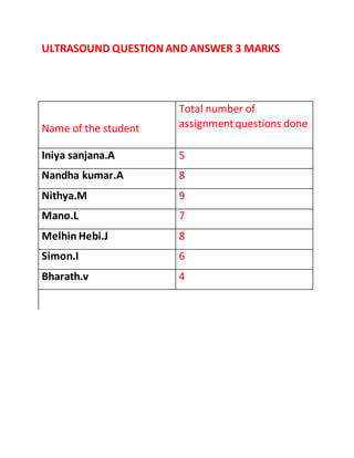
- 1. ULTRASOUND QUESTION AND ANSWER 3 MARKS Name of the student Total number of assignmentquestions done Iniya sanjana.A 5 Nandha kumar.A 8 Nithya.M 9 Mano.L 7 Melhin Hebi.J 8 Simon.I 6 Bharath.v 4
- 2. 1.Brightness mode ( by Sanjana) Two dimensional 2D slice of anatomy of the patient is imaged.B-Mode is a two-dimensional ultrasound image display composed of bright dots representing the ultrasound echoes. The brightness of the dot is proportional to echo intensity. To create a 2D display, the transducer is moved back and forth and echoes are collected as dots from the patient. Thousands of such dots of varying brightness give the grey scale image. The B- mode made the ultrasound as a diagnostic tool, especially in abdominal diseases. It provides a picture of a slice of tissue. Since sweeping motion refers to sector it is known as sector scanning.
- 3. 2.Types of Doppler ultrasound: by Iniya Sanjana Doppler ultrasound is useful to investigate variation of blood flow in arteries and veins. Types of Doppler ultrasound: 1, Continuous Doppler. Continuous transmissionand reception of ultrasound waves. This is accomplished by two dedicated transducer elements: one that solely sends a signal and another that only receives.
- 4. 2 Pulsed Doppler. Pulsed Doppler combines continuous wave Doppler and pulse echo imaging. The former gives velocity and the later gives depth information.
- 5. 3 Duplex scanning The term "duplex" refersto the fact that two modes of ultrasound are used, Doppler and B-mode. Duplex ultrasound involves using high frequency sound waves to look at the speed of blood flow, and structure of the leg veins.
- 6. 4 Color Doppler Color Doppler is a technique in which colors are superimposed on an image of a blood vessel indicate the speed and direction of blood flow in the vessel.
- 7. 5. Power Doppler Power Doppler sonography is a new technique that displays the strength of the Doppler signal in color, rather than the speed and direction information. It has three times the sensitivity of conventional color Doppler, for detection of flow and is particularly useful for small vessels and those with low-velocity flow.
- 8. 3.Fraunhofer zone or far field( by Sanjana) • Fraunhofer zone or far field is one, in which the beam diverges and obey sin ø=1.22 y/d where ø is the beam divergence, d is transducer effective diameter. • Less beam divergence occurs with high frequency and with large diameter Crystals. • The us intensity decreases with distance. • The beam intensity falls off in both zones, due to attenuation, and in the far zone because of beam divergence. • Normally Fresnel zone is used for imaging, because the resolution is poor in Fraunhofer zone.
- 9. 4.Clinical probes ( by Sanjana) The transducers are also made to suit the individual clinical applications. The clinical probes are as follows: • Endo vaginal – pelvic region • Endorectal – prostate • Transoesophageal – heart • Intravascular – blood vessels.
- 10. 1.Time Gain Compensation ( by Sanjana) The time gain compensation, TGC, amplify the signal proportional to the time delay between transmissionand detection of US pulses. Generally, US imaging is done with pulses of 1 ms duration. There is enough time in between two pulses to receive echoes. The tissues are larger in size compared to US wavelength and also in different depths. Though, echoes give information about the tissues, but are highly attenuated and signal is weak. Hence scanner circuit amplify and digitise the signal, and use Time gain Compensation (TGC) to compensate attenuation.
- 11. 6.ACOUSTIC IMPEDANCE (by Nandha kumar) Acoustic impedance is a physical property of tissue. It describes how much resistance an ultrasound beam encounters as it passes through a tissue. Acoustic impedance depends on: The density of the tissue (d, in kg/m3) The speed of the sound wave (c, in m/s) o They are related by: Z = d x c So, if the density of a tissue increases, impedance increases.
- 12. 7.DRAW A NEAT DIAGRAM OF ULTRASOUND TRANSDUCER ( By Nandha kumar )
- 13. 8.IMAGE FORMATION IN ULTRASOUND (by Nandha kumar) Ultrasound machine, with patient adjacent to sonographer, who is adjusting the machine in order to optimize image quality. Within the piezoelectric crystals or ceramic of the transducer, energy is converted from electrical to mechanical energy. It uses a smallprobe called a transducer and gel placed directly on the skin. High-frequency sound waves travel from the probe through the gel into the body. The probe collects the returning reflected US waves are the basis for image formation. A computer uses those sound waves to create an image.
- 14. 9.WRITE ANY THREE COMMON ULTRASOUND ARTIFACT (By Nandha kumar) BEAM WIDTH ARTEFACTS : Caused due to the widening of the main beam after the focal spot SIDE LOBE ARTEFACTS Side lobes are multiple beams of low-amplitude ultrasound energy that project radially from the main beam axis, mainly seen in linear array transducer.
- 15. COMET TAIL ARTEFACTS : Comet tail artefact is a form of reverberation. In this artefact, the two reflective interfaces and thus sequential echoes are closely spaced. On the display, the sequential echoes may be so close together that individual signals are not perceivable. • In addition the later echoes may have decreased amplitude secondary to attenuation; this decreased amplitude is displayed as decreased width.
- 16. 10.WHAT IS ULTRASOUND? HOW IT IS PRODUCED ( By Nandhakumar ) Ultrasound describes sound waves of frequency exceeding the range of human hearing (> 20 kHz). In medicine the ultrasound energy and the acoustic properties of the body, produce image from stationary and moving bodies. Diagnostic ultrasound uses 1-20 MHz frequency and the velocity depends on the nature of medium through which it travel and independent of frequency
- 17. A transducer with piezoelectric crystals(quartz crystal ) is used to produce the ultrasound beam. This is a material in which mechanical energy is converted into electrical energy and vice versa. This means that transmitting an electric voltage through the material will cause it to vibrate, producing a sound wave. Similarly, the returning echo sound wave vibrates the crystals producing an electric voltage that can be measured. In this way, the material acts as a receiver and a transmitter. Piezoelectricity is the electricity generated by piezo element by effect called the piezoelectric effect. It is
- 18. the ability of certain materials to generate an AC (alternating current) voltage when subjected to mechanical stress or vibration, or to vibrate when subjected to an AC voltage, or both. Some examples of piezoelectric materials are PZT (also known as lead zirconate titanate), barium titanate, and lithium niobate. These man-madematerials have a more pronounced effect (better material to use) than quartz and other natural piezoelectric materials. 11.PHASED ARRAY TRANSDUCER (by Nandhakumar) • The transducer is named after the piezoelectric crystals arrangements which is called Phased array and it is the most commonly used crystal Phased array transducer has a small footprint and low frequency (its central frequency is 2 Mhz – 7.5 Mhz) • The beam point is narrow but it expands depending on the applied frequency. Furthermore, the beam shape is almost triangular and the near- field resolution is poor Use this transducer for various application such as • Cardiac examinations
- 19. • Abdominal examinations • Brain examinations 12. Reverberationartifact in ultrasonography (by Nandha kumar) Reverberation artifact is a common ultrasound artifact and occurs when a sound pulse reverberates back and forth between two strong parallel reflectors. With the exception of comet-tail artifact, a subtype of reverberation, reverberation artefact has little diagnostic use. The artifact can be improved by changing the angle of insonation. If the angle is changed, the pulse is reflected
- 20. off at an angle and either a) does not encounter the second parallel strong reflector, or b) is reflected away from the transducer. 13.Role of ultrasound in obstetrics ( by Nandhakumar) • Ultrasound as a diagnostic tool. A screening test is one that is used to assess the risk of a particular outcome • Ultrasound can also be used to screen an obstetric population to diagnose a fetal problem. • The widest use of ultrasound in obstetrics is in the diagnosis of fetal malformation. • The clinical applications and uses of ultrasound include confirmation of pregnancy, localisation of placenta and monitoring of foetal wellbeing.
- 21. 14.Propagationof ultrasound waves in tissue ( by nithya) Ultrasound is produced by piezoelectric effect and it travels in straight line. It travels in a medium in the form of wave with compression and rarefaction. It has wavelength, frequency, velocity and amplitude. Wavelength is the distance between consecutive crests, frequency is the number of cycles per second and it is equal to 1/f. Diagnostic ultrasound uses 1-20 MHz frequency and the velocity depends on the characteristics of the medium and independent of frequency. It is inversely proportional to compressibility Sound waves travel faster in solids and slower in gases. The intensity of ultrasound is a measure of beam and is proportional to the square of amplitude.
- 22. 15.Pulse echo frequency (by nithya) Ultrasound transducer produces pulses of ultrasound waves. The number echo pulses received per second is known as pulse echo frequency. These waves travel within the body and interact with tissues by transducer. The reflected wave return to the transducer and processed by the ultrasound machine. An image which represents these reflections is formed on the monitor Pulsing is determined by the transducer or probe crystal and echoes are interpreted and processed by ultrasound machine
- 23. 16.Ultrasound transducer frequency (by nithya) Ultrasound frequencies in diagnostic radiology range from 2 MHz to approximately 15 MHz. higher frequencies of ultrasound have shorter wavelengths and are absorbed/attenuated more easily. Therefore, higher frequencies are not as penetrating. Higher frequencies are used for the superficial body structures and lower frequencies are used for those that are deeper. 2.5 MHz: deep abdomen, obstetric and gynecological imaging 3.5 MHz: general abdomen, obstetric and gynecological imaging 5.0 MHz: vascular, breast, pelvic imaging 7.5 MHz: breast, thyroid 10.0 MHz: breast, thyroid, superficial veins, superficial masses, musculoskeletal imaging.
- 24. 15.0 MHz: superficial structures, musculoskeletal imaging
- 26. 17.Patient positioning in ultrasound (by nithya) Keeping the body part to be scanned directly in front of the sonographer. We Instruct patients to orient themselves to assist the sonographer in using neutral postures while performing scans. For instance, while performing scans on the side of a patient, have them roll onto their side. We Instruct patients to move as close to the sonographer as possible during scans. Patient needs to Keeping the torso straight. Do not bend And Keeping the elbow bent at about 90 to 110 degrees and close to the body. Do not reach out and away from the body.
- 27. 18.Frequency and resolution( by nithya) Frequency- number of complete cycles per unit of time Units are hertz Ultrasound imaging frequency range is 2 -20 Mhz Resolution is the ability to identify two objects Wavelength (frequency) dependent it includes spatial and temporal resolution Lower the frequency higher the penetration and lower the resolution Higher the frequency lower the penetration and higher the resolution 19. Any one ultrasound artifact (by nithya) 1. Refractionartifact When us waves enter into one medium from another different medium, travelling direction is changing and this is known as refraction. • Refraction is the change of direction of the transmitted pulse. Refracted beam causes misregistration of echo, resulting in misplaced anatomy e.g. eyes and fatty tissues.
- 28. • Misplacement depends on the position of the transducer and angle of incidence with tissue boundaries. • It appears as misregistration, defocusing, and ghost images. • Misregistration cause improper placement, and distortion of size or shape. • Defocusing is due to loss of beam coherence, and cause shadowing at the edge of large curved structures • Ghost images are due to altered sound beam path
- 29. 20. basic principle of doppler imaging (by nithya) • In ultrasound, the Doppler effect is used to measure blood flow velocity • Ultrasound reflected from red blood cells will change in frequency according to the blood flow velocity and direction of flow. • When direction of blood flow is towards the transducer, the echoes from blood reflected back to the transducer will have a higher frequency that the one emitted from the transducer. • When the direction is away from the transducer, the echoes will have a lower frequency than those emitted. • The difference in frequency between transmitted and received echoes is called doppler frequency shift, and this shift in frequency is proportional to the blood flow velocity.
- 30. 21. Recent advanced in ultrasonography ( by nithya) • Wireless transducer- Is used to image from up to 10 feet away. And it can also be used to aid in vascular access procedures. • Shear wave elastography – SWE can record elasticity more accurately than conventional elastography and produce more objective, real time colour coded map to show tissue stiffness. • Tissue harmonic imaging – is a grayscale ultrasound mode based on the phenomenon of non linear distortion of acoustic signal. It improved axial resolution, better lateral resolution, less side lobes artifact, and better imaging option for obese patient. By using focused ultra sound waves we can treat fibroids in uterus.
- 31. 22. Spatial and temporal resolution(by nithya ) Resolution- Resolution is defined as the ability to distinguish echoes in term of space, time or strength. Temporal resolution- is the ability of an ultrasound system to accurately show changes in the underlying anatomy over time, this is particularly important in echocardiography Spatial resolution – is the ability of ultrasound to detect and display structures that are close together. There are two types of spatial resolution Axial& lateral Axial resolution - the ability to displays small targets along the path of the beam as separate entities. Lateral resolution – the ability to distinguish between two separate targets perpendicular to the
- 32. beam path, its depend upon the width of ultrasound transducer 23. WHAT ARE THE COMPONENTS OF ULTRASOUND MACHINE (BY MANO) Transducer probe : Probe is transmitter and receiver the sound wave. Central processing unit (CPU): Computer that does all of the calculation and contains the electrical power supplies for itself and the transducer probe. Display: Displays the images from the Ultrasound data processing by the CPU.
- 33. Keyboard: Input data and takes measurements from the display. Disk storage device: Store the acquired image. Printer: Prints the image from the displayed data. 24. What are the advantages and disadvantages of Ultrasound examinations. (by mano) ADVANTAGE Non invasive Non ionizing radiation is used Simple Real time imaging Portable machine Can repeat and easy to store DISADVANTAGES: Operator and equipment dependant Hard tissue cannot be imaged Deep structures cannot be visualized
- 34. 25. Write about the sector transducer. ( by mano) Sector transducers produce a fan-like image that is narrow as it leaves the transducer and increases with depth. It is ideal for imaging through small “windows” such as the cranial window in the temple, or between the ribs. They are commonly used for transcranial and cardiac imaging. These transducers provide good depth penetration, but have very poor near field resolution This transducer is named after the piezoelectric crystal arrangement which is called phased-array and it is the most commonly used crystal. Phased Array transducer has a small footprint and low frequency (its central frequency is 2Mhz – 7.5Mhz). The beam point is narrow but it expands depending on the applied frequency.
- 35. Furthermore, the beam shape is almost triangular (see picture below) and the near-field resolution is poor. Cardiac examinations Abdominal examinations Brain examinations 26. Write about the uses of transducer jelly.(by mano) Ultrasound gel is a conductive medium that creates a bond between the skin and the ultrasound transducer. The ultrasound sound waves have a hard time traveling through air, so the gel prevents any extra air space between the probe and your skin in order to create a clear image of the anatomy. Ultrasound requires an aqueous interface between the transducer and the skin
- 36. or else all you see is black. Ultrasound gel is a clear goo, looks like hair gel or aloe vera, and is made by several companies out of various combinations of propylene glycol, glycerine, perfume, dyes, phenoxyethanol or carbapol R 940 polymer along with lots of water. Ultrasound Gel – Alternatives are KY Jelly. One of the most common ultrasound gel alternatives, KY Jelly is a water-based and water-soluble product that is used as a personal lubricant. ... Bio Oil. ... Moisturizers & Creams. ... Hand Sanitizer. ... Skin Gel or Aloe Ver
- 37. 27. Write about the piezoelectricmaterial.(by mano) Piezoelectric materials are materials that have the ability to generate internal electrical charge from applied mechanical stress. Several naturally occurring substances in nature demonstrate the piezoelectric effect. These include: Bone Crystals (quartz ) Certain ceramics DNA Enamel Silk Dentin, and many more. Materials that exhibit the piezoelectric effect also demonstrate the inverse piezoelectric effect (also called the reverse or converse piezoelectric effect). The inverse piezoelectric effect is the internal generation of mechanical strain in response to an applied electrical field
- 38. 28. DEPTH RESOLUTION IN ULTRASONOGRAPHY. ( BY MANO) Deep resolution. The ability of an ultrasound system to distinguish between two points at a particular depth in tissue, that is to say, axial resolution and lateral resolution, is determined predominantly by the transducer. The lower frequency, at 2-6 MHz allows for deep penetration. The curved linear array transducer with frequency 2-6 MHz offers high resolution imaging for deep abdominal scanning. The curved linear array of the
- 39. transducer allows for a wider field view, and conformity to the abdominal area, making scanning patient and doctor friendly.
- 40. 29. FOCUSED TRANSDUCER . (by mano)
- 41. Beam focusing refers to creating a narrow point in the cross-section of the ultrasound beam called the focal point. It is at the focal point where the lateral resolution of the beam is the greatest also. Before the focal point is the near field or Fresnel zone, where beams converge. Distal to this focal point is the far field or Fraunhofer zone where beams diverge. 30. Write about beam width artifact. (J. Melhin) Caused due to the widening of the main beam after the focal spot. The ultrasound image localization software assumes an imaging plane as indicated by the dotted lines. Echoes generated by the object located in the peripheral field ( gray circle) are displayed as overlapping the object of interest (white square).
- 42. 31.DOPPLER EFFECT (J. Melhin) The Doppler effect (or Doppler shift) is the change in frequency of a wave in relation to an observer who is moving relative to the wave source. In medical ultrasound the Doppler effect is used to measure the velocity of blood in blood vessels, especially arteries to determine if a stenosis is present. The Doppler equation is modified when used for medical ultrasound to take into account the pulse–echo cycle , as each part produces a Doppler shift .
- 43. 32.Reflectionof ultrasound with matter. ( J. Melhin) Reflection is divided into specular and non– specular reflection. A specular reflection is one in ultrasound strike a large smooth boundary , where structure size >structure size > lambda. This is major contributor of ultrasound imaging . Non specular reflection is one in which the ultrasound strikes a irregular boundary, where the irregular boundary /structure size is < lambda. When sound wave travels from a medium of low Z to medium of high Z , reflection occurs and it obeys Snell ‘s law¦ n1 and n2 are velocity of ultrasound in the medium.
- 45. 33. Relationship between resonance frequency and crystal thickness. (J. Melhin) The frequency is inversely proportional to crystal thickness. Changing the thickness of the crystal changes the frequency but not the ultrasound amplitude ( determined by applied voltage waveform) or speed ( determined by piezoelectric crystal). High frequency transducers are thin and low frequency transducers are thicker. To change the frequency one has to change the transducer.
- 46. 34.Write about resonance and non resonance transducer. (J. Melhin) Resonant transducer: Resonant type transducers follow relation =2T,where T is the thickness of the crystal. It is used in pulse echo ultrasound imaging. High frequency transduce requires thinner crystals and low frequency requires thicker crystals. Non resonant transducer: Non resonant transducers are made by machining a piezoelectric material. The matching layer thickness is less. It will produce multiple frequency.
- 47. 35.Write about reverberationartifact.( J. Melhin) Appearance : Multiple equidistantly spaced linear reflections, ladder. Physics: Parallel highly reflective surfaces, the echoes generated from a primary US beam may be repeatedly reflected back and forth before returning to the transducer for detection. Prevention: # decrease TGC near in the near gain.
- 48. # change beam angle /alternative window. 36. Role of frequency in imaging. (J. Melhin) Ultrasound waves have frequencies that exceed the upper limit for audible human hearing ,i.e ., greater than 20 kHz. Medical ultrasound devices use sound waves in the range of 1–20 MHz. Proper selection of transducer frequency is an important concept for providing optimal image resolution in diagnostic and procedural ultrasound.
- 49. High frequency ultrasound waves (short wavelength) generate images of high axial resolution. Low frequency waves (long wavelength) generate images of lower resolution. High frequency =high spatial resolution but limited depth of penetration. Low frequency =greater depth of penetration but lower spatial resolution. 37. TISSUE HARMONIC IMAGING in ultrasound. ( J. Melhin) Tissue harmonic imaging (THI) is a new gray –scale sonographic technique that improves image clarity. Harmonics form within the insonated tissue as a consequence of nonlinear sound propagation. Imaging with endogenously formed harmonics means that the distorting layer of the body wall is traversed only once by the harmonic beam during echo reception.
- 50. Both image contrast and lateral resolution are improved in harmonic mode compared with conventional (fundamental mode) sonography. 38. Doppler ultrasound ( by simon) The Doppler effects refers to change in frequency that results from a moving sample or ultrasound source. Movement of object in the US beam changes the frequency of the reflected echo, and the change in frequency is called Doppler Shift(fd).
- 51. Doppler shift is the difference between incident frequency and reflected frequency. Fd = 2fi( v/c) cos ∅ V is the velocity of moving blood C is the speed of sound Fi is the incident sound frequency ∅ is the angle between the US beam and the moving object. Doppler ultrasound is useful to investigate variation of blood flow in arteries and veins. Doppler system employ high Q transducer with low frequencies. 39. Phased Array Transducer (by simon) The phased array sweeps across the patient anatomy and gives sector fields. • Smaller number of elements with small foot print is used. • Each element has separate transmit and receive circuits.
- 52. • It has application in echocardiography, abdomen, rectum, vagina and oesophagus • If all the elements are energized simultaneously, they act as a single transducer. • If energized separately, the pulses reinforce only in one direction called steering. .
- 53. 40. Piezoelectriceffect(by simon) In Greek pieze it means squeeze or press The principle of converting energy by applying pressure to a crystal. When an electric voltage is applied to a transducer crystal, the crystal gets excited and is deformed. Electric energy is converted into ultrasound energy through the transducer. Based on the pulse-echo principle , transducers converts: -Electricity into sound = Pulse -Sound into electricity = Echo.
- 54. 42.Focused Transducer: by simon Single elementTransducer are Focused by using - A curved piezoelectric element or - A curved acoustic lens To reduce the beam profile. It would then seem logical to use low frequency transducers and to increase the size of the transducer to keep the beam coherent for sufficient depth to increase the point of interest. Focused Transducer reduces beam width which improves lateral resolution. They also concentrate beam intensity thereby increasing penetration and echo intensity thus improving image quality. A focused transducer produces a narrow beam at the focal zone and therefore has an better lateral resolution than an unfocused transducer of the samesize.
- 55. 43. Spatial resolution( by simon) More lines per frame, therefore decrease spatial resolution and great detail ability to image fine detail and distinguish two closely spaced structures. Overall detail of image. Line density determines spatial resolution. Low line density: lines placed far apart meaning less lines per frame , therefore increase spatial resolution and poor details. Spatial resolution is also called as detailed resolution. 44. A MODE IN ULTRA SOUND ( by Bharath) *A-mode is the simplest type of ultrasound. A single transducer scans a line through the body with the echoes plotted on screen as a function of depth. * Therapeutic ultrasound aimed at a specific tumour or calculus is also A-mode, to allow for pinpoint accurate focus of the destructive wave energy APPLICATIONOF A-MODE: * A mode is used in Ophthalmology, echoencephalography, and echocardiography.
- 56. * used as an adjunct to B mode display when accurate depth measurements are required
- 57. 45. LINEAR TRANSDUCER (by bharath) * Linear transducers produce a rectangular field of view with uniform beam density throughout. They are useful for imaging shallow structures and smallparts. A linear probe uses high frequency ultrasound to create high resolution images of structures near the body surface. This makes the probe ideal for vascular imaging and certain procedures such as central line placement. Linear probe frequency range 5 To 12 MHZ. It is used for imaging superficial structures, such as Thyroid, skin lesions and blood vessels.
- 58. 46.REFLECTION OF ULTRASOUND WITH MATTER ( by bharath) * the change in acoustic impedance between tissue at an interface can affect the ultrasound wave is reflected. * This could be the surface transitioning from fat to muscle tissue or it could be the surface of a cyst or mass within a soft tissue. * The angle of the reflected beam is equal to the angle of the incident beam assuming the surface is smooth. * In a perfect 90degree angle, the beams will reflect back directly towards the transducer. The following formula looks at an incident beam with an angle of 90 degrees, directly perpendicular to the interface. * The percentage of the ultrasound wave reflected can be described by the intensity reflection coefficient (IR) . Sound wave interacting perpendicular to a smooth tissue boundary. * The wave is perfectly reflection where Z is the density of the tissue. ultrasound wave is reflected or transmitted through the interface is a function of how resistant these tissues are to allowing ultrasound pass through.
- 59. 47.REFRACTION OF ULTRASOUND WITH MATTER (by Bharath) * Refraction occurs when the ultrasound signal is deflected from a straight path and the angle of deflection is away from the transducer. * Ultrasound waves are only refracted at a different medium interface of different acoustic impedance. * Refraction allows enhanced image quality by using acoustic lenses. Refraction can result in ultrasound double-image artifacts. * If the angle of incidence is less than 3 degree, than then very little refraction is seen. * It passes deeper into the body where it give rise to artifacts.
- 60. Tissue harmonic imaging (by nithya) Is a grayscale ultrasound mode that provides images of higher quality than conventional sonography It is based on the phenomenon of nonlinear distortion of acoustic signal as it travels through the body Imaging begins with insonation of tissue with ultrasound waves of a specific transmitted frequency Harmonics are multiples of the fundamental beam Harmonics are produced by tissue vibration and are usually integral multiples of the transmitted frequency As ultrasound wave travels through more tissue, more harmonic are generated. The production of harmonics is proportional to the square of the fundamental intensity Harmonic are generated predominantly by the main transmit beam. Only the lowest frequency harmonic is used to form images. The processed image is formed with use of the harmonic frequency bandwidth in the received signal after the transmitted frequency spectrum is filtered out.
- 61. Advantages of THI Improved axial resolution- due to shorter wavelength Better lateral resolution- due to improved focusing with higher frequency Less artifact than with conventional ultrasound Less side lobes artifacts Better imaging option for obese patients.
- 62. Resonant transducer and non resonant transducer They are manufactured to operate in a resonance mode whereby a voltage commonly 150 v of very short duration is applied causing the piezoelectric material to initially contract and subsequently vibrate at a natural resonance frequency Operating frequency is determined from The speed of sound and the thickness of the piezoelectric material It is used in pulse echo ultrasound imaging. Higher frequencies are achieved with thinner elements, and lower frequencies with thicker elements. Non resonant transducer Non- resonant transducer are made by machining a piezoelectric material and dully filled with epoxy resin The acoustic properties are closer to that of tissue, the matching layer thickness is less which ensures increased transmissionefficiency.
- 63. It will produce multiple frequency and the bandwidth is about 80% of the center frequency. The bandwidth response permits the reception of echoes within a wide range of frequencies.
- 64. 48. Transducer selection Transducer selection is ultimately determined by two factors; frequency and “footprint”. Selection is often determined by the depth of the structures to be imaged. Compare the two images of the same neck below. The image on the left was generated with a high frequency (9MHz) linear array transducer, while the image on the right was taken with a low frequency (4MHz) curved array transducer. Note how the high frequency image differentiates the homogeneous tissue of the thyroid from the heterogeneous tissue of the fascia and muscle, whereas in the low frequency image it is much more difficult to separate them. With the exception of the sciatic nerve at the sub-gluteal level (which is an advanced block), almostall nerves and major blood vessels can be located at less than 4cm of depth, making the high frequency transducer the preferred probe for performing regional and vascular access.